

Siemens SITRANS F C MASSFLO Operating Instruction
Operating Instruction
Edition 01/2006 - Revision 02
Order no.: A5E00698213-02
SFIDK.PS.028.S2.02
A5E00698213
s
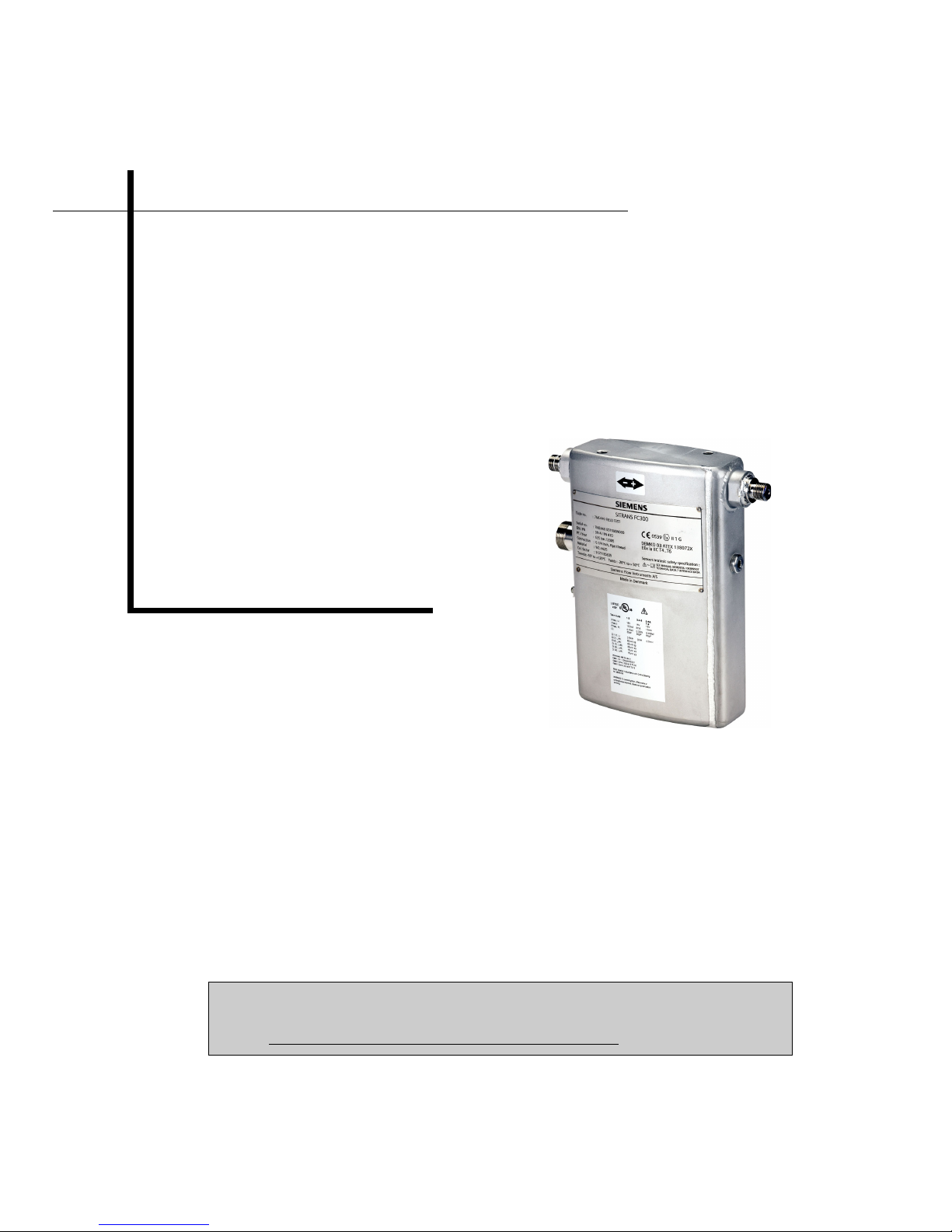
SITRANS F C MASSFLO
MASS flowmeters
Sensor type SITRANS FC300 DN 4
[]
Technical Documentation (handbooks, instructions, manuals etc.) for the complete product
range SITRANS F can be found on the internet/intranet via the following link:
English:
http://www4.ad.siemens.de/WW/view/en/10806951/133300

2
SFIDK.PS.028.S2.02
Introduction 1
General safety instructions 2
Description 3
Installation 4
Electrical connection 5
Commissioning 6
Troubleshooting 7
Specifications 8
Dimensional drawings 9
Appendix 10

3
SFIDK.PS.028.S2.02
Table of contents
1. Introduction ...................................................................................................................................... 4
1.1 Preface ............................................................................................................................................. 4
1.2 Further information ........................................................................................................................... 4
2. General safety instructions ............................................................................................................... 5
2.1 Safety notes ..................................................................................................................................... 5
2.2 Measures ......................................................................................................................................... 6
2.3 Transportation/storage ...................................................................................................................... 6
3. Description ....................................................................................................................................... 7
3.1 System configuration ........................................................................................................................ 7
3.2 Application ........................................................................................................................................ 8
3.3 Design .............................................................................................................................................. 8
3.4 Device identification.......................................................................................................................... 9
3.5 Mode of operation .......................................................................................................................... 10
4. Installation ...................................................................................................................................... 11
4.1 Safety information for installation .................................................................................................... 11
4.2 Location.......................................................................................................................................... 12
4.3 Orientation ...................................................................................................................................... 13
4.4 Mounting ........................................................................................................................................ 13
4.5 Vibrations ....................................................................................................................................... 14
4.6 Cross talk ....................................................................................................................................... 14
4.7 Process pipe connection ................................................................................................................ 15
4.8 Pressure guard............................................................................................................................... 15
5. Electrical connection ...................................................................................................................... 16
5.1 Connection safety information ........................................................................................................ 16
5.2 Connecting the multiple plug to the sensor ..................................................................................... 16
5.3 Connecting the sensor to the transmitter ........................................................................................ 17
5.4 Connecting of protective earth........................................................................................................ 18
6. Commissioning ............................................................................................................................... 19
6.1 Commissioning ............................................................................................................................... 19
7. Troubleshooting .............................................................................................................................. 20
7.1 Troubleshooting .............................................................................................................................. 20
8. Specifications ................................................................................................................................. 22
8.1 Specifications ................................................................................................................................. 22
8.2 Pressure and temperature (p/T) ratings.......................................................................................... 23
8.3 Pressure drop................................................................................................................................. 23
9. Dimensional drawings .................................................................................................................... 24
9.1 Standard version ............................................................................................................................ 24
9.2 High temperature version ............................................................................................................... 25
10. Appendix ........................................................................................................................................ 26
10.1 UL certificates ................................................................................................................................26
10.2 ATEX certificate, standard version −40... +115°C (−40...+239°F) ................................................... 27
10.3 ATEX certificate, high temperature version −40...+180°C (−40...+356°F) ....................................... 31

4
SFIDK.PS.028.S2.02
SITRANS FC MASSFLO coriolis mass flowmeters measure all types of liquids and gases. The
meter is a multiparameter device offering accurate measurement of mass flow, volume flow,
density, temperature, and fraction.
Technical Documentation (handbooks, instructions, manuals etc.) on the complete SITRANS F
product range can be found on the internet/intranet at the following link:
English: http://www4.ad.siemens.de/WW/view/en/10806951/133300
1.2 Further information
1.1 Preface
Introduction 1
This instruction contains all the information required to commission and operate the SITRANS
FC MASSFLO coriolis sensor, FC300.
The instruction is aimed at those installing the device, connecting it electronically, and
commissioning it, as well as service and maintenance engineers.

5
SFIDK.PS.028.S2.02
General safety instructions 2
2.1 Safety notes
For safety reasons it is important that the following points, especially the points marked with a
warning sign, are read and understood before the system is being installed:
• Installation, connection, commissioning and service must be carried out by qualified and
authorized personnel.
• It is very important that the users read and understand the instructions and directions
provided in this manual and that they follow the instructions and directions before taking the
equipment into use!
• People who are authorized and trained by the owner of the equipment may operate the
equipment.
• The installation must ensure that the measuring system is correctly connected and is in
accordance with the connection diagram.
• In applications with working pressures/media that can be dangerous to people, surroundings,
equipment, or others in case of pipe fracture, we recommend that special precautions such
as special placement, shielding, or installation of a security guard or a security valve should
be made when the sensor is being installed.
• Siemens Flow Instruments assist by estimating the chemical resistance of the sensor
parts that are in connection with the media, but it is at any time the customer’s responsibility,
which materials are chosen, and Siemens Flow Instruments takes no responsibility if the
sensor corrodes!
• Equipment used in hazardous areas must be Ex approved and marked for Europe and
UL for USA.
It is required that the special directions provided in the manual and in the Ex certificate
must be followed!
• Installation of the equipment must comply with national regulations.
Example: EN 60079-14 for Denmark.
• Repair and service can be done by approved Siemens Flow Instruments personnel only.
• The p/T ratings indicate the relation between the maximum allowable pressure PN and
the maximum allowable temperature.

6
SFIDK.PS.028.S2.02
2.2 Measures
Before commissioning
Warning
Before using this sensor please read the maximum operating pressure (PN) on the sensor label.
The operating pressure indicates the pressure to which measuring pipe and connections have
been dimensioned.
The enclosure/housing is not rated for pressure containment.
When working with operating pressures/media which in case of pipe fractures may cause injuries
to people, equipment, or anything else, we recommend special precautions when installing the
sensor, i.e. special placement, shielding, pressure guard or similar protective measures.
Please also refer to section 4, "Installation".
2.3 Transportation/storage
The sensor is a fragile piece of equipment. Therefore, during transportation it must be placed in
the transportation box originally delivered by Siemens Flow Instruments. If this is not possible,
the alternative sensor packaging must be able to withstand the hazards from transportation.

7
SFIDK.PS.028.S2.02
Description 3
3.1 System configuration
Integration
The sensor can be connected to all MASS 6000 transmitters for remote installation only.
All sensors are delivered with a SENSORPROM memory unit containing information about
calibration data, identity, and factory pre-programming of transmitter settings.
The SENSORPROM unit must be installed in the MASS 6000 transmitter.

8
SFIDK.PS.028.S2.02
3.2 Application
The industry today increasingly demands smaller mass flowmeters without loss of performance.
The SITRANS FC300 coriolis mass flowmeter is available in several configurations for direct
mass flow measurement of all kinds of liquids and gasses. The sensor is a multiparameter
device offering accurate measurement of mass flow rate, volume flow rate, density, temperature,
and fraction flow rate.
3.3 Design
The FC300 sensor consists of a single tube bent in a double pipe geometry, and welded directly
to the process connections at each end. The sensor is available in two material configurations
(AISI 316L or Hastelloy® C22 with ¼”-NPT or ¼”-ISO process connections).
The enclosure is stainless steel AISI 316L with an encapsulation grade of IP67/NEMA 4.
The enclosure is robustly designed, and with a size of 135 x 205 x 58 mm (5.31“ x 8.07“ x 2.28“)
the sensor is very compact, requiring little installation space.
The standard version sensor has a maximum liquid temperature of 115 °C (239 °F).
The high temperature version with raised electrical connector with raised electrical connector
has a maximum temperature of 180 °C (356 °F).
The sensor can be installed in either horizontal or vertical position. It can be mounted directly
on any plane surface or, if desired, with the enclosed quick-release clamp fitting. A compact
design and the multi-plug electrical connector keeps installation costs and time to a minimum.
9
SFIDK.PS.028.S2.02
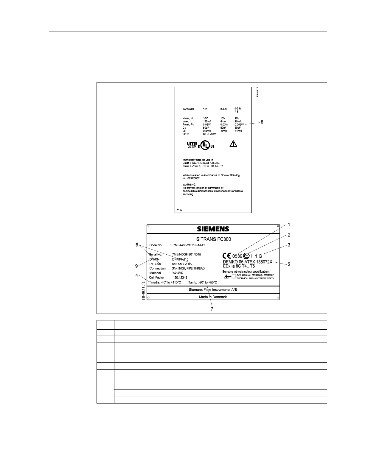
3.4 Device identification
No. Description
1. Notified body for QA supervision: UL International DEMKO A/S, Denmark
2. Explosion protected
3. ATEX Equipment Group and Protection Category
4. Medium temperature
5. EC Approval Numbers and Protection Type
6. Production year
7. Ambient temperature range
8. Interface data
9. DN = sensor size
PN = max. pressure [bar]
PT = test pressure, sensor pressure tested with 1.5 x PN
The nameplate located on the sensor housing front contains serial No. and other relevant
technical information.

10
SFIDK.PS.028.S2.02
3.5 Mode of operation
The flow measuring principle is based on coriolis law of movement.
The flowmeter consists of a sensor type FC300 and a transmitter MASS 6000.
The FC300 sensor is energized by an electromechanical driver circuit which oscillates the pipe
at its resonant frequency.
Two pick-ups, 1 and 2, are placed symmetrically on both sides of the driver. When liquid or gas
flows through the sensor, the coriolis force acts on the measuring pipe and causes a pipe
deflection which can be measured as a phase shift on pick-up 1 and 2. The phase shift is
proportional to the mass flow rate.
The amplitude of the driver is automatically regulated via a „Phase Locked Loop“ to ensure a
stable output from the two pick-ups in the region of 80 to 110 mV.
The temperature of the sensor is measured by a Pt1000, in a Wheatstone configuration (4-wire).
The flow proportional signal from the two pick-ups, the temperature measurement, and the driver
frequency are fed into the MASS 6000 transmitter used for calculations of mass flow, volume
flow, fraction flow, temperature, and density.
11
SFIDK.PS.028.S2.02
4.1 Safety information for installation
The SITRANS FC300 sensor can be installed for different areas of use.
Depending on area of application and system configuration, there may be differences in the
installation.
Installation 4
Warning
Protection against incorrect use of the measuring device.
Take particular care that the selected materials for the sensor pipes and the enclosure in contact
with the media are suitable for the process media used.
Ignoring this safety measure may cause injuries or life-threatening injuries to people and
damage the environment.
Warning
The device may only be used within the pressure and temperature range specified on the
nameplate.
Pressure overload might cause injuries and damage to people and the environment.
Warning
Category 1 equipment.
The FC300 may be installed in zone 0, zone 1 and zone 2.
 Loading...