

Siemens SITRANS FC430 Operating Instructions Manual
SITRANS F
Coriolis flowmeters
SITRANS FC430 with HART
Operating Instructions
05/2015Edition
Answers for industry.


SITRANS F
Coriolis Flowmeters
FC430 with HART
Operating Instructions
These Operating Instructions apply to Siemens
products SITRANS FC430 with order codes
comm
05/2015
A5E03361511
Introduction
1
Safety notes
2
Description
3
Installing/mounting
4
Connecting
5
Commissioning
6
Operating
7
Functions
8
Custody Transfer
9
Alarms and system
messages
10
Service and maintenance
11
Troubleshooting/FAQs
12
Technical data
13
Spare parts/Accessories
14
Dimensions and weight
15
HMI menu structure
A
HART commands
B
Default settings
C
Zero point adjustment
D
encing 7ME4613, 7ME4623 and 7ME4713
-AF

Siemens AG
Division Process Industries and Drives
Postfach 48 48
90026 NÜRNBERG
GERMANY
Order number: A5E03361511
Ⓟ
Copyright © Siemens AG 2011 - 2015.
All rights reserved
Legal information
Warning notice system
DANGER
indicates that death or severe personal injury will result if proper precautions are not taken.
WARNING
may
CAUTION
indicates that minor personal injury can result if proper precautions are not taken.
NOTICE
indicates that property damage can result if proper precautions are not taken.
Qualified Personnel
personnel qualified
Proper use of Siemens products
WARNING
Siemens products may only be used for the applications described in the catalog and in the relevant technical
maintenance are required to ensure that the products operate safely and without any problems. The permissible
ambient conditions must be complied with. The information in the relevant documentation must be observed.
Trademarks
Disclaimer of Liability
This manual contains notices you have to observe in order to ensure your personal safety, as well as to prevent
damage to property. The notices referring to your personal safety are highlighted in the manual by a safety alert
symbol, notices referring only to property damage have no safety alert symbol. These notices shown below are
graded according to the degree of danger.
indicates that death or severe personal injury
If more than one degree of danger is present, the warning notice representing the highest degree of danger will
be used. A notice warning of injury to persons with a safety alert symbol may also include a warning relating to
property damage.
result if proper precautions are not taken.
The product/system described in this documentation may be operated only by
task in accordance with the relevant documentation, in particular its warning notices and safety instructions.
Qualified personnel are those who, based on their training and experience, are capable of identifying risks and
avoiding potential hazards when working with these products/systems.
Note the following:
documentation. If products and components from other manufacturers are used, these must be recommended
or approved by Siemens. Proper transport, storage, installation, assembly, commissioning, operation and
All names identified by ® are registered trademarks of Siemens AG. The remaining trademarks in this publication
may be trademarks whose use by third parties for their own purposes could violate the rights of the owner.
We have reviewed the contents of this publication to ensure consistency with the hardware and software
described. Since variance cannot be precluded entirely, we cannot guarantee full consistency. However, the
information in this publication is reviewed regularly and any necessary corrections are included in subsequent
editions.
for the specific
05/2015 Subject to change

Table of contents
1 Introduction ............................................................................................................................................. 9
2 Safety notes .......................................................................................................................................... 21
3 Description ............................................................................................................................................ 29
4 Installing/mounting ................................................................................................................................ 41
5 Connecting ........................................................................................................................................... 55
1.1 History ....................................................................................................................................... 9
1.2 Compatibility ........................................................................................................................... 10
1.3 Items supplied ......................................................................................................................... 11
1.4 Checking the consignment ..................................................................................................... 12
1.5 Device identification ................................................................................................................ 12
1.6 Further Information ................................................................................................................. 19
2.1 Laws and directives ................................................................................................................ 21
2.2 Installation in hazardous locations .......................................................................................... 23
2.3 Certificates .............................................................................................................................. 28
3.1 Applications ............................................................................................................................. 29
3.2 System configuration .............................................................................................................. 30
3.3 Design ..................................................................................................................................... 31
3.4 Features .................................................................................................................................. 35
3.5 HART Communication Interface ............................................................................................. 37
3.6 Theory of operation ................................................................................................................. 40
4.1 Introduction ............................................................................................................................. 41
4.2 Strong vibrations ..................................................................................................................... 41
4.3 Transmitter installation ............................................................................................................ 41
4.3.1 Wall mounting ......................................................................................................................... 42
4.3.2 Pipe mounting ......................................................................................................................... 42
4.3.3 Mounting the transmitter ......................................................................................................... 43
4.3.4 Turning the transmitter ............................................................................................................ 43
4.3.5 Turning the local display ......................................................................................................... 45
4.4 Sensor installation ................................................................................................................... 46
4.4.1 Installation safety precautions ................................................................................................ 46
4.4.2 Determining a location ............................................................................................................ 47
4.4.3 Orientation of the sensor ........................................................................................................ 48
4.4.4 Mounting the sensor ............................................................................................................... 51
4.4.5 Hydrostatic testing .................................................................................................................. 53
4.4.6 Mounting a pressure guard ..................................................................................................... 53
FC430 with HART
Operating Instructions, 05/2015, A5E03361511-AF
3

Table of contents
6 Commissioning ..................................................................................................................................... 73
7 Operating ............................................................................................................................................. 109
5.1 General safety requirements .................................................................................................. 55
5.2 Wiring in hazardous locations ................................................................................................ 56
5.3 Cable requirements ................................................................................................................ 56
5.4 Safety notes for connecting ................................................................................................... 57
5.5 Step 1: Connecting the DSL and the transmitter ................................................................... 57
5.6 Lack of equipotential bonding ................................................................................................ 61
5.7 Step 2: Preparing for the transmitter connections ................................................................. 61
5.8 Step 3: Connecting the power supply .................................................................................... 66
5.9 Step 4a: Connecting the current output HART (channel 1) ................................................... 68
5.10 Step 4b: Connecting the inputs and outputs (channels 2 to 4) .............................................. 69
5.11 Step 5: Finishing the transmitter connection .......................................................................... 72
6.1 General requirements ............................................................................................................ 73
6.2 Warnings ................................................................................................................................ 73
6.3 Commissioning via HMI ......................................................................................................... 74
6.3.1 Wizard introduction ................................................................................................................ 74
6.3.2 Quick Commissioning wizard (menu item 1.1) ...................................................................... 75
6.3.3 Zero point adjustment ............................................................................................................ 76
6.3.4 Zero Point Adjustment wizard (menu item 1.2) ...................................................................... 77
6.3.5 Wizards .................................................................................................................................. 78
6.3.5.1 Process Values wizard (menu item 1.3) ................................................................................ 80
6.3.5.2 Inputs/Outputs wizard (menu item 1.4) .................................................................................. 81
6.3.5.3 Gas Application wizard (menu item 1.5) ................................................................................ 85
6.3.5.4 Pulsating Flow wizard (menu item 1.6) .................................................................................. 86
6.3.5.5 Dosing Application wizard (menu item 1.7) ........................................................................... 87
6.4 Commissioning with PDM ...................................................................................................... 88
6.4.1 Operating via SIMATIC PDM ................................................................................................. 88
6.4.2 Functions in SIMATIC PDM ................................................................................................... 88
6.4.3 Initial setup ............................................................................................................................. 89
6.4.4 Adding device to communication network .............................................................................
6.
4.5 Configuring a new device ....................................................................................................... 92
91
6.4.6 Wizard - Quick Start via PDM ................................................................................................ 92
6.4.7 Wizard - Zero Point adjustment ........................................................................................... 100
6.4.8 Changing parameter settings using SIMATIC PDM ............................................................ 102
6.4.9 Parameters accessed via drop-down menus ....................................................................... 103
6.4.10 Zero point adjustment .......................................................................................................... 105
6.4.11 Process variables ................................................................................................................. 107
7.1 Local display (HMI) .............................................................................................................. 109
7.1.1 Display view structure .......................................................................................................... 110
7.1.2 Access control ...................................................................................................................... 115
7.1.3 Operation view ..................................................................................................................... 116
7.1.4 Navigation view .................................................................................................................... 125
7.1.5 Parameter view .................................................................................................................... 127
FC430 with HART
4 Operating Instructions, 05/2015, A5E03361511-AF

Table of contents
8 Functions ............................................................................................................................................ 131
9 Custody Transfer ................................................................................................................................ 161
10 Alarms and system messages ............................................................................................................. 171
11 Service and maintenance .................................................................................................................... 181
8.1 Process values ...................................................................................................................... 131
8.2 Zero point adjustment ........................................................................................................... 134
8.3 Low flow cut-off ..................................................................................................................... 135
8.4 Empty tube monitoring .......................................................................................................... 135
8.5 Process noise damping......................................................................................................... 136
8.6 Inputs and outputs ................................................................................................................ 138
8.6.1 Current output ....................................................................................................................... 139
8.6.2 Pulse output .......................................................................................................................... 144
8.6.3 Frequency output .................................................................................................................. 145
8.6.4 Redundancy mode ................................................................................................................ 146
8.6.5 Status output ......................................................................................................................... 147
8.6.6 Input ...................................................................................................................................... 147
8.7 Totalizers .............................................................................................................................. 148
8.8 Dosing ................................................................................................................................... 149
8.8.1 Dosing control configuration ................................................................................................. 150
8.8.2 Valve control configuration ................................................................................................... 151
8.8.3 Dosing operation ................................................................................................................... 156
8.8.4 F
ault handling ....................................................................................................................... 157
8.9 Audit trail ............................................................................................................................... 157
8.10 Alarm acknowledgement ...................................................................................................... 157
8.11 Custom unit ........................................................................................................................... 158
8.12 SensorFlash .......................................................................................................................... 158
8.13 Simulation ............................................................................................................................. 158
8.14 Maintenance ......................................................................................................................... 160
9.1 Operating conditions ............................................................................................................. 161
9.2 Verification ............................................................................................................................ 161
9.3 Setting up custody transfer mode ......................................................................................... 163
9.4 Parameter protection in custody transfer mode .................................................................... 166
9.5 Disabling custody transfer mode .......................................................................................... 170
10.1 Overview of messages and symbols .................................................................................... 171
10.2 Alarm messages ................................................................................................................... 172
11.1 Maintenance ......................................................................................................................... 181
11.2 Service information ............................................................................................................... 181
11.3 Recalibration ......................................................................................................................... 182
FC430 with HART
Operating Instructions, 05/2015, A5E03361511-AF
5

Table of contents
12 Troubleshooting/FAQs ......................................................................................................................... 187
13 Technical data ..................................................................................................................................... 193
14 Spare parts/Accessories ...................................................................................................................... 217
15 Dimensions and weight ........................................................................................................................ 223
11.4 Technical support ................................................................................................................. 183
11.5 Transportation and storage .................................................................................................. 184
11.6 Cleaning ............................................................................................................................... 184
11.7 Repair ................................................................................................................................... 184
11.8 Return and disposal ............................................................................................................. 185
12.1 Diagnosing with PDM ........................................................................................................... 187
12.2 Troubleshooting sensor-related problems ........................................................................... 187
12.3 How do I copy application setup from one device to another? ............................................ 192
12.4 How do I update the firmware? ............................................................................................ 192
13.1 Function and system design ................................................................................................ 193
13.2 SensorFlash ......................................................................................................................... 193
13.3 Process variables ................................................................................................................. 194
13.4 Bus communication .............................................................................................................. 195
13.5 Performance ......................................................................................................................... 195
13.6 Rated operating conditions .................................................................................................. 196
13.7 Pressure drop curves ........................................................................................................... 197
13.8 Pressure - temperature ratings ............................................................................................ 198
13.9 Design .................................................................................................................................. 201
13.10 Inputs and outputs ............................................................................................................... 203
13.11 Local display (HMI) .............................................................................................................. 205
13.12 Power supply ........................................................................................................................ 205
13.13 Cables and cable entries ..................................................................................................... 205
13.14 Installation torques ............................................................................................................... 207
13.15 Certificates and approvals HART......................................................................................... 209
13.16 PED ...................................................................................................................................... 211
14.1 Ordering ............................................................................................................................... 217
14.2 Ex approved products .......................................................................................................... 217
14.3 Replaceable components .................................................................................................... 218
15.1 Sensor dimensions .............................................................................................................. 223
15.2 Lengths matrix...................................................................................................................... 224
15.3 Transmitter dimensions ........................................................................................................ 229
FC430 with HART
6 Operating Instructions, 05/2015, A5E03361511-AF

Table of contents
A HMI menu structure............................................................................................................................. 231
B HART commands ................................................................................................................................ 257
C Default settings ................................................................................................................................... 259
15.4 Mounting bracket .................................................................................................................. 230
A.1 Main menu ............................................................................................................................ 231
A.2 Menu item 2.1: Basic Settings .............................................................................................. 232
A.3 Menu item 2.2: Process Values ............................................................................................ 233
A.4 Menu item 2.3: Totalizer ....................................................................................................... 235
A.5 Menu item 2.4: Inputs/Outputs .............................................................................................. 236
A.6 Menu item 2.5: Dosing .......................................................................................................... 241
A.7 Menu item 2.6: Zero Point Adjustment ................................................................................. 245
A.8 Menu item 2.7: Safe Operation ............................................................................................. 245
A.9 Menu item 2.8: Display ......................................................................................................... 246
A.10 Menu item 3.1: Identification ................................................................................................. 248
A.11 Menu item 3.2: Alarms .......................................................................................................... 249
A.12 Menu item 3.3: Maintenance ................................................................................................ 250
A.13 Menu item 3.4: Diagnostics .................................................................................................. 251
A.14 Menu item 3.5: Characteristics ............................................................................................. 251
A.15 Menu item 3.6: SensorFlash ................................................................................................. 252
A.16 Menu item 3.7: Simulate ....................................................................................................... 252
A.17 Menu item 3.8: Audit Trail ..................................................................................................... 254
A.18 Menu item 3.9: Aerated Flow ................................................................................................
19 Menu item 3.10: Self Test ..................................................................................................... 255
A.
254
A.20 Menu item 4.6: Mapping of Variables ................................................................................... 255
A.21 Menu item 4.7: HART units ................................................................................................... 255
A.22 Menu item 5.1: Access Management ................................................................................... 256
B.1 Universal commands ............................................................................................................ 257
B.2 Common practice commands ............................................................................................... 257
C.1 Basic Settings ....................................................................................................................... 259
C.2 Process Values ..................................................................................................................... 260
C.3 Totalizer ................................................................................................................................ 270
C.4 Inputs/Outputs ....................................................................................................................... 276
C.5 Dosing ................................................................................................................................... 307
C.6 Zero Point Adjustment .......................................................................................................... 329
C.7 Safe Operation ...................................................................................................................... 330
FC430 with HART
Operating Instructions, 05/2015, A5E03361511-AF
7

Table of contents
D Zero point adjustment .......................................................................................................................... 379
Glossary .............................................................................................................................................. 383
Index ................................................................................................................................................... 385
C.8 Display ................................................................................................................................. 331
C.9 Maintenance & Diagnostics ................................................................................................. 356
C.10 Communication .................................................................................................................... 367
C.11 Security ................................................................................................................................ 372
C.12 Language ............................................................................................................................. 373
C.13 Sensor dimension dependent default settings ..................................................................... 373
FC430 with HART
8 Operating Instructions, 05/2015, A5E03361511-AF

1
1.1
History
Edition
Remarks
EDD version
FW revision
These instructions contain all information required to commission and use the device. Read
the instructions carefully prior to installation and commissioning. In order to use the device
correctly, first review its principle of operation.
The instructions are aimed at persons mechanically installing the device, connecting it
electronically, configuring the parameters and commissioning it, as well as service and
maintenance engineers.
The contents of this manual shall not become part of or modify any prior or existing
agreement, commitment or legal relationship. The sales contract contains all obligations on
the part of Siemens as well as the complete and solely applicable warranty conditions. Any
statements regarding device versions described in the manual do not create new warranties
or modify the existing warranty.
The content reflects the technical status at the time of publishing. Siemens reserves the right
to make technical changes in the course of further development.
03/2012
06/2012
12/2013
The following table shows major changes in the documentation compared to the previous
edition.
• First edition • SIMATIC PDM driver 1.00.00
• CT chapter included • SIMATIC PDM driver 1.00.00 • Standard version:
• Various LUI functions, for
example wizards
• Various transmitter func-
tionalities
• SIMATIC PDM driver 2.00.00-**
• AMS Device Manager 2.00.00-**
• SITRANS DTM 2.00.00-**
• 375 Field Communicator 2.00.00-**
– Compact: 3.00.00-10
– Remote: 2.00.00-30
• CT version:
– Compact: 3.00.00-11
– Remote: 2.00.00-31
• Compact version: 3.02.0*-**
• Remote version: 2.02.0*-**
FC430 with HART
Operating Instructions, 05/2015, A5E03361511-AF
9

Introduction
Edition
Remarks
EDD version
FW revision
1.2
Compatibility
FW/HW revisions and EDD versions compatibility
FW revision
HW revision
HART EDDs
(PDM/AMS/DTM/HCF)
2.00.0x-xx
01
V 1.00.00-xx, Revision 1
2.02.02-xx
02
V 4.00.00-xx, Revision 3
FW revision
HW revision
HART EDDs
(PDM/AMS/DTM/HCF)
3.00.0x-xx
01
V 1.00.00-xx, Revision 1
3.02.00-xx
02
V 2.00.00-xx, Revision 2
02
V 4.00.00-xx, Revision 3
1.2 Compatibility
05/2014
05/2015
• Description of new param-
eters for spare part replacement
• Aerated Flow parameters
added
• SIMATIC PDM driver 3.00.00-**
• AMS Device Manager 3.00.00-**
• SITRANS DTM 3.00.00-**
• 375 Field Communicator 3.00.00-**
• SIMATIC PDM driver HART EDD:
4.00.00-00 **
• SIMATIC PDM driver MODBUS:
4.00.00-00 **
• AMS Device driver HART: 4.00.00-
02 **
• SITRANS DTM HART: 4.00.00-00 **
• 375 Field Communicator HART:
4.00.00-02 **
• Compact version: 3.02.01-**
• Remote version: 2.02.01-**
• Compact version: 3.02.02-01
**
• Remote version: 2.02.02-01
**
Table 1- 1 Remote version
2.02.00-xx 02 V 2.00.00-xx, Revision 2
Table 1- 2 Compact version
3.02.02-xx
FC430 with HART
10 Operating Instructions, 05/2015, A5E03361511-AF
Introduction
1.3
Items supplied
Compact system
•
•
•
•
Remote system
Remote with M12 plug connection
•
•
•
•
•
•
•
Remote with sensor terminal housing
•
•
•
•
•
•
•
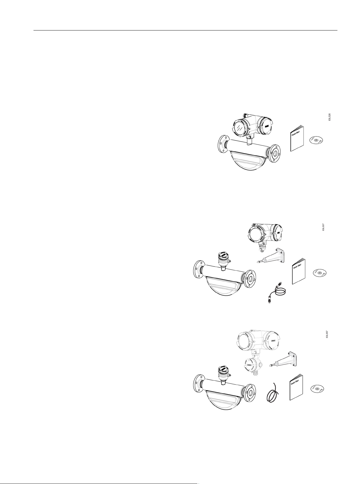
1.3 Items supplied
The device can be delivered as either a compact or a remote system.
SITRANS FC430 sensor and compact
mounted transmitter
Packet of cable glands
Quick Start guide
CD containing software, certificates and
device manuals
SITRANS FCS400 sensor
SITRANS FCT030 transmitter with
M12 socket assembled
Mounting bracket and cushion pad
Sensor cable with M12 connector
Packet of cable glands
Quick Start guide
CD containing software, certificates
and device manuals
SITRANS FCS400 sensor
SITRANS FCT030 transmitter with
terminal housing assembled
Mounting bracket and cushion pad
Sensor cable
Packet of cable glands
Quick Start guide
CD containing software, certificates
FC430 with HART
Operating Instructions, 05/2015, A5E03361511-AF
and device manuals
11

Introduction
Note
Supplementary information
Supplementary prod
®
SD card in the transmitter socket.
Note
Scope of delivery may vary, depending on version and add
delivery and the information on the nameplate corres
note.
1.4
Checking the consignment
WARNING
Using a damaged or incomplete device
1.5
Device identification
Note
Identification
Identify your device by comparing your ordering data with the inform
and specification nameplates.
1.4 Checking the consignment
uct and production specific certificates are included on the SensorFlash
-ons. Make sure the scope of
pond to your order and the delivery
1. Check the packaging and the delivered items for visible damage.
2. Report any claims for damages immediately to the shipping company.
3. Retain damaged parts for clarification.
4. Check the scope of delivery by comparing your order to the shipping documents for
correctness and completeness.
Danger of explosion in hazardous areas.
• Do not use damaged or incomplete devices.
Each part of the FC430 Coriolis flowmeter has three nameplate types showing the following
information:
● product identification
● product specifications
● certificates and approvals
FC430 with HART
12 Operating Instructions, 05/2015, A5E03361511-AF
ation on the product
Introduction
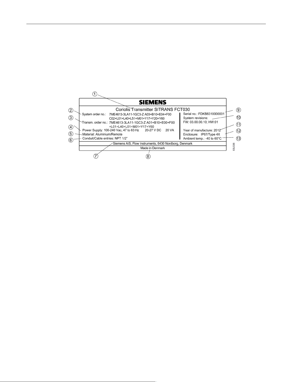
FCT030 transmitter identification nameplate
①
Product name
Transmitter product name
②
System order no.
Device-specific system order number (transmitter and sensor)
③
Transm. order no.
Transmitter replacement order number
④
Power Supply
Power supply
⑤
Material
Transmitter housing material and style (compact/remote)
⑥
Conduit / cable entries
Type of conduit / cable entries
⑦
Manufacturer
Manufacturer name and location
⑧
Country
Manufacturing country
⑨
Serial no.
Transmitter serial number
⑩
System revisions
System revision numbers; firmware (FW) and hardware (HW)
⑪
serial number (see sensor identification nameplate above)
⑫
Enclosure IP
Degree of protection
⑬
Ambient temp.
Ambient temperature
1.5 Device identification
With compact versions, the transmitter and sensor product identifications are both given as
'Coriolis flowmeter SITRANS FC430'.
With remote versions, the transmitter is identified as 'Coriolis transmitter SITRANS FCT030'
and the sensor as 'Coriolis sensor SITRANS FCS400'.
Year of Manufacture Manufacturing year
Figure 1-1 FCT030 identification nameplate example
FC430 with HART
Operating Instructions, 05/2015, A5E03361511-AF
More detailed manufacturing date information is given in the
13
Introduction
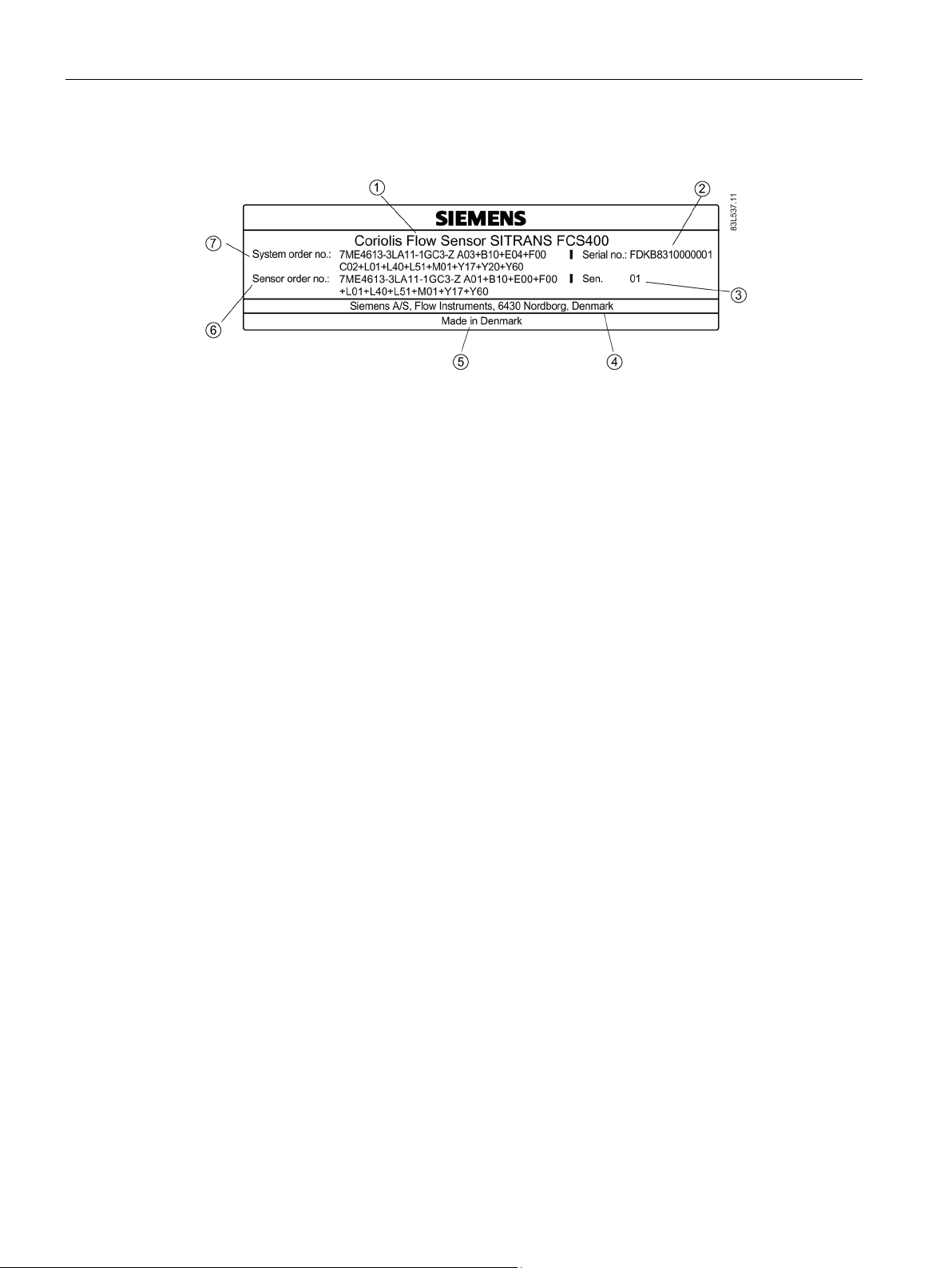
FCS400 sensor identification nameplate
①
Product name
Sensor product name
②
Serial no.
Sensor serial number
③
Sen.
Mechanical sensor version number
④
Manufacturer
Manufacturer name and location
⑤
Country
Manufacturing country
⑥
Sensor order no.
Sensor replacement order number
⑦
System order no.
Flowmeter system order number (transmitter and sensor)
Flowmeter serial number construction
Calendar year (Y)
Code
1950, 1970, 1990, 2010
A
1951, 1971, 1991, 2011
B
1952, 1972, 1992, 2012
C
1953, 1973, 1993, 2013
D
1954, 1974, 1994, 2014
E
1955, 1975, 1995, 2015
F
1956, 1976, 1996, 2016
H (G)
1957, 1977, 1997, 2017
J
1958, 1978, 1998, 2018
K
1959, 1979, 1999, 2019
L
1960, 1980, 2000, 2020
M
1.5 Device identification
Figure 1-2 FCS400 identification nameplate example
The flowmeter serial number is constructed as follows:
PPPYMDDxxxxxx
where
PPP = Production factory (Siemens Flow Instruments: FDK)
Y = Production year (for encryption, see below)
M = Production month (for encryption, see below)
DD = Production date (for encryption, see below)
xxxxxx = Sequential number
Encryption:
FC430 with HART
14 Operating Instructions, 05/2015, A5E03361511-AF

Introduction
1961, 1981, 2001, 2021
N
1962, 1982, 2002, 2022
P
1963, 1983, 2003, 2023
R
1964, 1984, 2004, 2024
S
1965, 1985, 2005, 2025
T
1966, 1986, 2006, 2026
U
1967, 1987, 2007, 2027
V
1968, 1988, 2008, 2028
W
1969, 1989, 2009, 2029
X
Month (M)
Code
January
1
February
2
March
3
April
4
May
5
June
6
July
7
August
8
September
9
October
O
November
N
December
D
Date (DD)
Code
Day 1 to 31
01 to 31 (corresponding to the actual date)
1.5 Device identification
FC430 with HART
Operating Instructions, 05/2015, A5E03361511-AF
15
Introduction
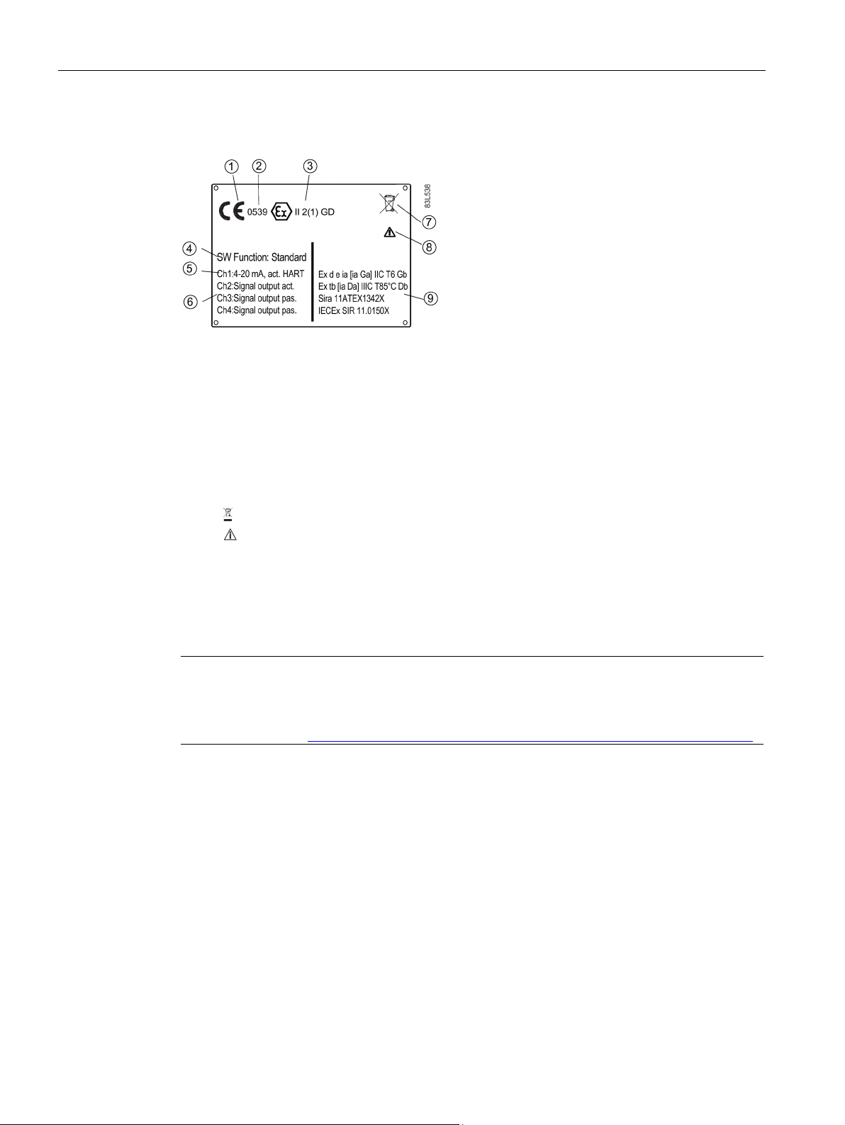
FCT030 transmitter specification nameplate
①
CE
CE mark
②
0539
ATEX Notified Body ID (UL-DEMKO)
③
Ex
Ex mark Installation in hazardous locations (Page 23)
④
SW Function
Software function ("Standard" or "CT standard")
⑤
HART, active or passive)
⑥
Ch4
⑦
WEEE symbol, see Return and disposal (Page 185)
⑧
Consult the operating instructions
⑨
Ex approval specifications for the transmitter (ATEX example; for
(Page 209))
Note
Approval identifications
Approval certificates and notified body identifications are available for download at
www.siemens.com (
1.5 Device identification
Ch1 Communication interface on channel 1 (always 4-20 mA with
Ch2
Ch3
Ex approvals
Figure 1-3 FCT030 specification nameplate example
Input/output setup of channels 2 to 4, if ordered
details on all approvals refer to Certificates and approvals HART
http://support.automation.siemens.com/WW/view/en/60666565/134200).
FC430 with HART
16 Operating Instructions, 05/2015, A5E03361511-AF
Introduction
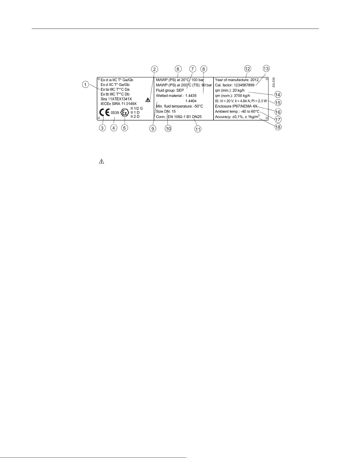
FCS400 sensor specification nameplate
①
(Page 209))
②
Consult the operating instructions
③
CE
CE mark
④
0539
Notified Body ID (ATEX example)
⑤
Ex
Ex mark, Installation in hazardous locations (Page 23)
⑥
°C (392 °F) (max. temperature (TS))
⑦
Fluid group
Fluid group statement required by PED
⑧
Wetted material
Measuring tube/process connection materials
⑨
Min. fluid temperature
Minimum fluid temperature
⑩
Size DN
Nominal size
⑪
Conn.
Process connection type and size
⑫
serial number found on the identification nameplate
⑬
Cal. Factor
Calibration factor
⑭
Qm (nom)
⑮
internal)
⑯
Enclosure IP
Degree of protection
⑰
Ambient Temp.
Ambient temperature range
⑱
Accuracy
Massflow, density calibration accuracy
1.5 Device identification
Ex approvals Ex approval specifications for the sensor (ATEX example; for
details on all approvals refer to Certificates and approvals HART
MAWP Maximum allowable working pressures at 20 °C (68 °F) and 200
Year of Manufacture Manufacturing year
More detailed manufacturing date information is given in the
Qm (min)
Power Supply Power supply (not given on the compact variant because it is
Figure 1-4 FCS400 specification nameplate example
Minimum and nominal massflows with water at 20 °C (68 °F)
FC430 with HART
Operating Instructions, 05/2015, A5E03361511-AF
17
Introduction
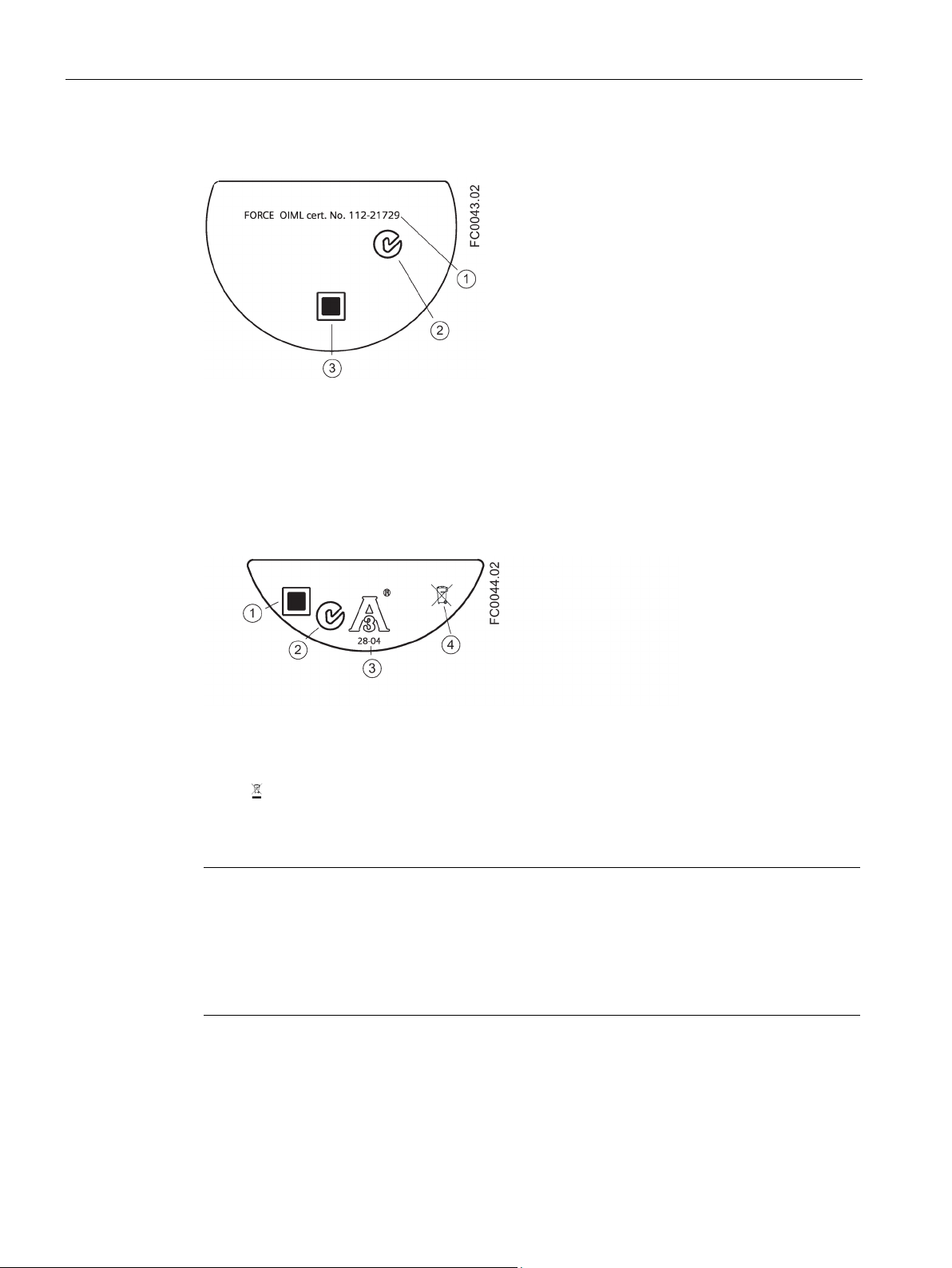
FCT030 transmitter approval nameplate
①
FORCE OIML
Custody Transfer evaluation certificate number
②
C✓
C-tick logo
③
QR code
Product-specific QR code
FCS400 sensor approval nameplate
①
QR code
Product-specific QR code
②
C✓
C-tick logo
③
3A
3A logo
④
WEEE symbol, see Return and disposal (Page 185)
Note
Logos and warnings
Logos and warnings are only shown on the product where applicable. The combination
shown in the example above is relevant for a hygienic sensor installed in hazardous location
in Canada.
The Australian C
1.5 Device identification
Figure 1-5 FCT030 approval nameplate example
Figure 1-6 FCS400 approval nameplate example
-tick mark is mandatory on all products.
FC430 with HART
18 Operating Instructions, 05/2015, A5E03361511-AF
Introduction
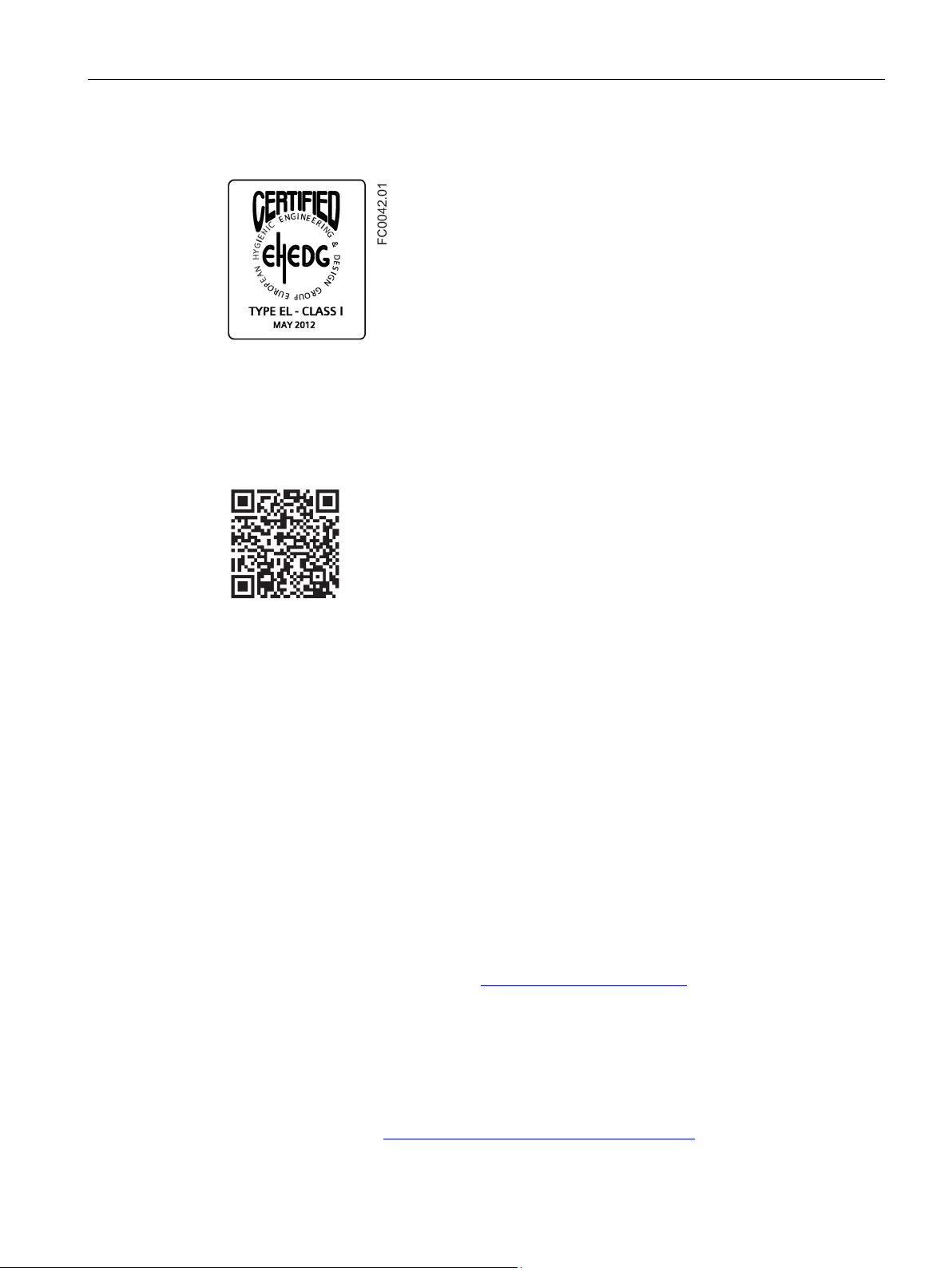
FCS400 EHEDG nameplate
Other label
1.6
Further Information
Product information on the Internet
Worldwide contact person
1.6 Further Information
Figure 1-7 EHEDG nameplate
This nameplate appears on all Hygienic sensors 7ME462.
Figure 1-8 How to install
The QR code provides direct internet connection to
● The product support portal, which includes access to the "How to Install" YouTube video.
(This example provides that function.)
● Product and production-specific documentation maintained in the production database.
The Operating Instructions are available on the documentation disk shipped with the device,
and on the Internet on the Siemens homepage, where further information on the range of
SITRANS F flowmeters may also be found:
Product information on the internet (http://www.siemens.com/flow
)
If you need more information or have particular problems not covered sufficiently by these
Operating Instructions, get in touch with your contact person. You can find contact
information for your local contact person on the Internet:
Local contact person (http://www.automation.siemens.com/partner
FC430 with HART
Operating Instructions, 05/2015, A5E03361511-AF
)
19

Introduction
1.6 Further Information
FC430 with HART
20 Operating Instructions, 05/2015, A5E03361511-AF
2
Symbol
Explanation
Note
Functional safety applications (SIL)
In case the device is used in a functional safety application, refer to the functional safety
manual.
2.1
Laws and directives
This device left the factory in good working condition. In order to maintain this status and to
ensure safe operation of the device, observe these instructions and all the specifications
relevant to safety.
Observe the information and symbols on the device. Do not remove any information or
symbols from the device. Always keep the information and symbols in a completely legible
state.
Consult operating instructions
Observe the test certification, provisions and laws applicable in your country during
connection, assembly and operation. These include, for example:
● National Electrical Code (NEC - NFPA 70) (USA)
● Canadian Electrical Code (CEC) (Canada)
Further provisions for hazardous area applications are for example:
● IEC 60079-14 (international)
● EN 60079-14 (EC)
FC430 with HART
Operating Instructions, 05/2015, A5E03361511-AF
21

Safety notes
Conformity with European directives
Electromagnetic compatibi
ity EMC
2004/108/EC
Directive of the European Parliament and of the Council on the
approximation of the laws of the Member States relating to electromagnetic compatibility and repealing Directive 89/336/EEC.
Low voltage directive LVD
2006/95/EC
Directive of the European Parliament and of the Council on the
harmonisation of the laws of Member States relating to electr
cal equipment designed for use within certain voltage limits.
Atmosphère explosible
ATEX
94/9/EC
Directive of the European Parliament and the Council on the
approximation of the laws of the Member States concerning
equipment and protective systems intended for use in potentia
ly explosive atmospheres.
Pressure equipment d
rective PED
97/23/EC
Directive of the European Parliament and of the Council on the
approximation of the laws of the Member States concerning
pressure equipment.
WARNING
Improper device modifications
Note
CE declaration
The CE declaration certificate is required to be included with each flowmeter. The certificate
is therefore available on the SensorFlash SD card delivered with the device.
2.1 Laws and directives
The CE marking on the device symbolizes the conformity with the following European
directives:
l-
i-
The applicable directives can be found in the EC conformity declaration of the specific
device. Further country or region-specific code conformity information is available on
request.
i-
l-
Danger to personnel, system and environment can result from modifications to the device,
particularly in hazardous areas.
• Only carry out modifications that are described in the instructions for the device. Failure
to observe this requirement cancels the manufacturer's warranty and the product
approvals.
FC430 with HART
22 Operating Instructions, 05/2015, A5E03361511-AF

Safety notes
2.2
Installation in hazardous locations
WARNING
Equipment used in hazardous locations
Hazardous area approvals
ATEX:
2.2 Installation in hazardous locations
Equipment used in hazardous locations must be Ex-approved for the region of installation
and marked accordingly. It is required that the special conditions for safe use provided in
the manual and in the Ex certificate are followed!
The device is approved for use in hazardous area and has the approvals listed below.
Special conditions for safe installation and operation specified by each approval authority are
included in the relevant certificate.
FCT030 transmitter (can be installed in Zone 1 for gas and Zone 21 for dust):
Certificate: SIRA 11ATEX1342X
II 2(1) GD
Ex d e [ia Ga] IIC T6 Gb Ta = -40°C to +60°C
Ex tb [ia Da] IIIC T85°C Db
FCS400 sensor + DSL (can be installed in Zone 1 for gas and Zone 20/21 for dust):
Certificate: SIRA 11ATEX1341X
II 1/2 G
1D
2D
For gas:
Ex d ia IIC T* Ga/Gb
Ex d IIC T* Ga/Gb
(Ga/Gb: Zone 20 in pipe and Zone 21 in environment)
For dust:
Ex ta IIIC T* °C Da
Ex tb IIIC T* °C Db
(Zone 20 ("ta") process and ambient temperature limited in comparison with Zone 21 ("tb")
Ta = -40°C to +60°C
* Temperature class (dependent on the process temperature and the ambient temperature")
FC430 compact system (can be installed in Zone 1 for gas and Zone 21 for dust):
Certificate: SIRA 12ATEX1102X
II 1/2 (1) G
II 2 D
FC430 with HART
Operating Instructions, 05/2015, A5E03361511-AF
23

Safety notes
IECEx:
FM:
Note
Control drawing
*
2.2 Installation in hazardous locations
Ex d e ia [ia GA] IIC T* Ga/Gb Ta = -40°C to ** °C
Ex tb [ia Da] IIIC T**°C Db
(Ga/Gb: Zone 20 in pipe and Zone 21 in environment)
* Temperature class (dependent on the "Maximum Process Temperature")
** Upper ambient temperature (dependent on the "Maximum Process Temperature")
FCT030 transmitter (can be installed in Zone 1 for gas and Zone 21 for dust):
Certificate: IECEx SIR 11.0150X
Ex d e ia [ia Ga] IIC T6 Gb Ta = -40°C to +60°C.
Ex tb [ia Da] IIIC T85°C Db
FCS400 sensor + DSL (can be installed in Zone 1 for gas and Zone 20/21 for dust):
Certificate: IECEx SIR 11.0149X
For gas:
Ex d ia IIC T* Ga/Gb
Ex d IIC T* Ga/Gb
(Ga/Gb: Zone 20 in pipe and Zone 21 in environment)
For dust:
Ex ta IIIC T* °C Da
Ex tb IIIC T* °C Db
(Zone 20 ("ta") process and ambient temperature limited in comparison with Zone 21 ("tb")
Ta = -40°C to +60°C
* Temperature class (dependent on the process temperature and the ambient temperature")
FC430 compact system (can be installed in Zone 1 for gas and Zone 21 for dust):
Certificate: IECEx SIR 12.0040X
Ex d e ia [ia Da] IIC Ga/Gb Ta= -40 to ** °C
Ex tb [ia Da] IIIC T ** °C Db
* Temperature class (dependent on the "Maximum Process Temperature")
** Upper ambient temperature (dependent on the "Maximum Process Temperature")
Transmitter (FCT030), Sensor with DSL (FCS400) and Compact (FC430):
Class I Division 1 Groups A,B,C,D T* (XP, IS)
Class II Division 1 Groups E,F,G
Class III Division 1 Group H (granulates)
Class I Zone 1 and Zone 21
Class 1 Zone 1 and Zone 20 (FCS400 remote)
FC430 with HART
24 Operating Instructions, 05/2015, A5E03361511-AF
See Control drawing: A5E31205486A

Safety notes
Installation variations
Note
Requirements for safe installation
•
•
•
•
Maximum temperature specifications for Ex use
FCS400 remote sensor with DSL
Ta (°C)
Maximum Process Temperature per Temperature Class (°C)
T6
T5
T4
T3
60
70
70
70
70
55
85
100
100
100
50
85
100
130
130
45
85
100
135
160
40
85
100
135
190
35
85
100
135
200
30
85
100
135
200
Ta (°C)
Maximum Process Temperature per Temperature
Class (°C)
60
70
55
100
50
130
45
160
40
190
30
200
2.2 Installation in hazardous locations
Remote sensor FCS400 can be installed in Zone 1, Div. 1 as Intrinsically Safe or
Flameproof.
Standard remote installation with FCT030 because the connection is certified Intrinsically
Safe. however flameproof seals and conduit (for IS cable) can be used.
Requirement for IS circuit is that the maximum input voltage Vi to DSL is 20 VDC, Ii is
maximum 484 mA, Pi < 2.3 W
In Ex d installation Um is 24 VDC
Temperature classification with and without dust is related to the process temperature and
ambient temperature as listed below.
The maximum allowable process fluid temperatures with respect to temperature class for the
device when used with potentially explosive gases in a maximum ambient temperature of
+60°C are:
If the equipment is placed in a "tb" environment (Zone 21), the maximum process
temperatures shall be as follows:
FC430 with HART
Operating Instructions, 05/2015, A5E03361511-AF
35 200
25

Safety notes
Ta (°C)
Maximum Process Temperature per Temperature
Class (°C)
60
-40
50
20
45
50
40
80
35
110
30
140
FC430 compact flowmeter
Ta (°C)
Maximum Process Temperature per Temperature Class (°C)
T6
T5
T4
T3
60
80
80
80
80
55
85
100
110
110
50
85
100
135
140
45
85
100
135
170
40
85
100
135
200
35
85
100
135
200
30
85
100
135
200
FCT030 remote transmitter
2.2 Installation in hazardous locations
Additionally, the maximum surface temperature of the overall device shall be:
● If Tprocess ≤ 85°C, maximum surface temperature = 85°C.
● If Tprocess > 85°C, maximum surface temperature = process temperature.
If the equipment is placed in a "ta" environment (Zone 20), the maximum process
temperature shall be as follows:
55 -10
Additionally, the maximum surface temperature of the overall device shall be:
● If Tprocess ≤ 85°C, maximum surface temperature = 85°C.
● If Tprocess > 85°C, maximum surface temperature = Tprocess.
Temperature classification with and without dust is related to the process temperature and
ambient temperature as listed below:
In case the equipment is placed in a "tb" environment (Zone 21), the following must be
observed:
● If Tprocess ≤ 85°C, maximum surface temperature = 85°C.
● If Tprocess > 85°C, maximum surface temperature = process temperature.
Temperature classification with and without dust is as follows:
● Potentially explosive gases: T6 (85°C surface temperature)
● Dust environment (Zone 21): T85°C
FC430 with HART
26 Operating Instructions, 05/2015, A5E03361511-AF
Safety notes
Special conditions for safe use
WARNING
Laying of cables
Explosion hazard
WARNING
Field wiring installation
WARNING
Loss of safety of device with type of protection "Intrinsic safety Ex i"
2.2 Installation in hazardous locations
In general, it is required that:
● The transmitter electronic space shall not be opened when energized and when an
explosive gas or dust atmosphere may be present.
● The terminal space may be opened when an explosive gas or dust atmosphere may be
present at any time. Access power terminals by lifting the cover only when de-energized.
● Appropriate cable connectors are used.
● Substitution of components may impair Intrinsic Safety.
● Sensor and transmitter are connected to the potential equalization throughout the
hazardous area.
● EN/IEC 60079-14 is considered for installation in hazardous areas.
Further information and instructions including approval-specific special conditions for safe
use in Ex applications can be found in the certificates on the accompanying literature CD
and at www.siemens.com/FC430 (www.siemens.com/FC430
).
Cable for use in hazardous locations must satisfy the requirements for having a proof
voltage of at least 500 V AC applied between the conductor/ground, conductor/shield and
shield/ground.
Connect the devices that are operated in hazardous areas as per the stipulations applicable
in the country of operation.
Ensure that the national requirements of the country in which the devices are installed are
met.
If the device has already been operated in non-intrinsically safe circuits or the electrical
specifications have not been observed, the safety of the device is no longer ensured for use
in hazardous areas. There is a danger of explosion.
• Connect the device with type of protection "Intrinsic safety" solely to an intrinsically safe
circuit.
• Observe the specifications for the electrical data on the certificate and/or in Chapter
"Technical data (Page 193)".
FC430 with HART
Operating Instructions, 05/2015, A5E03361511-AF
27

Safety notes
WARNING
Signal wiring
2.3
Certificates
2.3 Certificates
Input/output connections to the transmitter are required to be protected by intrinsic safe
barriers at all times.
Certificates are posted on the online support portal
(http://www.siemens.com/processinstrumentation/certificates
documentation disk shipped with the device.
Certification documents including calibration report are supplied with each sensor included
on the SensorFlash. Material, pressure test, and factory conformance certificates are
optional at ordering.
) and can also be found on the
FC430 with HART
28 Operating Instructions, 05/2015, A5E03361511-AF
 Loading...