

Siemens SITRANS FC410 Operating Instructions Manual
SITRANS F
Coriolis flowmeters
SITRANS FC410 with Modbus
Operating Instructions
Edition
Answers for industry.
02/2016


SITRANS F
Coriolis Flowmeters
FC410 with Modbus
Operating Instructions
These Operating Instructions apply to Siemens
product SITRANS FC410 with order codes
commencing 7ME4611, 7ME4621 and 7ME4711.
02/2016
A5E33120874
Introduction
1
Safety notes
2
Description
3
Installing/Mounting
4
Connecting
5
Commissioning
6
Functions
7
Alarms and system
messages
8
Service and maintenance
9
Troubleshooting/FAQs
10
Technical data
11
Spare parts and accessories
12
Dimensions and weight
13
Modbus holding registers
A
Sensor dimension
dependent default settings
B
Zero point adjustment
C
CRC calculation
D
Exception codes
E
Float definition
F
-AC

Siemens AG
Division Process Industries and Drives
Postfach 48 48
90026 NÜRNBERG
GERMANY
Document order number: A5E33120874
Ⓟ
Copyright © Siemens AG 2013 - 2016.
All rights reserved
Legal information
Warning notice system
DANGER
indicates that death or severe personal injury will result if proper precautions are not taken.
WARNING
may
CAUTION
indicates that minor personal injury can result if proper precautions are not taken.
NOTICE
indicates that property damage can result if proper precautions are not taken.
Qualified Personnel
personnel qualified
Proper use of Siemens products
WARNING
Siemens products may only be used for the applications described in the catalog and in the relevant technical
maintenance are required to ensure that the products operate safely and without any problems. The permissible
ambient conditions must be complied with. The information in the relevant documentation must be observed.
Trademarks
Disclaimer of Liability
This manual contains notices you have to observe in order to ensure your personal safety, as well as to prevent
damage to property. The notices referring to your personal safety are highlighted in the manual by a safety alert
symbol, notices referring only to property damage have no safety alert symbol. These notices shown below are
graded according to the degree of danger.
indicates that death or severe personal injury
If more than one degree of danger is present, the warning notice representing the highest degree of danger will
be used. A notice warning of injury to persons with a safety alert symbol may also include a warning relating to
property damage.
result if proper precautions are not taken.
The product/system described in this documentation may be operated only by
task in accordance with the relevant documentation, in particular its warning notices and safety instructions.
Qualified personnel are those who, based on their training and experience, are capable of identifying risks and
avoiding potential hazards when working with these products/systems.
Note the following:
documentation. If products and components from other manufacturers are used, these must be recommended
or approved by Siemens. Proper transport, storage, installation, assembly, commissioning, operation and
All names identified by ® are registered trademarks of Siemens AG. The remaining trademarks in this publication
may be trademarks whose use by third parties for their own purposes could violate the rights of the owner.
We have reviewed the contents of this publication to ensure consistency with the hardware and software
described. Since variance cannot be precluded entirely, we cannot guarantee full consistency. However, the
information in this publication is reviewed regularly and any necessary corrections are included in subsequent
editions.
for the specific
03/2016 Subject to change

Table of contents
1 Introduction ............................................................................................................................................. 7
2 Safety notes .......................................................................................................................................... 15
3 Description ............................................................................................................................................ 21
4 Installing/Mounting ................................................................................................................................ 27
5 Connecting ........................................................................................................................................... 37
1.1 History ....................................................................................................................................... 7
1.2 Items supplied ........................................................................................................................... 8
1.3 Checking the consignment ....................................................................................................... 8
1.4 Device identification .................................................................................................................. 9
1.5 Further Information ................................................................................................................. 14
2.1 Laws and directives ................................................................................................................ 15
2.2 Installation in hazardous locations .......................................................................................... 16
2.3 Certificates .............................................................................................................................. 20
3.1 Design ..................................................................................................................................... 22
3.2 System integration .................................................................................................................. 23
3.3 Modbus RTU technology ........................................................................................................ 23
3.4 Features .................................................................................................................................. 25
3.5 Theory of operation ................................................................................................................. 25
4.1 Flowmeter installation ............................................................................................................. 27
4.1.1 Installation safety precautions ................................................................................................ 27
4.1.2 Determining a location ............................................................................................................ 28
4.1.3 Orientation of the device ......................................................................................................... 29
4.1.4 Mounting the flowmeter........................................................................................................... 32
4.1.5 Hydrostatic testing .................................................................................................................. 34
4.1.6 Mounting a pressure guard ..................................................................................................... 34
5.1 Wiring in hazardous locations ................................................................................................. 37
5.2 Cable requirements ................................................................................................................. 37
5.3 Safety notes for connecting .................................................................................................... 38
5.4 Connecting the FC410 ............................................................................................................ 39
5.4.1 M12 version (for non-Ex areas) .............................................................................................. 39
5.4.2 Cable termination version ....................................................................................................... 40
5.4.3 Setting the EOL termination DIP switches .............................................................................. 42
5.5 Integrating the FC410 with Modbus system ........................................................................... 43
5.5.1 System configurations............................................................................................................. 43
5.5.2 Wiring FC410 to the Modbus system ...................................................................................... 48
FC410 with Modbus
Operating Instructions, 02/2016, A5E33120874-AC
3

Table of contents
6 Commissioning ..................................................................................................................................... 51
7 Functions .............................................................................................................................................. 69
8 Alarms and system messages ............................................................................................................... 79
9 Service and maintenance ...................................................................................................................... 81
6.1 General requirements ............................................................................................................ 51
6.2 Warnings ................................................................................................................................ 51
6.3 Operating via SIMATIC PDM ................................................................................................. 51
6.4 Functions in SIMATIC PDM ................................................................................................... 52
6.5 Commissioning steps ............................................................................................................. 52
6.6 Initial setup ............................................................................................................................. 52
6.7 Adding device to communication network ............................................................................. 54
6.8 Configuring a new device ....................................................................................................... 55
6.9 Wizard - Quick Start via PDM ................................................................................................ 56
6.10 Wizard - Zero Point adjustment ............................................................................................. 62
6.11 Changing parameter settings using SIMATIC PDM .............................................................. 64
6.12 Parameters accessed via drop-down menus ......................................................................... 64
6.13 Zero point adjustment ............................................................................................................ 65
6.14 Process variables ................................................................................................................... 67
7.1 Process values ....................................................................................................................... 69
7.2 Zero point adjustment ............................................................................................................ 69
7.3 Low flow cut-off ...................................................................................................................... 71
7.4 Empty tube monitoring ........................................................................................................... 72
7.5 Process noise damping .......................................................................................................... 73
7.6 Totalizer ................................................................................................................................. 75
7.7 Access management ............................................................................................................. 75
7.8 Simulation .............................................................................................................................. 76
7.9 Changing Modbus communication settings ........................................................................... 77
7.10 Float transmission .................................................................................................................. 77
8.1 Alarm messages .................................................................................................................... 79
9.1 Maintenance ........................................................................................................................... 81
9.2 Maintenance information parameters .................................................................................... 81
9.3 Service information ................................................................................................................ 81
9.4 Recalibration .......................................................................................................................... 82
9.5 Technical support ................................................................................................................... 82
9.6 Transportation and storage .................................................................................................... 83
9.7 Device disposal ...................................................................................................................... 83
9.8 Maintenance work .................................................................................................................. 84
FC410 with Modbus
4 Operating Instructions, 02/2016, A5E33120874-AC

Table of contents
10 Troubleshooting/FAQs .......................................................................................................................... 85
11 Technical data ...................................................................................................................................... 91
12 Spare parts and accessories ............................................................................................................... 109
13 Dimensions and weight ....................................................................................................................... 111
A Modbus holding registers .................................................................................................................... 117
10.1 Diagnosing with PDM.............................................................................................................. 85
10.2 Troubleshooting ...................................................................................................................... 85
11.1 Function and system design ................................................................................................... 91
11.2 Process variables .................................................................................................................... 91
11.3 Modbus Communication Specification .................................................................................... 92
11.4 Performance ........................................................................................................................... 93
11.5 Rated operating conditions ..................................................................................................... 94
11.6 Pressure drop curves .............................................................................................................. 95
11.7 Pressure - temperature ratings ............................................................................................... 95
11.7.1 Stainless steel sensors ........................................................................................................... 96
11.7.2 Hastelloy sensors .................................................................................................................... 98
11.8 Design ..................................................................................................................................... 99
11.9 Power supply ........................................................................................................................ 100
11.10 Basic electrical requirement for master system .................................................................... 100
11.11 Cables and cable entries ...................................................................................................... 101
11.12 Installation torques ................................................................................................................ 102
11.13 Certificates and approvals .................................................................................................... 102
11.14 PED ....................................................................................................................................... 103
12.1 Ordering ................................................................................................................................ 109
12.2 Ex approved products ........................................................................................................... 109
12.3 Replaceable components ..................................................................................................... 110
13.1 Sensor dimensions ............................................................................................................... 111
13.2 Length matrix ........................................................................................................................ 112
13.3 316L stainless steel - NAMUR .............................................................................................. 114
13.4 Hygienic versions .................................................................................................................. 116
A.1 Modbus addressing model .................................................................................................... 117
A.2 Modbus function codes ......................................................................................................... 117
A.3 Modbus holding registers tables ........................................................................................... 122
A.3.1 Process values ...................................................................................................................... 123
A.3.2 Identification .......................................................................................................................... 123
A.3.3 Setup ..................................................................................................................................... 124
A.3.4 Totalizer ................................................................................................................................ 126
FC410 with Modbus
Operating Instructions, 02/2016, A5E33120874-AC
5

Table of contents
B Sensor dimension dependent default settings ...................................................................................... 139
C Zero point adjustment .......................................................................................................................... 141
D CRC calculation ................................................................................................................................... 145
E Exception codes .................................................................................................................................. 149
F Float definition ..................................................................................................................................... 151
Glossary .............................................................................................................................................. 153
Index ................................................................................................................................................... 155
A.3.5 Maintenance & Diagnostics ................................................................................................. 128
A.3.6 Communication .................................................................................................................... 132
A.3.7 Characteristics ..................................................................................................................... 133
A.3.8 Simulation ............................................................................................................................ 135
A.3.9 Alarms .................................................................................................................................. 136
A.3.10 Quality codes for process values ......................................................................................... 138
E.1 Exception handling ............................................................................................................... 149
F.1 Float definition ...................................................................................................................... 151
FC410 with Modbus
6 Operating Instructions, 02/2016, A5E33120874-AC

Introduction
1
1.1
History
Edition
Remarks
SW version
FW revision
These instructions contain all information required to commission and use the device. Read
the instructions carefully prior to installation and commissioning. In order to use the device
correctly, first review its principle of operation.
The instructions are aimed at persons mechanically installing the device, connecting it
electronically, configuring the parameters and commissioning it, as well as service and
maintenance engineers.
The contents of this manual shall not become part of or modify any prior or existing
agreement, commitment or legal relationship. The sales contract contains all obligations on
the part of Siemens as well as the complete and solely applicable warranty conditions. Any
statements regarding device versions described in the manual do not create new warranties
or modify the existing warranty.
The content reflects the technical status at the time of publishing. Siemens reserves the right
to make technical changes in the course of further development.
12/2013
05/2015
02/2016
The following table shows major changes in the documentation compared to the previous
edition.
• First edition • SIMATIC PDM driver 1.00.01-01
• Update of SIMATIC PDM ver. 8
• Update of Modbus holding registers:
Modbus address 2215 to 2218 added.
• EAC Ex declaration information added • SIMATIC PDM driver 1.01.00-00
• SIMATIC PDM driver 1.01.00-00
2.03.02-01
2.03.03-01
2.03.03-01
FC410 with Modbus
Operating Instructions, 02/2016, A5E33120874-AC
7

Introduction
1.2
Items supplied
With M12 plug connection
•
•
•
•
•
With sensor terminal housing
•
•
•
•
•
•
Note
Supplementary information
Supplementary product and production specific certificates are included on the
SensorFlash® SD card.
Note
Scope of delivery may vary, depending on version and add
delivery and the information on the nameplate correspond to your order and the delivery
note.
1.3
Checking the consignment
1.2 Items supplied
SITRANS FC410 flowmeter
Sensor cable with M12 connector
SD card with production certificates
Quick Start guide
CD containing software, certificates
and device manuals
SITRANS FC410 flowmeter
Sensor cable
Packet of cable glands
SD card with production certificates
Quick Start guide
CD containing software, certificates
and device manuals
FC410 with Modbus
8 Operating Instructions, 02/2016, A5E33120874-AC
1. Check the packaging and the delivered items for visible damage.
2. Report any claims for damages immediately to the shipping company.
-ons. Make sure the scope of
Introduction
WARNING
Using a damaged or incomplete device
1.4
Device identification
Note
Identification
Identify your device by comparing your ordering data with the information on the product
and specification nameplates.
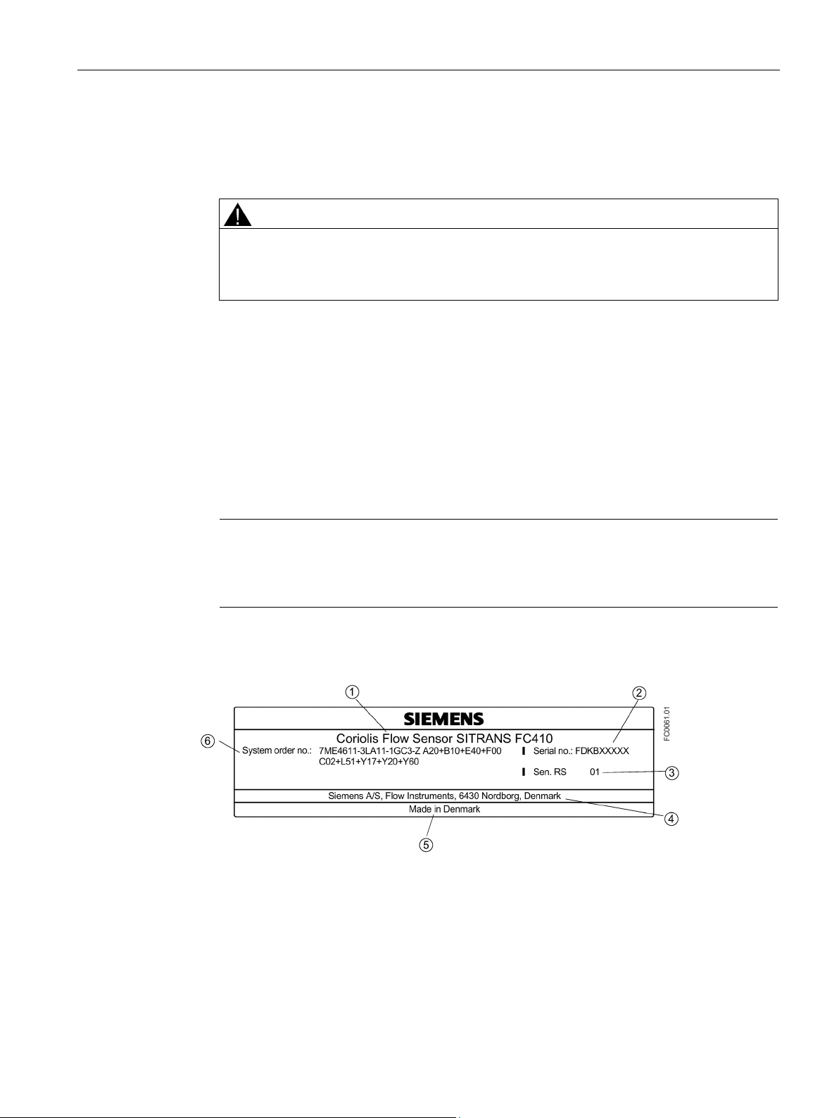
FC410 sensor identification nameplate
①
Product name
Sensor product name
②
Serial no.
Flowmeter serial number
③
Sen. RS
Mechanical sensor version number
④
Manufacturer
Manufacturer name and location
⑤
Country
Manufacturing country
⑥
System order no.
Device-specific system order number
1.4 Device identification
3. Retain damaged parts for clarification.
4. Check the scope of delivery by comparing your order to the shipping documents for
correctness and completeness.
Danger of explosion in hazardous areas.
• Do not use damaged or incomplete devices.
Each part of the FC410 Coriolis flowmeter has three nameplate types showing the following
information:
● product identification
● product specifications
● certificates and approvals
Image 1-1 FC410 identification nameplate example
FC410 with Modbus
Operating Instructions, 02/2016, A5E33120874-AC
9

Introduction
Flowmeter serial number construction
Calendar year (Y)
Code
1950, 1970, 1990, 2010
A
1951, 1971, 1991, 2011
B
1952, 1972, 1992, 2012
C
1953, 1973, 1993, 2013
D
1954, 1974, 1994, 2014
E
1955, 1975, 1995, 2015
F 1956, 1976, 1996, 2016
H (G)
1957, 1977, 1997, 2017
J
1958, 1978, 1998, 2018
K
1959, 1979, 1999, 2019
L
1960, 1980, 2000, 2020
M
1961, 1981, 2001, 2021
N
1962, 1982, 2002, 2022
P
1963, 1983, 2003, 2023
R
1964, 1984, 2004, 2024
S
1965, 1985, 2005, 2025
T
1966, 1986, 2006, 2026
U
1967, 1987, 2007, 2027
V
1968, 1988, 2008, 2028
W
1969, 1989, 2009, 2029
X
Month (M)
Code
January
1
February
2
March
3
April
4
May
5
June
6
July
7
August
8
September
9
1.4 Device identification
The flowmeter serial number is constructed as follows:
PPPYMDDxxxxxx
where
PPP = Production factory (Siemens Flow Instruments: FDK)
Y = Production year (for encryption, see below)
M = Production month (for encryption, see below)
DD = Production date (for encryption, see below)
xxxxxx = Sequential number
Encryption:
FC410 with Modbus
10 Operating Instructions, 02/2016, A5E33120874-AC
Introduction
October
O
November
N
December
D
Date (DD)
Code
Day 1 to 31
01 to 31 (corresponding to the actual date)
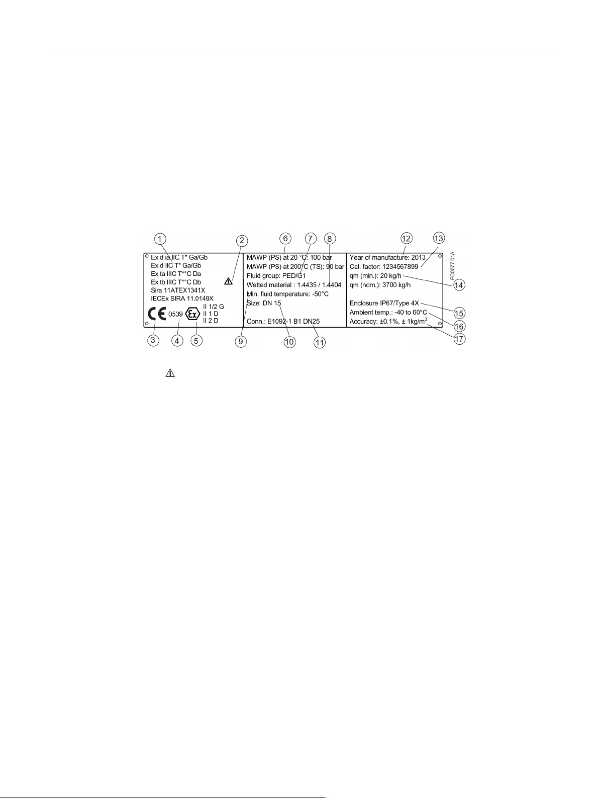
FC410 sensor specification nameplate
①
EX approvals
Ex approval specifications for the sensor (ATEX example)
②
Consult the operating instructions
③
CE
CE mark
④
0539
Notified Body ID (ATEX)
⑤
Ex
Ex mark
⑥
(392 °F) (max. temperature)
⑦
Fluid group
Fluid group statement required by PED
⑧
Wetted material
Tube/process connection materials
⑨
Min. fluid temperature
Minimum fluid temperature
⑩
Size DN
Nominal size
⑪
Conn.
Process connection type and size
⑫
number found on the identification nameplate
⑬
Cal. Factor
Calibration factor
⑭
Qm (nom)
⑮
Enclosure IP
Degree of protection
⑯
Ambient Temp.
Ambient temperature range
⑰
Accuracy
Accuracy for massflow and density
1.4 Device identification
MAWP Maximum allowable working pressures at 20 °C (68 °F) and 200 °C
Year of Manufacture Manufacturing year
More detailed manufacturing date information is given in the serial
Qm (min)
Image 1-2 FC410 specification nameplate example
Minimum and nominal flows with water at 20 °C (68 °F)
FC410 with Modbus
Operating Instructions, 02/2016, A5E33120874-AC
11
Introduction
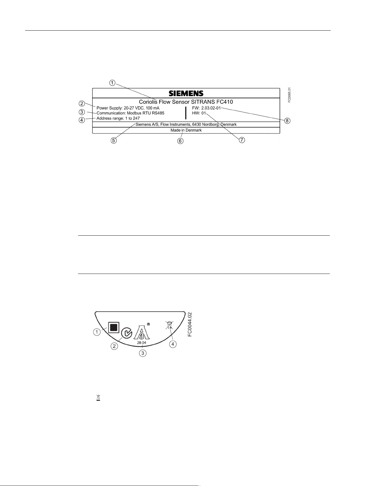
FC410 Mini Flow Link (MFL) identification nameplate
①
Product name
Name of device
②
Power supply
Power supply
③
Communication
Communication: Modbus Master/Slave RTU technology
④
Address range
Modbus device address range
⑤
Manufacturer
Manufacturer name and location
⑥
Country
Manufacturing country
⑦
HW
Hardware version
⑧
FW
Firmware version
Note
Approval identifications
Approval certificates and notified body identifications are available for download at
siemens.com
FC410 sensor approval nameplate
①
QR code
Product-specific QR code
②
C✓
C-tick logo
③
3A
3A logo
④
WEEE (Page 83)
1.4 Device identification
Image 1-3 FC410 Mini Flow Link identification nameplate
Image 1-4 FC410 approval nameplate example
FC410 with Modbus
12 Operating Instructions, 02/2016, A5E33120874-AC

Introduction
Note
Logos and warnings
Logos and warnings are only shown on the product where applicable. The combination
shown in the example above is relevant for a hygienic sensor.
The Australian C
FC410 EHEDG nameplate
Other label
1.4 Device identification
-tick mark is mandatory on all products.
Image 1-5 EHEDG nameplate
This nameplate appears on all Hygienic sensors 7ME462.
Image 1-6 How to install
The QR code provides direct internet connection to
● The product support portal, which includes access to the How to Install YouTube video.
(This example provides that function.)
● Product and production-specific documentation maintained in the production database.
FC410 with Modbus
Operating Instructions, 02/2016, A5E33120874-AC
13

Introduction
1.5
Further Information
Product information on the Internet
Worldwide contact person
1.5 Further Information
The Operating Instructions are available on the documentation disk shipped with the device,
and on the Internet on the Siemens homepage, where further information on the range of
SITRANS F flowmeters may also be found:
Product information on the internet (http://www.siemens.com/flow
If you need more information or have particular problems not covered sufficiently by these
Operating Instructions, get in touch with your contact person. You can find contact
information for your local contact person on the Internet:
Local contact person (http://www.automation.siemens.com/partner
)
)
FC410 with Modbus
14 Operating Instructions, 02/2016, A5E33120874-AC

Safety notes
2
Symbol
Explanation
2.1
Laws and directives
Conformity with European directives
Electromagnetic compatibil
ty EMC
2004/108/EC
Directive of the Europe
approximation of the laws of the Member States relating to
electromagnetic compatibility and repealing Directive
89/336/EEC.
Low voltage directive LVD
2006/95/EC
Directive of the European Parliament and of the Council on the
harmonisation of the laws of Member States relating to electr
cal equipment designed for use within certain voltage limits.
This device left the factory in good working condition. In order to maintain this status and to
ensure safe operation of the device, observe these instructions and all the specifications
relevant to safety.
Observe the information and symbols on the device. Do not remove any information or
symbols from the device. Always keep the information and symbols in a completely legible
state.
Consult operating instructions
Observe the test certification, provisions and laws applicable in your country during
connection, assembly and operation. These include, for example:
● National Electrical Code (NEC - NFPA 70) (USA)
● Canadian Electrical Code (CEC) (Canada)
Further provisions for hazardous area applications are for example:
● IEC 60079-14 (international)
● EN 60079-14 (EC)
The CE marking on the device symbolizes the conformity with the following European
directives:
i-
an Parliament and of the Council on the
i-
FC410 with Modbus
Operating Instructions, 02/2016, A5E33120874-AC
15

Safety notes
Atmosphère explosible
ATEX
94/9/EC
Directive of the European Parlia
approximation of the laws of the Member States concerning
equipment and protective systems intended for use in potentia
ly explosive atmospheres.
Pressure equipment direct
ve PED
97/23/EC
Directive of the European Parliament
approximation of the laws of the Member States concerning
pressure equipment.
WARNING
Improper device modifications
Note
CE declaration
The CE declaration certificate is available on the SensorFlash SD card delivered with the
device.
Note
EAC declaration
The EAC declaration is available on the SensorFlash SD card delivered with the device.
2.2
Installation in hazardous locations
WARNING
Equipment used in hazardous locations
2.2 Installation in hazardous locations
ment and the Council on the
l-
i-
and of the Council on the
The applicable directives can be found in the EC conformity declaration of the specific
device. Further country or region-specific code conformity information is available on
request.
Danger to personnel, system and environment can result from modifications to the device,
particularly in hazardous areas.
• Only carry out modifications that are described in the instructions for the device. Failure
to observe this requirement cancels the manufacturer's warranty and the product
approvals.
Equipment used in hazardous locations must be Ex-approved for the region of installation
and marked accordingly. It is required that the special conditions for safe use provided in
the manual and in the Ex certificate are followed!
FC410 with Modbus
16 Operating Instructions, 02/2016, A5E33120874-AC

Safety notes
Hazardous location approvals
ATEX:
IECEx:
EAC Ex
2.2 Installation in hazardous locations
The device is approved for use in hazardous locations and has the approvals listed below.
Special conditions for safe installation and operation specified by each approval authority are
included in the relevant certificate.
FC410 flowmeter (can be installed in Zone 1 for gas and Zone 20/21 for dust):
Certificate: SIRA 11ATEX1341X
II 1/2 G
1D
2D
For gas:
Ex d ia IIC T* Ga/Gb
Ex d IIC T* Ga/Gb
(Ga/Gb: Zone 0 in pipe and Zone 1 in environment)
For dust:
Ex ta IIIC T* °C Da
Ex tb IIIC T* °C Db
(Zone 20 ("ta") process and ambient temperature limited in comparison with Zone 21 ("tb")
Ta = -40°C to +60°C
* Temperature class (dependent on the process temperature and the ambient temperatur)
FC410 flowmeter (can be installed in Zone 1 for gas and Zone 20/21 for dust):
Certificate: IECEx SIR 11.0149X
For gas:
Ex d ia IIC T* Ga/Gb
Ex d IIC T* Ga/Gb
(Ga/Gb: Zone 0 in pipe and Zone 1 in environment)
For dust:
Ex ta IIIC T* °C Da
Ex tb IIIC T* °C Db
(Zone 20 ("ta") process and ambient temperature limited in comparison with Zone 21 ("tb")
(Ta = -40°C to +60°C)
* Temperature class (dependent on the process temperature and the ambient temperature)
FC410 flowmeter / -40°C ≤ Tamb ≤ ** °C
1Ex d ia IIC T* Ga/Gb
Ex ta IIIC T** °C Da
Ex tb IIIC T** °C Db
FC410 with Modbus
Operating Instructions, 02/2016, A5E33120874-AC
17

Safety notes
FM:
Note
Control drawing
See Control
Maximum temperature specifications for Ex use
Ta (°C)
Maximum Process Temperature per Temperature Class (°C)
T6
T5
T4
T3
60
70
70
70
70
55
85
100
100
100
50
85
100
130
130
45
85
100
135
160
40
85
100
135
190
35
85
100
135
200
30
85
100
135
200
Ta (°C)
Maximum Process Temperature per Temperature Class (°C)
60
70
55
100
50
130
45
160
40
190
35
200
30
200
2.2 Installation in hazardous locations
Sensor with Mini Flow Link (MFL) (FC410):
Class I, II, III Division 1
Groups A, B,C, D, E, F, G
Class I Zone1 and Zone 20/21
drawing: A5E31205486A
Device temperature classification with and without dust is related to the process temperature
and ambient temperature as listed below.
The maximum allowable process fluid temperatures with respect to temperature class for the
device when used with potentially explosive gases in a maximum ambient temperature of
+60°C are:
FC410 with Modbus
18 Operating Instructions, 02/2016, A5E33120874-AC
If the equipment is placed in a "tb" environment (Zone 21), the maximum process
temperatures shall be as follows:
Additionally, the maximum surface temperature of the overall device shall be:
● If Tprocess ≤ 85°C, maximum surface temperature = 85°C.
● If Tprocess > 85°C, maximum surface temperature = process temperature.
Safety notes
Ta (°C)
Maximum Process Temperature per Temperature Class (°C)
60
-40
50
20
40
80
35
110
30
140
Special conditions for safe use
WARNING
Laying of cables
Explosion hazard
WARNING
Field wiring installation
2.2 Installation in hazardous locations
If the equipment is placed in a "ta" environment (Zone 20), the maximum process
temperature shall be as follows:
55 -10
45 50
In general, it is required that:
● The equipment shall not be opened when energized and when an explosive gas or dust
atmosphere may be present..
● Appropriate cable connectors are used.
● Sensor is connected to the potential equalization throughout the hazardous area.
● EN/IEC 60079-14 is considered for installation in hazardous areas.
Further information and instructions including approval-specific special conditions for safe
use in Ex applications can be found in the certificates on the accompanying literature CD
and at www.siemens.com/FC410 (www.siemens.com/FC410
).
Cable for use in hazardous locations must satisfy the requirements for having a proof
voltage of at least 500 V AC applied between the conductor/ground, conductor/shield and
shield/ground.
Connect the devices that are operated in hazardous areas as per the stipulations applicable
in the country of operation.
Ensure that the national requirements of the country in which the devices are installed are
met.
FC410 with Modbus
Operating Instructions, 02/2016, A5E33120874-AC
19

Safety notes
2.3
Certificates
2.3 Certificates
Certificates are posted on the online support portal
(http://www.siemens.com/processinstrumentation/certificates
and can also be found on the documentation disk shipped with the device.
)
Certification documents including calibration report are supplied with each sensor included
on the SensorFlash. Material, pressure test, and factory conformance certificates are
optional at ordering.
FC410 with Modbus
20 Operating Instructions, 02/2016, A5E33120874-AC

Description
3
Measurement of liquids and gases
Main applications
Note
Use in a domestic environment
This is a Class A Group 1 equipment intended for use in industrial areas.
In a domestic environment this device may cause
SITRANS F C Coriolis mass flowmeters are designed for measurement of a variety of liquids
and gases. The flowmeters are multi-parameter devices offering accurate measurement of
massflow, volumeflow, density, temperature and, depending on product variants, fraction,
including industry-specific fractions.
The main applications of the Coriolis flowmeter can be found in all industries, such as:
● Chemical & Pharma: detergents, bulk chemicals, acids, alkalis, pharmaceuticals, blood
products, vaccines, insulin production
● Food & Beverage: dairy products, beer, wine, soft drinks, °Brix/°Plato, fruit juices and
pulps, bottling, CO
● Automotive: fuel injection nozzle & pump testing, filling of AC units, engine consumption,
paint robots
● Oil & Gas: filling of gas bottles, furnace control, test separators, bore-hole plasticizer
dosing, water-cut metering
● Water & Waste Water: dosing of chemicals for water treatment
dosing, CIP/SIP-liquids, mixture recipe control
2
radio interference.
FC410 with Modbus
Operating Instructions, 02/2016, A5E33120874-AC
21

Description
3.1
Design
Flowmeter design
Note
Ex certification requires that the threaded ports always remain closed.
3.1 Design
The SITRANS FC410 flowmeter uses the Coriolis principle to measure flow. The device is a
one channel flowmeter with Modbus RTU RS 485 output.
Image 3-1 Flowmeter - M12 connection
Image 3-2 Flowmeter – terminated cable
All primary process measurement of massflow, volumeflow, density and process
temperature are made in the MFL/sensor front end.
The sensor comprises two parallel bent tubes welded directly to the process connections at
each end via a manifold.
The sensors are available in AISI 316L stainless steel and Hastelloy C22. The enclosure is
made of AISI 304 stainless steel which has a pressure rating of 20 bar (290 psi) for DN 15 to
DN 50 and 17 bar (247 psi) for DN 80. The burst pressure for all sizes is in excess of 160
bar.
The sensor enclosure can be equipped with a pressure guard or flushed with dry inert gas at
the threaded ports for non-hazardous applications only.
The Mini Flow Link is available in an aluminum enclosure with an ingress protection grade of
IP67/NEMA 4X. It has a 4-wire M12 cable or terminated cable connection for communication
and power supply.
FC410 with Modbus
22 Operating Instructions, 02/2016, A5E33120874-AC

Description
Flowmeter overview
①
Mini Flow Link (MFL)
②
Lid-lock
③
Cable feed-through (M12 socket or gland)
④
Plug and threaded port for example for pressure guard
⑤
Sensor enclosure
⑥
Process connections
3.2
System integration
Note
Multidrop installations in hazardous locations
Multidr
device, see illustrations in
3.3
Modbus RTU technology
3.2 System integration
Image 3-3 Overview of FC410 flowmeter
The FC410 flowmeter functions as a Modbus RTU slave with standard Modbus commands
implemented. Setup parameters, process values, diagnostics, and status information are
mapped as Modbus registers.
The device can be connected point-to-point or in a multidrop network in non-hazardous or
hazardous locations. It can be connected to different hosts for example a PLC system or a
PC used as service tool or configuration tool.
op installations in hazardous locations require flameproof conduit seals for each
System configurations (Page 43)
Modbus RTU is an open, serial protocol based on master/slave architecture. The protocol
interconnects field equipment such as sensors, actuators, and controllers and is widely used
in both process and manufacturing automation. The fieldbus environment is the base level
group of digital networks in the hierarchy of plant networks.
FC410 with Modbus
Operating Instructions, 02/2016, A5E33120874-AC
23
Description
Features
Unicast communication mode
Modbus Frame
SLAVE ADDRESS
FUNCTION MODE
DATA
CRC
1 Byte
1 Byte
0 to 252 Bytes
2 Bytes
References
3.3 Modbus RTU technology
The SITRANS F Modbus RTU communication complies with the Modbus Serial Line
Protocol. Among other things this implies a master / slave protocol at level 2 of the OSI
model. A node (the master) issues explicit commands to one of the slave nodes and
processes responses. Slave nodes will not transmit data without a request from the master
node, and do not communicate with other slaves.
Modbus is a mono master system, which means that only one master at a time can be
connected.
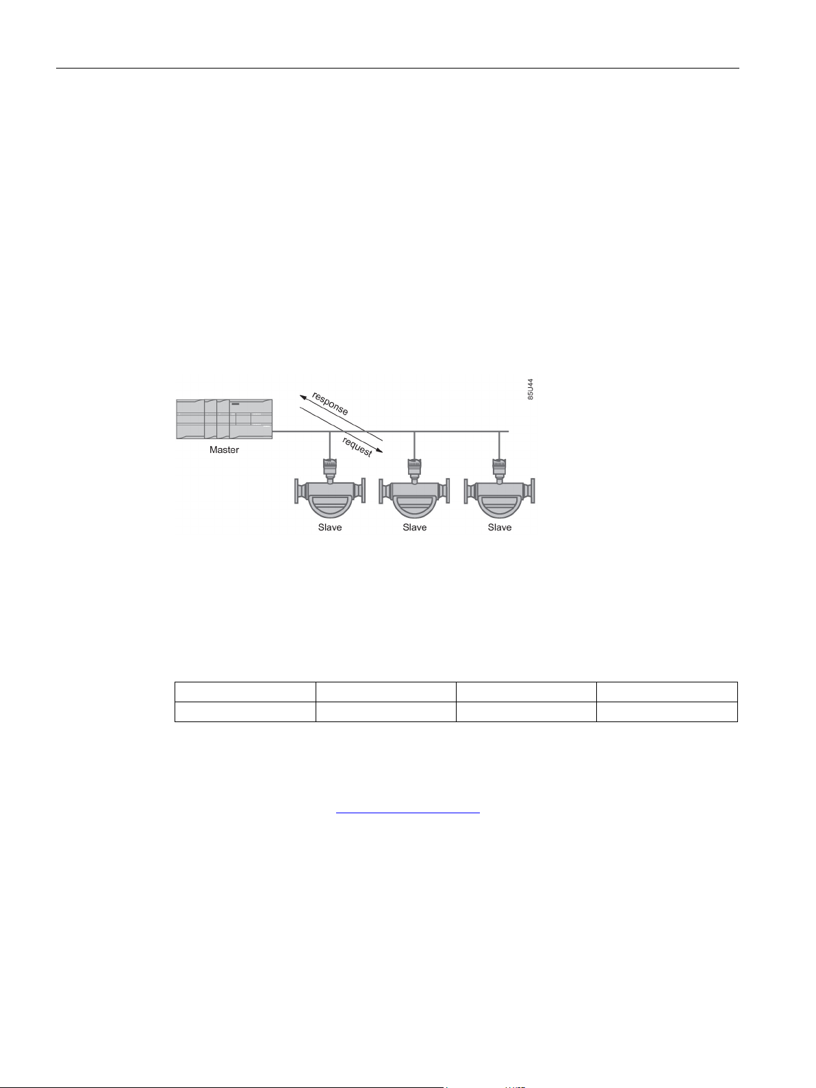
In unicast mode (master/slave mode) the master sends a request to a specific slave device
and waits a specified time for a response.
Image 3-4 Unicast Mode
The Modbus frame is shown below and is valid for both requests and responses.
Table 3- 1 Modbus Frame
For further information, please refer to the following specification and guidelines available at
the Modbus Organization (http://www.modbus.org/
) website
1. Serial Line Specification & Implementation guide
2. Application Protocol Specification
FC410 with Modbus
24 Operating Instructions, 02/2016, A5E33120874-AC

Description
3.4
Features
3.5
Theory of operation
The Coriolis principle of measurement
3.4 Features
● The SITRANS FC410 can be used as Modbus slave in stand-alone or parallel operation
on Modbus or third party automation systems
● Compact sensor design
● NAMUR conforming sensor built-in lengths (on request)
● High immunity against process noise
● Fast response to step changes in flow
● High update rate (100 Hz) on all process values
● Measurement of:
– Massflow
– Volumeflow
– Density
– Process media temperature
● Independent low flow cut-off settings for massflow and volumeflow
● Automatic zero-point adjustment (initiated by host system)
● Process noise damping using digital signal processing (DSP).
● One totalizer for summation of massflow. The totalizer is reset on loss of power.
● Empty pipe monitoring
● Simulation of process values:
– Massflow
– Volumeflow
– Density
– Process media temperature
● Troubleshooting and sensor checking
● Use in hazardous locations according to specification
The flow measurement is based on the Coriolis law of motion. Particles moving in a rotating /
oscillating system will resist imposed oscillations in a manner consistent with their mass and
velocity (momentum). Oscillation produced by a Coriolis flowmeter where the process media
is accelerated around bends results in phase distortions of the measuring tubes.
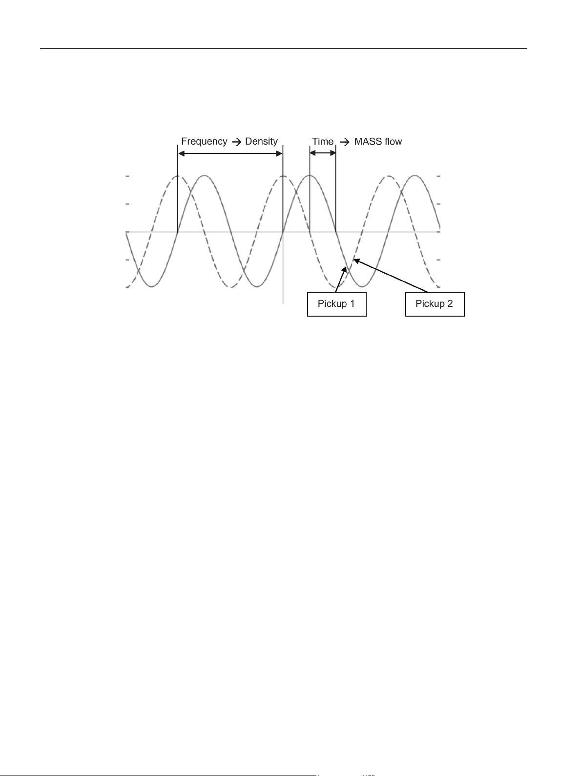
The SITRANS F C sensors are energized by an electromagnetic (voice coil) driver circuit
which oscillates the pipes at their resonant frequency. Two pickups are placed symmetrically
on either side of the driver to provide position signals for digital processing.
FC410 with Modbus
Operating Instructions, 02/2016, A5E33120874-AC
25
Description
Digital signal processing (DSP)
3.5 Theory of operation
When the media flows through the sensor, Coriolis force will act on the measuring tubes and
cause deflection which can be measured as a phase shift between Pickup 1 and Pickup 2.
The phase shift is proportional to the mass flowrate.
The frequency (or period) of the vibration is a direct function of the process media density.
The frequency and amplitude of the driver is regulated to ensure a stable output from the 2
pickups. The temperature of the sensor tubes is measured to provide accurate
compensation for changes in the material stiffness. As a result the process media
temperature is also accurately measured.
The flow proportional phase signal from the pickups, the temperature measurement and the
driver frequency enable calculation and reporting of mass, density, volume, and temperature.
The analog to digital conversion takes place in an ultra low noise sigma delta converter with
high signal resolution. With fast digital signal processing massflow and density values are
calculated using a patented DFT technology (Discrete Fourier Transformation). The
combination of this patented DFT technology and the fast DSP enables short response time
(< 10 ms) to changes in the measured values.
The built-in noise filter is configurable and can be used for improving the performance of the
flowmeter, in case the installation and application conditions are not ideal. Typical process
noise such as gas bubbles (two-phase-flow) can be reduced through the filter functions.
FC410 with Modbus
26 Operating Instructions, 02/2016, A5E33120874-AC
Installing/Mounting
4
WARNING
Installation in hazardous location
4.1
Flowmeter installation
4.1.1
Installation safety precautions
WARNING
High pressure hazard
WARNING
Exceeded maximum permissible operating pressure
SITRANS F flowmeters with minimum IP67/NEMA 4X enclosure rating are suitable for indoor
and outdoor installations.
● Make sure that specifications for rated process pressure (PS) and media temperature
(TS) plus ambient temperature that are indicated on the device nameplate / label will not
be exceeded.
Special requirements apply to the location and installation of the device. See Installation
in hazardous locations (Page 16).
In applications with working pressures/media that can be dangerous to people,
surroundings, equipment or others in case of pipe fracture, we recommend that special
precautions such as special placement, shielding or installation of a pressure guard or a
safety valve are taken when the flowmeter is mounted.
Danger of injury or poisoning.
The maximum permissible operating pressure depends on the device version. The device
can be damaged if the operating pressure is exceeded. Hot, toxic and corrosive process
media could be released.
• Make sure that the device is suitable for the maximum permissible operating pressure of
your system. Refer to the information on the nameplate and/or in "Rated operating
conditions (Page 94)".
FC410 with Modbus
Operating Instructions, 02/2016, A5E33120874-AC
27

Installing/Mounting
CAUTION
Hot surfaces resulting from hot process media
CAUTION
External stresses and loads
WARNING
Wetted parts unsuitable for the process media
Note
Material compatibility
Siemens can provide you with support concerning selection of sensor components wetted by
process media. However, you are responsible for the selection of components. Siemens
accepts no liability for faults or failures resulting from incompatible materials.
4.1.2
Determining a location
CAUTION
Electromagnetic fields
4.1 Flowmeter installation
Danger of burns resulting from surface temperatures above 70 °C (155 °F).
• Take appropriate protective measures, for example contact protection.
• Make sure that protective measures do not cause the maximum permissible ambient
temperature to be exceeded. Refer to the information in Chapter "Rated operating
conditions (Page 94)".
Damage to device by severe external stresses and loads (e.g. thermal expansion or pipe
tension). Process media can be released.
• Prevent severe external stresses and loads from acting on the device.
Danger of injury or damage to device.
Hot, toxic and corrosive media could be released if the process medium is unsuitable for
the wetted parts.
• Ensure that the material of the device parts wetted by the process medium is suitable for
the medium. Refer to the information in "Technical data" (Page 99).
Do not install the flowmeter in the vicinity of strong electromagnetic fields, for example near
motors, variable frequency drives, transformers etc.
FC410 with Modbus
28 Operating Instructions, 02/2016, A5E33120874-AC
 Loading...