

Siemens SITRANS FC330 Operating Instructions Manual

SITRANS F
Coriolis Flowmeters
SITRANS FC330
7ME4633 (SITRANS FC330)
Introduction
1
Operating Instructions
Safety notes
Description
Installing/mounting
Connecting
Commissioning
Operating
Parameter assignment
2
3
4
5
6
7
8
Service and maintenance
Diagnostics and
troubleshooting
Technical data
Dimension drawings
Technical reference
HART communication
HMI menu structure
9
10
11
12
A
B
C
01/2019
A5E44030648-AB
Zero point adjustment
Certificates and support
D
E

Legal information
Warning notice system
This manual contains notices you have to observe in order to ensure your personal safety, as well as to prevent
damage to property. The notices referring to your personal safety are highlighted in the manual by a safety alert
symbol, notices referring only to property damage have no safety alert symbol. These notices shown below are
graded according to the degree of danger.
DANGER
indicates that death or severe personal injury will result if proper precautions are not taken.
WARNING
indicates that death or severe personal injury may result if proper precautions are not taken.
CAUTION
indicates that minor personal injury can result if proper precautions are not taken.
NOTICE
indicates that property damage can result if proper precautions are not taken.
If more than one degree of danger is present, the warning notice representing the highest degree of danger will be
used. A notice warning of injury to persons with a safety alert symbol may also include a warning relating to property
damage.
Qualified Personnel
The product/system described in this documentation may be operated only by personnel qualified for the specific
task in accordance with the relevant documentation, in particular its warning notices and safety instructions. Qualified
personnel are those who, based on their training and experience, are capable of identifying risks and avoiding
potential hazards when working with these products/systems.
Proper use of Siemens products
Note the following:
WARNING
Siemens products may only be used for the applications described in the catalog and in the relevant technical
documentation. If products and components from other manufacturers are used, these must be recommended or
approved by Siemens. Proper transport, storage, installation, assembly, commissioning, operation and
maintenance are required to ensure that the products operate safely and without any problems. The permissible
ambient conditions must be complied with. The information in the relevant documentation must be observed.
Trademarks
All names identified by ® are registered trademarks of Siemens AG. The remaining trademarks in this publication
may be trademarks whose use by third parties for their own purposes could violate the rights of the owner.
Disclaimer of Liability
We have reviewed the contents of this publication to ensure consistency with the hardware and software described.
Since variance cannot be precluded entirely, we cannot guarantee full consistency. However, the information in this
publication is reviewed regularly and any necessary corrections are included in subsequent editions.
Siemens AG
Division Process Industries and Drives
Postfach 48 48
90026 NÜRNBERG
GERMANY
Document order number: A5E44030648
Ⓟ 02/2019 Subject to change
Copyright © Siemens AG 2019.
All rights reserved

Table of contents
1 Introduction...................................................................................................................................................9
1.1 Purpose of this documentation.................................................................................................9
1.2 Document history .....................................................................................................................9
1.3 Product compatibility ..............................................................................................................10
1.4 Items supplied ........................................................................................................................10
1.5 Checking the consignment.....................................................................................................12
1.6 Security information ...............................................................................................................12
1.7 Transportation and storage ....................................................................................................13
1.8 Notes on warranty ..................................................................................................................13
2 Safety notes................................................................................................................................................15
2.1 Preconditions for use .............................................................................................................15
2.2 Laws and directives................................................................................................................15
2.2.1 FCC Conformity .....................................................................................................................16
2.2.2 Conformity with European directives......................................................................................16
2.3 Requirements for special applications ...................................................................................17
2.4 Use in hazardous areas .........................................................................................................17
2.4.1 Installation in hazardous areas ..............................................................................................19
2.4.2 Maximum temperature specifications for use in hazardous areas .........................................20
3 Description..................................................................................................................................................21
3.1 Overview ................................................................................................................................21
3.2 Design ....................................................................................................................................22
3.2.1 Versions .................................................................................................................................22
3.2.2 Sensor design ........................................................................................................................23
3.2.3 Transmitter design .................................................................................................................24
3.2.4 Wall mount housing transmitter exploded view......................................................................26
3.3 Device identification ...............................................................................................................27
3.4 Approvals ...............................................................................................................................32
3.5 Features .................................................................................................................................33
3.6 Applications............................................................................................................................35
4 Installing/mounting......................................................................................................................................37
4.1 Basic safety notes ..................................................................................................................37
4.1.1 Installation location requirements...........................................................................................39
4.1.2 Proper mounting.....................................................................................................................40
4.2 Installation instructions...........................................................................................................41
4.2.1 Transmitter installation ...........................................................................................................41
SITRANS FC330
Operating Instructions, 01/2019, A5E44030648-AB 3

Table of contents
4.2.1.1 Remote field mount ................................................................................................................41
4.2.1.2 Wall mount housing................................................................................................................42
4.2.1.3 Turning the transmitter (compact version) .............................................................................45
4.2.1.4 Turning the transmitter (remote version)................................................................................46
4.2.1.5 Turning the local display ........................................................................................................48
4.2.2 Sensor installation..................................................................................................................49
4.2.2.1 Determining a location ..........................................................................................................49
4.2.2.2 Orientation of the sensor........................................................................................................50
4.2.2.3 Installation in a drop line ........................................................................................................52
4.2.2.4 Mounting the sensor...............................................................................................................52
4.2.2.5 Hydrostatic testing..................................................................................................................54
4.2.2.6 Installing with insulation .........................................................................................................54
4.3 Disassembly...........................................................................................................................55
5 Connecting .................................................................................................................................................57
5.1 Basic safety notes ..................................................................................................................57
5.2 Connecting FC330 .................................................................................................................60
5.2.1 Cable requirements................................................................................................................61
5.2.2 Transmitter power supply and I/Os connection......................................................................62
5.2.2.1 Connecting the DSL and the transmitter ................................................................................62
5.2.2.2 Preparing for the transmitter connections ..............................................................................65
5.2.2.3 Connecting the Current HART, CH1 ......................................................................................67
5.2.2.4 Connecting the Modbus (CH1)...............................................................................................69
5.2.2.5 Connecting the Profibus (CH1) ..............................................................................................71
5.2.2.6 Connecting channels 2 to 4....................................................................................................72
5.2.2.7 Input/output configuration.......................................................................................................74
5.2.2.8 Connecting the power supply - Field mount...........................................................................75
5.2.2.9 Connecting the power supply - Wall mount............................................................................77
5.2.2.10 Finishing the transmitter connection ......................................................................................78
5.3 Instructions specific to hazardous area installations ..............................................................79
5.3.1 Wiring in hazardous areas .....................................................................................................79
6 Commissioning ...........................................................................................................................................81
6.1 Basic safety notes ..................................................................................................................81
6.1.1 Warnings ................................................................................................................................83
6.2 General requirements ............................................................................................................84
6.3 Local commissioning via HMI.................................................................................................84
6.3.1 Local display ..........................................................................................................................84
6.3.2 Wizard introduction ................................................................................................................85
6.3.3 Initial startup...........................................................................................................................85
6.3.4 Zero point adjustment ............................................................................................................86
6.3.5 Wizards ..................................................................................................................................88
6.3.5.1 Quick commissioning wizard (menu item 1.1)........................................................................88
6.3.5.2 Zero point adjustment wizard (menu item 1.2).......................................................................90
6.3.5.3 Process values wizard (menu item 1.3) .................................................................................92
6.3.5.4 Inputs and outputs wizard (menu item 1.4) ............................................................................94
6.3.5.5 Gas application wizard (menu item 1.5).................................................................................99
6.3.5.6 Pulsating flow wizard (menu item 1.6) .................................................................................100
6.3.5.7 Dosing application wizard (menu item 1.7) ..........................................................................101
SITRANS FC330
4 Operating Instructions, 01/2019, A5E44030648-AB

Table of contents
6.4 Remote commissioning with PDM .......................................................................................102
7 Operating..................................................................................................................................................103
7.1 Local operation (HMI)...........................................................................................................103
7.1.1 Display view structure ..........................................................................................................104
7.1.2 Access control......................................................................................................................109
7.1.3 Operation view .....................................................................................................................110
7.1.4 Measurement views .............................................................................................................111
7.1.5 Operating views ...................................................................................................................114
7.1.6 Alarm views..........................................................................................................................115
7.1.7 Diagnostic views ..................................................................................................................117
7.1.8 Navigation view ....................................................................................................................117
7.1.9 Parameter view ....................................................................................................................119
7.2 Remote operation.................................................................................................................123
7.2.1 Overview of device configuration software...........................................................................123
7.2.2 SIMATIC PDM......................................................................................................................123
8 Parameter assignment .............................................................................................................................127
8.1 Upper scaling settings..........................................................................................................127
8.2 Functions..............................................................................................................................127
8.2.1 Process values.....................................................................................................................127
8.2.2 Zero point adjustment ..........................................................................................................131
8.2.3 Low flow cut-off ....................................................................................................................132
8.2.4 Empty tube monitoring .........................................................................................................132
8.2.5 Process noise damping........................................................................................................133
8.2.6 Inputs and outputs................................................................................................................134
8.2.6.1 Current output ......................................................................................................................135
8.2.6.2 Pulse output .........................................................................................................................140
8.2.6.3 Frequency output .................................................................................................................141
8.2.6.4 Redundancy mode (frequency)............................................................................................142
8.2.6.5 Digital output ........................................................................................................................144
8.2.6.6 Input .....................................................................................................................................144
8.2.7 Totalizers..............................................................................................................................145
8.2.8 Dosing ..................................................................................................................................145
8.2.8.1 Dosing control configuration.................................................................................................147
8.2.8.2 Valve control configuration...................................................................................................148
8.2.8.3 Dosing operation ..................................................................................................................153
8.2.8.4 Fault handling.......................................................................................................................153
8.2.9 Audit trail logging..................................................................................................................154
8.2.10 Diagnostic log.......................................................................................................................154
8.2.11 Custom unit ..........................................................................................................................155
8.2.12 SensorFlash .........................................................................................................................155
8.2.13 Datalogging on SensorFlash................................................................................................156
8.2.14 Process peak values on SensorFlash..................................................................................156
8.2.15 Simulation ............................................................................................................................156
8.2.16 Maintenance.........................................................................................................................157
9 Service and maintenance .........................................................................................................................159
9.1 Basic safety notes ................................................................................................................159
9.2 Recalibration ........................................................................................................................160
SITRANS FC330
Operating Instructions, 01/2019, A5E44030648-AB 5

Table of contents
9.3 Cleaning ...............................................................................................................................160
9.4 Maintenance and repair work...............................................................................................161
9.4.1 Service information ..............................................................................................................164
9.5 Replacing the device............................................................................................................165
9.6 Ordering of spare parts ........................................................................................................165
9.7 Return procedure .................................................................................................................165
9.8 Disposal ...............................................................................................................................166
9.9 Ex-approved products ..........................................................................................................166
10 Diagnostics and troubleshooting ..............................................................................................................167
10.1 Device status symbols .........................................................................................................167
10.2 Fault codes and corrective actions.......................................................................................171
10.2.1 Sensor diagnostics...............................................................................................................171
10.2.2 Transmitter diagnostics ........................................................................................................176
10.3 Operation troubleshooting....................................................................................................189
10.3.1 Copying the application setup from one device to another ..................................................189
10.3.2 Updating the firmware ..........................................................................................................189
10.3.3 Troubleshooting sensor-related problems............................................................................190
11 Technical data ..........................................................................................................................................195
11.1 Power ...................................................................................................................................195
11.2 Performance.........................................................................................................................195
11.3 Interface ...............................................................................................................................197
11.3.1 Modbus interface..................................................................................................................197
11.3.2 HART interface.....................................................................................................................197
11.4 Inputs ...................................................................................................................................198
11.5 Outputs.................................................................................................................................198
11.6 Construction .........................................................................................................................200
11.6.1 Sensor design ......................................................................................................................201
11.6.2 Sensor cable specifications HART.......................................................................................202
11.7 Operating conditions ............................................................................................................204
11.8 Process variables.................................................................................................................205
11.9 Bus communication..............................................................................................................205
11.10 Certificates and approvals....................................................................................................206
11.11 SensorFlash .........................................................................................................................206
11.12 PED......................................................................................................................................207
11.13 Pressure - temperature ratings ............................................................................................211
11.13.1 Pressure - temperature ratings (stainless steel sensors) .....................................................212
11.13.2 Pressure - temperature ratings (nickel alloy sensors) ..........................................................214
12 Dimension drawings .................................................................................................................................217
12.1 Sensor dimensions...............................................................................................................217
SITRANS FC330
6 Operating Instructions, 01/2019, A5E44030648-AB

Table of contents
12.2 316L stainless steel - standard ............................................................................................218
12.3 316L stainless steel polished - hygienic versions ................................................................219
12.4 Nickel alloy ...........................................................................................................................220
12.5 Transmitter dimensions........................................................................................................221
12.6 Wall mount enclosure dimensions .......................................................................................222
12.7 Mounting bracket dimensions ..............................................................................................223
A Technical reference ..................................................................................................................................225
A.1 Theory of operation ..............................................................................................................225
A.2 Sensor dimension dependent default settings .....................................................................226
A.2.1 Mass flow: Sensor dimension dependent default settings (Process values) .......................226
A.2.2 Standard volume flow: Sensor dimension dependent default settings (Process values).....228
A.2.3 Volume flow: Sensor dimension dependent default settings (Process values)....................229
A.2.4 Fraction: Sensor dimension dependent default settings (Process values) ..........................231
A.2.5 Zero point adjustment: Sensor dimension dependent default settings (Process values).....233
B HART communication...............................................................................................................................235
B.1 Mode of operation HART function........................................................................................235
C HMI menu structure ..................................................................................................................................237
C.1 Main menu ...........................................................................................................................237
C.2 Menu item 2.1: Sensor.........................................................................................................239
C.3 Menu item 2.2: Process values............................................................................................239
C.4 Menu item 2.3: Totalizers.....................................................................................................243
C.5 Menu item 2.4: Inputs and outputs.......................................................................................244
C.6 Menu item 2.5: Dosing .........................................................................................................251
C.7 Menu item 2.7: Date and time..............................................................................................256
C.8 Menu item 2.8: Local display................................................................................................257
C.9 Menu item 3.1: Identification ................................................................................................259
C.10 Menu item 3.2: Diagnostic events ........................................................................................260
C.11 Menu item 3.3: Maintenance................................................................................................261
C.12 Menu item 3.4: Diagnostics..................................................................................................261
C.13 Menu item 3.5: Peak values.................................................................................................263
C.14 Menu item 3.6: Characteristics.............................................................................................263
C.15 Menu item 3.7: SensorFlash ................................................................................................264
C.16 Menu item 3.8: Simulation....................................................................................................265
C.17 Menu item 3.9: Audit trail .....................................................................................................266
C.18 Menu item 3.10: Self test .....................................................................................................266
C.19 Menu item 3.11: Resets .......................................................................................................267
SITRANS FC330
Operating Instructions, 01/2019, A5E44030648-AB 7

Table of contents
C.20 Menu item 3.12: Firmware update .......................................................................................267
C.21 Menu item 4: Communication ..............................................................................................267
C.22 Menu item 5: Security ..........................................................................................................270
D Zero point adjustment ...............................................................................................................................271
E Certificates and support............................................................................................................................275
E.1 Certificates ...........................................................................................................................275
E.2 QR code label ......................................................................................................................275
E.3 Technical support.................................................................................................................275
Index.........................................................................................................................................................277
SITRANS FC330
8 Operating Instructions, 01/2019, A5E44030648-AB

Introduction
This document is delivered as standard in electronic media with the device. The latest version
can be downloaded at www.siemens.com (www.siemens.com).
1.1 Purpose of this documentation
These instructions contain all information required to commission and use the device. Read the
instructions carefully prior to installation and commissioning. In order to use the device
correctly, first review its principle of operation.
The instructions are aimed at persons mechanically installing the device, connecting it
electronically, configuring the parameters and commissioning it, as well as service and
maintenance engineers.
See also
Certificates (Page 275)
Technical support (Page 275)
QR code label (Page 275)
1
1.2 Document history
The following table shows major changes in the documentation compared to the previous
edition.
The most important changes in the documentation when compared with the respective
previous edition are given in the following table.
Edition Note
01/2019 Second edition
● Chapter Technical data (Page 195) updated
● Chapter Diagnostics and troubleshooting (Page 167) updated
● Appendix HMI menu structure (Page 237) updated
● Overall revision of chapters and contents
06/2018 First edition
SITRANS FC330
Operating Instructions, 01/2019, A5E44030648-AB 9

Introduction
1.4 Items supplied
NOTICE
Use in a domestic environment
This Class A Group 1 equipment is intended for use in industrial areas.
In a domestic environment this device may cause radio interference.
1.3 Product compatibility
Edition Remarks Product compatibility Compatibility of device integration package
01/2019 Manual con‐
tent updated
06/2018 New hardware
New sensor
sizes
HW revision 03
Compact FW revision 4.xx.xx-xx
Remote FW revision 4.xx.xx-xx
HW revision 03
Compact FW revision 4.xx.xx-xx
Remote FW revision 4.xx.xx-xx
Service channel: SIMATIC
V8.2 Service Pack 1 or later
Modbus: SIMATIC V8.2 Serv‐
ice Pack 1 or later
HART: SIMATIC V8.2 Serv‐
ice Pack 1 or later
HART: SITRANS DTM V4.1 5.00.xx-xx
HART: AMS Device manager
V12
PROFIBUS: SIMATIC V8.2
Service Pack 1 or later
PROFIBUS: AMS Device
manager V12
PROFIBUS : SITRANS DTM
V4.1
5.00.xx-xx
5.00.xx-xx
5.00.xx-xx
5.00.xx-xx
1.00.xx-xx
1.00.xx-xx
1.00.xx-xx
5.00.xx-xx
5.00.xx-xx
5.00.xx-xx
5.00.xx-xx
1.00.xx-xx
1.00.xx-xx
1.00.xx-xx
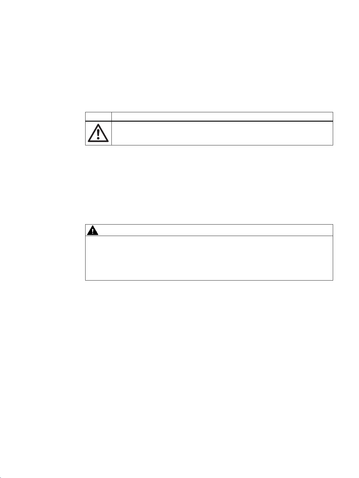
1.4 Items supplied
The device can be delivered as either a compact or a remote system.
SITRANS FC330
10 Operating Instructions, 01/2019, A5E44030648-AB
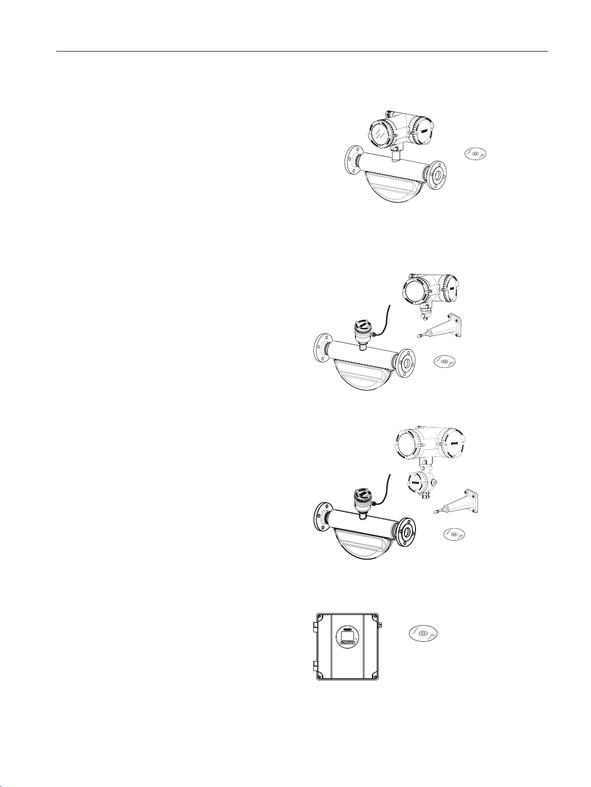
Compact system
● SITRANS FC330 sensor and compact
● DVD containing software, certificates and
Field mount system
Remote with M12 plug connection
● SITRANS FCS300 sensor
● SITRANS FCT030 transmitter with
● Mounting bracket and cushion pad
● Sensor cable
● DVD containing software,
Introduction
1.4 Items supplied
mounted transmitter
device manuals
M12 socket assembled
certificates and device manuals
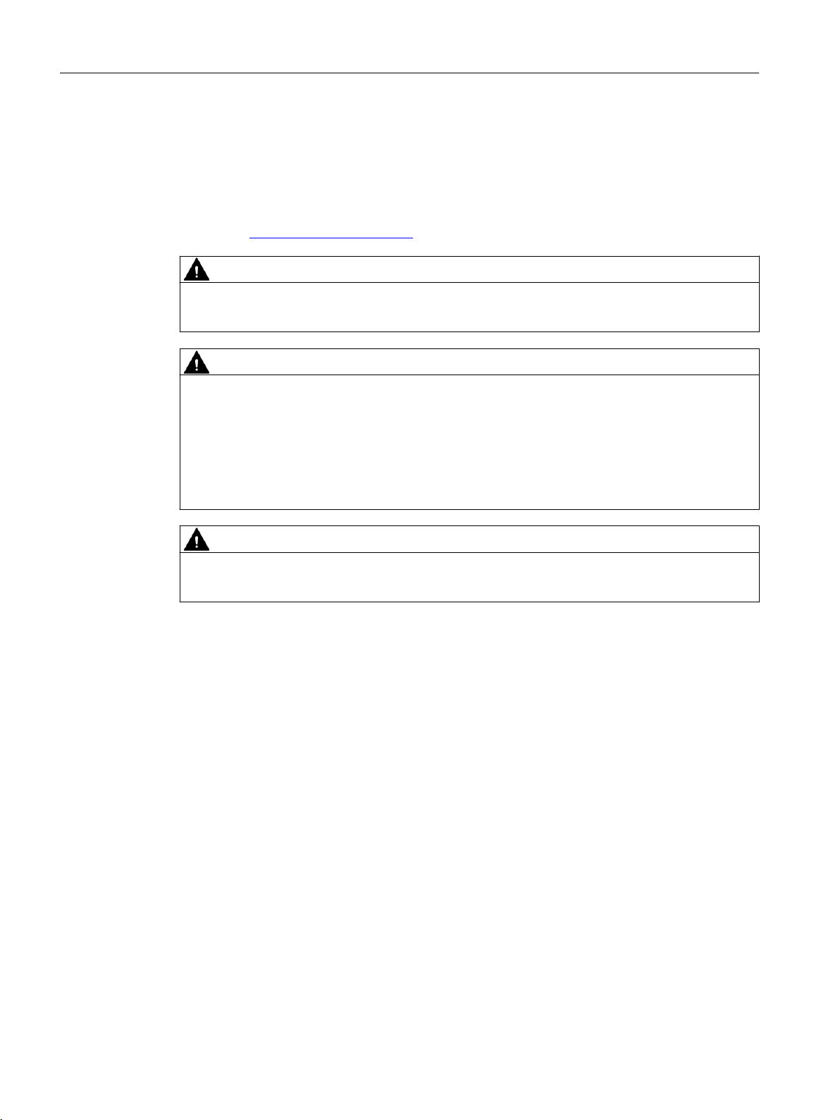
Remote with sensor terminal housing
● SITRANS FCS300 sensor
● SITRANS FCT030 transmitter with
terminal housing assembled
● Mounting bracket and cushion pad
● Sensor cable
● DVD containing software,
certificates and device manuals
Wall mount housing transmitter
● SITRANS FCT030 wall mount
housing transmitter
● DVD containing software,
certificates and device manuals
SITRANS FC330
Operating Instructions, 01/2019, A5E44030648-AB 11

Introduction
1.6 Security information
Note
Supplementary information
Supplementary product and production specific certificates are included on the SensorFlash®
SD card in the transmitter socket.
Note
Scope of delivery may vary, depending on version and add-ons. Make sure the scope of
delivery and the information on the nameplate correspond to your order and the delivery note.
1.5 Checking the consignment
1. Check the packaging and the delivered items for visible damages.
2. Report any claims for damages immediately to the shipping company.
3. Retain damaged parts for clarification.
4. Check the scope of delivery by comparing your order to the shipping documents for
correctness and completeness.
WARNING
Using a damaged or incomplete device
Risk of explosion in hazardous areas.
● Do not use damaged or incomplete devices.
1.6 Security information
Siemens provides products and solutions with industrial security functions that support the
secure operation of plants, systems, machines and networks.
In order to protect plants, systems, machines and networks against cyber threats, it is
necessary to implement – and continuously maintain – a holistic, state-of-the-art industrial
security concept. Siemens’ products and solutions constitute one element of such a concept.
Customers are responsible for preventing unauthorized access to their plants, systems,
machines and networks. Such systems, machines and components should only be connected
to an enterprise network or the internet if and to the extent such a connection is necessary and
only when appropriate security measures (e.g. firewalls and/or network segmentation) are in
place.
For additional information on industrial security measures that may be implemented, please
visit
https://www.siemens.com/industrialsecurity.
Siemens’ products and solutions undergo continuous development to make them more secure.
Siemens strongly recommends that product updates are applied as soon as they are available
and that the latest product versions are used. Use of product versions that are no longer
SITRANS FC330
12 Operating Instructions, 01/2019, A5E44030648-AB

supported, and failure to apply the latest updates may increase customer’s exposure to cyber
threats.
To stay informed about product updates, subscribe to the Siemens Industrial Security RSS
Feed under
https://www.siemens.com/industrialsecurity.
1.7 Transportation and storage
To guarantee sufficient protection during transport and storage, observe the following:
● Keep the original packaging for subsequent transportation.
● Devices/replacement parts should be returned in their original packaging.
● If the original packaging is no longer available, ensure that all shipments are properly
packaged to provide sufficient protection during transport. Siemens cannot assume liability
for any costs associated with transportation damages.
NOTICE
Insufficient protection during storage
Introduction
1.8 Notes on warranty
The packaging only provides limited protection against moisture and infiltration.
● Provide additional packaging as necessary.
Special conditions for storage and transportation of the device are listed in Technical data
(Page 195).
1.8 Notes on warranty
The contents of this manual shall not become part of or modify any prior or existing agreement,
commitment or legal relationship. The sales contract contains all obligations on the part of
Siemens as well as the complete and solely applicable warranty conditions. Any statements
regarding device versions described in the manual do not create new warranties or modify the
existing warranty.
The content reflects the technical status at the time of publishing. Siemens reserves the right
to make technical changes in the course of further development.
SITRANS FC330
Operating Instructions, 01/2019, A5E44030648-AB 13

Introduction
1.8 Notes on warranty
SITRANS FC330
14 Operating Instructions, 01/2019, A5E44030648-AB
Safety notes
2.1 Preconditions for use
Symbol Explanation
Consult operating instructions
This device left the factory in good working condition. In order to maintain this status and to
ensure safe operation of the device, observe these instructions and all the specifications
relevant to safety.
Observe the information and symbols on the device. Do not remove any information or symbols
from the device. Always keep the information and symbols in a completely legible state.
Use the device only for flow measurement in accordance with this operating instructions and
observe the technical data (Page 195).
WARNING
2
Improper device modifications
Risk to personnel, system and environment can result from modifications to the device,
particularly in hazardous areas.
● Only carry out modifications that are described in the instructions for the device. Failure to
observe this requirement cancels the manufacturer's warranty and the product approvals.
2.2 Laws and directives
Observe the safety rules, provisions and laws applicable in your country during connection,
assembly and operation. These include, for example:
● National Electrical Code (NEC - NFPA 70) (USA)
● Canadian Electrical Code (CEC) (Canada)
Further provisions for hazardous area applications are for example:
● IEC 60079-14 (international)
● EN 60079-14 (EU)
SITRANS FC330
Operating Instructions, 01/2019, A5E44030648-AB 15

$
Safety notes
2.2 Laws and directives
2.2.1 FCC Conformity
US Installations only: Federal Communications Commission (FCC) rules
Note
● This equipment has been tested and found to comply with the limits for a Class A digital
device, pursuant to Part 15 of the FCC Rules. These limits are designed to provide
reasonable protection against harmful interference when the equipment is operated in a
commercial environment.
● This equipment generates, uses, and can radiate radio frequency energy and, if not installed
and used in accordance with the operating instructions, may cause harmful interference to
radio communications. Operation of this equipment in a residential area is likely to cause
harmful interference to radio communications, in which case the user will be required to
correct the interference at his own expense.
Observe the test certification, provisions and laws applicable in your country during connection,
assembly and operation. These include, for example:
● National Electrical Code (NEC - NFPA 70) (USA)
● Canadian Electrical Code (CEC) (Canada)
Further provisions for hazardous area applications are for example:
● IEC 60079-14 (international)
● EN 60079-14 (EU)
● For Korea only:
2.2.2 Conformity with European directives
The CE marking on the device symbolizes the conformity with the following European
directives:
Electromagnetic
compatibility EMC
2014/30/EU
Low voltage direc‐
tive LVD
2014/35/EU
Atmosphère explosi‐
ble ATEX
2014/34/EU
Directive of the European Parliament and of the Council on the harmoni‐
sation of the laws of the Member States relating to electromagnetic com‐
patibility
Directive of the European Parliament and of the Council on the harmoni‐
sation of the laws of the Member States relating to the making available
on the market of electrical equipment designed for use within certain volt‐
age limits
Directive of the European Parliament and the Council on the harmonisa‐
tion of the laws of the Member States relating to equipment and protective
systems intended for use in potentially explosive atmospheres
SITRANS FC330
16 Operating Instructions, 01/2019, A5E44030648-AB

Safety notes
2.4 Use in hazardous areas
Pressure equipment
directive PED
2014/68/EU
2011/65/EU RoHS Directive of the European Parliament and the Council on the restriction of
The applicable directives can be found in the EC conformity declaration of the specific device.
Note
CE declaration
The CE declaration certificate is available on the SensorFlash SD card delivered with the
device.
Directive of the European Parliament and of the Council on the approxi‐
mation of the laws of the Member States concerning pressure equipment
the use of certain hazardous substances in electrical and electronic
equipment
See also
Certificates (http://www.siemens.com/processinstrumentation/certificates)
2.3 Requirements for special applications
Due to the large number of possible applications, each detail of the described device versions
for each possible scenario during commissioning, operation, maintenance or operation in
systems cannot be considered in the instructions. If you need additional information not
covered by these instructions, contact your local Siemens office or company representative.
Note
Operation under special ambient conditions
We highly recommend that you contact your Siemens representative or our application
department before you operate the device under special ambient conditions as can be
encountered in nuclear power plants or when the device is used for research and development
purposes.
2.4 Use in hazardous areas
Special conditions for safe use
In general, it is required that:
● EN/IEC 60079-14 is considered for installation in hazardous areas.
● Appropriate cable connectors are used.
SITRANS FC330
Operating Instructions, 01/2019, A5E44030648-AB 17
Safety notes
2.4 Use in hazardous areas
● Sensor is connected to the potential equalization throughout the hazardous area.
● The device is not opened when energized and when an explosive gas or dust atmosphere
may be present.
Further information and instructions including approval-specific special conditions for safe use
in Ex applications can be found in the certificates on the documentation disk and at the product
web page (www.siemens.com/FC330).
WARNING
Substitution of components
Substitution of components may impair Intrinsic Safety.
WARNING
Laying of cables
Risk of explosion in hazardous areas.
Cable for use in hazardous areas must satisfy the requirements for having a proof voltage of
at least 500 V AC applied between the conductor/ground, conductor/shield and shield/ground.
Connect the devices that are operated in hazardous areas as per the stipulations applicable
in the country of operation.
WARNING
Field wiring installation
Ensure that the national requirements of the country in which the devices are installed are met.
Qualified personnel for hazardous area applications
Persons who install, connect, commission, operate, and service the device in a hazardous area
must have the following specific qualifications:
● They are authorized, trained or instructed in operating and maintaining devices and systems
according to the safety regulations for electrical circuits, high pressures, aggressive, and
hazardous media.
● They are authorized, trained, or instructed in carrying out work on electrical circuits for
hazardous systems.
● They are trained or instructed in maintenance and use of appropriate safety equipment
according to the pertinent safety regulations.
SITRANS FC330
18 Operating Instructions, 01/2019, A5E44030648-AB

See also
Safety notes
2.4 Use in hazardous areas
WARNING
Use in hazardous area
Risk of explosion.
● Only use equipment that is approved for use in the intended hazardous area and labeled
accordingly.
● Do not use devices that have been operated outside the conditions specified for hazardous
areas. If you have used the device outside the conditions for hazardous areas, make all Ex
markings unrecognizable on the nameplate.
Technical data (Page 195)
WARNING
Loss of safety of device with type of protection "Intrinsic safety Ex i"
If the device or its components have already been operated in non-intrinsically safe circuits or
the electrical specifications have not been observed, the safety of the device is no longer
ensured for use in hazardous areas. There is a risk of explosion.
● Connect the device with type of protection "Intrinsic safety" solely to an intrinsically safe
circuit.
● Observe the specifications for the electrical data on the certificate and/or in Technical data
(Page 195).
WARNING
Signal wiring
Input/output connections to the transmitter are required to be protected by intrinsic safe
barriers at all times.
2.4.1 Installation in hazardous areas
Hazardous area approvals
The device is approved for use in hazardous areas and has the approvals listed in Certificates
and approvals. (Page 206) Special conditions for safe installation and operation specified by
each approval authority are included in the relevant certificate.
SITRANS FC330
Operating Instructions, 01/2019, A5E44030648-AB 19

Safety notes
2.4 Use in hazardous areas
Installation variations
Note
Requirements for safe installation
● Remote sensor FCS300 can be installed in Zone 1, Div. 1 as Intrinsically Safe or
Flameproof.
● Standard remote installation with FCT030 because the connection is certified Intrinsically
Safe. Flameproof seals and conduit (for IS cable) can be used.
● Requirement for IS circuit is that the maximum input voltage Vi to DSL is 20 VDC, Ii is
maximum 484 mA, Pi < 2.3 W
2.4.2 Maximum temperature specifications for use in hazardous areas
Temperature classification is related to the process temperature and ambient temperature as
listed below.
The maximum allowable process fluid temperatures with respect to temperature class for the
device when used with potentially explosive gases in a maximum ambient temperature of
+60°C are:
FCS300 Sensor and Pedestal Adapter:
● T4 at process temperature ≤ 100°C and Ta ≤ 53°C
● T3 at process temperature ≤ 150°C and Ta ≤ 33°C
● Temperature classes T6 and T5 are not applicable
FCT030 remote transmitter
Temperature classification with and without dust is as follows:
● Potentially explosive gases: T6 (85°C surface temperature)
● Dust environment (Zone 21): T85°C
The maximum dust layer shall be no greater than 5 mm (T5 85 °C).
If Tprocess ≤ 85°C, maximum surface temperature = 85°C
If Tprocess > 85°C, maximum surface temperature = process temperature
SITRANS FC330
20 Operating Instructions, 01/2019, A5E44030648-AB
Description
3.1 Overview
SITRANS Coriolis flowmeter systems consist of a transmitter and a sensor. The following table
lists the available combinations of transmitters and sensors.
Transmitter Sensor type
FCT030 FCS300
You can use the flowmeter for the following measuring tasks:
● Mass flow
● Volume flow
● Standard volume flow
● Density
● Medium temperature
● depending on product variants: fraction, including industry-specific fractions
Operate the device according to the specifications in section Technical data (Page 195).
3
DN 15 to DN 150 (0.5" to 6")
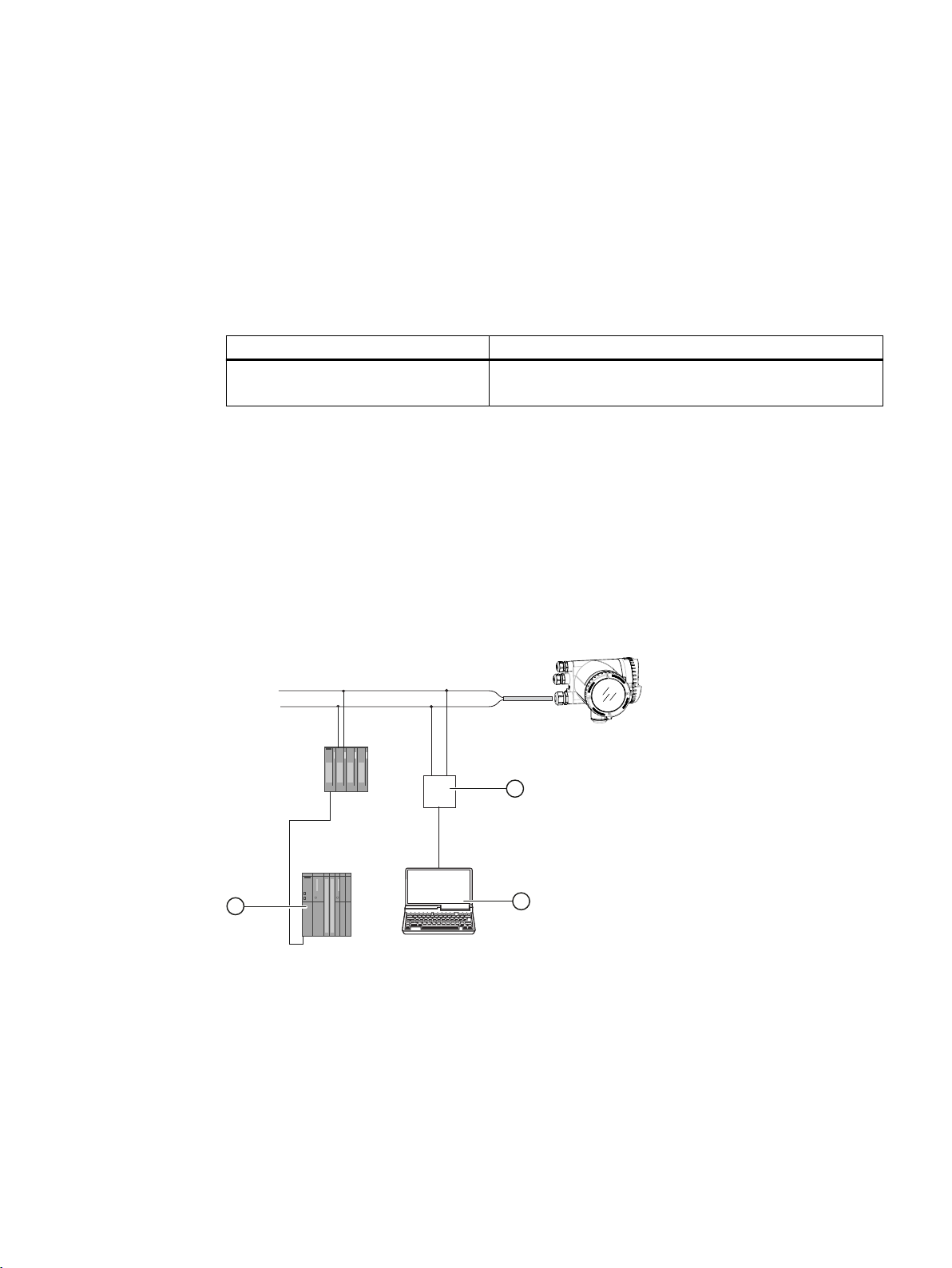
① Communication modem
② PC with SIMATIC PDM or similar application
③ SIMATIC PLC system with HART interface
The Coriolis flowmeter can be used in a number of system configurations:
● as a field mounted transmitter supplied with various optional inputs and outputs
● as part of a system environment, for example SIMATIC S7
SITRANS FC330
Operating Instructions, 01/2019, A5E44030648-AB 21

Description
3.2 Design
3.2 Design
3.2.1 Versions
The flowmeter is available in a compact and a remote version.
● Compact version: The SITRANS FC330 is a single mechanical unit where the transmitter is
directly mounted on the sensor.
Figure 3-1 Compact version
● Remote version: The SITRANS FCS300 sensor unit is remotely connected to a SITRANS
FCT030 transmitter. Directly mounted on the sensor, its Digital Sensor Link (DSL) performs
the signal processing of all measured signals in the sensor. The 4-wire connection between
the transmitter and the sensor provides power and high-integrity digital communication
between the DSL and the transmitter.
Figure 3-2 Remote version - M12 connection
SITRANS FC330
22 Operating Instructions, 01/2019, A5E44030648-AB
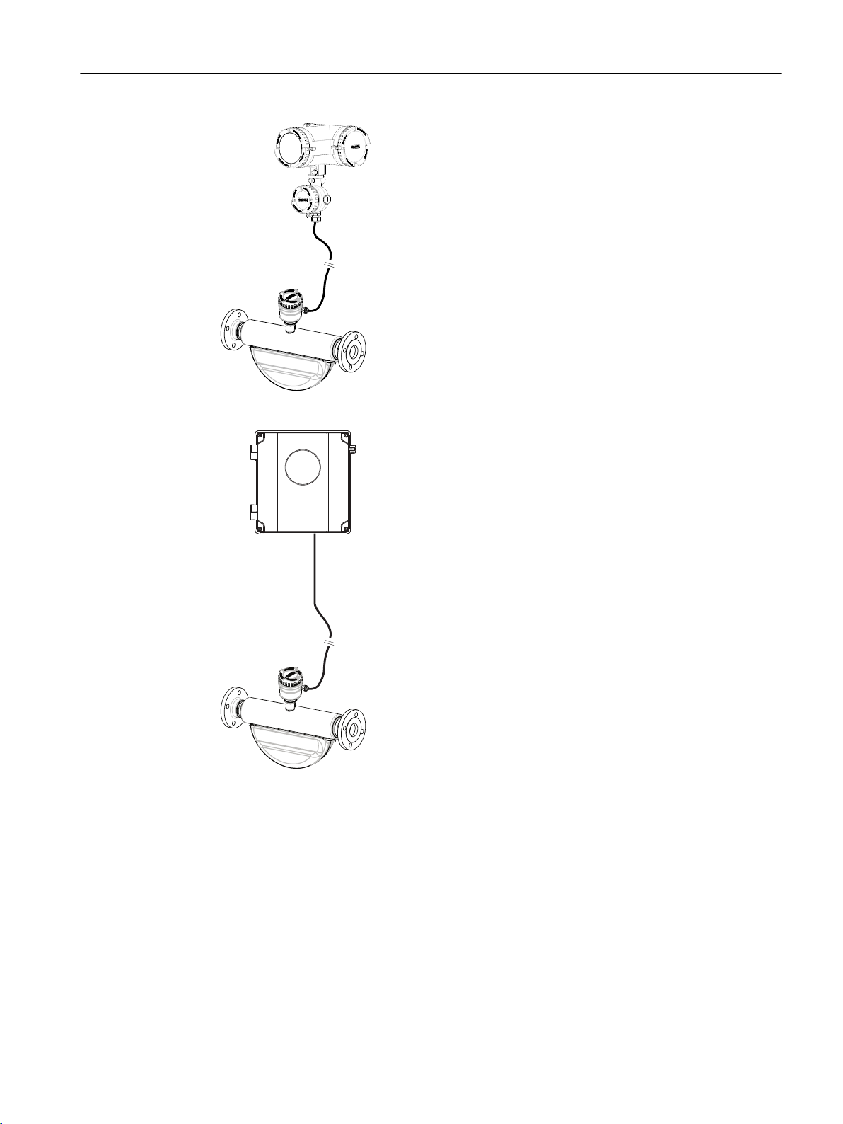
Figure 3-3 Remote version - terminated cable
Description
3.2 Design
Figure 3-4 Remote version with wallmount housing transmitter
3.2.2 Sensor design
All primary process measurements of mass flow, volume flow, density and process
temperature are made in the DSL.
The sensor comprises two parallel bent tubes welded directly to the process connections at
each end via a manifold. The sensor is available in an intrinsically safe (IS) design for
hazardous area installations.
The sensors are available in AISI 316L stainless steel and C4 (2.4610) nickel alloy or C22
(2.4602) nickel alloy. The enclosure is made of Stainless steel 1.4404 (AISI 316L), 1.4301 (AISI
SITRANS FC330
Operating Instructions, 01/2019, A5E44030648-AB 23

Description
3.2 Design
Sensor overview
304), 1.4308 (ASTM CF8). The maximum permissible operating pressure is determined by the
respective process connection, considering the process temperature.
Note
Ex certification requires that the threaded ports always remain closed.
In the remote version, the DSL is available in a painted aluminum with an ingress protection
grade of IP67/NEMA 4X. For communication and supply voltage a 4-wire connection can be
made via M12 plug and socket or cable gland/conduit entry for cable termination.
① DSL (remote version only)
② Lid-lock
③ Cable feed-through (M12 socket or gland)
④ Plug and threaded port for e.g. pressure guard
⑤ Sensor enclosure
⑥ Process connections
Figure 3-5 Overview remote and compact configuration
3.2.3 Transmitter design
The transmitter reads the primary values from the sensor and calculates derived values. It
provides up to four configurable I/Os. On channel 1, HART communication, PROFIBUS DP,
PROFIBUS PA or Modbus RTU RS-485 is possible. On channel 2, 3, 4 each I/O can be
individually configured. A local display (human machine interface - HMI) is available, which
consists of a display and four buttons for user interaction. The transmitter adds functionalities
such as Standard volume flow, fractions, totalizers, dosing, access control, diagnostics,
configuration and logging.
The transmitter has a modular design with discrete, replaceable electronic modules and
connection boards to maintain separation between functions and facilitate field service. All
modules are fully traceable and their provenance is included in the transmitter setup.
SITRANS FC330
24 Operating Instructions, 01/2019, A5E44030648-AB
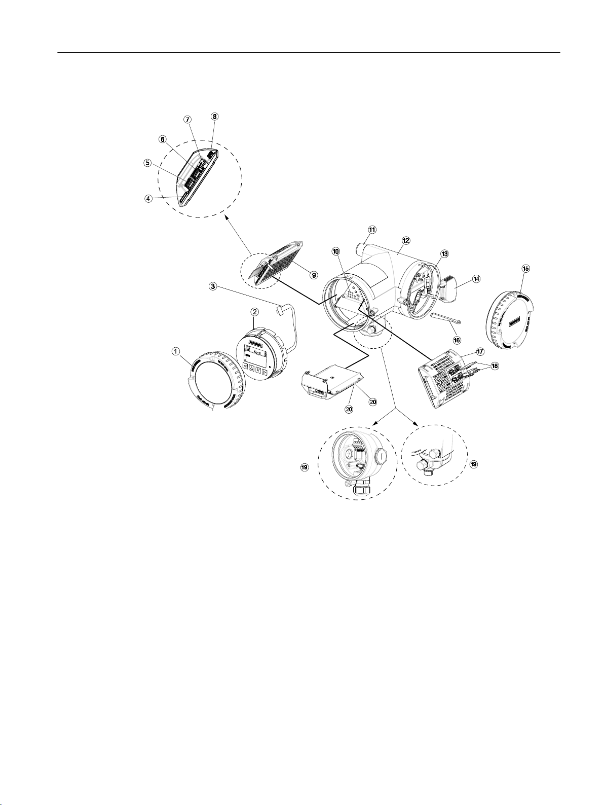
Transmitter exploded view
D
E
D
E
Description
3.2 Design
① Display cover ⑫ Transmitter housing
② Local display (HMI) ⑬ Terminal compartment
③ Connector for HMI ⑭ Power supply terminal protection cover
④ SD card (SensorFlash) ⑮ Lid for terminal compartment
⑤ DIP switch (for custody transfer) ⑯ Wiring tool
⑥ DIP switch (for HART and Modbus) ⑰ I/O cassette (optional)
⑦ HMI port ⑱ I/O configuration keys (optional)
⑧ USB service port ⑲a M12 socket
⑨ Transmitter cassette ⑲b Terminal housing
⑩ Heatsink cover for power supply module ⑳a Sensor module (compact version)
⑪ Cable entry ⑳b Barrier module (remote version)
Figure 3-6 Transmitter exploded view
SITRANS FC330
Operating Instructions, 01/2019, A5E44030648-AB 25
Description
3.2 Design
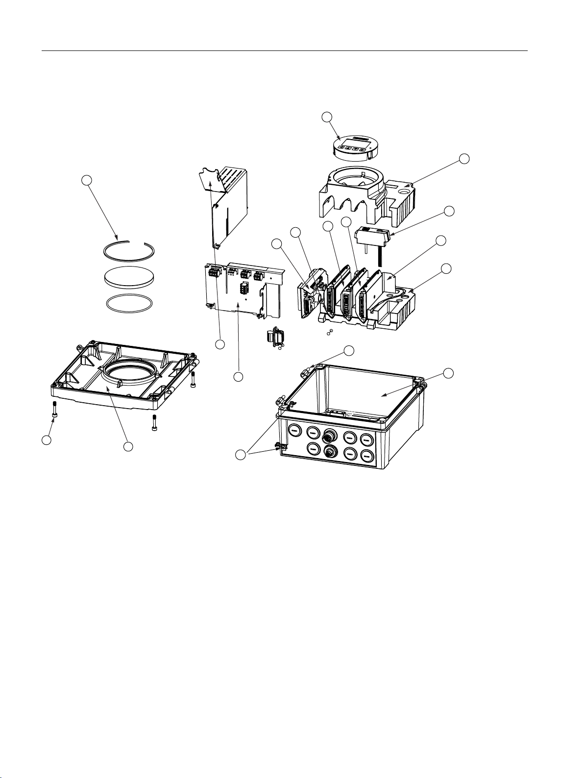
3.2.4 Wall mount housing transmitter exploded view
① Display glass with retaining ring ⑩ Foam bottom
② Power supply module (complete) ⑪ Hinge pin
③ SensorFlash (SD card) ⑫ Housing
④ Transmitter cassette ⑬ Ground connect set
⑤ IO cassette ⑭ Backplane module
⑥ HMI module ⑮ Power supply connector cover
⑦ Foam top ⑯ Front cover enclosure
⑧ Foam plugs ⑰ Front cover mounting screws
⑨ Sensor module (analog version)
Barrier module (digital version)
Figure 3-7 Wall mount housing transmitter exploded view
SITRANS FC330
26 Operating Instructions, 01/2019, A5E44030648-AB
3.3 Device identification
6\VWHPRUGHUQR0(/$*&=
$%()&/
7UDQVPRUGHUQR0(/$1&=
$%()&/
3RZHUVXSSO\9$&WR+]9$RU9'&:
0DWHULDO9HUVLRQ$OXPLQLXP5HPRWH
&RQGXLW&DEOHHQWULHV[0[0[
6HULDOQR1.;;;;;;;
6\VWHPUHYLVLRQV
):+:
<HDURIPDQXIDFWXUH
(QFORVXUH,37\SH;
7DPEr&r)WRr&r)
6,75$16)&7
SIEMENS
6LHPHQV$*'(.DUOVUXKH
0DGHLQ*HUPDQ\DVVHPEOHGLQ)UDQFH
Each part of the FC330 Coriolis flowmeter has 3 nameplate types which show the following
information:
● product identification
● product specifications
● certificates and approvals
Note
Identification
Identify your device by comparing your ordering data with the information on the product and
specification nameplates.
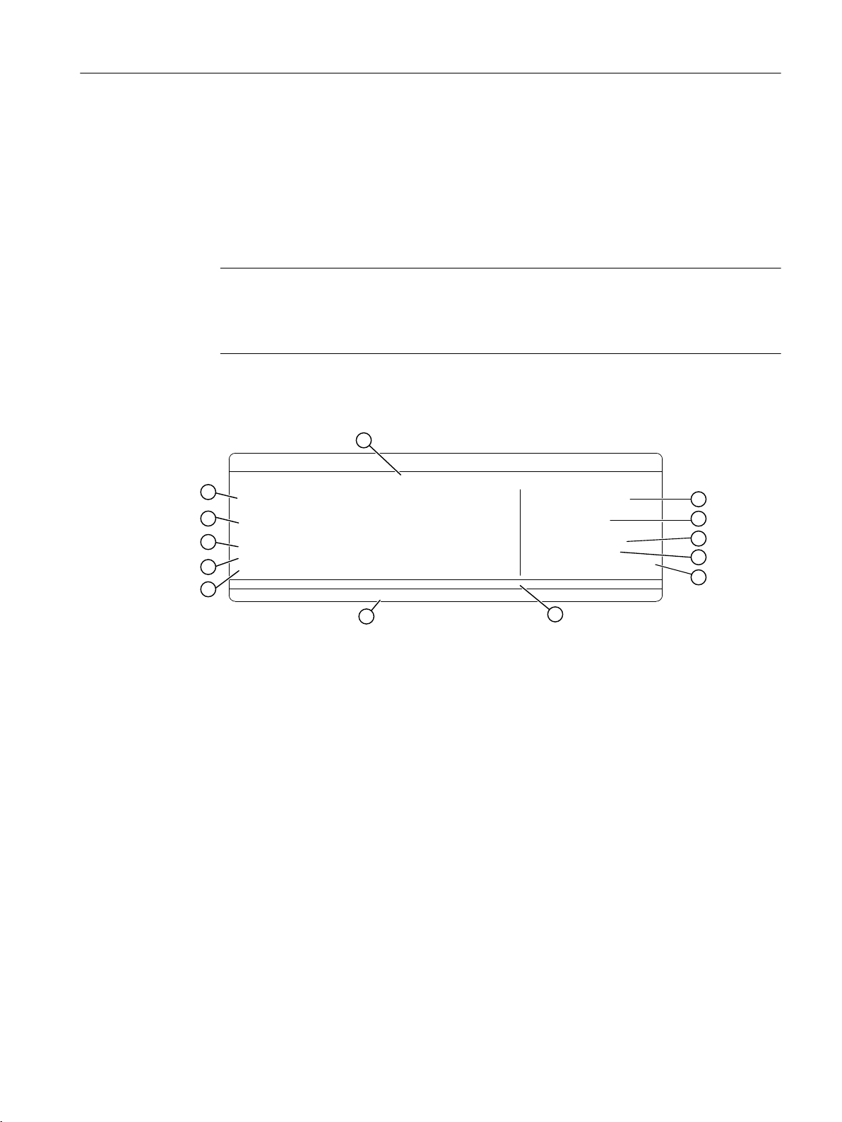
Transmitter identification nameplate example
Description
3.3 Device identification
① SITRANS FCT030
② Serial no. Serial number
③ System revisions System revision numbers firmware (FW) and hardware (HW)
④ Year of manufacture Manufacturing year
⑤ Enclosure Degree of protection
⑥ Tamb. Range of ambient temperature
⑦ Manufacturer Manufacturer name and location
⑧ Country Manufacturing country
⑨ Conduit / Cable entries Type of conduit / cable entries
⑩ Material / Version Transmitter housing material and version (compact/remote)
⑪ Power supply Power supply
⑫ Transm. order no. Device-specific transmitter order number
⑬ System order no. Device-specific system order number (transmitter and sensor)
1)
With compact versions, the transmitter and sensor product identifications are both given as 'SITRANS
SITRANS FC330
Operating Instructions, 01/2019, A5E44030648-AB 27
FC330'.
With remote versions, the transmitter is identified as 'SITRANS FCT030' and the sensor as 'SITRANS
FCS300'.
1)
Product name

6LHPHQV$*'(.DUOVUXKH
0DGHLQ*HUPDQ\DVVHPEOHGLQ)UDQFH
SIEMENS
6HULDOQR1.;;;;;;;
6HQ56
6L]H'1
6\VWHPRUGHUQR0(/$*&=
$%()&/
6HQVRURUGHUQR0(/$1&=
$%()&/
6,75$16)&6
Description
3.3 Device identification
Sensor identification nameplate example
① SITRANS
FCS300
1)
② Serial no. Serial number
③ Sen. RS Mechanical sensor version number
④ Size DN Size
⑤ Manufacturer Manufacturer name and location
⑥ Country Manufacturing country
⑦ Sensor order no. Sensor replacement order number
⑧ System order no. Flowmeter system order number (transmitter and sensor)
1)
With compact versions, the transmitter and sensor product identifications are both given as 'SITRANS
FC330'.
With remote versions, the transmitter is identified as 'SITRANS FCT030' and the sensor as 'SITRANS
FCS300'.
Flowmeter serial number construction
The flowmeter serial number consists of the following:
PPYMDDXXXX
where
PP = Production factory (Siemens Flow Instruments: N1)
Y = Production year (for encryption, see below)
M = Production month (for encryption, see below)
DD = Production day (for encryption, see below)
XXXX = Sequential number
Product name
28 Operating Instructions, 01/2019, A5E44030648-AB
Encryption:
Calendar year (Y) Code
1950, 1970, 1990, 2010 A
1951, 1971, 1991, 2011 B
1952, 1972, 1992, 2012 C
1953, 1973, 1993, 2013 D
1954, 1974, 1994, 2014 E
1955, 1975, 1995, 2015 F
1956, 1976, 1996, 2016 H (G)
1957, 1977, 1997, 2017 J
SITRANS FC330

Description
3.3 Device identification
1958, 1978, 1998, 2018 K
1959, 1979, 1999, 2019 L
1960, 1980, 2000, 2020 M
1961, 1981, 2001, 2021 N
1962, 1982, 2002, 2022 P
1963, 1983, 2003, 2023 R
1964, 1984, 2004, 2024 S
1965, 1985, 2005, 2025 T
1966, 1986, 2006, 2026 U
1967, 1987, 2007, 2027 V
1968, 1988, 2008, 2028 W
1969, 1989, 2009, 2029 X
Month (M) Code
January 1
February 2
March 3
April 4
May 5
June 6
July 7
August 8
September 9
October O
November N
December D
Day (DD) Code
Day 01 to 31 01 to 31 (corresponding to the actual date)
SITRANS FC330
Operating Instructions, 01/2019, A5E44030648-AB 29
4
5
2 31
)RU&DQ
([GEHELD>LD*D@,,&,,%77*E
)RU86
&O,'LY*URXSV$%&'
&ODVV,=RQH
$([GEHELD>LD*D@,,&,,%77*E
([LD
(;GEHELD>LD*D@,,&7*D*E
6LUD$7(;;
,(&([6,5;
7D r&WRr&
7&ODVV XSSHU7DPE
5HIHUWRXVHULQVWUXFWLRQV
,,*
Description
3.3 Device identification
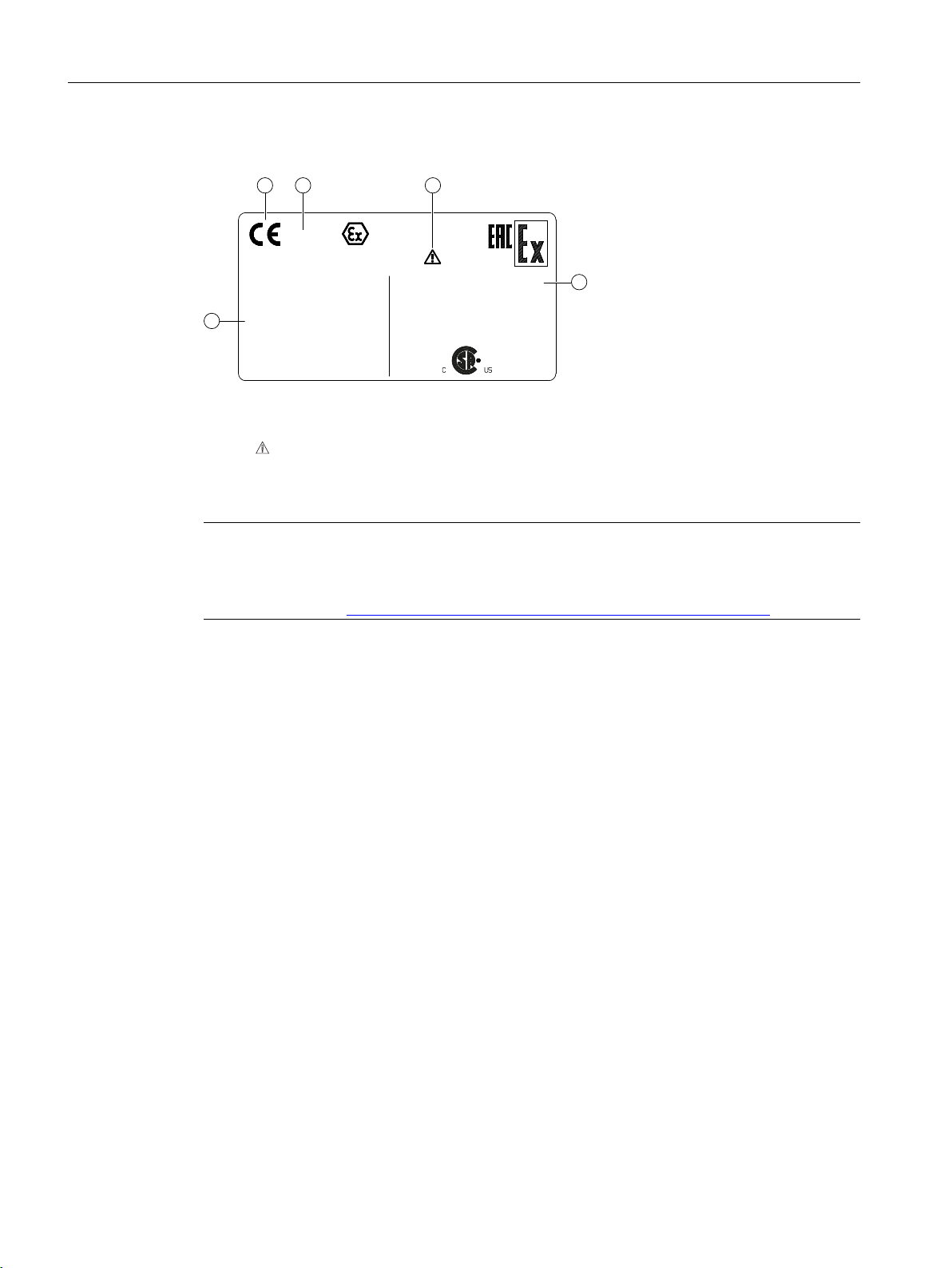
FCT030 transmitter specification nameplate example
① CE CE mark
② 0518 Notified Body ID (ATEX example)
③ Consult the operating instructions
④ For Can / For US Country-specific restrictions
⑤ Ex approvals Classification for hazardous locations
Note
Approvals and identifications
Approval certificates and notified body identifications are available for download at
www.siemens.com (http://www.siemens.com/processinstrumentation/certificates).
30 Operating Instructions, 01/2019, A5E44030648-AB
SITRANS FC330
 Loading...