

Siemens SITRANS 7MF1570 Operating Instructions Manual

s
SITRANS P, MPS series
7MF1570
Edition 05/2006
Druckmessumformer für Füllstandmessung
Betriebsanleitung ..............................................................................................Seite 3
Pressure Transmitter for Level Measurement
Operating Instructions.......................................................................................Page 15
Transmetteur de pression pour mesure de niveau
Instructions de service ......................................................................................Page 27
Transmisor de presión para la medición de los niveles
Instrucciones de servicio...................................................................................Página 39
Transmettitore di pressione per la misurazione del livello
Istruzioni de servizio .........................................................................................Pagina 51
Transdutor de pressão para medição do nível
Manual de instruções........................................................................................Página 63
Certificates........................................................................................................Page 75
SITRANS P, MPS series
A5E00136035-04
1

SITRANS P, MPS series
2 A5E00136035-04

Inhaltsverzeichnis
1 Aufbau . . . . . . . . . . . . . . . . . . . . . . . . . . . . . . . . . . . . . . . . . . . . . . . . . . .7
2 Anwendungsbereich . . . . . . . . . . . . . . . . . . . . . . . . . . . . . . . . . . . . . . .7
3 Arbeitsweise . . . . . . . . . . . . . . . . . . . . . . . . . . . . . . . . . . . . . . . . . . . . . 8
4 Installation . . . . . . . . . . . . . . . . . . . . . . . . . . . . . . . . . . . . . . . . . . . . . . . .8
5 Verbindungsleitungen . . . . . . . . . . . . . . . . . . . . . . . . . . . . . . . . . . . . . .9
6 Kalibrierung . . . . . . . . . . . . . . . . . . . . . . . . . . . . . . . . . . . . . . . . . . . . .10
7 Wartung . . . . . . . . . . . . . . . . . . . . . . . . . . . . . . . . . . . . . . . . . . . . . . . . .10
8 Bestelldaten . . . . . . . . . . . . . . . . . . . . . . . . . . . . . . . . . . . . . . . . . . . . .10
9 Technische Daten . . . . . . . . . . . . . . . . . . . . . . . . . . . . . . . . . . . . . . . . .11
10 Optionen/Ersatzteile . . . . . . . . . . . . . . . . . . . . . . . . . . . . . . . . . . . . . . 12
10.1 Kabeldose 7MF1570-8AA . . . . . . . . . . . . . . . . . . . . . . . . . . . . . . . . . . .12
10.2 Abspannklemme 7MF1570-8AB . . . . . . . . . . . . . . . . . . . . . . . . . . . . . . .13
10.3 Messstellenaufbau . . . . . . . . . . . . . . . . . . . . . . . . . . . . . . . . . . . . . . . . .14
11 Zertifikate und Zulassungen . . . . . . . . . . . . . . . . . . . . . . . . . . . . . . . .75
SITRANS P, Serie MPS
A5E00136035-04
3
Sicherheitstechnische Hinweise
Dies Anleitung enthält Hinweise, die Sie zu Ihrer persönlichen Sicherheit sowie zur Vermeidung von Sachschäden beachten müssen. Die Hinweise sind durch ein Warndreieck hervorgehoben und je nach Gefährdungsgrad folgendermaßen dargestellt.
GEFAHR
bedeutet, dass Tod, schwere Körperverletzung oder erheblicher Sachschaden eintreten werden, wenn die entsprechenden Vorsichtsmaßnahmen nicht getroffen
werden.
WARNUNG
bedeutet, dass Tod, schwere Körperverletzung oder erheblicher Sachschaden eintreten können, wenn die entsprechenden Vorsichtsmaßnahmen nicht getroffen
werden.
VORSICHT
mit Warndreieck bedeutet, dass eine leichte Körperverletzung eintreten kann,
wenn die entsprechenden Vorsichtsmassnahmen nicht getroffen werden.
VORSICHT
ohne Warndreieck bedeutet, dass ein Sachschaden eintreten kann, wenn die
entsprechenden Vorsichtsmaßnahmen nicht getroffen werden.
ACHTUNG
bedeutet, dass ein unerwünschtes Ergebnis oder Zustand eintreten kann, wenn
der entsprechenden Hinweis nicht beachtet wird.
HINWEIS
Bedeutet einen Hinweis auf einen möglichen Vorteil, wenn die Empfehlung
Copyright © Siemens AG 2001 All rights reserved
Weitergabe sowie Vervielfältigung dieser Anleitung,
Verwertung und Mitteilung ihres Inhalts ist nicht gestat
tet, soweit nicht ausdrücklich zugestanden. Zuwiderhandlungen verpflichten zu Schadenersatz. Alle Rechte
vorbehalten, insbesondere für den Fall der Patentertei
lung oder GM-Eintragung
Siemens AG
Bereich Automatisierungs- und Antriebstechnik
Geschäftsgebiet Process Instrumentation
D-76181 Karlsruhe
eingehalten wird.
-
-
Haftungsausschluss
Wir haben den Inhalt der Anleitung auf Übereinstimmung mit
der beschriebenen Hard-und Software geprüft. Dennoch
können Abweichungen nicht ausgeschlossen werden, so
dass wir für die vollständige Übereinstimmung keine Gewähr
übernehmen. Die Angaben in dieser Anleitung werden
regelmäßig überprüft, und notwendige Korrekturen sind in
den nachfolgenden Auflagen enthalten. Für
Verbesserungsvorschläge sind wir dankbar.
© Siemens AG 2001
Technische Änderungen bleiben vorbehalten
SITRANS P, Serie MPS
4 A5E00136035-04

Allgemeine Hinweise
HINWEIS
Sehr geehrter Kunde,
die Anleitung enthält aus Gründen der Übersichtlichkeit nicht sämtliche Detailinfor-
mationen zu allen Typen des Produkts und kann auch nicht jeden denkbaren Fall
der Aufstellung, des Betriebes oder der Instandhaltung berücksichtigen.
Sollten Sie weitere Informationen wünschen, oder sollten besondere Probleme
auftreten, die in der Anleitung nicht ausführlich genug behandelt werden, können
Sie die erforderliche Auskunft über die örtliche Siemens-Niederlassung anfordern.
Außerdem weisen wir darauf hin, dass der Inhalt der Anleitung nicht Teil einer früheren oder bestehenden Vereinbarung, Zusage oder eines Rechtverhältnisses ist
oder diese abändern soll. Sämtliche Verpflichtungen der Siemens AG ergeben
sich aus dem jeweiligen Kaufvertrag, der auch die vollständige und allein gültige
Gewährleistungsregelung enthält. Diese vertraglichen Gewährleistungsbestim
mungen werden durch die Ausführungen der Anleitung weder erweitert noch
beschränkt.
Der Inhalt spiegelt den technischen Stand zur Drucklegung wieder. Technische
Änderungen sind im Zuge der Weiterentwicklung vorbehalten.
WARNUNG
Geräte der Zündschutzart "Eigensicherheit" verlieren ihre Zulassung, sobald sie
an Stromkreisen betrieben wurden, die nicht der in Ihrem Land gültigen Prüfbe
scheinigung entsprechen.
Das Gerät kann mit hohem Druck sowie aggressiven Medien betrieben werden.
Deshalb sind bei unsachgemäßem Umgang mit diesem Gerät schwere Körperver
letzungen und/oder erheblicher Sachschaden nicht auszuschließen.
Der einwandfreie und sichere Betrieb dieses Gerätes setzt sachgemäßen Transport, fachgerechte Lagerung, Aufstellung und Montage sowie sorgfältige Bedienung und Instandhaltung voraus.
Das Gerät darf nur zu den in dieser Betriebsanleitung vorgegebenen Zwecken eingesetzt werden.
-
-
-
Haftungsausschluss
Sämtliche Änderungen am Gerät, sofern sie nicht in der Anleitung ausdrücklich erwähnt werden, fallen in die Verantwortung des Anwenders.
SITRANS P, Serie MPS
A5E00136035-04
5

Qualifiziertes Personal
sind Personen, die mit Aufstellung, Montage, Inbetriebsetzung und Betrieb des Produktes vertraut sind und über die ihrer Tätigkeit entsprechenden Qualifikationen verfügen, wie z. B.:
• Ausbildung oder Unterweisung bzw. Berechtigung, Geräte/Systeme gemäß des
Standards der Sicherheitstechnik für elektrische Stromkreise, hohe Drücke und
aggressive sowie gefährliche Medien zu betreiben und zu warten.
• Bei Geräten mit Explosionsschutz: Ausbildung oder Unterweisung bzw. Berech-
tigung, Arbeiten an elektrischen Stromkreisen für explosionsgefährdete Anlagen
durchzuführen.
• Ausbildung oder Unterweisung gemäß des Standards der Sicherheitstechnik in
Pflege und Gebrauch angemessener Sicherheitsausrüstung.
VORSICHT
Elektrostatisch gefährdete Baugruppen können durch Spannungen zerstört werden, die weit unterhalb der Wahrnehmungsgrenze des Menschen liegen. Diese
Spannungen treten bereits auf, wenn Sie ein Bauelement oder elektrische
Anschlüsse einer Baugruppe berühren, ohne elektrostatisch entladen zu sein. Der
Schaden, der an einer Baugruppe aufgrund einer Überspannung eintritt, kann
meist nicht sofort erkannt werden, sondern macht sich erst nach längerer Betriebs
zeit bemerkbar.
-
Marken
SIMATIC®, SIPART®, SIREC®, SITRANS® sind eingetragene Marken der Siemens
AG.
Die übrigen Bezeichnungen in dieser Anleitung können Marken sein, deren Benutzung durch Dritte für deren Zwecke die Rechte der Inhaber verletzen können.
SITRANS P, Serie MPS
6 A5E00136035-04
1 Aufbau
Der Messumformer hat einen frontbündig eingebauten Piezowiderstands-Sensor mit
Messemembrane aus Edelstahl.
Der Messumformer ist mit einer Elektronik ausgerüstet, die zusammen mit dem Sensor in ein Gehäuse aus Edelstahl eingebaut ist. Im Anschlusskabel befinden sich außerdem ein Tragseil und ein Entlüftungsrohr.
Die Messmembran wird durch eine Schutzkappe vor äußeren Einflüssen wirksam
geschützt.
Der Sensor, die Elektronik und das Anschlusskabel sind in einem hermetisch gekapselten Gehäuse mit kleinen Abmessungen untergebracht.
Der Messumformer ist für einen weiten Temperaturbereich kompensiert.
2 Anwendungsbereich
Der Messumformer 7MF1570 wird für die hydrostatische Füllstandmessung eingesetzt, z. B. in der Wasserversorgung, bei Schiffsinstallationen, in der Öl- und Gasindustrie usw. Der Messumformer dient zur Messung des hydrostatischen Drucks
(p = ρ * g * h, mit: ρ - Dichte der Flüssigkeit, g - Erdbeschleunigung, h – Höhe der
Flüssigkeitssäule).
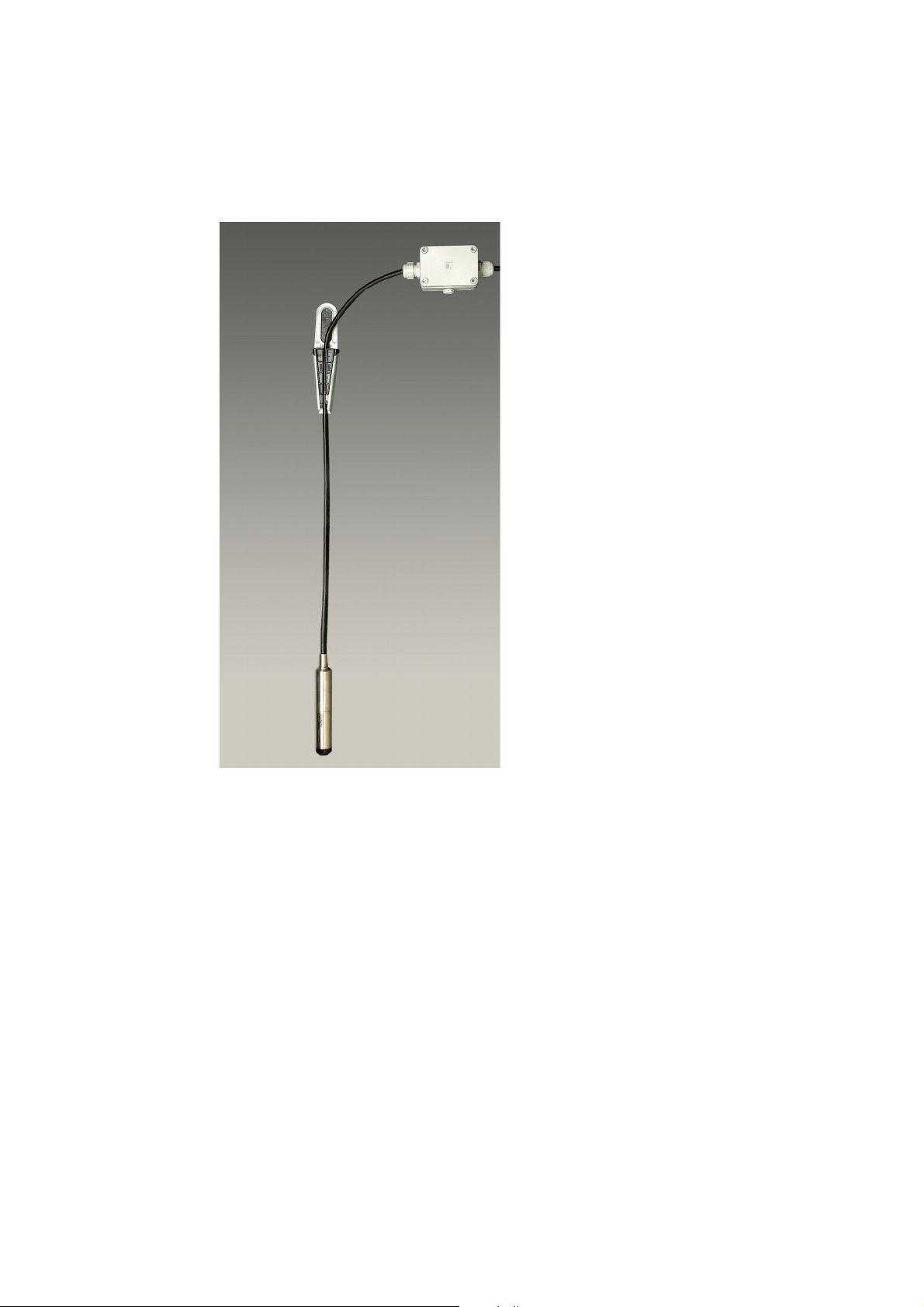
Betriebsanleitung
Bild 1 Messumformer 7MF1570, Füllstandmessung in offenen Behältern
Die chemische Beständigkeit von Sensor, Gehäuse, O-Ring und Anschlusskabel gegenüber dem Messstoff ist zu beachten.
SITRANS P, Serie MPS
A5E00136035-04
7

Betriebsanleitung
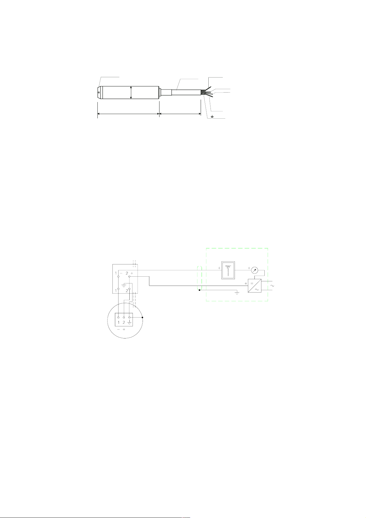
3 Arbeitsweise
Der Druck des Mediums wirkt auf die Membrane aus nichtrostendem Stahl, welche
ausgelenkt wird und so den Druck an die Piezo-Widerstandsbrücke in dem Messsen
sor überträgt. Jeder Sensor ist für Temperaturänderungen kompensiert und arbeitet
in einem breiten Temperaturbereich.
Das Ausgangs-Spannungssignal des Sensors wird einer Elektronik zugeführt, die es
in einen Ausgangsstrom im Bereich von 4 bis 20 mA umwandelt. Auf die Membrane
des Sensors wirkt der hydrostatische Druck, welcher mit der Eintauchtiefe proportio
nal ist. Dieser Druck wird mit dem Atmosphärendruck verglichen, welcher, mittels
des Entlüftungsrohrs im Anschlusskabel, auf die andere Seite des Sensors wirkt. Der
Kabelschirm ist an das Gehäuse angeschlossen.
Sensor
Membrane
p
U
const.
-
-
U
EM
I
+2 (braun)
-1 (blau)
I
, U
o
B
Bild 2 Messumformer 7MF1570, Blockschema
Der Messumformer wird aus einer Gleichstromquelle 10 bis 36 V DC gespeist.
Schutzdioden am Eingang schützen gegen falsche Polarität oder zu hohe Span
nung. Der Messumformer erfüllt die Richtlinien DIN EN 61 326 und NAMUR NE 21
hinsichtlich elektromagnetischer Verträglichkeit (EMV).
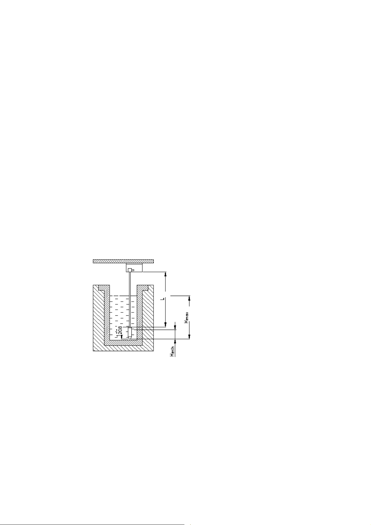
4 Installation
Der Messumformer 7MF1570 wird am Kabel nach unten hängend eingebaut. Bei bewegten Medien muss der Messumformer befestigt werden, um Messfehler zu verhindern. Dies kann durch ein Führungsrohr oder ein zusätzliches Gewicht am
Messumformer (max. Zugkraft am Tragseil des Anschlusskabels 300 N) erfolgen.
Generell ist das Kabel über den Behälter mit der mitgelieferten Abspannklemme
7MF1570-8AB zu befestigen und das Kabel selbst mit der ebenfalls mitgelieferten
Kabeldose 7MF1570-8AA anzuschließen. Die Kabeldose ist an einem ihrer Schutz
art entsprechenden Ort (IP66) in der Nähe der Messstelle zu montieren.
Es ist darauf zu achten, dass die Eintrittsöffnungen an der Schutzkappe des
Messumformers nicht verschmutzen, um die einwandfreie Funktion zu
gewährleisten.
Entlüftungsrohr
Schirm
-
-
8
HINWEIS
Das Medium darf nicht einfrieren.
SITRANS P, Serie MPS
A5E00136035-04
Betriebsanleitung
Schutzkappe
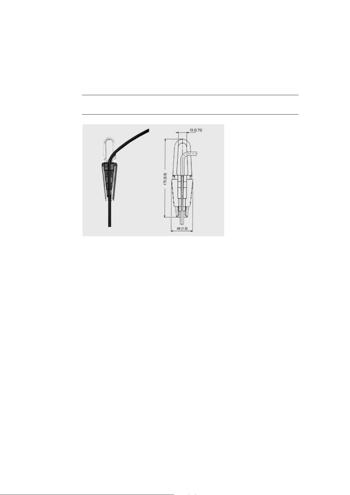
Ø 27
158 L
Mantel 8,3 mm Durchmesser (schwarz, HFFR)
Flexible Leitung mit 0,5 mm
Entlüftungsrohr 1 mm Durchmesser (innerer Durchmesser)
Schutzkappe mit 4 x 3 mm Durchmesser Bohrung (schwarz, PA)
Mantel
Bild 3 Messumformer 7MF1570, Maße
5 Verbindungsleitungen
Der Messumformer 7MF1570 für die Füllstandmessung (Schutzart IP68 nach DIN
EN 60 529) ist an die Kabeldose 7MF1570-8AA (IP54) angeschlossen. Das Kabel
des Messumformers wird an die Klemmen 1(-), 2(+) und an die Erdung (
geschlossen werden. Das Tragseil wird in dem Befestigungsteil zwischen den zwei
Schrauben geklemmt. Das Entlüftungsrohr muss in Verbindung mit der Atmosphäre
innerhalb der Dose stehen.
+ (braun)
2
Querschnitt
Entlüftungsrohr
Tragseil (weiß)
- (blau)
Schirm
Bild 4) an-
Atmosphärendruck
Kabeldose
Entlüftungsrohr
P70
Bild 4 Messumformer 7MF1570, Anschlussschema
Die Speisespannung des Messumformers darf in einem Bereich von 10 bis 36 V DC
liegen. Der Widerstandswert für die grösste Belastung hängt von der Spannung U
B
ab. Er wird nach folgender Gleichung ermittelt:
UB - 10 V
R
= ————— (kOhm)
max
20 mA
SITRANS P, Serie MPS
A5E00136035-04
9

Betriebsanleitung
6 Kalibrierung
Der Messumformer wurde im Herstellerwerk auf den Messbereich kalibriert und kann
nicht nachkalibriert werden.
7Wartung
Für den Messumformer ist keine Wartung erforderlich.
Bei der Anwendung des Geräts ist folgendes besonders zu beachten:
• Der grösste zugelassene Druck p
des Messumformers darf nicht überschrit-
max
ten werden.
• Die Temperatur des Mediums im Kontakt mit dem Messumformer darf 80C nicht
überschreiten.
• Eisbildung an dem Prozesseingang des Gebers vermeiden, weil dadurch die
Messmembrane beschädigt werden kann.
• Die Verschmutzung des Sensoreneingangs verhindern.
• Die Behinderung des Entlüftungsrohres in dem Sonderkabel vermeiden (Einfluss
auf die Messgenauigkeit).
8 Bestelldaten
Messumformer SITRANS P
für Druck, Serie MPS (Brunnensonde)
Zweileitertechnik
Hinweis: Kabeldose und Abspannklemme sind im Lieferumfang
enthalten.
Messbereich Kabellänge L
0 bis 2 mH2O 10 m
0 bis 4 mH2O 10 m
0 bis 6 mH2O 25 m
0 bis 10 mH2O 25 m
0 bis 20 mH2O 25 m
0 bis 6 ftH2O 32 ft
0 bis 12 ftH2O 32 ft
0 bis 18 ftH2O 82 ft
0 bis 30 ftH2O 82 ft
0 bis 60 ftH2O 82 ft
Sondermessbereich/Sonderkabellänge1) (Messbereich und Kabel-
länge im Klartext angeben)
Explosionsschutz
• ohne Explosionsschutz
• mit Explosionsschutz Schutzart "Eigensicherheit" EEx ia IIC T4
Zubehör (als Ersatzteil)
Kabeldose 7MF1570-8AA
für den Anschluss des Messumformerkabels
Abspannklemme 7MF1570-8AB
zur Befestigung des Messumformers
1)
Es sind Sondermessbereich zwischen 0 ... 1 mH2O (0 ... 3 ftH2O) und 0 ... 100 mH2O (0 ... 200 ftH2O) und Sonderkabellängen bis 200 m (600 ft)
möglich. Bei Ex-Ausführungen ist eine max. Sonderkabellänge von 50 m (150 ft) möglich.
7MF1570-1 A0
C
D
E
F
G
K
L
M
N
P
X
1
2
10
SITRANS P, Serie MPS
A5E00136035-04

Betriebsanleitung
9 Technische Daten
Eingang
Messgröße Druck
Messbereich Überlastgrenze
• 0 bis 2 mH2O
•0 bis 4 mH2O
•0 bis 6 mH2O
• 0 bis 10 mH2O
• 0 bis 20 mH2O
Ausgang
Ausgangssignal 4 bis 20 mA
Messgenauigkeit
Messabweichung (einschließlich Nichtlinearität, Hysterese
und Wiederholbarkeit, bei 25 °C (77 °F))
Einfluss der Umgebungstemperatur
• Nullpunkt und Spanne
- zwischen 1 und 6 mH2O (zwischen 3 und 18 ftH2O)
- ≥ 6 mH
Langzeitstabilität
• Nullpunkt und Spanne
- zwischen 1 und 6 mH2O (zwischen 3 und 18 ftH2O)
- ≥ 6 mH
Vibrationseffekt (10 bis 500 Hz in jeder Achsenrichtung) 0,05 %/g vom Messbereichsendwert
Einfluss der Hilfsenergie 0,01 %/V vom Messbereichsendwert
Einsatzbedingungen
Umgebungsbedingungen
• Arbeitstemperatur
• Lagerungstemperatur
Schutzart nach DIN EN 60 529 IP68
Elektromagnetische Verträglichkeit
• Störfestigkeit
Konstruktiver Aufbau
Gewicht
• Messumformer
• Kabel
Elektrischer Anschluss Kabel mit 2 Leitern mit Schirm und Entlüftungsrohr, Trag-
Werkstoff
• Sensor
• Gehäuse
•O-Ring
• Anschlusskabel
Hilfsenergie
Klemmenspannung am Messumformer U
Verpolungsschutz ja
Überspannungsschutz ja
Bürde RB = (UB - 10 V) / 0,02 A in Ω
Zertifikate und Zulassungen
Das Gerät unterliegt nicht der Druckgeräterichtlinie 97/23/EC
Explosionsschutz
• Eigensichere Ausführung
- Eigensicherheit "i" TÜV 03 ATEX 2004X
- Kennzeichnung II 1G EEx ia IIC Tv
- Zul. Umgebungstemperatur -10 bis +80 °C (14 bis 176 °F)
- Anschluss an bescheinigte eigensichere Stromkreise
- Wirksame innere Induktivität und Kapazität in
O (≥ 18 ftH2O)
2
O (≥ 18 ftH2O)
2
B
mit den Höchstwerten:
Abhängigkeit der Länge des Anschlusskabels
1,4 bar (20.3 psi) (= 14 mH2O/42 ftH2O)
1,4 bar (20.3 psi) (= 14 mH2O/42 ftH2O)
3,0 bar (43.5 psi) (= 30 mH
3,0 bar (43.5 psi) (= 30 mH
6,0 bar (87.0 psi) (= 60 mH
0,2 % vom Messbereichsendwert
0,45 %/10 K (0,45 %/18 °F) vom Messbereichsendwert
0,3 %/10 K (0,3 %/18 °F) vom Messbereichsendwert
0,25 % vom Messbereichsendwert/Jahr
0,2 % vom Messbereichsendwert/Jahr
-10 bis +80 °C (+14 bis +176 °F)
-40 bis +100 °C (-40 bis +212 °F)
nach DIN EN 61 326, NAMUR NE 21
0,4 kg (0.88 lb)
0,08 kg/m (0.054 lb/ft)
seil (max. 300 N (67.7 lbf))
Edelstahl, W.-Nr. 1.4571/316Ti
Edelstahl, W.-Nr. 1.4571/316Ti
Viton
PE/HFFR-Mantel (nicht-halogen)
DC 10 bis 36 V
Ui = 30 V, li = 100 mA, Pi = 750 mW
Li = 165 µH + 1,5 µH/m, Ci = 38,3 nF + 0,25 nF/m
O/90 ftH2O)
2
O/90 ftH2O)
2
O/180 ftH2O)
2
SITRANS P, Serie MPS
A5E00136035-04
11
Betriebsanleitung
10 Optionen/Ersatzteile
10.1 Kabeldose 7MF1570-8AA
Anwendungsbereich für den Anschluss des Messumformerkabels
Konstruktiver Aufbau
Gewicht 0,2 kg (0.44 lb)
Elektrischer Anschluss 2 x 3-fach (28 bis 18 AWG)
Kabeleinführung 2 x Pg 13,5
Gehäusewerkstoff Polycarbonat
Entlüftungsrohr für atmosphärischen Druck
Schraube für Tragseil
Einsatzbedingungen
Schutzart nach DIN EN 60 529 IP66
(1) Befestigungsbohrung
(2) Entlüftungsventil
Bild 5 Kabeldose, Maße in mm (inch)
(1)
(1)
(2)
(2)
(3)
12
1) Zur Messwertverarbeitung
(2) Entlüftungsrohr
(3) Zum Messumformer 7MF1570
Bild 6 Kabeldose, geöffnet
SITRANS P, Serie MPS
A5E00136035-04
10.2 Abspannklemme 7MF1570-8AB
Anwendungsbereich zur Befestigung des Messumformers
Konstruktiver Aufbau
Gewicht 0,16 kg (0.35 lb)
Werkstoff Stahl verzinkt, Polyamid
Betriebsanleitung
Bild 7 Abspannklemme, Maße in mm (inch)
SITRANS P, Serie MPS
A5E00136035-04
13
Betriebsanleitung
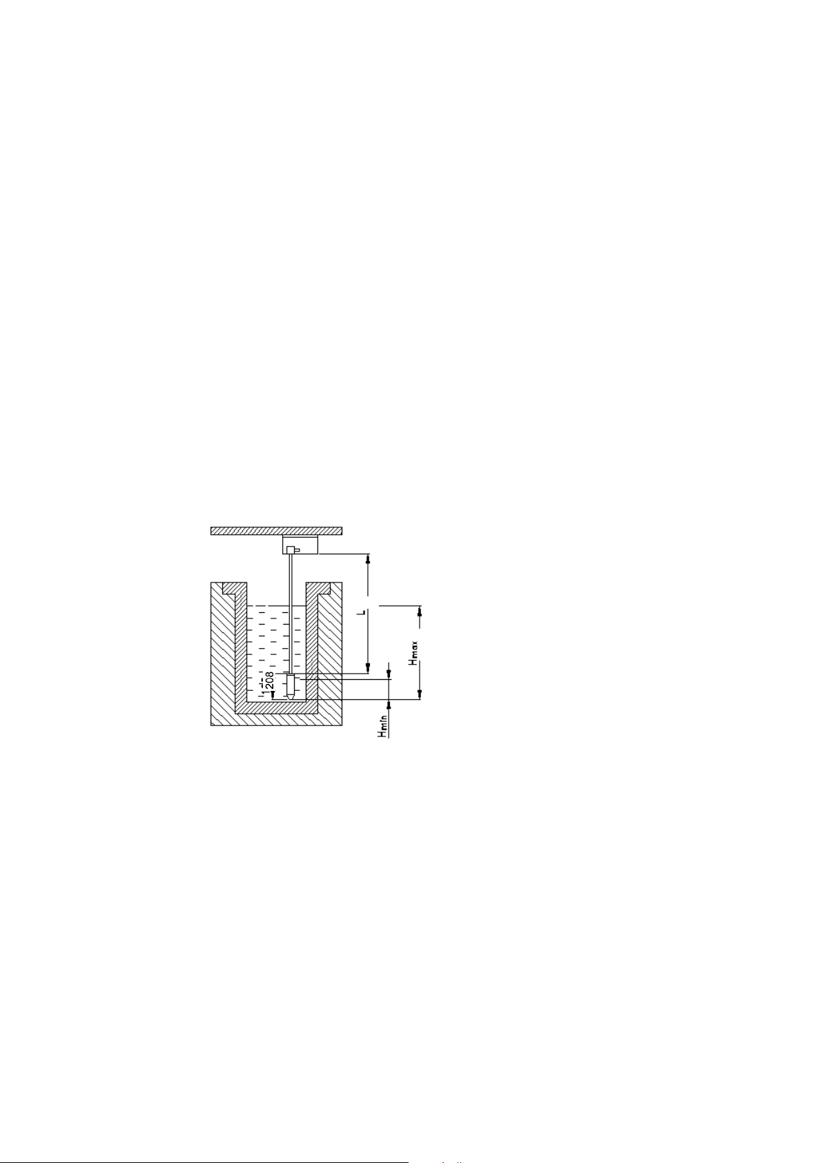
10.3 Messstellenaufbau
14
Bild 8 Messstellenaufbau prinzipiell
SITRANS P, Serie MPS
A5E00136035-04

Contents
1 Design . . . . . . . . . . . . . . . . . . . . . . . . . . . . . . . . . . . . . . . . . . . . . . . . . .19
2 Application . . . . . . . . . . . . . . . . . . . . . . . . . . . . . . . . . . . . . . . . . . . . . .19
3 Mode of operation . . . . . . . . . . . . . . . . . . . . . . . . . . . . . . . . . . . . . . . .20
4 Installation . . . . . . . . . . . . . . . . . . . . . . . . . . . . . . . . . . . . . . . . . . . . . . .20
5 Connecting cables . . . . . . . . . . . . . . . . . . . . . . . . . . . . . . . . . . . . . . . .21
6 Calibration . . . . . . . . . . . . . . . . . . . . . . . . . . . . . . . . . . . . . . . . . . . . . . .22
7 Maintenance . . . . . . . . . . . . . . . . . . . . . . . . . . . . . . . . . . . . . . . . . . . . .22
8 Ordering data . . . . . . . . . . . . . . . . . . . . . . . . . . . . . . . . . . . . . . . . . . . .22
9 Technical data . . . . . . . . . . . . . . . . . . . . . . . . . . . . . . . . . . . . . . . . . . . .23
10 Options / Spare parts . . . . . . . . . . . . . . . . . . . . . . . . . . . . . . . . . . . . . .24
10.1 Junction box . . . . . . . . . . . . . . . . . . . . . . . . . . . . . . . . . . . . . . . . . . . . . .24
10.2 Cable hanger . . . . . . . . . . . . . . . . . . . . . . . . . . . . . . . . . . . . . . . . . . . . .25
10.3 Basic design of measuring point . . . . . . . . . . . . . . . . . . . . . . . . . . . . . . .25
11 Certificates and approvals . . . . . . . . . . . . . . . . . . . . . . . . . . . . . . . . . .75
SITRANS P, MPS series
A5E00136035-04
15
Operating Instructions
Safety Guidelines
These instructions contains notices intended to ensure personal safety, as well as to protect
the products and connected equipment against damage. These notices are highlighted by the
symbols shown below and graded according to severity by the following texts:
DANGER
indicates an imminently hazardous situation which, if not avoided, will result in
death or serious injury.
WARNING
indicates hazardous situation which, if no avoided, could result in death or serious
injury.
CAUTION
used with the safety alert symbol indicates a potentially hazardous situation which,
if not avoided, may result in minor or moderate injury.
CAUTION
used without the safety alert symbol indicates a potentially hazardous situation
which, if not avoided, may result in property damage.
NOTICE
NOTICE used without safety alert symbol indicates a potential situation which, if
not avoided, may result in an undesireable result or state.
NOTE
Copyright © Siemens AG 2001 All rights reserved
The reproduction, transmission or use of these instructions or its contents is not permitted without express
written authority. Offenders will be liable for damages.
All rights, including rights created by patent grant or
registration of a utility model or design, are reserved.
Siemens AG
Bereich Automatisierungs- und Antriebstechnik
Geschäftsgebiet Process Instrumentation and Analytics
D-76181 Karlsruhe
indicates a reference to a possible advantage when this recommendation is followed.
Disclaimer of Liability
We have checked the contents of these instructions for
agreement with the hardware and software described. Since
deviations cannot be precluded entirely, we cannot guarantee
full agreement. However, the data in these instructions are
reviewed regularly and any necessary corrections included in
subsequent editions. Suggestions for improvement are wel
comed.
© Siemens AG 2001
Technical data subject to change.
-
SITRANS P, MPS series
16 A5E00136035-04

General Notes
NOTE
Operating Instructions
Dear customer,
for reasons of clarity the instructions does not contain detailed information about
all types of products and cannot take into account every conceivable case of
installation, operation or maintenance.
If you require further information or should problems occur which are not
sufficiently explained in the instructions, you can consult your local Siemens
branch to obtain the necessary information.
May we also draw your attention to the fact that the contents of the operating
instructions are not part of a previous or existing agreement, approval or legal
relationship or an amendment thereof. All obligations of the Siemens AG result
from the contract of purchase which also contains the full and solely valid warranty
agreement. These contractual warranty conditions are neither extended nor
restricted by the contents of the operating instructions.
The contents reflect the technical state at the time of going to print. Subject to
technical modifications in the course of further development.
WARNING
Intrinsically safe devices lose their license as soon as they are operated on circuits
which do not meet the requirements of the examination certificate valid in your
country.
The device may be operated with high pressure and corrosive media. Therefore
serious injuries and/or considerable material damage cannot be ruled out in the
event of improper handling of the device.
The perfect and safe operation of this equipment is conditional upon proper transport, proper storage, installation and assembly as well as on careful operation and
commissioning.
The equipment may only be used for the purposes specified in this operating
instructions
.
Excluded Liability:
The user is responsible for all changes made on the device, provided that these are
not explicitly mentioned in the
SITRANS P, MPS series
A5E00136035-04
instructions.
17

Operating Instructions
Qualified Personnel
are persons familiar with the insallation, assembly, commisioning and operation of
the product and who have the appropriate qualifications for their activities such as:
• training or instruction or authorization to operate and maintain devices/systems
according to the standard of safety technology for elecrical circuits, high pres
sures and corrosive as well as hazardous media.
• for devices with explosion protection: training or instruction or authorization to be
allowed to work on electrical circuits for potentially explosive systems.
• training or instruction according to the standards of safety engineering in the care
and use of suitable safety equipment.
CAUTION
Modules which are sensitive to electrostatic charge may be destroyed by voltages
which are far below the human level of perception. These voltages occur already
when you touch a component or electrical connections of a module without first
discharging yourself electrostatically. The damage incurred by a module as a
result of an overvoltage is not usually immediately perceptible but only becomes
noticeable after a long time in operation. Therefore, a suitable equipotential bond
ing must be guaranteed when repairing the device.
-
-
Trademarks
SIMATIC®, SIPART®, SIREC®, SITRANS® are registered trademarks of Siemens
AG.
Third parties using for their own purpoes any other names in these instructions which
refer to trademarks might infringe upon the rights of the trademark owners.
SITRANS P, MPS series
18 A5E00136035-04
1Design
The transmitter has a flush-mounted piezo-resistive sensor with stainless steel diaphragm.
The transmitter is equipped with an electronic circuit fitted together with the sensor
in a stainless steel housing. the cable also contains a strength cord and vent pipe.
The diaphragm is protected against external influences by a protective cap.
The sensor, electronic circuit and cable are sealed in a common housing of small
dimensions.
The transmitter is temperature-compensated for a wide temperature range.
2 Application
The 7MF1570 transmitter is used for hydrostatic measurement of liquid levels, e.g.
in water supply, ship installations, in the oil and gas industry etc. The transmitter mea
sures the hydrostatic pressure (p = ρ * g * h, with ρ - density of the liquid,
g - acceleration due to gravity, h - height of the liquid column).
Operating Instructions
-
Figure 1 Transmitter 7MF1570, measuring the liquid level in open vessels
The chemical stability of sensor, housing, o-ring and connection cable with the material should be monitored.
SITRANS P, MPS Series
A5E00136035-04
19

Operating Instructions
3 Mode of operation
The pressure of the medium acts on the stainless steel diaphragm which is deflected
to transmit the pressure to the piezo-resistive bridge in the measuring sensor. Every
sensor is compensated for changes in temperature and operates within a wide tem
perature range.
The output voltage signal of the sensor is fed to an electronic circuit which converts
it into an output current in the range from 4 to 20 mA. The hydrostatic pressure which
is proportional to the submersion depth acts on the diaphragm of the sensor. This
pressure is compared with the atmospheric pressure which acts on the other side of
the sensor by means of the vent pipe in the connecting cable. The cable screen is
connected to the housing.
Sensor
Diaphragm
p
U
const.
-
U
EM
I
+2 (brown)
-1 (blue)
I
, U
o
B
Figure 2 Transmitter 7MF1570, block diagram
The transmitter is supplied from a 10 V to 36 V DC source. Protective diodes at the
input protect against reverse polarity or overvoltage. The transmitter complies with
the regulations DIN EN 61 326 and NAMUR NE 21 regarding the electromagnetic
compatibility (EMC).
4 Installation
The transmitter 7MF1570 is installed hanging downwards on the cable. In moving
media, the transmitter must be fixed to prevent measuring errors. This can be done
with a guide tube or an additional weight on the transmitter (max. tensile force on the
strength cord of the connecting cable = 300 N).
The cable should be fixed above the vessel with the provided cable hanger
7MF1570-8AB and to connect the cable itself to the also provided junction box
7MF1570-8AA. The junction box must be mounted in the proximity of the measuring
point in a position compatible with its degree of protection (IP66).
Make sure that the inlet openings on the protective cap of the transmitter are not
soiled in order to guarantee perfect functioning.
Vent pipe
Screen
20
NOTE
The medium may not freeze.
SITRANS P, MPS Series
A5E00136035-04
Operating Instructions
Protective cap
Ø 27
158 L
Cable sheath 8,3 mm diam. (black, HFFR)
Flexible cable with 0.5 mm
Vent pipe 1 mm diam. (inner diameter)
Protective cap with 4 x 3 mm diam. holes (black, PA)
Figure 3 Transmitter 7MF1570, dimensions
5 Connecting cables
The transmitter 7MF 1570 for measuring liquid levels (degree of protection IP68 according to DIN EN 60 529) is connected to the junction box 7MF 1570-8AA (IP54).
The transmitter cable is connected to the terminals 1 (-), 2 (+) and earth (
The strength cord is clamped between the two screws in the fixture. The vent pipe
must be inside the junction box in connection with the atmosphere.
atmospheric pressure
Cable sheath
+ (brown)
2
cross-section
Vent pipe
Strength cord (white)
- (blue)
Screen
Figure 4).
junction
box
Vent pipe
P70
Figure 4 Transmitter 7MF1570, wiring diaphragm
The feed voltage of the transmitter may be within the range from 10 to 36 V DC. The
resistance value for the maximum load depends on the voltage U
. It is determined
B
by the following equation:
UB - 10 V
R
= ————— (kOhm)
max
20 mA
SITRANS P, MPS Series
A5E00136035-04
21

Operating Instructions
6Calibration
The transmitter has been calibrated to the measuring range at the factory and cannot
be re-calibrated.
7 Maintenance
The transmitter requires no maintenance.
The following points should be noted particularly when using the device:
• The maximum permissible pressure p
of the transmitter may not be exceed-
max
ed.
• The temperature of the medium in contact with the transmitter may not exceed
80°C.
• Avoid formation of ice on the process input of the transmitter because this could
damage the diaphragm.
• Prevent soiling of the sensor input.
• Avoid obstruction to the vent pipe in the special cable (influences the measuring
accuracy).
8 Ordering data
SITRANS P transmitter for pressure,
MPS series (submersible sensor)
Two-wire system
Note: Junction box and cable hanger contained in the scope of
supply
Measuring range Cable length L
0 to 2 mH2O 10 m
0 to 4 mH2O 10 m
0 to 6 mH2O 25 m
0 to 10 mH2O 25 m
0 to 20 mH2O 25 m
0 to 6 ftH2O 32 ft
0 to 12 ftH2O 32 ft
0 to 18 ftH2O 82 ft
0 to 30 ftH2O 82 ft
0 to 60 ftH2O 82 ft
Special measuring range/special cable length1) (specify measuring
range and cable length in plain text)
Explosion protection
• without explosion protection
• with explosion protection type of protection "intrinsically safe"
EEx ia IIC T4
Accessories (as spare part)
Junction box 7MF1570-8AA
for connecting the transmitter cable
Cable hanger 7MF1570-8AB
for mounting the transmitter
1)
Special measuring ranges are possible between 0 ... 1 mH2O (0 ... 3 ftH2O) and 0 ... 100 mH2O (0 ... 200 ftH2O), and special cable lengths up to
200 m (600 ft). On versions with explosion protection, a maximum special cable length of 50 m (150 ft) is possible.
7MF1570-1 A0
C
D
E
F
G
K
L
M
N
P
X
1
2
22
SITRANS P, MPS Series
A5E00136035-04

Operating Instructions
9 Technical data
Input
Measured variable Pressure
Measuring range Overload limit
• 0 to 2 mH2O
• 0 to 4 mH2O
• 0 to 6 mH2O
• 0 to 10 mH2O
• 0 to 20 mH2O
Output
Output signal 4 to 20 mA
Accuracy
Error in measurement (including non-linearity, hysteresis and
repeatability, at 25 °C (77 °F))
Influence of ambient temperature
• Zero and span
- Between 1 and 6 mH2O (between 3 and 18 ftH2O)
- ≥ 6 mH
Long/term drift
• Zero and span
- Between 1 and 6 mH2O (between 3 and 18 ftH2O)
- ≥ 6 mH
Vibration effect (10 to 500 Hz in any axis) 0.05 %/g of full-scale value
Influence of power supply 0.01 %/V of full-scale value
Rated operating conditions
Ambient conditions
• Operating temperature
• Storage temperature
Degree of protection to DIN EN 60 529 IP68
Electromagnetic compatibility
• Noise immunity
Design
Weight
• Transmitter
• Cable
Electrical connection Cable with 2 conductors with screen and vent pipe,
Material
• Sensor
• Housing
•O-ring
• Cable
Power supply
Terminal voltage on transmitter U
Polarity reversal protection Yes
Overvoltage protection Yes
Load RB = (UB - 10 V) / 0,02 A in Ω
Certificates and approvals
The device is not subject to the pressurized equipment directive 97/23/EC
Explosions protection
• Intrinsic safety version
- Intrinsic safety "i" TÜV 03 ATEX 2004X
- Identification II 1G EEx ia IIC Tv
- Permissible ambient temperature -10 to +80 °C (14 to 176 °F)
- Connection to certified intrinsically-safe circuits with
- Effective internal inductance and capacitance depending on
O (≥ 18 ftH2O)
2
O (≥ 18 ftH2O)
2
maximum values
length of cable
B
1.4 bar (20.3 psi) (= 14 mH2O/42 ftH2O)
1.4 bar (20.3 psi) (= 14 mH2O/42 ftH2O)
3.0 bar (43.5 psi) (= 30 mH
3.0 bar (43.5 psi) (= 30 mH
6.0 bar (87.0 psi) (= 60 mH
0.2 % of full-scale value
0.45 %/10 K (0.45 %/18 °F) of full-scale value/year
0.3 %/10 K (0.3 %/18 °F) of full-scale value/year
0.25 % of full-scale value/year
0.2 % of full-scale value/year
-10 to +80 °C (+14 to +176 °F)
-40 to +100 °C (-40 to +212 °F)
To DIN EN 61 326, NAMUR NE 21
0.4 kg (0.88 lb)
0.08 kg/m (0.054 lb/ft)
strength cord (max. 300 N (67.7 lbf))
Stainless steel, material no. 1.4571/316Ti
Stainless steel, material no. 1.4571/316Ti
Viton
PE/HFFR sheath (non-halogen)
DC 10 to 36 V
Ui = 30 V, li = 100 mA, Pi = 750 mW
Li = 165 µH + 1,5 µH/m, Ci = 38,3 nF + 0,25 nF/m
O/90 ftH2O)
2
O/90 ftH2O)
2
O/180 ftH2O)
2
SITRANS P, MPS Series
A5E00136035-04
23
Operating Instructions
10 Options / Spare parts
10.1 Junction box 7MF1570-8AA
Application For connecting the transmitter cable
Design
Weigth 0,2 kg (0.44 lb)
Electrical connection 2 x 3-way (28 to 18 AWG)
Cable inlet 2 x Pg 13,5
Housing material Polycarbonate
Vent pipe for atmospheric pressure
Screw for cable strength cord
Rated conditions
Degree of protection to DIN EN 60 529 IP66
(1) Mounting hole
(2) Venting pipe
Figure 5 Junction box, dimensions in mm (inch)
(1)
(1)
(2)
(2)
(3)
24
(1) To measured-value processing
(2) Venting pipe
(3) To transmitter 7MF1570
Figure 6 Junction box, open
SITRANS P, MPS Series
A5E00136035-04
 Loading...