

Siemens SITRANS F, SITRANS 1010AERWDP Operating Instructions Manual
12/2014Edition
Answers for industry.
Operating Instructions
Ultrasonic Flowmeters
SITRANS 1010AERWDP Portable Flowmeter
SITRANS F


IMPORTANT NOTICE
Controlotron is now part of:
Siemens Industry, Inc.
Industry Automation Division
CoC Ultrasonic Flow
Hauppauge, NY 11788 USA
1010AERWDP
UNIFLOW UNIVERSAL
PORTABLE FLOWMETER
This equipment contains components that are
susceptible to electrostatic discharge (ESD).
Please observe ESD control measures during
the handling and connection process.
Field Manual A5E02617285 Rev AB
December 2014
For use with Operating System
Software Version 3.01.06F or later
Copyright©2014 Siemens Industry, Inc. All Rights Reserved Made in the USA

Manual Changes
NOTE: For the latest updates and revisions to this field manual go to:
http://support.automation.siemens.com/ and check the Product Manual listing.

MANUAL
ADDENDUM
1010FMA-56
Operating System Software
Version Update
Manual Addendum
September 2008
Copyright © 2008 Siemens Industry, Inc. All rights reserved Made in the USA


Manual Addendum
1010FMA-56
Operating System Software Version Update
INTRODUCTION
The following software operating system version update is for Version 3 flowmeters. Please refer to
this addendum when using this technical manual with Version 3 operating system software and
flowmeters that have been updated to Version 5.
Operating System Software Changes
The [Meter T ype Menu] includes a [Language] menu item that allows the selection of multiple flowmeter
1.
menu foreign languages.
ersion 3 and Version 5 Operating System Dif ferences
2. V
The following table lists the differences between Version 3 and Version 5 operating system menu
items and menu hint lines.
Version 3 Version 5
Select Pipe Class Pick Pipe Class
Pick/Install Xdcr Install Xdcr
Data/Sp an/Set/Ca Span/Set/Cal
Strip Chart Setup Display Setup
Dual Channel Flow 2 Channel Flow
Dual Beam Flow Dual Path Flow
Datalogger Setup Logger Setup
T emperature Range Temp Range
Pipe Configuration Pipe Config
Datalogger Setup Logger Setup
Datalogger Mode Logger Mode
Datalogger Data Logger Data
Log Time Interval Logger Interval
Display Datalogger Display Logger
Recall Site Setup Recall Site
Delete Site Setup Delete Site
Install Completed? Install Complete
Estimated Vs m/s Estimated Vs M/S
Channel /Path Setup Channel Setup
Reflexor Zero Fault/Set Zero Fault/Set
Memory Delay (sec) Memory Delay s)
Flow Volume Units Flow Vol. Units
Flow Display Range Flow Disp. Range
Flow Display Scale Flow Disp. Scale
T otal V olume Units Total Vol. Units
Batch/Sample T otal Batch/Sample Tot
Calibrate Flowrate Calib. Flowrate
Analog Input Setup Analog Inp Setup
Flow Vel F/S Velocity F/S
Vs m/s Vs M/S
Valc % Valc
V aer % Vaer
Vs Max m/s Vs Max M/S
(continued )
A-1

Manual Addendum
Version 3 Version 5
Vs Min m/s Vs Min M/S
Channel/Path Setup Chan/Path Setup
Vfmax GAL/MIN Vfmax
Date Site Created: Site Created:
Empty % Empty
Analog Output Trim Analog Out Trim
Pick flowtube size and type Select flowtube
and start operation
Empty Flowtube Set Empty Pipe Set
1010FMA-56
Gas Flowmeter Flow and VoS Unit Changes
1. Flowmeter Types
Flowmeter configurations included with this change include all SITRANS F Gas Flowmeters (7ME361*).
2. Flow Units
The table below describes the translation from the current gas flow units to the new gas flow units,
where only Cubic Feet and Cubic Meter volume units are affected. Also note that M = thousands and
MM = millions. Mass units and V elocity units remain unchanged.
Note: The flow legend changes depending upon the selection of Standard Volume enabled or
disabled.
FLOW UNITS
For STD VOLUME disabled For STD VOLUME enabled
Version 3 Version 5 Version 3 Version 5
CU FT/SEC ACFS CU FT/SEC SCFS
CU FT/MIN ACFM CU FT/MIN SCFM
CU FT/HR ACFH CU FT/HR SCFH
CU FT/DAY ACFD CU FT/DAY SCFD
KCU FT/SEC MACFS KCU FT/SEC MSCFS
KCU FT/MIN MACFM KCU FT/MIN MSCFM
KCU FT/HR MACFH KCU FT/HR MSCFH
KCU FT/DA Y MACFD KCU FT/DAY MSCFD
MCU FT/SEC MMACFS MCU FT/SEC MMSCFS
MCU FT/MIN MMACFM MCU FT/MIN MMSCFM
MCU FT/HR MMACFH MCU FT/HR MMSCFH
MCU FT/DA Y MMACFD MCU FT/DAY MMSCFD
CU M/SEC M3/sec M/SEC NM3/sec
CU M/MIN M3/min CU M/MIN NM3/min
CU M/HR M3/hr CU M/HR NM3/hr
CU M/DA Y M3/day CU M/DAY NM3/day
KCU M/SEC E3 M3/sec KCU M/SEC E3 NM3/sec
KCU M/MIN E3 M3/min KCU M/MIN E3 NM3/min
KCU M/HR E3 M3/hr KCU M/HR E3 NM3/hr
KCU M/DA Y E3 M3/day KCU M/DAY E3 NM3/day
MCU M/SEC E6 M3/sec MCU M/SEC E6 NM3/sec
MCU M/MIN E6 M3/min MCU M/MIN E6 NM3/min
MCU M/HR E6 M3/hr MCU M/HR E6 NM3/hr
MCU M/DA Y E6 M3/day MCU M/DA Y E6 NM3/day
A-2

Manual Addendum
3. Total Units
Total units are similar to flow units.
For STD VOLUME disabled
Version 3 Version 5
CU FT ACF
KCU FT MACF
MCU FT MMACF
CUM M3
KCU M E3 M3
MCU M E6 M3
For STD VOLUME enabled
Version 3 Version 5
CU FT SCF
KCU FT MSCF
MCU FT MMSCF
CUM NM3
KCU M E3 NM3
MCU M E6 NM3
1010FMA-56
TOTALIZE UNITS
TOTALIZE UNITS
4. Sound Velocity Units
Sound velocity will continue to be reported in units of meters/sec for metric units but will change to
Feet/sec for English unit selection. The flowmeter will display M/S and F/S to represent these two
variations.
Note: The units for Sound Velocity will be based on the [Preferred Units] menu item found in
the [Meter Facilities] menu and can not be changed unless a new site is created.
5. Transducer Model Menu Name
The following table lists the operating system menu item differences between Version 3 Hi Precision
and Version 5 Hi Precision transducer model names that appear on the [Inst all Xdcr] menu. Note that
T1, T2 and T3 indicate the dif ferent temperature ranges of the transducer.
Version 3 Transducers Version 5 Transducers
Hi Precision Hi Precision
101 1HG Hi Prec. 101 1HP-T1
101 1HP-T2
101 1HP-T3
A-3


MANUAL
ADDENDUM
1010FMA-58
Digital Damping
Procedure Update
For Gas & Liquid
Flowmeters
Manual Addendum
September 2008
Copyright © 2008 Siemens Industry, Inc. All rights reserved Made in the USA


Manual Addendum
1010FMA-58
Digital Damping Procedure Update for Gas & Liquid Flowmeters
INTRODUCTION
The following Digital Damping procedure updates are for SITRANS F gas and liquid clamp-on
flowmeters.Replace the Digital Damping Control: (Hot Key 1 and 2) procedure in the “Detection Modes”
section (sub-paragraph: Command Modes) in the appropriate gas and liquid STIRANS F flowmeter
manuals.
FUG1010 Gas Clamp-on Flowmeter Manuals
Digital Damping Control: (Hot Key 1 and 2)
The FUG1010 permits user modification of the digital averaging used by the signal processing routines.
In general, the default damping values selected by the FUG1010 will provide optimal performance over
a wide range of transit time applications. However, in extreme cases of unstable flow, pulsating flow,
low signal levels or high electronic noise it may be necessary to override these default settings to
permit uninterrupted and reliable flow measurement.
Test Facilities Graph Screen
The FUG1010 Graph Screen includes the capability to access a set of command codes, which enable
a user to override a number of default meter settings. The most important parameter is the digital
damping control, which can be accessed by pressing number <1> or <2> on the keypad while in the
Signal Graph Screen mode.
[MinDamp] Command
Pressing the <1> key will cause [MinDamp #] to appear on the command line at the lower left-hand
corner of the screen. The number listed to the right of the command code represents the exponent in
the FUG1010 exponential averaging routine, where the larger the number the greater the digital averaging.
Pressing the <+> key will increase the damping value. Likewise, pressing the <-> key will decrease
the damping value. To exit this mode, press the <0> key on the keypad.
[MaxDamp] Command
Pressing the <2> key will bring up the [MaxDamp] command. The function of this parameter is similar
to the [MinDamp] command described above; however, the two parameters interact in the following
manner . The MinDamp value must not exceed the MaxDamp value, therefore increasing the MinDamp
value above the previous MaxDamp value will set both parameters to the same value. In most cases,
it is preferred that both damping parameters be set to the same value, however , in cases where rapid
response to changes in gas sound velocity for flow rate is required, the two values may be set differently .
In this situation the meter will use the MaxDamp value when conditions are stable, but then switch to
a faster damping value (limited by MinDamp) when a significant change in sound velocity or flow rate
is perceived. To exit this mode, press the <0> key on the keypad.
A-1
Manual Addendum
1010FMA-58
To access the Digital Damping Control using the Test Facilities Graph Screen, proceed as follows:
1. To use the Test Facilities Graph Screen you must have a working site.
2. To activate the Test Facilities Graph Screen:
z In the main menu, scroll to the [Diagnostic Data] menu and select [Test Facilities].
z Scroll down to [Graph], press the <Right Arrow> and highlight [Yes]. Press <ENT> to select.
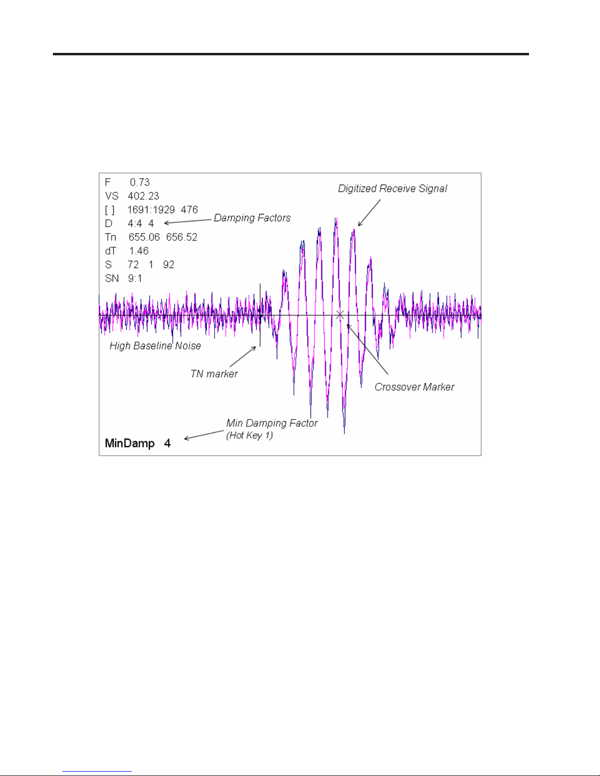
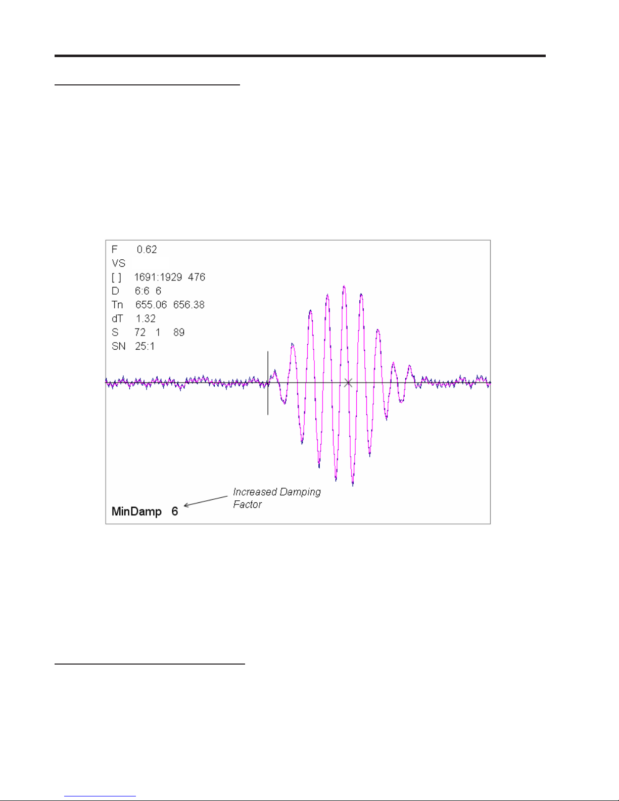
z The Test Facilities Graphic Screen will appear on the meter display as shown below.
Setting the Digital Damping Factor to a value HIGHER than the default value of 4 may be necessary
in cases where the signal to noise ratio (SN) is found to be unacceptably low (<15:1), but only if the
noise is determined to be asynchronous (i.e., not associated with the transmit or flowmeter timing
circuitry) as shown in the signal example above, where the baseline noise has a higher frequency
than the true gas signal.
The following application conditions may require a higher Digital Damping Factor:
z Close proximity to pressure control valves which may generate in-band acoustic noise
z Very low acoustic signal levels (ALC < 40%)
z High electronic noise from variable frequency drives or other external equipment.
A-2
Manual Addendum
1010FMA-58
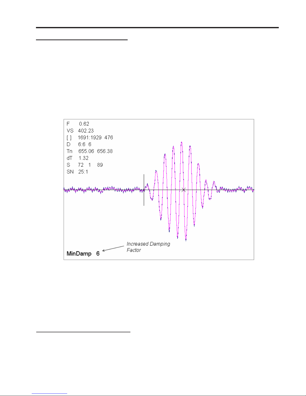
To INCREASE the Digital Damping:
1. Press the <1> key while viewing the Test Facilities Graph Screen as shown above. The damping
control [MinDamp #] should appear on the command line at the lower left-hand corner of the
screen.
Note: The number listed to the right of the command code on the screen represents the
exponent in the exponential averaging routine, where the larger the number represents
the greater the digital averaging. Setting this exponent higher than 7 is generally not
recommended.
2, Pressing the <+> key will increase the MinDamp Factor by one unit for each key press. To exit this
mode, press the <0> key on the keypad.
The above example shows that increasing the Digital Damping reduces asynchronous noise.
Setting the Digital Damping factor to a value LOWER than the default value of 4 may be justified in
cases where pulsating flow is present (such as from a reciprocating compressor) or for the purpose
of diagnosing transient signal behavior. A pulsating flow condition that generates more than +/- 45
degrees of phase jitter will generally cause signal correlation problems when any digital averaging is
used. In this case it may be necessary to completely eliminate the digital averaging by reducing the
Digital Damping Factor to 0. In such a case it may also be necessary to install a narrow band tuned
amplifier (Input Module) if too much asynchronous noise exists.
To DECREASE the Digital Damping:
1. Press the <2> key while viewing the T est Facilities Graph Screen. The damping control [MaxDamp
#] should appear on the command line at the lower left-hand corner of the screen.
2. Pressing the <-> key will decrease the MaxDamp Factor by one unit for each key press. T o exit this
mode, press the <0> key on the keypad.
A-3

Manual Addendum
1010FMA-58
Liquid Clamp-on Flowmeter Manuals
Replace the Digital Damping Control: (Hot Key 1 and 2) procedure in the “Detection Modes” section
(sub-paragraph: Command Modes) in the following flowmeter manuals:
FUS1010 IP 65 (NEMA 4X) Clamp-On Flowmeter manual (CQO:1010NFM-3)
FUE1010 IP 65 (NEMA 4X) Clamp-On Flowmeter manual (CQO:1010ENFM-3)
FUH1010 IP 65 (NEMA 4X) Clamp-On Flowmeter manual (CQO:1010DVNFM-3)
FUH1010 IP 65 (NEMA 4X) Clamp-On Flowmeter manual (CQO:1010PVNFM-3)
FUP1010 IP 40 (NEMA 1) Clamp-On Portable Flowmeter manual (CQO:1010PFM-3)
FUE1010 IP 40 (NEMA 1) Clamp-On Portable Flowmeter manual (CQO:1010EPFM-3)
Digital Damping Control: (Hot Key 1 and 2)
The meter permits user modification of the digital averaging used by the signal processing routines. In
general, the default damping values selected by the METER will provide optimal performance over a
wide range of transit time applications. However, in extreme cases of unstable flow , pulsating flow , low
signal levels or high electronic noise it may be necessary to override these default settings to permit
uninterrupted and reliable flow measurement.
Test Facilities Graph Screen
The Graph Screen includes the capability to access a set of command codes, which enable a user to
override a number of default meter settings. The most important parameter is the digital damping
control, which can be accessed by pressing number <1> or <2> on the keypad while in the Signal
Graph Screen mode.
[MinDamp] Command
Pressing the <1> key will cause [MinDamp #] to appear on the command line at the lower left-hand
corner of the screen. The number listed to the right of the command code represents the exponent in
the meter exponential averaging routine, where the larger the number the greater the digital averaging.
Pressing the <+> key will increase the damping value. Likewise, pressing the <-> key will decrease
the damping value. To exit this mode, press the <0> key on the keypad.
[MaxDamp] Command
Pressing the <2> key will bring up the [MaxDamp] command. The function of this parameter is similar
to the [MinDamp] command described above; however, the two parameters interact in the following
manner. The MinDamp value must not exceed the MaxDamp value, therefore increasing the MinDamp
value above the previous MaxDamp value will set both parameters to the same value. In most cases,
it is preferred that both damping parameters be set to the same value, however , in cases where rapid
response to changes in liquid sound velocity for flow rate is required, the two values may be set
differently . In this situation the meter will use the MaxDamp value when conditions are stable, but then
switch to a faster damping value (limited by MinDamp) when a significant change in sound velocity or
flow rate is perceived. To exit this mode, press the <0> key on the keypad.
A-4
Manual Addendum
1010FMA-58
To access the Digital Damping Control using the Test Facilities Graph Screen, proceed as follows:
1. To use the Test Facilities Graph Screen you must have a working site.
2. To activate the Test Facilities Graph Screen:
z In the main menu, scroll to the [Diagnostic Data] menu and select [Test Facilities].
z Scroll down to [Graph], press the <Right Arrow> and highlight [Yes]. Press <ENT> to select.
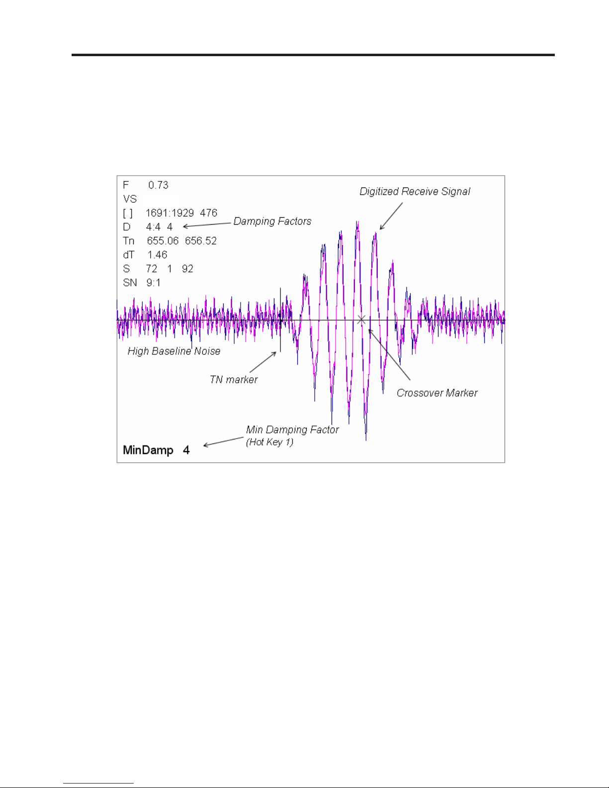
z The Test Facilities Graphic Screen will appear on the meter display as shown below.
1482.1
Setting the Digital Damping Factor to a value HIGHER than the default value of 4 may be necessary in
cases where the signal to noise ratio (SN) is found to be unacceptably low (<15:1), but only if the noise
is determined to be asynchronous (i.e., not associated with the transmit or flowmeter timing circuitry)
as shown in the signal example above, where the baseline noise has a higher frequency than the true
liquid signal.
The following application conditions may require a higher Digital Damping Factor:
z Close proximity to pressure control valves which may generate in-band acoustic noise
z High un-dissolved gas solids content in liquid.
z High electronic noise from variable frequency drives or other external equipment.
A-5
Manual Addendum
1010FMA-58
To INCREASE the Digital Damping:
1. Press the <1> key while viewing the Test Facilities Graph Screen as shown above. The damping
control [MinDamp #] should appear on the command line at the lower left-hand corner of the
screen.
Note: The number listed to the right of the command code on the screen represents the
exponent in the exponential averaging routine, where the larger the number represents
the greater the digital averaging. Setting this exponent higher than 7 is generally not
recommended.
2. Pressing the <+> key will increase the MinDamp Factor by one unit for each key press. To exit this
mode, press the <0> key on the keypad.
1482.1
The above example shows that increasing the Digital Damping reduces asynchronous noise.
Setting the Digital Damping factor to a value LOWER than the default value of 4 may be justified in
cases where pulsating flow is present (such as from a reciprocating pump) or for the purpose of
diagnosing transient signal behavior. A pulsating flow condition that generates more than +/- 45 degrees
of phase jitter will generally cause signal correlation problems when any digital averaging is used. In
this case it may be necessary to completely eliminate the digital averaging by reducing the Digital
Damping Factor to 0.
To DECREASE the Digital Damping:
1. Press the <2> key while viewing the Test Facilities Graph Screen. The damping control [MaxDamp
#] should appear on the command line at the lower left-hand corner of the screen.
2. Pressing the <-> key will decrease the MaxDamp Factor by one unit for each key press. T o exit this
mode, press the <0> key on the keypad.
A-6

MANUAL
ADDENDUM
1010FMA-22
System 1010AP/AER
Ultrasonic Aerospace
Portable Flowmeter
Manual Addendum
1010FMA-22
March 2007
Copyright © 2007 Siemens Industry, Inc all Rights Reserved Made in the USA


1010AERWDP TRANSDUCER INSTALLATION
1. INTRODUCTION
The System 1010AERWDP flowmeters are part of Siemens extensive System FUS 1010 ClampOn Transit-Time Ultrasonic Flowmeter division. These meters have all the capabilities of the
FUS1010 Clamp-On Series flowmeters plus all the added features of the Aerospace line, which
is specifically designed to accurately and non-intrusively measure flow in steel, aluminum,
and titanium tubing typically used in aircraft hydraulic and fuel systems.
NOTE: If not installing aerospace transducers refer to the FUP1010 Portable Flow-
meter Field Manual instead.
2. FLOWMETER SETUP
NOTE: If flowmeter is already installed at the site disregard the following set up proce-
dure.
The following instructions require the use of the FUP1010 Flowmeter keypad and menus. The
installer should become familiar with them before proceeding further. Refer to Tables 1 and 2
as needed for menu setup data. In addition, refer to Section 2 - The Installation Menu in the
appropriate flowmeter field manual.
To set up the flowmeter with the Aerospace Transducer, proceed as follows:
Selecting Aerospace Transducer
z Switch the flowmeter on. Press the <MENU> key.
Siemens Site [1]
Select Meter Type
Meter Type >Dual Channel Flow
Meter Facilities
z Press <Right> arrow key to select “Dual Channel Flow” mode. To select, press <ENT>
key.
z Press <Right> arrow key and then the <Down> arrow key to select Aerospace, then
press the <ENT> key.
Siemens Site [1]
Dual Channel Flow Setup
Dual Channel Flow >Aerospace
Clamp-on
Flow Tube
Reflexor
Single Channel
1

Creating a New Site Setup (See also paragraph 2.1.3 in 1010P Field Manual)
This section provides an example of how to use the [Create/Rename Site] command to create a
new site setup. Always begin a new installation by issuing the [Create/Name Site] command.
Although you do not need to enter a site name to create a new site setup, you will have to provide
one to save the site setup or to identify the source of logged data. In this example, [SITE1] will be
used for the site name.
zz
z To access the [Channel Setup] menu press the <Right> arrow, then move the highlight
zz
down to [Create/Name Site].
Siemens Site [1]
Right Arrow & Enter Creates a new Site
Recall Site Setup No Sites
Channel Enable No
Create/Name Site
Site Security Off
Delete Site Security No Sites
Save/Rename Site
Channel Setup
z Press the <Right> arrow. Note that the cursor changes to a block that appears after a
question mark (?). This indicates that you have accessed the first character position of an
eight-character (maximum) alphanumeric entry field.
Siemens Site [1]
Right Arrow & Enter Creates a new Site
Recall Site Setup No Sites
Channel Enable No
Create/Name Site ?
Site Security Off
Delete Site Security No Sites
Save/Rename Site
Channel Setup
z You can create a site name (up to 8 characters) by scrolling through the list of available
This block cursor is
currently placed at the first
character position.
characters, using the <UP> or <Down> arrows or numeric keypad. Pressing the <Right>
arrow advances the cursor to the next character space.
z Once the desired site name is filled in, press the <ENT> key to register the selection.
z Press the <Left> arrow to exit this menu.
2

Selecting Pipe Data
z Press the <Down> arrow to select Pipe Data, then press the <Right> arrow.
Siemens Site [1] SITE1
Enter Pipe Outer Diameter manually
Pipe OD (in) 1.000
Pipe Material Steel
Wall Thickness 0.035
Liner Material None
Liner Thickness 0.000
Pipe Data
z To select Pipe OD (in), press the <Right> arrow. Use numeric keys to change pipe size.
Press the <ENT> key to register data.
z Press the <Down> arrow to select Pipe Material if it is not displayed, then press the
<Right> arrow to select option list.
z Use the <Up> and <Down> keys to scroll the option list for the desired pipe material.
Press the <ENT> key to register data.
z Press <Down> arrow to select Liner Material if it is not displayed, then press the <Right>
arrow to select option list.
z Use the <Up> and <Down> keys to scroll the option list for the desired liner material.
Press the <ENT> key to register data.
z Press the <Down> arrow to select Liner Thickness, then press <Right> arrow. Use nu-
meric keys to change pipe size. Press the <ENT> key to register data.
Liquid Data
z Press the <Down> arrow to select Liquid Data if it is not displayed, then press the <Right>
arrow.
Siemens Site [1] SITE1
Kinematic Viscosity of liquid
Viscosity <cS> 1.00
Density S.G. 1.000
Liquid Data
z Press the <Right> arrow and use numeric keys to change Viscosity <cS>. Press <ENT>
to register data.
z Press the <Right> arrow and use numeric keys to change Density SG. Press <ENT> to
register data.
3

Using the Pick/Install Xdcr Menu
z Press the <Down> arrow to select Pick/Install Xdcr if it is not displayed, then press the
<Right> arrow. The meter will display only the transducers that are suitable for the
entered tube diameter.
The prompt line will display the recommended transducer part number based on the
entered wall thickness as indicated in Table 2 on page 9 of this addendum.
Siemens Site [1] SITE1
Recommended Xdcr: 1011AP-16S2-B
Transducer P/N *1011AP-16S2-B
Install Completed? 1011AP-16S3-B
Empty Pipe Set 1010AP-16S4-B
Zero Flow Adjust Chan Not Setup
Pick/Install Xdcr
z Press the <Right> arrow and scroll to desired transducer P/N (e.g., P/N 1011AP-16S2-B).
z Press the <ENT> key to register your selection.
3. AEROSPACE TRANSDUCER INSTALLATION
Transducer Mounting Procedure
To install the Aerospace Transducer, refer to Installation Drawing 1011AP-8 in this addendum and proceed as follows:
z Apply a thin bead of Super Lube (CC128) to the active area of the transducer.
z Press the transducer onto the tube and snap it into place. Check to make sure that the
transducer makes positive contact with the tube.
Connecting Transducer Cables
NOTE: The 1010 Aerospace Transducer is a bi-directional device. The upstream and
downstream transducer cabling can be interchanged depending on which direction of flow is desired to be positive or negative.
z Connect one end of the BNC transducer cable to the upstream transducer connector
(UP).
z Connect the other end of the flow transducer cable to the UP connector on flowmeter.
z Connect one end of another BNC transducer cable to the downstream transducer connec-
tor (DN).
z Connect the other end of the flow transducer cable to the DN connector on flowmeter.
4

z Press the <Down> arrow to select Install Completed?, then press the <Right> arrow.
Siemens Site [1] SITE1
Key [Install] after mounting transducers
Transducer P/N 1011AP-16S2-B
Install Completed? No
*Install
Empty Pipe Set Chan Not Setup
Zero Flow Adjust Chan Not Setup
Pick/Install Xdcr
z Use the <UP> or <Down> arrows to move the cursor to Install.
z Press the <ENT> key to register selection. The meter will then perform an Initial Makeup,
which conditions its operation to the selected transducer, pipe, and liquid. It then automatically sets the empty pipe and zero flow levels. Be patient, this process may take
several minutes.
Siemens Site [1] SITE1
Drive 10 m 13 [6:----------:0]
Transducer P/N 1011AP-16S2-B
Install Completed? Install
Empty Pipe Set Chan Not Setup
Zero Flow Adjust Chan
Not Setup
Pick/Install Xdcr
z Upon completion the meter reports the measured liquid sonic velocity. To accept the
Measured Vs m/s
1490
Measured Vs, press the <Down> arrow.
NOTE: If you want to correct the reported sound velocity, press the <Right> arrow to
edit the indicated Vs value, then press <ENT> to continue.
NOTE: The meter will now perform an AutoZero operation where the meter measures
any zero flow offset, which is used to correct the flow reading.
Siemens Site [1] SITE1
Set Empty Pipe Detection Threshold
Transducer P/N 1011AP-16S2-B
Install Completed? Yes
Empty Pipe Set MTYmatic
Zero Flow Adjust Actual Zero
Pick/Install Xdcr
5

After the meter completes its Initial Makeup command, the [Installed Completed?] option
list changes to:
Install Completed? Yes
New Makeup
If you want to redo the Initial Makeup, move cursor to New Makeup, then press the <ENT> key.
This resets the option list. You can now repeat the install routine described previously.
z Refer to the FUP1010 Portable field manual for the Empty Pipe Set procedure.
z Refer to the FUP1010 Portable field manual for the Zero Flow Adjust procedure.
NOTE: For additional FUP1010 flowmeter functions refer to the FUP1010PFM-3 field
manual.
6
Pipe Material
Wall Thickness
Liner Material
Liner Thickness
(Select Xdcr)
Install Completed?
Empty Pipe Set
Density S.G.
Zero Flow Adjust
Meter Facilities
Menu does not
include “T able
Setups.” See
1010P manual.
FlowTube*
Clamp-on*
Reflexor*
Single Channel Channel 1 Aerospace Channel Setup
Thickness Gauge
Pipe Data Pipe OD (in)
Flaw Detector
Liquid Data Viscosity cS
Pick/Install Xdcr Transducer P/N
All other menu items are unchanged (see 1010P manual).
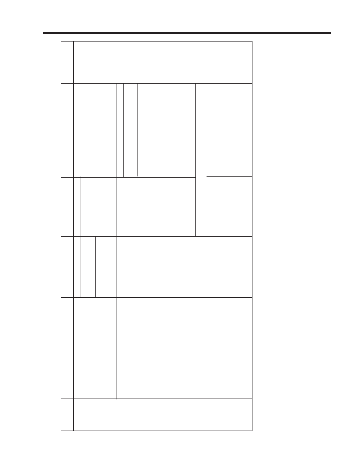
Table 1. System Menu
Level 1 Level 2 Level 3 Level 4 Level 5 Level 6 - Data/Entry Level Comments
Meter Type
Meter
Facilities
* For additional functions refer to the FUP1010 Portable field manual.
7

Wall Thickness Range (in)
OD (in)
1/4 1011AP-4S1-B
1/3 1011AP-5S1-B
3/8 1011AP-6S1-B
1/2 1011AP-8S1-B 1011AP-8S2-B
5/8 1011AP-10S2-B 1011AP-10S3-B
3/4 1011AP-12S2-B 1011AP-12S3-B 1011AP-12S4-B
7/8 1011AP-14S2-B 1011AP-14S3-B 1011AP-14S4-B
1 1011AP-16S2-B 1011AP-16S3-B 1011AP-16S4-B
1 1/8 1011AP-18S2-B 1011AP-18S3-B 1011AP-18S4-B 1011AP-18S5-B
1 1/4 1011AP-20S2-B 1011AP-20S3-B 1011AP-20S4-B 1011AP-20S5-B
1 1/2 1011AP-24S2-B 1011AP-24S3-B 1011AP-24S4-B 1011AP-24S5-B
2 1011AP-32S2-B 1011AP-32S3-B 1011AP-32S4-B 1011AP-32S5-B
0.015 to 0.042 0.015 to 0.042 0.043 to 0.061 0.062 to 0.084 0.085 to 0.116
Table 2. Pipe Outer Dimension and Wall Thickness Chart
NOTE: The 1011AP Aerospace Transducer part number designations are expressed in
1/16-inch increments (e.g., part number 1011AP-4S1-B indicates 4S = 1/4”).
8


 Loading...