

Page 1
SITRADYN EDITION 2
120-W-Vollverstärker
120-W Mixer Power Amplifier
Betriebsanleitung / Operating Instructions Bestell-Nr. / Order No. C98392-A9702-A52-2
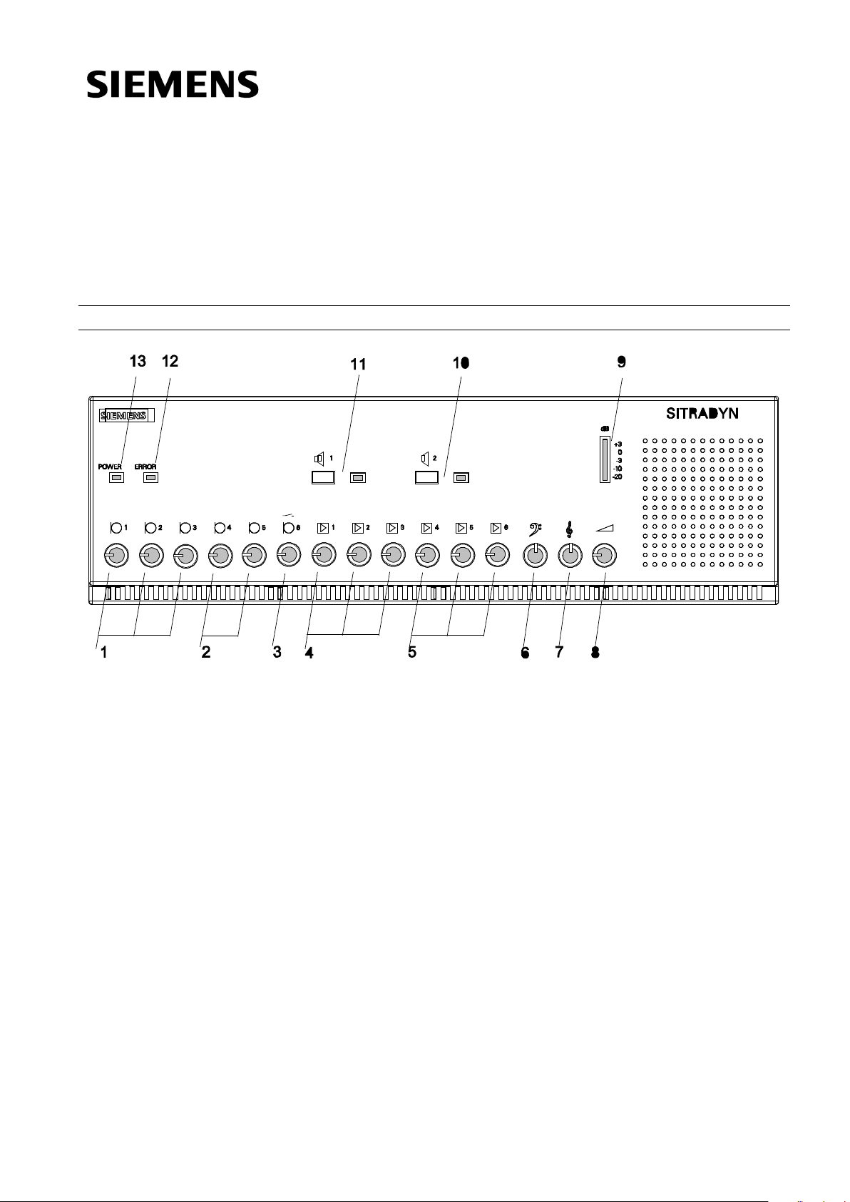
1 Pegelsteller Mikrophoneingang 1-3
2 optioneller Mikrofoneingang 4 und 5
3 Pegelsteller Mikrophoneingang 6 (mit Limiter)
4 Pepelsteller Lineeingang 1-3
5 optioneller Line-/Mikrofoneingang 4-6
6 Tiefensteller
7 Höhensteller
8 Summenpegelsteller
9 Aussteuerungsmesser
10 Lautsprecher-Kreistaste 2 mit LED
11 Lautsprecher-Kreistaste 1 mit LED
12 ERROR LED
13 POWER LED
Anwendungsbereich
Die Vollverstärker sind für hochwertige
Musikübertragungen in Mehrzweckhallen ebenso
geeignet wie für Ruf- und Kommandoanlagen, bei denen
es auf gute silbenverständliche Sprachübertragungen
ankommt.
• 4 Mikrofoneingänge (erweiterbar), einer mit Vorrang
• 3 hochpegelige Line-Eingänge (erweiterbar)
• Einschleifpunkt
• Line-Ausgang
• 2 100 V-Übertragerausgänge, einzeln schaltbar
• 8 Ohm Direktausgang
1 Volume control for microphone input 1-3
2 optional microphone input 4 and 5
3 Volume control for microphone input 6 (with limiter)
4 Volume control for line input 1-3
5 optional line/microphone input 4-6
6 Bass control
7 Treble control
8 Master volume control
9 Level indicator
10 Loudspeaker zone selector 2 with LED
11 Loudspeaker zone selector 1with LED
12 ERROR LED
13 POWER LED
Application
The mixer power amplifier is suited for top-quality music
transmissions in multipurpose halls as well as for paging
and announcement systems that require superior syllabic
articulation in voice transmissions.
• 4 microphone inputs (expandable), one with priority
• 3 high-level line inputs (expandable)
• Insertion point
• Line output
• 2 100 V transformer outputs, each switchable
• direct 8 Ohm output
Page 2
Temp.
Überw
Control.
100V-
Kreis 2
Zone 2.
+54 V
-54 V
+22 V
230 V/115 V
-19 dBu
0 dBu
-19 dBu
-19 dBu
+32 dBu
L1
Vorrang
Priority
Lüfter
Fan
Lautsprecher Kreistaste 1
Loudspeaker zone selector 1
Mute
bei / at
9dBu/-29 dBu
L2
L3
L4
L5
L6
M2
M3
M1
UmM4M5
M6
optional
+3dBu
0dBu
-3dBu
-10dBu
-20dBu
100V-
Kreis 1
Zone 1.
Line-Ausgang
Line out
-3dBu
0dBu
+42.2dBu
0dBu/-3dBu
-3 dB bei/at
TKK=100°C
Start
bei/at
TKK=75°C
TKK=115°C
Mikrofon-
eingang
Mic input
Hochpegel-
eingang
High level
input
+22 V
Betrieb
Operation
Error
Einschleifpunkt
Insertion point
31 V/ 8 Ohm
Direktausgang
Direct output
X110
13X109
X103
1
234
-3dBu
-3dBu
0dBu
unsym.
symm.
3
2
1
X8
X105
Lautsprecher Kreistaste 2
Loudspeaker zone selector 2
Erklärung :
Description :
=
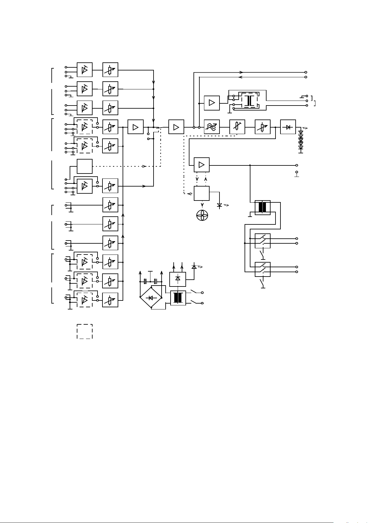
Elektrischer Aufbau
Electrical design
Blockschaltbild
Block diagram
Page 3

Mikrofon-Kanäle 1 bis 3:
Microphone channels 1 to 3:
Der Verstärker hat im Grundausbau 3 elektronisch
symmetrische Eingänge, 1,2 und 3 für dynamische
Mikrofone.
Mikrofon-Kanal 6:
Der symmetrische Eingang 6 mit Limiter ist für dynamische
Mikrofone verwendbar. Er ist mit dem Eingangsverstärkerbaustein -L934 ausgestattet.
Dieser Eingang hat Vorrang gegenüber allen anderen
Eingängen. Wird dieses Mikrofon (mit einer
Kontrollspannung von 0 V) aufgeschalten, werden alle
anderen Eingänge weggeschaltet.
Mikrofon-Erweiterungskanäle 4 und 5:
Die Eingänge 4 und 5 können mit den optionellen
Eingangsverstärkerbausteinen -L930, -L931, -L934, -L939
als Mikrofoneingänge oder als erdfei symmetrische
Hochpegeleingänge verwendet werden.
Eingang 6 hat Priorität gegenüber den Eingängen 1 bis 5
(abschaltbar mit Brücke X105).
Mit dem Universalverstärker mit Schwellwertschalter kann
eine ferngesteuerte Durchschaltung mit Priorität realisiert
werden. D.h. sobald ein am Eingang 6 ankommendes NFSignal einen einstellbaren Pegel überschreitet, werden alle
anderen Eingänge abgeschaltet und dieses NF-Signal wird
durchgeschaltet. Unterschreitet das ankommende Signal die
Schaltschwelle so werden nach Ablauf einer einstellbaren
Abfallzeit wieder alle Eingänge eingeschalten. Für dieser
Funktion muß der Pin 10 des Bausteines mit dem Pin X213
auf der Grundplatine über ein kurzes Kabel verbunden
werden.
In its basic complement, the amplifier features 3
electronically balanced inputs (1,2 and 3) for dynamic
microphones.
Microphone channel 6:
The balanced input 6 with limiter can be used for dynamic
micropones. It is equipped with the input amplifier module
-L934
This input has prioriry against all others. If this micropone is
switched on (with a control voltage of 0 V) all other inputs
will be switched off.
Microphone extension channels 4 and 5:
If inputs 4 and 5 are equipped with the optional input
amplifier modules –L930, -L931, -L934, -L939, they can be
used as microphone inputs or as floating, balanced highlevel inputs.
Input 6 has priority over inputs 1 to 5 (deactivated by jumper
X105).
The universal amplifier with threshold point switch makes it
possible to perform remote-controlled routings with priority
switching. This means that as soon as an AF signal arriving
at input 6 exceeds a preset level, all the remaining inputs
are switched off and the incoming AF signal is throughconnected. If the incoming signal remains under the
switching threshold, all the inputs are switched back on after
a preset fall time. To enable this function, pin 10 of the
module must be connected to pin X213 of the PCB via a
short cable.
Line-Kanäle 1 bis 3:
Die 3 unsymmetrischen Line-Eingänge, 1,2 und 3 sind für
diverse hochpegelige Tonquellen (mit 0 dBu - wie z.B. CDPlayer, Kassettenrecorder) verwendbar.
Line-Erweiterungskanäle 4 bis 6:
Die Eingänge 4 bis 6 können mit optionellen
Eingangsverstärkerbausteinen als erdfei symmetrische
Hochpegeleingänge verwendet werden.
Optionelle Eingangsverstärkerbausteine: -L930, -L932.
Optionelle Eingangsverstärkerbausteinen:
Hochpegelverstärker , unsymmetrisch C98392-A9701-L930
Mikrofonvorverstärker, symmetrisch C98392-A9701-L931
Hochpegelverstärker, symmetrisch C98392-A9701-L932
Mikrofonvorverstärker mit Begrenzer C98392-A9701-L934
Universalverstärker mit Schwellwertschalter C98392-A9701-L939
Optionelle Zusätze:
Sprechstelle, mit Sprechtaste und Mikro TS 01 S8
Line channels 1 to 3:
The three unbalanced line inputs 1, 2 and 3 can be used for
various high-level sound sources (at 0 dBu; e.g. CD player,
tape recorder).
Line extension channels 4 to 6:
When equipped with the optionally available input amplifier
modules, the inputs 4 to 6 can be used as floating balanced
high-level inputs.
Optional input amplifier modules: -L930, -L932.
Optional input amplifier modules:
High-level amplifier , unbalanced C98392-A9701-L930
Microphone preamplifier, balanced C98392-A9701-L931
High-level amplifier, balanced C98392-A9701-L932
Microphone preamplifier with limiter C98392-A9701-L934
Universal amp. with threshold control C98392-A9701-L939
Optional accessoires:
Call Station, with speechbutton and microfone TS 01 S8
Page 4

Inbetriebnahme
Sicherungs-
einheit
Liefer zustand
Fuse unit
Factory setting
How to start the system
Gerät nur von qualifizierten Personen öffnen!
Beachten Sie die Symbole in der Betriebsanleitung und am Gerät:
Weist auf mögliche Gefährdung durch elektrischen Schlag hin.
Weist auf mögliche Gefahrensituation hin, die sich z.B. durch
Nichtbeachtung eines Hinweises in der
Betriebsanleitung ergeben könnte.
Aufstellung / Einbau
Der Verstärker muß so aufgestellt oder eingebaut werden,
daß eine ausreichende Kühlung durch Luftzirkulation
gewährleistet ist. Die maximal zulässige
Umgebungstemperatur darf 70°C nicht überschreiten.
Der Einbau in einen 19„-Schrank ist mit optionellen
Montagewinkel möglich.
Erdung
Das Gerät wird über den Schukostecker geerdet. Sind
mehrere Geräte an den Verstärker angeschlossen, ist
darauf zu achten, daß diese untereinander geerdet sind.
Beipack
Dem Verstärker sind folgende Teile beigepackt:
Mikrofon D65S
1 Stk Netzanschlußleitung
3 Stk XLR Kabelstecker 3-polig Buchse
3 Stk XLR Kabelstecker 3-polig Stift
1 Stk DIN Kabelstecker 6-polig Stift
1 Stk DIN Kabelstecker 8-polig Stift
2 Stk 1,65A-Sicherungen (für 230V).
2 Stk 3,15A-Sicherungen (für 115V).
Einstellen der Versorgungsspannung:
Der Vollverstärker kann bei Auslieferung an 230 V
Netzspannung (50 bis 60 Hz) angeschlossen werden.
Bei Versorgung mit einer Wechselspannung von 115 V ist
die Sicherung (T1,6A) mit der im Beipack (T3,15A) zu
tauschen.
Dazu ist:
1. Netzstecker ziehen
2. die Sicherungseinheit (siehe Bild unten)
herauszunehmen
3. die Sicherung zu tauschen
4. die Sicherungseinheit um 180° gedreht wieder
einzusetzen, sodaß der Pfeil (mit der gewünschten
Versorgungsspannung) auf die Markierung zeigt.
Open amplifier only by qualified personnel!
Consider the symbols in the operating instruction and at the device
It refers to possible danger through electric shock.
It refers to possible danger situation which would result e.g.
through nonobservance of a reference in the
operating instruction.
Mounting/Installation
Mount or install the amplifier in such a way that air can
circulate and thus ensure sufficient cooling. The max.
admissible ambient temperature must not exceed 70°C.
The amplifier can be installed into a 19“ rack by means of an
optional assembly kit.
Grounding
The unit is grounded via the shockproof plug. If several
devices are connected to the amplifier, make sure that
they are grounded mutually.
Accessories
The amplifier comes with the following accessories:
1 Microfone D65S
1 mains connecting cord
3 XLR connector 3 poles female
3 XLR connector 3 poles male
1 DIN connector 6 poles male
1 DIN connector 8 poles male
2 1,65A fuses (for 230V)
2 3.15A fuses (for 115 V)
Setting the supply voltage
The mixer power amplifiers are designed for 230 V mains
voltages (50 to 60 Hz).
If the system is to be supplied with AC voltage of 115 V,
replace the fuse (T1, 6A) with the one included (T3, 15A) in
the accessories.
Proceed as follows:
1. Remove mains plug
2. Remove fuse unit (as shown in figure below)
3. Replace fuse
4. Re-insert fuse unit by turning it by 180°, so that the
arrow (with the required operating voltage) will point to
the mark.
Page 5

Einbau von Eingangsverstärkerbausteinen
Mic 5
Mikrofon-Eingang 1
Bestückt mit
Einbauplatz für Eingangsverstärkerbausteine
Line 6
Mic 4
Line 5
Line 4
Mic 6
1. Nach Ziehen des Netzsteckers Gehäuse öffnen
2. Eingangsverstärkerbausteine in die gewünschten
Kanäle stecken
3. Kappen der jeweiligen Kanäle von der Frontplatte
entfernen
4. Potentiometer mit Achse und Knopf bestücken
Installing input amplifier modules
1. Disconnect mains connector and open casing
2. Insert input amplifier modules into the required
channels
3. Remove caps of the respective channels on the front
panel
4. Fit axle and button to potentiometer
Mic input 1
Fitting position for input amplifier modules
Eingangsverstärkerbaustein mit Limiter -L934
Equipped with
Input amplifier module with limiter-L934
Hinweise
Lautsprecher dürfen an der Ausgangsleiste maximal bis zu
einer Gesamtbelastung von 120 W angeschlossen werden.
Das Parallelschalten der Lautsprecher-Ausgänge mehrerer
Verstärker auf ein Lautsprechernetz ist nicht zulässig.
Die Eingangsleitungen für Mikrofone oder andere
Programmquellen dürfen nicht mit den Ausgangsleitungen der Lautsprecher gemeinsam in einem Rohr
verlegt oder parallel geführt werden. Wird dies nicht
beachtet, kann es wegen der hohen Verstärkung zu
störenden Einstreuungen des Ausgangssignals auf die
Eingänge kommen.
Hints
The total load of loudspeakers connected to the
output terminal strip must not exceed 120 W.
Do not connect the loudspeaker outputs of several
amplifiers in parallel to a common loudspeaker network.
Make sure not to lay the input lines for microphones or
other program sources in the conduit accommodating the
loudspeaker output lines nor to lay them in parallel.
If this instruction is not observed, high amplification can
produce interference of the output signal on the inputs.
Page 6

Brücken
Brücke X105
Funktion
mit den anderen
(Lieferzustand)
Einschleifpunkt
Brücke X110
Inaktiv
gesteckt (Lieferzustand)
Aktiv
Offen
Brücken
Ausgang
X103
X203
(Lieferzustand)
ST4294
Jumper X105
Function
remaining inputs
(factory setting)
Insertion point
Jumper X110
Inactive
Fitted (factory setting)
Active
Open
Jumper
Output
X103
X203
(factory setting)
Transformer option
ST4294
Jumpers
Vorrangschaltung (X105)
Der Mikrofonkanal 6 ist mit einer Vorrangschaltung
ausgestattet. Ein Steuersignal (siehe Steckerbelegung)
schaltet die anderen Eingänge weg.
Durch Stecken von X105 kann der Eingang 6
gleichrangig mit den anderen Eingängen betrieben
werden. Alle Eingänge werden gemischt.
gesteckt Mikrofon-Eingang 6 ist gleichrangig
offen
Einschleifpunkt (X110)
Der Einschleifpunkt ist durch Entfernen der Brücke X110
aktivierbar.
Line-Ausgang mit optionellem Übertrager (X103, X203)
Mikrofon-Eingang 6 hat Vorrang
Priority circuit X105
The optional microphone input 6 is provided with a
priority circuit. A control signal (see connector
assignment) is used to switch off the other inputs.
If you want to deactivate the priority function of input 6
and operate all the inputs at equal priority, fit jumper
X105. In this case, all the inputs will be mixed.
Fitted Mic input 6 has the same priority as
Open
Insertion point (X110)
The insertion point is activated by removing jumper X110.
Line output with optional transformer (X103, X203)
Mic input 6 has priority
Der Line-Ausgang ist ein direkter Ausgang, dessen
Signal vor dem Tiefen-und Höhenentzerrer und vor dem
Summenpegelsteller abgenommen wird.
Der Ausgang kann mit einem Übertrager nachgerüstet
werden. Der Ausgang ist mit max. 600 Ohm/500nF
(≅ 10km Kabelkapazität) belastbar und kurzschlußfest.
1-2 offen 0 dBu, unsymmetrisch
Übertrageroption
0 dBu, erdfrei, symmetrisch
The line output is a direct output. Its signal is monitored
ahead of the bass and treble equaliser and ahead of the
master volume control. The output can be retrofitted with
a transformer. Its maximum load must not exceed 600
Ohm/500 nF (≅ 10km cable capacity) and it is short
circuit-proof.
1-2 open 0 dBu, unbalanced
0 dBu, floating, balanced
Page 7

Steckerbelegung
1
2
3
1
2
3
4
5
7
8
6
Push
Pin
1
2
3
Signal +
Signal -
Pin
1
2
3
4
5
6
7
8 0V/L
0V/A
Signal +
Signal -
+22 V
-
Control
Control
0V/A
1
2
3
4
5
7
8
6
Pin
1 Signal 2
3
0V/A
Signal +
Mikrofoneingang 1 ... 5
Mic input 1 ... 5
Mikrofoneingang 6
Mic input 6
Line-Ausgang
Line output
unsym.
symm.
12345678910
100V
Mi t t e
Cent r e
100V
8 Oh m
0V0V
CASE
12
+ + +- - -
Connector assignment
Schraubklemmen für Leistungsausgänge
Screw terminals for power outputs
Page 8

1 2
3
4
5 6
7
8
9
1 Lautsprecherausgänge
2 Netzanschluß / Ein- Ausschalter / Sicherungseinheit
3 Line-Ausgang (Direktausgang)
4 Einschleifpunkt
5 Pegeltrimmer für Lineeingang 4 bis 6
6 Line-Eingang 1-6
7 Pegeltrimmer für Mikrofoneingang 6
8 Mikrofoneingang 6 mit DIN-Stecker
9 Mikrofoneingang 1-5 mit XLR-Buchse und Pegeltrimmer
1 Loudspeaker outputs
2 Mains / On/Off switch / Fuse box
3 Line output (direct output)
4 Insertion point
5 Input trimmer for line input 4 to 6
6 Line input 4 to 6
7 Input trimmer for mic input 6
8 Mic input 6 with DIN connector
9 Mic input 1-5 with XLR socket and input trimmer
Page 9

Einstellung und Bedienung
Farbe
Nennpegel in dBu
rot
+ 3
gelb
0
grün
- 3
grün
- 10
grün
- 20
Colour
Nominal level in dBu
red
+ 3
yellow
0
green
- 3
green
- 10
green
- 20
Mit den Vorpegelstellern werden die verschiedenen
Tonquellen bei der Inbetriebnahme angepaßt.
1. Summenpegelsteller auf maximale Lautstärke stellen.
2. Pegelsteller des jeweiligen Kanals auf Maximum stellen.
3. Vorpegelsteller so einstellen, daß die gelbe LED des
Aussteuerungsmessers gerade nicht aufleuchtet.
Die Eingangssignale sind mischbar. Während des
Betriebs werden die unterschiedlichen Pegel der
Tonquellen an der Frontplatte eingestellt (abgemischt).
Die Ausgangslautstärke wird mit dem Summenpegelsteller
eingestellt. Wird die Temperatur im Verstärker zu hoch,
wird die Ausgangsleistung um 3 dB reduziert. Die
Lautstärke darf dann nicht erhöht werden. Erhöht sich die
Temperatur weiter schaltet der Verstärker ab. Hat sich der
Verstärker auf Betriebstemperatur abgekühlt schaltet er
sich wieder ein.
Ein unsymmetrischer Ausgang für Tonbandaufnahmen (der
optionell mit einem Übertrager ausgestattet werden kann)
steht auf der Rückseite zur Verfügung.
Die 100-V-Ausgänge sind getrennt aufschaltbar.
Pegelanzeige
Der Ausgangspegel ist mit dem Summenpegelsteller so
einzustellen, daß bei max. möglicher Ausgangsleistung nur
die grünen LED´s aufleuchten. Sobald die gelbe LED öfters
aufleuchtet muß der Pegel zurückgeregelt werden.
Parameter Setting and Operation
The default volume controls are used for adjusting the
various sound sources during commissioning.
1. Position master volume control to maximum volume.
2. Position volume control of relevant channel to
maximum volume.
3. Set default volume control to a position that yellow
LED of level indicator just fails to light up.
The input signals are mixable. During operation the
input levels of the various sound sources can be set
(mixed) individually on the front panel.
The output volume is adjusted by means of the master
volume control. If the temperature in the amplifier exceeds
the permissible value, the output power will be reduced by
3dB and the red ERROR LED will be lit. In this case the
volume must not be increased further. If the temperature
continues to rise, the amplifier will be switched off. After the
amplifier’s temperature has fallen to operating temperature,
the unit is switched back on.
An unbalanced output for tape recordings (which can be
equipped with an optional transformer) is available on the
rear panel.
The 100-V outputs can be connected separately.
Level meter
Use the master volume control to set the output level in such
a way that only the green LEDs will light up, when the
maximum possible output power is reached. As soon as the
yellow LED lights up repeatedly, turn back the level by means
of the master level control.
Klangeinstellung
Mit dem Höhen- und Tiefenentzerrer können Bässe und
Höhen um 13 dB angehoben oder abgesenkt werden. Ein
linearer Verlauf ist in Mittelstellung gegeben. Zur
besseren Sprachverständlichkeit ist es günstig, die Bässe
etwas abzusenken.
Wichtige Betriebshinweise
Die akustische Rückkopplung; deren Einsatz sich durch
Heultöne ankündigt, kann beim Betrieb von Mikrofonen
und Lautsprechern im gleichen Raum entstehen. Bei
großer Lautstärke oder zu kleinem Abstand zwischen
Mikrofon und Lautsprecher kann eine lang anhaltende
akustische Rückkopplung leicht zur Beschädigung der
Lautsprecher führen. Um eine ausreichende Lautstärke
(Aussteuerbarkeit der Verstärker) sicherzustellen, kann
das Einsetzen der Rückkopplung mit folgenden
Maßnahmen erschwert werden; Gerichtete Lautsprecher
wie z.b Gruppenstrahler einsetzen; Richtmikrofone
(rückopplungsarm) verwenden; Abstände zwischen den
Lautsprechern und Mikrofonen vergrößern.
Equalisation
Using the treble and bass equalisers, the high and low
frequencies can be raised or attenuated by 13 dB. Set
switch to central position to obtain a linear frequency
response. For improved intelligibility of speech it is
recommended to slightly mute the bass frequencies.
Important operating instructions
Acoustic feedback, which is signalled by howling sound,
can occur, when microphones and loudspeakers are
operated in the same room. Excessive volume or
insufficient distance between microphone and
loudspeaker may produce persistent acoustic feedback
and damage the loudspeakers. However, to ensure an
appropriate loudness level (amplifier set to full output),
the following measures help to avoid a possible acoustic
feedback:
Use directional speakers, such as loudspeaker groups;
use directional microphones; increase distance between
loudspeakers and microphones.
Page 10

Technische Daten
Mikrofoneingänge
Eingang 1 bis 3 elektron. symmetrisch
Nennpegel bei 600 Ω -51 dBu
Eingangspegelbereich -65 dBu bis -29 dBu
Eingangsimpedanz typ. 1500 Ω / bei 1 kHz
Quellwiderstand 30 bis 600 Ω
Eingang 4 und 5 optionell
Eingang 6 Übertrager, symmetrisch
Eingangspegelbereich -65 dBu bis -29 dBu
Eingangsimpedanz 600 Ω / bei 1 kHz
Lineeingänge
Eingang 1 bis 3 unsymmetrisch
Nennpegel 0 dBu
Eingangswiderstand ≥25 kΩ / bei 1 kHz
Eingang 4 bis 6 optionell
Einschleifpunkt
Ausgang unsymmetrisch
Nennpegel bei 1 kHz, Ra=1 kΩ 0 dBu ± 0.5 dBu
Abschlußimpedanz bei 1 kHz >1 kΩ / max. 100 nF
Eingang unsymmetrisch
Nennpegel 0 dBu
Eingangsimpedanz >2 kΩ
Line-Ausgang (DIN 8-pol.) unsymmetrisch
Nennpegel 0 dBu ± 0,5 dBu
Ausgangsimpedanz bei 1 kHz <40 Ω
Line-Ausgang mit Übertrager*) symmetrisch, erdfrei
Nennpegel 0 dBu ± 1 dBu
Ausgangsimpedanz bei 1 kHz max. 40 Ω
Abweichung
vom linearen Frequenzgang typ. ± 0.5 dB, max. ± 2dB
Klirrfaktor bei 1 kHz typ. 0.1%, max. 0.5 %
Max. Lastimpedanz 600 Ω 100 nF
Ausgang 8 Ω
Max. C-Belastung 1 µF
Kurzschlußstrom typ. 5.5 A
Ausgänge 100 V
Max. C-Belastung 1 µF
Kurzschlußstrom typ. 1,8 A
Ausgangsleistung gesamt typ. 120 W Sinus
typ. 180 W Musik
Übertragungsbereich 40 Hz bis 20 kHz / -3 dB
Entzerrung
bei 40 Hz -14 dB / +13dB
bei 15 kHz -14 dB / +13dB
Klirrfaktor typ.0,3 % bei 1 kHz
Geräuschspannungsabstand typ. 90 dB unbewertet
Betriebsspannung 230/115 V∼, 50 bis 60 Hz
Stromaufnahme bei 230 V
Leerlauf ≤70 mA
Volllast ≤1,6 A
Temperaturbereich 0...+70°C
Lagertemperaturbereich -10 °C bis +85 °C
Rütteln nach
Feuchtigkeit nichtkondensierend 30% bis 70%
Maße BxHxT 432 mm breit
147 mm hoch
326 mm tief
Gewicht etwa 16 kg
EN60065
*) Optionell bestückbar
Das CE-Kennzeichen bestätigt die Übereinstimmung
mit den europäischen Bestimmungen.
Technical Data
Mic inputs
Mic input 1 to 3 electronically balanced
Nominal level at 600 Ω -51 dBu
Input level range -65 dBu to -29 dBu
Input impedance typ. 1500 Ω / at 1 kHz
Source resistance 30 to 600 Ohms
Mic input 4 and 5 optional
Mic input 6 transformer, balanced
Input level range -65 dBu to -29 dBu
Input impedance 600 Ω / at 1 kHz
Line inputs
Line input 1 to 3 unbalanced
Nominal level 0 dBu
Input impedance ≥25 kΩ / at 1 kHz
Line input 4 to 6 optional
Insertion point
Output unbalanced
Nominal level at 1 kHz, Ra=1 kΩ 0 dBu ± 0.5 dBu
Load impedance at 1 kHz >1 kΩ / max. 100 nF
Input unbalanced
Nominal level 0 dBu
Input impedance >2 kΩ
Line output (DIN 8-pin) unbalanced
Nominal level 0 dBu ± 0.5 dBu
Output impedance at 1 kHz <40 Ω
Line output with transformer*) balanced, floating
Nominal level 0 dBu ± 1 dBu
Output impedance at 1 kHz max. 40 Ω
Deviation
from linear frequency response typ. ± 0.5 dB, max. ± 2dB
Distortion at 1 kHz typ. 0.1%, max. 0.5 %
Max. load impedance 600 Ω 100 nF
Output 8 Ω
Max. C load 1 µF
Short circuit current typ. 5.5 A
Outputs 100 V
Max. C load 1 µF
Short circuit current typ. 1.8 A
Total output power typ. 120 W sine
typ. 180 W music
Frequency range 40 Hz to 20 kHz / -3 dB
Equalisation
at 40 Hz -14 dB / +13dB
at 15 kHz -14 dB / +13dB
Distortion factor typ.0.3 % at 1 kHz
Signal-to-noise-ratio typ. 90 dB, unweighted
Operating voltage 230/115 V∼, 50 to 60 Hz
Current consumption at 230 V
at no-load ≤70 mA
at full power ≤1,6 A
Temperature range 0...+70°C
Storage temperature range -10 °C to +85 °C
Shock resistance acc. to EN60065
Humidity, non-condensing 30% to 70%
Dimensions (WxHxD) 432 mm (W)
147 mm (H)
326 mm (D)
Weight approx. 16 kg
*) Optional
The CE Mark indicates the accorance to the european
standards.
Siemens Aktiengesellschaft Österreich Bestell-Nr. / Order No. C98392-A9702-A52-2-7419
Printed in Austria
Änderungen vorbehalten / Subject to change
AG 2.99 1.0 RN 10 de
 Loading...