

Siemens SITOP PSU8200 24 V/20 A, SITOP PSU8200 24 V/40 A, SITOP PSU8200 48 V/20 A, SITOP PSU8200 36 V/13 A, SITOP PSU8200 48 V/10 A User Manual
...
___________________
___________________
___________________
___________________
___________________
___________________
___________________
___________________
___________________
___________________
___________________
___________________
SITOP power supply
SITOP PSU8200/3800 3ph
Manual
SITOP PSU8200 24 V/20 A
6EP3436
SITOP PSU8200 24
6EP1437
SITOP PSU8
6EP3437
SITOP PSU8200 36 V/13 A
6EP3446
SITOP PSU8200 48
6EP3446
SITOP PSU8200 48 V/20 A
6EP3447
SITOP PSU3800 12 V/20 A
6EP3424
SITOP PSU3800 24 V/17 A
6EP3436
SITOP PSU3800 24
6EP3437
05.2018
C98130
Overview
Notes on safety
1
Description, device design,
dimension drawing
2
Mounting/removing
3
Mounting position, mounting
clearances
4
Installation
5
Technical data
6
Safety, approvals, EMC
7
Ambient conditions
8
Applications
9
Environment
10
Service & Support
11
-8SB00-0AY0
V/40 A
-3BA10
200 24 V/40 A
-8SB00-0AY0
-8SB10-0AY0
V/10 A
-8SB00-0AY0
-8SB00-0AY0
-8UB00-0AY0
-8UB00-0AY0
V/40 A
-8UB00-0AY0
-A7638-A1-6-7629
Siemens AG
Division Process Industries and Drives
Postfach 48 48
90026 NÜRNBERG
GERMANY
C98130-A7638-A1-6-5D29
Ⓟ
Copyright © Siemens AG 2018.
All rights reserved
Legal information
Warning notice system
DANGER
indicates that death or severe personal injury will result if proper precautions are not taken.
WARNING
indicates that death or severe personal injury may result if proper precautions are not taken.
CAUTION
indicates that minor personal injury can result if proper precautions are not taken.
NOTICE
indicates that property damage can result if proper precautions are not taken.
Qualified Personnel
personnel qualified
Proper use of Siemens products
WARNING
Siemens products may only be used for the applications described in the catalog and in the relevant technical
ambient conditions must be complied with. The information in the relevant documentation must be observed.
Trademarks
Disclaimer of Liability
This manual contains notices you have to observe in order to ensure your personal safety, as well as to prevent
damage to property. The notices referring to your personal safety are highlighted in the manual by a safety alert
symbol, notices referring only to property damage have no safety alert symbol. These notices shown below are
graded according to the degree of danger.
If more than one degree of danger is present, the warning notice representing the highest degree of danger will
be used. A notice warning of injury to persons with a safety alert symbol may also include a warning relating to
property damage.
The product/system described in this documentation may be operated only by
task in accordance with the relevant documentation, in particular its warning notices and safety instructions.
Qualified personnel are those who, based on their training and experience, are capable of identifying risks and
avoiding potential hazards when working with these products/systems.
Note the following:
documentation. If products and components from other manufacturers are used, these must be recommended
or approved by Siemens. Proper transport, storage, installation, assembly, commissioning, operation and
maintenance are required to ensure that the products operate safely and without any problems. The permissible
All names identified by ® are registered trademarks of Siemens AG. The remaining trademarks in this publication
may be trademarks whose use by third parties for their own purposes could violate the rights of the owner.
We have reviewed the contents of this publication to ensure consistency with the hardware and software
described. Since variance cannot be precluded entirely, we cannot guarantee full consistency. However, the
information in this publication is reviewed regularly and any necessary corrections are included in subsequent
editions.
for the specific
05/2018 Subject to change
Overview
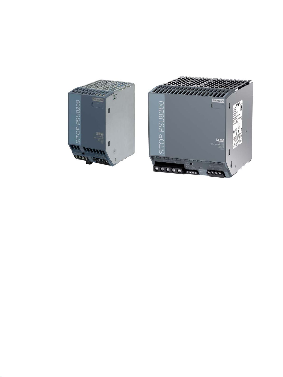
The 3-phase power supply from the SITOP PSU8200 product line is the powerful, regulated
technology power supply for automated machines and systems.
The 3-phase power supply from the PSU3800 product line is the power supply optimized for
charging batteries.
The key benefits of the product include:
● Wide-range input, which allows it to be connected to almost any 3-phase line supply
around the world
● The output voltage can be adjusted in the range 12 - 14 V/24 - 28 (28.8) V/36 - 42 V/
42 - 56 V
● Power boost during operation with 300% rated current for 25 ms (only PSU8200)
● Extra-Power with 1.5x rated current for 5 seconds for switching on loads with a high
inrush current (only PSU8200)
● Especially low width without requiring any lateral mounting clearances
● Ambient temperature -25 ... 70 °C
● Selectable short-circuit response (constant current or latching shutdown)
● A soft characteristic can be selected for a parallel connection (for uniform load distribution
of power supply units of the same type)
SITOP PSU8200/3800 3ph
Manual, 05.2018, C98130-A7638-A1-6-7629
● 3 LEDs are used to display the operating state
● Signaling contact "12 V O.K"/"24 V O.K"/"36 V O.K"/"48 V O.K"
3

Overview
Ordering data
Regulated power supply unit SITOP PSU8200/3800 3ph
Type
Order number
Output 24 V DC / 40 A
Output 24 V DC / 40 A
Output 36 V DC / 13 A
Output 48 V DC/10 A
Output 48 V DC/20 A
Output 12 V DC / 20 A
Output 24 V DC/17 A
Output 24 V DC / 40 A
Accessories
Type
Order number
Device identification labels 20 mm × 7 mm, Ti grey
3RT2900-1SB20
● To increase the system availability, these reliable power supplies can be expanded using
SITOP supplementary modules (redundancy module, selectivity module, buffer module),
as well as SITOP DC-UPS modules
● The properties of the PSU3800 power supplies makes them ideal for battery charging
The following device versions are available:
Input 3AC 400 - 500 V,
Output 24 V DC / 20 A
Input 3AC 400 - 500 V,
Input 3AC 400 - 500 V,
Input 3AC 400 - 500 V,
Input 3AC 400 - 500 V,
Input 3 AC 400 - 500 V,
Input 3AC 400 - 500 V,
Input 3AC 400 - 500 V,
Input 3AC 400 - 500 V,
6EP3436-8SB00-0AY0
6EP1437-3BA10
6EP3437-8SB00-0AY0
6EP3446-8SB10-0AY0
6EP3446-8SB00-0AY0
6EP3447-8SB00-0AY0
6EP3424-8UB00-0AY0
6EP3436-8UB00-0AY0
6EP3437-8UB00-0AY0
SITOP PSU8200/3800 3ph
4 Manual, 05.2018, C98130-A7638-A1-6-7629

Overview
Validity
This manual provides information on the following products:
● SITOP PSU8200 20 A 3ph
Article number: 6EP3436-8SB00-0AY0
Product state: 2
Changes with respect to the previous version (PS 1):
- remote terminal has been added
- various technical data (e.g. setting range U
out
, U
in the case of a fault) changed
out max
SITOP PSU8200/3800 3ph
Manual, 05.2018, C98130-A7638-A1-6-7629
5

Overview
SITOP PSU8200/3800 3ph
6 Manual, 05.2018, C98130-A7638-A1-6-7629

Table of contents
Overview................................................................................................................................................. 3
1 Notes on safety ....................................................................................................................................... 9
2 Description, device design, dimension drawing...................................................................................... 11
3 Mounting/removing ............................................................................................................................... 25
4 Mounting position, mounting clearances ................................................................................................ 27
5 Installation ............................................................................................................................................ 49
1.1 General safety instructions ....................................................................................................... 9
1.2 Safety instructions for hazardous zones ................................................................................. 10
1.2.1 SITOP PSU8200 (6EP3436-8SB00-0AY0, 6EP3437-8SB00-0AY0, 6EP3446-8SB100AY0, 6EP3446-8SB00-0AY0, 6EP3447-8SB00-0AY0) and
SITOP PSU3800 (6EP3424-8UB00-0AY0, 6EP3436-8UB00-0AY0, 6EP3437-8UB00-
0AY0) ...................................................................................................................................... 10
1.2.2 SITOP PSU8200 (6EP1437-3BA10) ...................................................................................... 10
2.1 Device description ................................................................................................................... 11
2.2 Connections and terminal designation.................................................................................... 12
2.3 Potentiometer .......................................................................................................................... 13
2.4 Status displays and signaling ................................................................................................. 14
2.5 Change-over switch ................................................................................................................ 18
2.6 Block diagram ......................................................................................................................... 20
2.7 Dimensions and weight ........................................................................................................... 23
4.1 Standard mounting position .................................................................................................... 27
4.2 Other mounting positions ........................................................................................................ 31
4.2.1 6EP3436-8SB00-0AY0 ........................................................................................................... 31
4.2.2 6EP1437-3BA10 ..................................................................................................................... 33
4.2.3 6EP3446-8SB10-0AY0 ........................................................................................................... 35
4.2.4 6EP3446-8SB00-0AY0 ........................................................................................................... 37
4.2.5 6EP3424-8UB00-0AY0 ........................................................................................................... 39
4.2.6 6EP3436-8UB00-0AY0 ........................................................................................................... 41
4.2.7 6EP3437-8SB00-0AY0 ........................................................................................................... 43
4.2.8 6EP3447-8SB00-0AY0 ........................................................................................................... 45
4.2.9 6EP3437-8UB00-0AY0 ........................................................................................................... 47
5.1 Line-side connection ............................................................................................................... 49
5.2 Output-side connection ........................................................................................................... 51
SITOP PSU8200/3800 3ph
Manual, 05.2018, C98130-A7638-A1-6-7629
7

Table of contents
6 Technical data ...................................................................................................................................... 53
7 Safety, approvals, EMC ........................................................................................................................ 85
8 Ambient conditions ................................................................................................................................ 91
9 Applications .......................................................................................................................................... 93
10 Environment ........................................................................................................................................ 105
11 Service & Support ................................................................................................................................ 107
6.1 Input ....................................................................................................................................... 53
6.2 Output .................................................................................................................................... 56
6.3 Efficiency ................................................................................................................................ 71
6.4 Closed-loop control ................................................................................................................ 77
6.5 Protection and monitoring ...................................................................................................... 78
6.6 MTBF ..................................................................................................................................... 79
6.7 Mechanical system ................................................................................................................ 80
6.8 Accessories ............................................................................................................................ 83
6.9 Dimension drawing ................................................................................................................ 83
7.1 Safety ..................................................................................................................................... 85
7.2 Test voltage ............................................................................................................................ 86
7.3 Approvals ............................................................................................................................... 88
7.4 EMC ....................................................................................................................................... 89
9.1 Parallel connection to increase power rating ......................................................................... 93
9.2 Parallel connection for redundancy ....................................................................................... 95
9.3 Series connection for increased voltage ................................................................................ 97
9.4 Overload protection in the 24 V output circuit ........................................................................ 98
9.5 Protection against short-time voltage dips ............................................................................. 99
9.6 Protecting against longer power failures .............................................................................. 100
9.7 Battery charging with SITOP PSU3800 ............................................................................... 102
SITOP PSU8200/3800 3ph
8 Manual, 05.2018, C98130-A7638-A1-6-7629

1
1.1
General safety instructions
WARNING
Correct handling of the devices
When operating electrical devices, it is inevitable that certain components will carry
dangerous voltages.
Therefore, failure to handle the units properly can result in death or serious physical injury
as well as extensive property damage.
Only appropriately qualified personnel may work on or in the vicinity of this equipment.
Perfect, safe, and reliable operation of this equipment is dependent on proper transportation,
storage, installation and mounting.
Before installation or maintenance work can begin, the system's main switch must be
switched off and measures taken to prevent it being switched on again.
If this instruction is not observed, touching live parts can result in death or serious injury.
SITOP PSU8200/3800 3ph
Manual, 05.2018, C98130-A7638-A1-6-7629
9
Notes on safety
1.2
Safety instructions for hazardous zones
1.2.1
SITOP PSU8200 (6EP3436-8SB00-0AY0, 6EP3437-8SB00-0AY0, 6EP34468SB10-0AY0, 6EP3446-8SB00-0AY0, 6EP3447-8SB00-0AY0) and
SITOP PSU3800 (6EP3424-8UB00-0AY0, 6EP3436-8UB00-0AY0, 6EP34378UB00-0AY0)
WARNING
WARNING
WARNING
1.2.2
SITOP PSU8200 (6EP1437-3BA10)
WARNING
1.2 Safety instructions for hazardous zones
The devices comply with ATEX directive 2014/34/EU; EN 60079-0; EN 60079-15.
UNDER NO CIRCUMSTANCES MAKE ANY VOLTAGE ADAPTATIONS OR CHANGE DIP
SWITCH SETTINGS IN EXPLOSIVE ATMOSPHERES
EXPLOSION HAZARD – SUBSTITUTION OF COMPONENTS MAY IMPAIR SUITABILITY
FOR CLASS I, DIVISION 2
EXPLOSION HAZARD – DO NOT CONNECT OR DISCONNECT EQUIPMENT UNLESS
POWER HAS BEEN SWITCHED OFF OR THE AREA IS KNOWN TO BE NONHAZARDOUS
OPERATE POTENTIOMETERS OR SWITCHES IN NON-HAZARDOUS AREAS ONLY!
SITOP PSU8200/3800 3ph
10 Manual, 05.2018, C98130-A7638-A1-6-7629
2
2.1
Device description
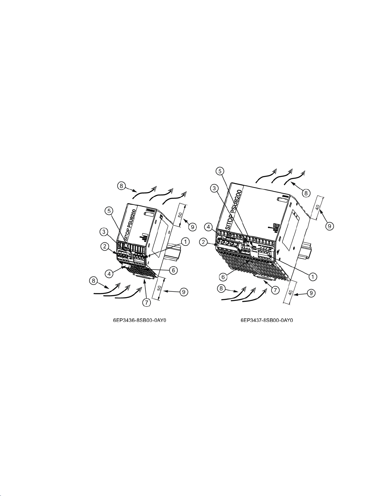
①
AC input
②
DC output
③
Potentiometer (output voltage)
④
Signaling contact, remote (not for 6EP1437-3BA10)
⑤
Indicator lights (OUTPUT O.K., OVERLOAD, SHUTDOWN)
⑥
Selector switch (ON - OFF)
⑦
DIN rail slider
⑧
Convection
⑨
Clearance above/below
SITOP PSU8200/3800 3ph is a primary-clocked power supply for connection to a 3-phase
AC line supply. An electronically regulated DC voltage that can be set via a potentiometer is
available at the output of the device. The output of the device is isolated, no-load proof and
short-circuit proof. The LED displays indicate the operating state. The operating state of the
device can be processed via the signaling contact. Remote control and remote reset are
possible via the remote ON/OFF.
Figure 2-1 Design
SITOP PSU8200/3800 3ph
Manual, 05.2018, C98130-A7638-A1-6-7629
11
Description, device design, dimension drawing
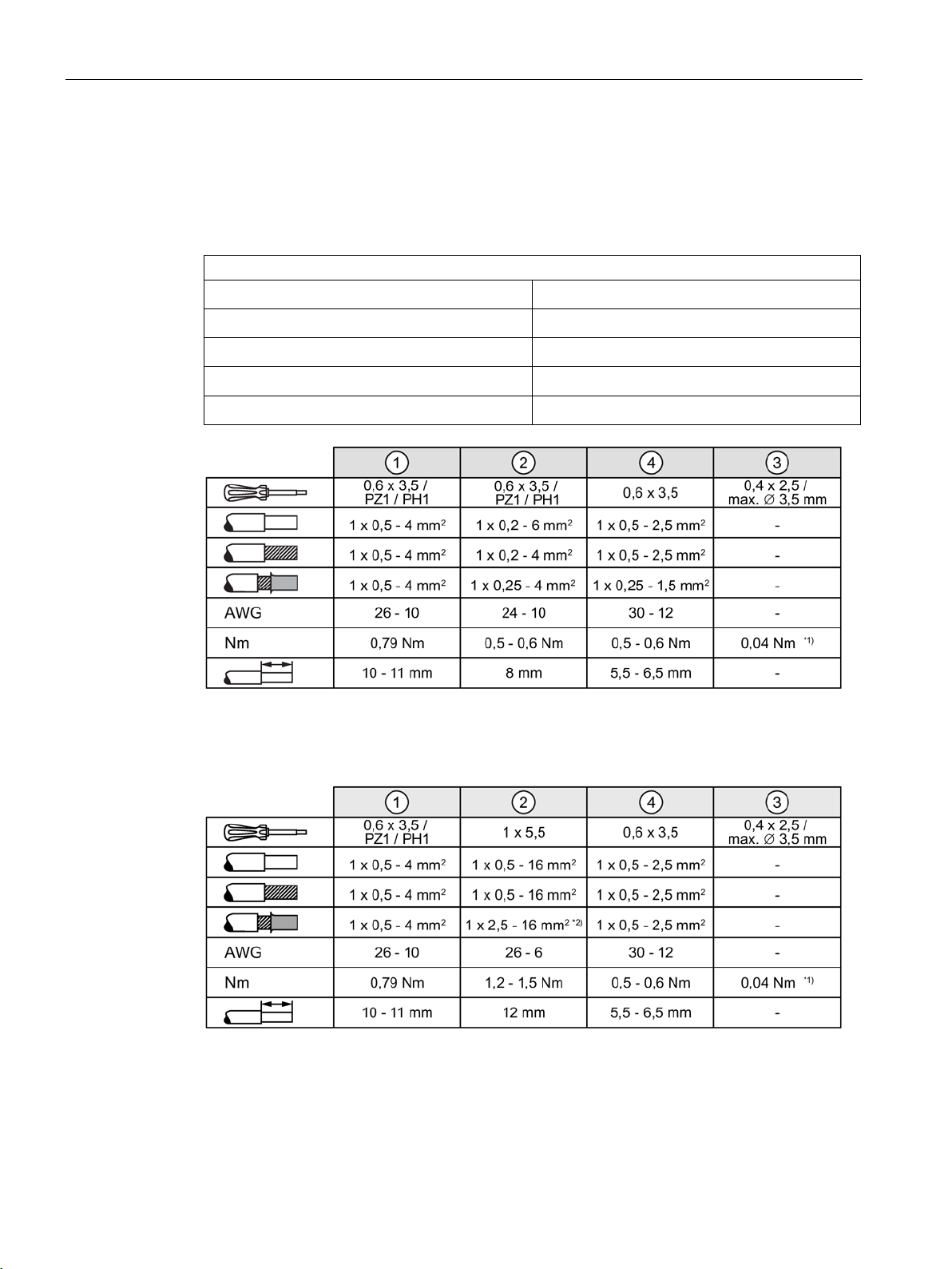
2.2
Connections and terminal designation
Connections and terminal designations
①
②
②
④
④
Do not subject the end stop to higher loads
Do not subject the end stop to higher loads
16 mm2 for square crimping, otherwise 10 mm2
2.2 Connections and terminal designation
The line input terminals ① can be used to establish the connection to the supply voltage.
The output terminals
② are used to connect to the loads to be supplied (see also Section
Installation (Page 49)).
Line input L1, L2, L3, PE
Output +
Output –
Signaling contact 13, 14
Remote contact 15, 16
*1)
Figure 2-2 Terminal data for 6EP3436-8SB00-0AY0, 6EP3446-8SB10-0AY0, 6EP3446-8SB00-
0AY0, 6EP3424-8UB00-0AY0 and 6EP3436-8UB00-0AY0
One screw terminal each
2 screw terminals
2 screw terminals
One screw terminal each
One screw terminal each
*1)
*2)
Figure 2-3 Terminal data for 6EP3437-8SB00-0AY0, 6EP3447-8SB00-0AY0, 6EP1437-3BA10 and
SITOP PSU8200/3800 3ph
12 Manual, 05.2018, C98130-A7638-A1-6-7629
6EP3437-8UB00-0AY0
Description, device design, dimension drawing
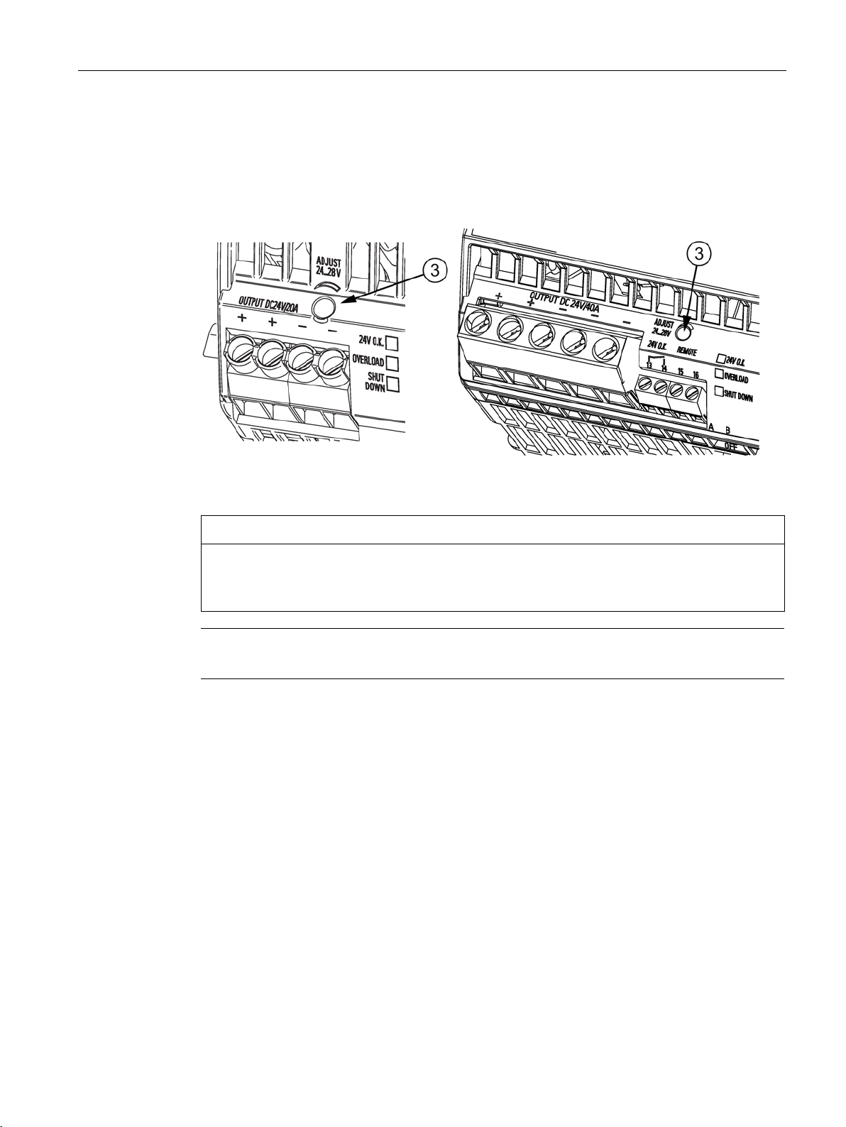
2.3
Potentiometer
NOTICE
Thermal overload possible
Note
It is only permissible to use an insulated screwdriver when
2.3 Potentiometer
The potentiometer ③ at the front of the device is used to adjust the output voltage.
The output voltage is set to U
in the factory, and can be changed – for instance to
out rated
compensate voltage drops along long power supply cables up to the load.
Figure 2-4 Potentiometer
When adjusting the output voltage U
, the output current must be derated by 4 %/V, or
out rated
the permissible ambient temperature must be taken into account with 3 °C/V.
actuating the potentiometer.
For notes on actuating the potentiometer (screwdriver, torque), see Figure 2-2 Terminal data
for 6EP3436-8SB00-0AY0, 6EP3446-8SB10-0AY0, 6EP3446-8SB00-0AY0, 6EP34248UB00-0AY0 and 6EP3436-8UB00-0AY0 (Page 12) and Figure 2-3 Terminal data for
6EP3437-8SB00-0AY0, 6EP3447-8SB00-0AY0, 6EP1437-3BA10 and 6EP3437-8UB000AY0 (Page 12)
SITOP PSU8200/3800 3ph
Manual, 05.2018, C98130-A7638-A1-6-7629
13

Description, device design, dimension drawing
2.4
Status displays and signaling
6EP3436-8SB00-0AY0
(24 V/20 A)
6EP1437-3BA10
(24 V/40 A)
6EP3437-8SB00-0AY0
(24 V/40 A)
(LED flashes)
(LED flashes)
"24 V O.K."
"24 V O.K."
"24 V O.K."
circuited (R < 8 kΩ).
6EP3446-8SB10-0AY0
(36 V/13 A)
6EP3446-8SB00-0AY0
(48 V/10 A)
6EP3447-8SB00-0AY0
(48 V/20 A)
(LED flashes)
(LED flashes)
"36 V O.K."
"48 V O.K."
"48 V O.K."
circuited (R < 8 kΩ).
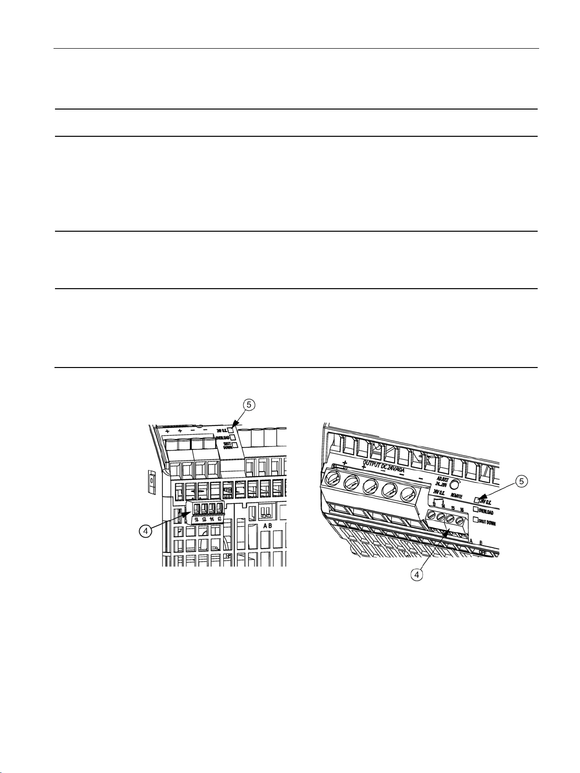
2.4 Status displays and signaling
Operating display ⑤
Signaling contact 13, 14 ④
Remote contact 15, 16 ④
LED green for "24 V O.K."
Yellow LED for overload in
"constant current" mode
Red LED for latching shut-
down in the "Shut down"
mode, for Remote OFF or for
overtemperature
Relay contact (NO contact,
contact rating (isolated):
30 V AC/0.5 A, 60 V
DC/0.3 A, 30 V DC/1 A) for
Non-isolated input for remote
ON/OFF switching of the
power supply. Function: The
device is remotely switched
off when contacts 15, 16 are
short-circuited (R < 8 kΩ).
LED green for "24 V O.K."
Yellow LED for overload in
"constant current" mode
Red LED for latching shut-
down in "shut down" mode
Relay contact (NO contact,
contact rating (isolated):
30 V AC/0.5 A, 60 V
DC/0.3 A, 30 V DC/1 A) for
- Isolated input for remote
LED green for "24 V O.K."
Yellow LED for overload in
"constant current" mode
Red LED for latching shut-
down in the "Shut down"
mode, for Remote OFF or for
overtemperature
Relay contact (NO contact,
contact rating (isolated):
30 V AC/0.5 A, 60 V
DC/0.3 A, 30 V DC/1 A) for
ON/OFF switching of the
power supply.
Function: The device is remotely switched off when
contacts 15, 16 are short-
Operating display ⑤
Signaling contact 13, 14 ④
Remote contact 15, 16 ④
SITOP PSU8200/3800 3ph
LED green for "36 V O.K."
Yellow LED for overload in
"constant current" mode
Red LED for latching shut-
down in the "Shut down"
mode, for Remote OFF or for
overtemperature
Relay contact (NO contact,
contact rating (isolated):
30 V AC/0.5 A, 60 V
DC/0.3 A, 30 V DC/1 A) for
Non-isolated input for remote
ON/OFF switching of the
power supply. Function: The
device is remotely switched
off when contacts 15, 16 are
short-circuited (R < 8 kΩ).
LED green for "48 V O.K."
Yellow LED for overload in
"constant current" mode
Red LED for latching shut-
down in the "Shut down"
mode or for Remote OFF
Relay contact (NO contact,
contact rating (isolated):
30 V AC/0.5 A, 60 V
DC/0.3 A, 30 V DC/1 A) for
Isolated input for remote
ON/OFF switching of the
power supply.
Function: The device is remotely switched off when
contacts 15, 16 are short-
14 Manual, 05.2018, C98130-A7638-A1-6-7629
Description, device design, dimension drawing
6EP3424-8UB00-0AY0
(12 V/20 A)
6EP3436-8UB00-0AY0
(24 V/17 A)
6EP3437-8UB00-0AY0
(24 V/40 A)
(LED flashes)
(LED flashes)
"12 V O.K."
"24 V O.K."
"24 V O.K."
circuited (R < 8 kΩ).
2.4 Status displays and signaling
Operating display ⑤
Signaling contact 13, 14 ④
Remote contact 15, 16 ④
LED green for "12 V O.K."
Yellow LED for overload in
"constant current" mode
Red LED for latching shut-
down in the "Shut down"
mode, for Remote OFF or for
overtemperature
Relay contact (NO contact,
contact rating (isolated):
30 V AC/0.5 A, 60 V
DC/0.3 A, 30 V DC/1 A) for
Non-isolated input for remote
ON/OFF switching of the
power supply. Function: The
device is remotely switched
off when contacts 15, 16 are
short-circuited (R < 8 kΩ).
LED green for "24 V O.K."
Yellow LED for overload in
"constant current" mode
Red LED for latching shut-
down in the "Shut down"
mode, for Remote OFF or for
overtemperature
Relay contact (NO contact,
contact rating (isolated):
30 V AC/0.5 A, 60 V
DC/0.3 A, 30 V DC/1 A) for
Non-isolated input for remote
ON/OFF switching of the
power supply. Function: The
device is remotely switched
off when contacts 15, 16 are
short-circuited (R < 8 kΩ).
LED green for "24 V O.K."
Yellow LED for overload in
"constant current" mode
Red LED for remote OFF or
for overtemperature (LED
flashes)
Relay contact (NO contact,
contact rating (isolated):
30 V AC/0.5 A, 60 V
DC/0.3 A, 30 V DC/1 A) for
Isolated input for remote
ON/OFF switching of the
power supply.
Function: The device is remotely switched off when
contacts 15, 16 are short-
SITOP PSU8200/3800 3ph
Manual, 05.2018, C98130-A7638-A1-6-7629
Figure 2-5 Operating display and signaling
15

Description, device design, dimension drawing
Signaling
6EP3436-8SB00-0AY0
(24 V/20 A)
6EP1437-3BA10
(24 V/40 A)
6EP3437-8SB00-0AY0
(24 V/40 A)
contact (13, 14) closed
(quiescent position)
(quiescent position)
contact (13, 14) closed
(quiescent position)
(quiescent position)
Signaling
6EP3446-8SB10-0AY0
(36 V/13 A)
6EP3446-8SB00-0AY0
(48 V/10 A)
6EP3447-8SB00-0AY0
(48 V/20 A)
contact (13, 14) closed
(quiescent position)
(quiescent position)
contact (13, 14) closed
2.4 Status displays and signaling
Green LED lit
Signaling contact,
LED off
Signaling contact,
contact (13, 14) opened
Yellow LED lit
Signaling contact,
contact (13, 14) opened
Yellow and green LED lights
Signaling contact,
Red LED lit
Signaling contact,
contact (13, 14) opened
LED flashing red
Signaling contact,
contact (13, 14) opened
Normal operation, output
voltage > 20 V ± 0.5 V
Supply voltage missing
Overload, output voltage
< 20 V ± 0.5 V (only in the
"constant current" mode)
Phase failure, output voltage
O.K.
Latching shutdown
Overtemperature → power
OFF/ON after 3 min
Only for PR1
Normal operation, output
voltage > 20 V ± 0.5 V
Supply voltage missing
Overload, output voltage
< 20 V ± 0.5 V (only in the
"constant current" mode)
- -
Latching shutdown
Overtemperature → power
OFF/ON after 3 min
Normal operation, output
voltage > 20 V ± 1 V
Supply voltage missing
Overload, output voltage
< 20 V ± 1 V (only in the
"constant current" mode)
Latching shutdown
Overtemperature → power
OFF/ON after 3 min
Green LED lit
Signaling contact,
LED off
Signaling contact,
contact (13, 14) opened
Yellow LED lit
Signaling contact,
contact (13, 14) opened
Yellow and green LED lights
Signaling contact,
SITOP PSU8200/3800 3ph
16 Manual, 05.2018, C98130-A7638-A1-6-7629
Normal operation, output
voltage > 30 V ± 0.5 V
No supply voltage
Overload, output voltage
< 30 V ± 0.5 V (only in the
"constant current" mode)
Phase failure, output voltage
O.K.
Normal operation, output
voltage > 40 V ± 0.5 V
No supply voltage
Overload, output voltage
< 40 V ± 0.5 V (only in the
"constant current" mode)
Phase failure, output voltage
O.K.
Normal operation, output
voltage > 44 V ± 2 V
No supply voltage
Overload, output voltage
< 44 V ± 2 V (only in the
"constant current" mode)
-

Description, device design, dimension drawing
Signaling
6EP3446-8SB10-0AY0
(36 V/13 A)
6EP3446-8SB00-0AY0
(48 V/10 A)
6EP3447-8SB00-0AY0
(48 V/20 A)
(quiescent position)
(quiescent position)
Signaling
6EP3424-8UB00-0AY0
(12 V/20 A)
6EP3436-8UB00-0AY0
(24 V/17 A)
6EP3437-8UB00-0AY0
(24 V/40 A)
contact (13, 14) closed
(quiescent position)
(quiescent position)
(quiescent position)
(quiescent position)
2.4 Status displays and signaling
Red LED lit
Signaling contact,
contact (13, 14) opened
LED flashing red
Signaling contact,
contact (13, 14) opened
Green LED lit
Signaling contact,
LED off
Signaling contact,
contact (13, 14) opened
Yellow LED lit
Signaling contact,
contact (13, 14) opened
Latching shutdown Latching shutdown Latching shutdown
- - Overtemperature → power
OFF/ON after 3 min
Normal operation, output
voltage > 10 V ± 0.5 V
Supply voltage missing
Overload, output voltage
< 10 V ± 0.5 V (only in the
"constant current" mode)
Normal operation, output
voltage > 20 V ± 0.5 V
Supply voltage missing
Overload, output voltage
< 20 V ± 0.5 V (only in the
"constant current" mode)
Normal operation, output
voltage > 20 V ± 1 V
Supply voltage missing
Overload, output voltage
< 20 V ± 1 V
Yellow and green LEDs lit
Signaling contact,
contact (13, 14) closed
Red LED lit
Signaling contact,
contact (13, 14) opened
LED flashing red
Signaling contact,
contact (13, 14) opened
Phase failure, output voltage
O.K.
Latching shutdown Latching shutdown Latching shutdown
- - Overtemperature → power
Phase failure, output voltage
O.K.
-
OFF/ON after 3 min
SITOP PSU8200/3800 3ph
Manual, 05.2018, C98130-A7638-A1-6-7629
17
Description, device design, dimension drawing
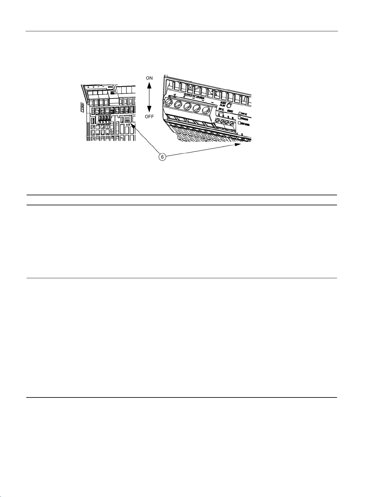
2.5
Change-over switch
Switch
ON
OFF
A
Parallel operation:
Single operation:
pendent of the output current.
B
Latching shutdown:
responds for overload as if the switch is OFF.
Constant current:
2.5 Change-over switch
Figure 2-6 Selector switch A/B
The two switches A and B are used to influence the output characteristic:
influences the output
characteristic in the
load range
influences the output
characteristic in the
overload range
"Soft" characteristic curve (see
characteristic curve 6EP3436-8SB00-0AY0 parallel
operation (Page 65) to Figure 6-19 Output characteristic 6EP3447-8SB00-0AY0 parallel operation
(Page 67)) for parallel operation of two or more devices: The output voltage falls with increasing output
current (namely, also for the overcurrent pulse!).
This means that for full output current the highest
output voltage can normally no longer be attained.
If the output current rises above the rated value and
above the current limit, the device reduces the output
voltage (see
6EP3436-8SB00-0AY0 latching shutdown (Page 68)
to Figure 6-28 Output characteristic 6EP3447-8SB000AY0 latching shutdown (Page 70
voltage falls below 10/20/30/40 or 44 V, the device
shuts down latching, the red LED lights up. This limit
voltage of 10/20/30/40 V is independent of the output
voltage that has been set. The 'Short-time overload
current' feature is not available in this operating mode.
In order to also be able to charge large capacitances
in this operating mode at the output, non-latching
shutdown is performed during the first ten seconds
after power on. During these first 10 s, the device
Figure 6-21 Output characteristic curve
Figure 6-12 Output
)). If the output
delivery condition
"Hard" characteristic (see Figure 6-3
Output characteristic curve 6EP34368SB00-0AY0 single operation (Page 61)
to Figure 6-10 Output characteristic
6EP3447-8SB00-0AY0 single operation
(Page 64
operation): The output voltage is inde-
)) for normal operation (single
delivery condition
The device reduces the output voltage if
the output current exceeds the rated
value and the current limit. The yellow
LED lights up if the output voltage falls
below 10/20/30/40 or 44 V.
SITOP PSU8200/3800 3ph
18 Manual, 05.2018, C98130-A7638-A1-6-7629

Description, device design, dimension drawing
For 6EP3437-8UB00-0AY0 (24 V/40 A)
Switch
ON
OFF
A
Parallel operation:
Single operation:
pendent of the output current.
B
Rated current:
8UB00-0AY0 single operation (Page 70)
Rated current:
Note
Selector switches may only be activated when the device is switched off.
2.5 Change-over switch
influences the output
characteristic in the
load range
is used to switch over
the output current
"Soft" characteristic curve (see
Figure 6-20 Output
characteristic 6EP3437-8UB00-0AY0 parallel operation (B OFF) (Page 67)) for the parallel operation of
two or more devices: The output voltage falls with
increasing output current.
This means that for full output current the highest
output voltage can normally no longer be attained.
= 30 A, no latching shutdown
I
out rated
see
Figure 6-29 Output characteristic 6EP3437-
delivery condition
"Hard" characteristic curve (see Figure 611 Output characteristic 6EP34378UB00-0AY0 single operation (B OFF)
(Page 64
)) for normal operation (single
operation): The output voltage is inde-
delivery condition
I
= 40 A, no latching shutdown
out rated
SITOP PSU8200/3800 3ph
Manual, 05.2018, C98130-A7638-A1-6-7629
19
Description, device design, dimension drawing
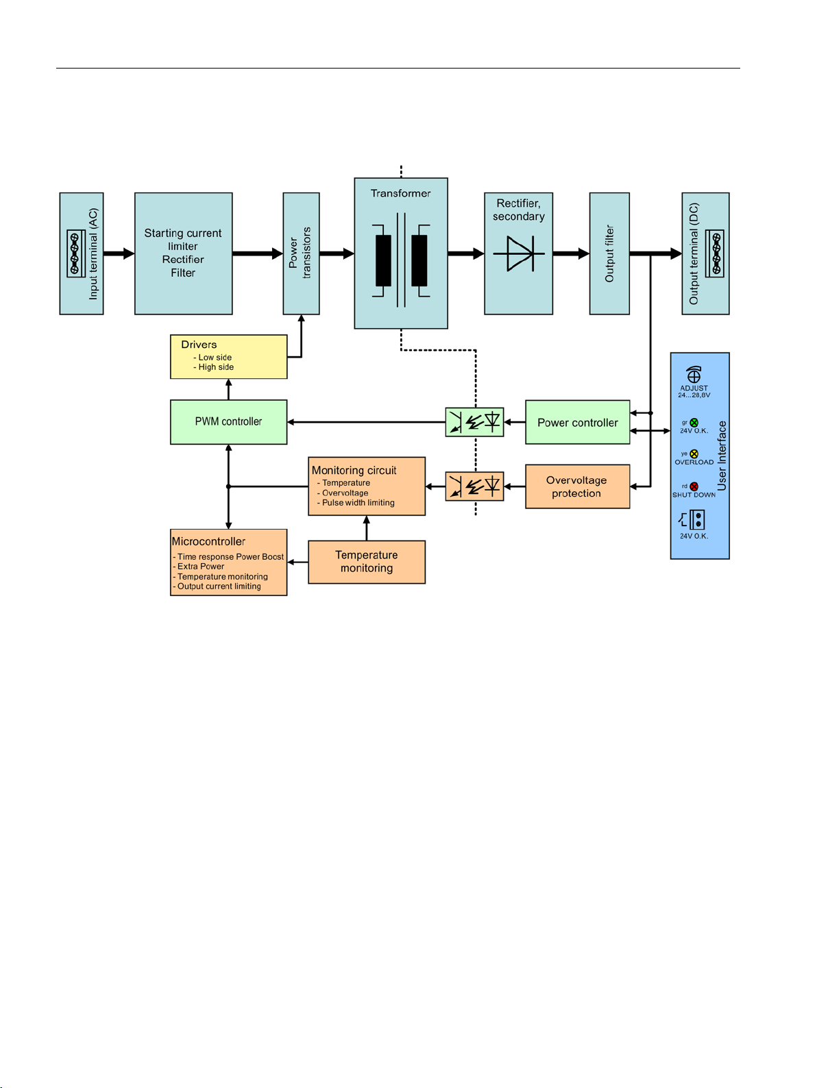
2.6
Block diagram
2.6 Block diagram
Figure 2-7 Block diagram 6EP3436-8SB00-0AY0 (PR1) and 6EP1437-3BA10
SITOP PSU8200/3800 3ph
20 Manual, 05.2018, C98130-A7638-A1-6-7629
Description, device design, dimension drawing
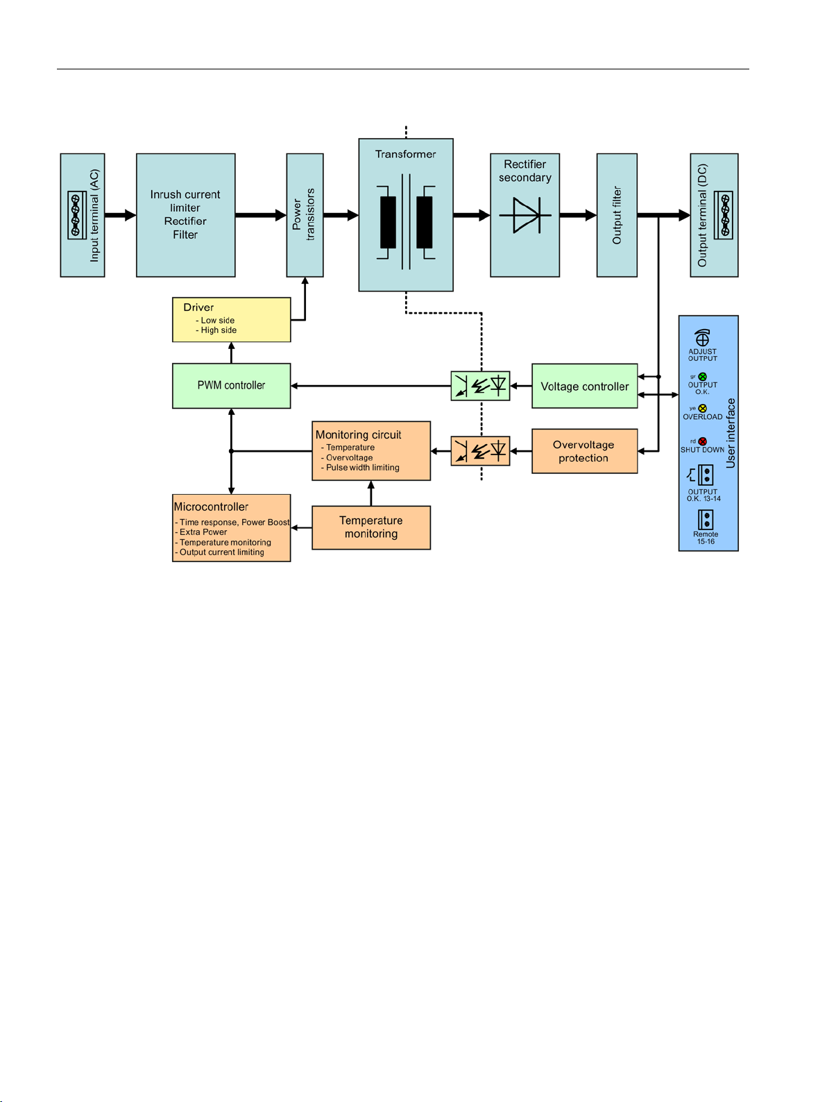
2.6 Block diagram
Figure 2-8 Block diagram 6EP3436-8SB00-0AY0 (from PR 2) 6EP3446-8SB10-0AY0, 6EP3446-8SB00-0AY0, 6EP3424-
8UB00-0AY0, and 6EP3436-8UB00-0AY0
SITOP PSU8200/3800 3ph
Manual, 05.2018, C98130-A7638-A1-6-7629
21
Description, device design, dimension drawing
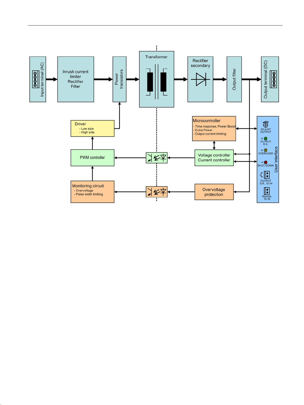
2.6 Block diagram
Figure 2-9 Block diagram for 6EP3437-8SB00-0AY0, 6EP3437-8UB00-0AY0 and 6EP3447-8SB00-0AY0
SITOP PSU8200/3800 3ph
22 Manual, 05.2018, C98130-A7638-A1-6-7629
Description, device design, dimension drawing
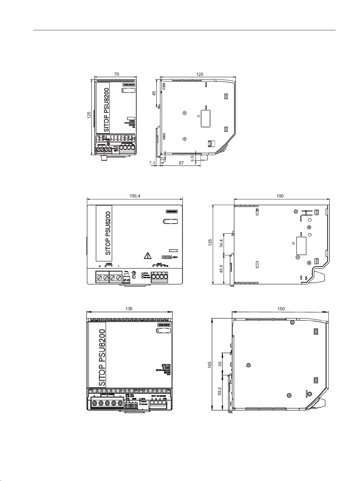
2.7
Dimensions and weight
2.7 Dimensions and weight
Figure 2-10 Dimension drawing 6EP3436-8SB00-0AY0, 6EP3446-8SB10-0AY0, 6EP3446-8SB00-
0AY0, 6EP3424-8UB00-0AY0 and 6EP3436-8UB00-0AY0
Figure 2-11 Dimension drawing 6EP1437-3BA10
Figure 2-12 Dimension drawing 6EP3437-8SB00-0AY0, 6EP3447-8SB00-0AY0 and 6EP3437-
8UB00-0AY0
SITOP PSU8200/3800 3ph
Manual, 05.2018, C98130-A7638-A1-6-7629
23

Description, device design, dimension drawing
6EP3436-8SB00-0AY0
(24 V/20 A)
6EP3446-8SB10-0AY0
(36 V/13 A)
6EP3446-8SB00-0AY0
(48 V/10 A)
6EP3424-8UB00-0AY0
(12 V/20 A)
6EP3436-8UB00-0AY0
(24 V/17 A)
6EP1437-3BA10
(24 V/40 A)
6EP3437-8SB00-0AY0
(24 V/40 A)
6EP3447-8SB00-0AY0
(48 V/20 A)
6EP3437-8UB00-0AY0
(24 V/40 A)
mm
Weight
approx. 1.2 kg
approx. 3.4 kg
approx. 3.3 kg
2.7 Dimensions and weight
Dimensions (W × H × D) in
70 × 125 × 125 150 × 125 × 150 135 × 145 × 150
SITOP PSU8200/3800 3ph
24 Manual, 05.2018, C98130-A7638-A1-6-7629
3
WARNING
Installing the device in a housing or a control cabinet
Mounting
Removal
The SITOP PSU8200/3800 3ph power supply is a built-in device. It must be installed in a
housing or control cabinet, to which only qualified personnel have access.
The device can be mounted in a control cabinet on standard mounting rails (see Chapter
Mechanical system (Page 80))
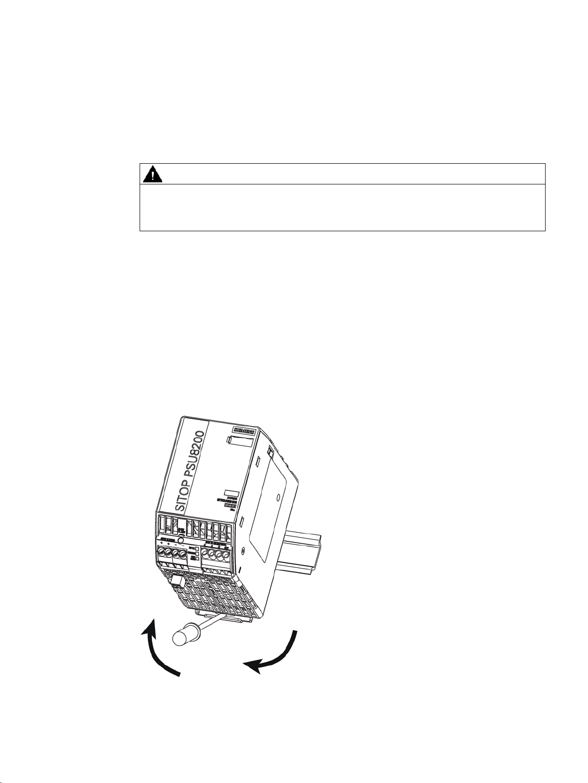
To mount the device, position it with the mounting rail guide at the upper edge of the
standard mounting rail and press down to lock it into place. If it is too difficult to snap them
into place, press slider at the same time, as described under "Removal".
To remove, pull up the slider using a screwdriver and disengage the device at the bottom
edge of the standard mounting rail. Then you can remove the device from the upper edge of
the standard mounting rail.
Figure 3-1 Mounting/removal (example 6EP3436-8SB00-0AY0)
SITOP PSU8200/3800 3ph
Manual, 05.2018, C98130-A7638-A1-6-7629
25

Mounting/removing
WARNING
Use in hazardous zones
If the devices are to be used in hazardous zones (Ex II 3G Ex nA nC IIC T4 Gc) they must
be installed in a distribution box with degree of protection IP54 or higher.
SITOP PSU8200/3800 3ph
26 Manual, 05.2018, C98130-A7638-A1-6-7629
4
4.1
Standard mounting position
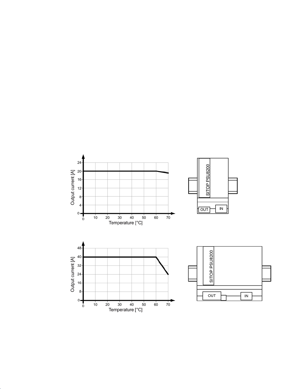
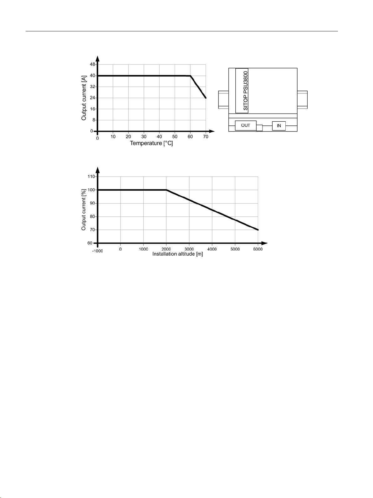
Output current as a function of the ambient temperature and mounting height
The device is mounted on standard mounting rails. The device must be mounted vertically in
such a way that the input terminals and the output terminals are at the bottom to ensure
correct cooling.
A clearance of at least 40 mm or 50 mm should be maintained above and below the device
(maximum depth of the cable duct, 50 mm).
No space is required at the side.
Figure 4-1 6EP3436-8SB00-0AY0: Output current in the standard mounting position
Figure 4-2 6EP1437-3BA10: Output current in the standard mounting position
SITOP PSU8200/3800 3ph
Manual, 05.2018, C98130-A7638-A1-6-7629
27
Mounting position, mounting clearances
4.1 Standard mounting position
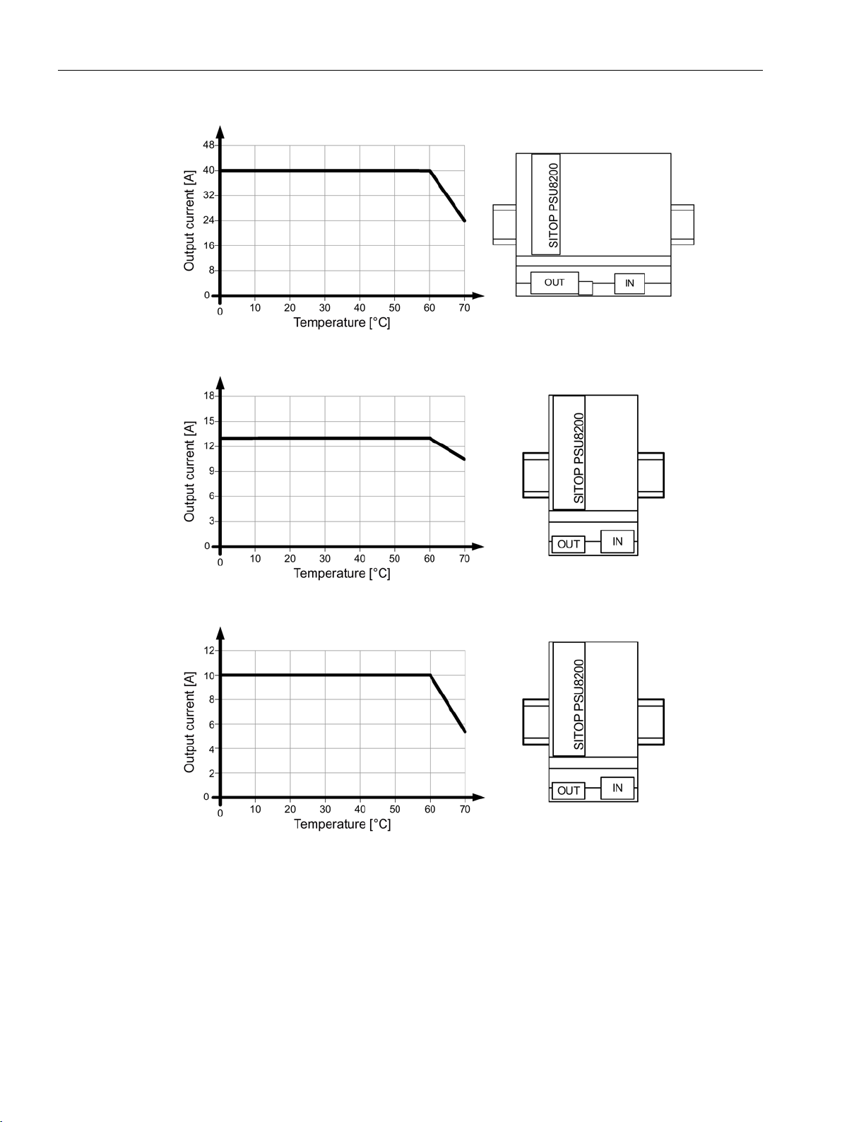
Figure 4-3 6EP3437-8SB00-0AY0: Output current in the standard mounting position
Figure 4-4 6EP3446-8SB10-0AY0: Output current in the standard mounting position
Figure 4-5 6EP3446-8SB00-0AY0: Output current in the standard mounting position
SITOP PSU8200/3800 3ph
28 Manual, 05.2018, C98130-A7638-A1-6-7629
Mounting position, mounting clearances
4.1 Standard mounting position
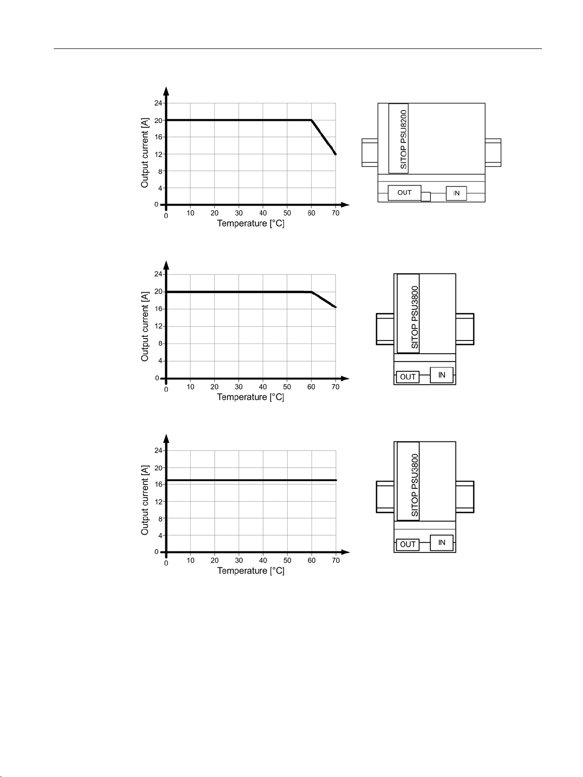
Figure 4-6 6EP3447-8SB00-0AY0: Output current in the standard mounting position
Figure 4-7 6EP3424-8UB00-0AY0: Output current in the standard mounting position
Figure 4-8 6EP3436-8UB00-0AY0: Output current in the standard mounting position
SITOP PSU8200/3800 3ph
Manual, 05.2018, C98130-A7638-A1-6-7629
29
Mounting position, mounting clearances
4.1 Standard mounting position
Figure 4-9 6EP3437-8UB00-0AY0: Output current in the standard mounting position
Figure 4-10 Mounting height derating
For details, see Ambient conditions (Page 91)
SITOP PSU8200/3800 3ph
30 Manual, 05.2018, C98130-A7638-A1-6-7629
 Loading...