

Siemens SITOP PSU6200 User Manual

___________________
___________________
___________________
___________________
___________________
___________________
___________________
___________________
___________________
___________________
___________________
___________________
SITOP power supply
SITOP PSU6200 1ph
Manual
SITOP PSU6200 12 V/7 A
6EP3323
SITOP PSU6200 12 V/12 A
6EP3324
SITOP PSU6200 24 V/3.7 A
6EP3333
SITOP PSU6200 24 V/5 A
6EP3333
SITOP PSU6200 24 V
6EP3334
SITOP PSU6200 24 V/20 A
6EP3336
03.2019
A5E44623264
Overview
Notes on safety
1
Description, device design,
dimension drawing
2
Mounting/removal
3
Mounting position, mounting
clearances
4
Installation
5
Technical data
6
Safety, approvals, EMC
7
Ambient conditions
8
Applications
9
Environment
10
Service & Support
11
-7SB00-0AX0
-7SB00-3AX0
-7LB00-0AX0
-7SB00-0AX0
/10 A
-7SB00-3AX0
-7SB00-3AX0
-1-76
Siemens AG
Division Process Industries and Drives
Postfach 48 48
90026 NÜRNBERG
GERMANY
A5E44623264-1-76
Ⓟ
Copyright © Siemens AG 2019.
All rights reserved
DANGER
indicates that death or severe personal injury will result if proper precautions are not taken.
WARNING
indicates that death or severe personal injury may result if proper precautions are not taken.
CAUTION
indicates that minor personal injury can result if proper precautions are not taken.
NOTICE
indicates that property damage can result if proper precautions are not taken.
WARNING
Siemens products may only be used for the applications described in the catalog and in the relevant technical
ambient conditions must be complied with. The information in the relevant documentation must be observed.
Legal information
Warning notice system
This manual contains notices you have to observe in order to ensure your personal safety, as well as to prevent
damage to property. The notices referring to your personal safety are highlighted in the manual by a safety alert
symbol, notices referring only to property damage have no safety alert symbol. These notices shown below are
graded according to the degree of danger.
If more than one degree of danger is present, the warning notice representing the highest degree of danger will
be used. A notice warning of injury to persons with a safety alert symbol may also include a warning relating to
property damage.
Qualified Personnel
The product/system described in this documentation may be operated only by personnel qualified for the specific
task in accordance with the relevant documentation, in particular its warning notices and safety instructions.
Qualified personnel are those who, based on their training and experience, are capable of identifying risks and
avoiding potential hazards when working with these products/systems.
Proper use of Siemens products
Note the following:
documentation. If products and components from other manufacturers are used, these must be recommended
or approved by Siemens. Proper transport, storage, installation, assembly, commissioning, operation and
maintenance are required to ensure that the products operate safely and without any problems. The permissible
Trademarks
All names identified by ® are registered trademarks of Siemens AG. The remaining trademarks in this publication
may be trademarks whose use by third parties for their own purposes could violate the rights of the owner.
Disclaimer of Liability
We have reviewed the contents of this publication to ensure consistency with the hardware and software
described. Since variance cannot be precluded entirely, we cannot guarantee full consistency. However, the
information in this publication is reviewed regularly and any necessary corrections are included in subsequent
editions.
03/2019 Subject to change
Overview
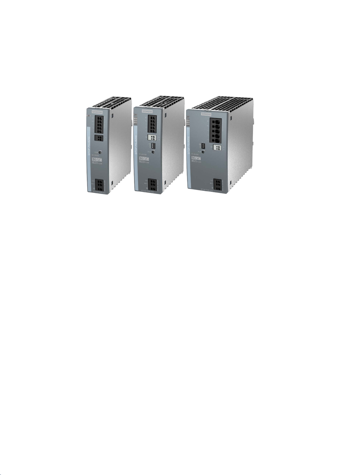
Figure 1 View of devices
The 1-phase SITOP PSU6200 from the product line is a powerful, regulated standard power
supply for automated machines and systems. In addition to a high efficiency, these lowprofile power supply units have an outstanding overload behavior.
The key benefits of the product include:
● Wide-range input that allows it to be connected to almost any 1-phase line supply around
the world – or to a DC power source
● The output voltage can be set in the range 12 V - 15.5 V or 24 V - 28 V
● Brief overload capability of 150% for 5 s/min (extra power)
● Continuous overload capability of 120% up to an ambient temperature of 45 °C
● Integrated signaling contact for "12 V O.K." or "24 V O.K."
● Push-in connections facilitate fast wiring
● Diagnostic monitor with utilization and service life display using LEDs
● Diagnostics interface to connect to the automation system via only one digital PLC input
● Ambient temperature -25 °C ... 70 °C
● To increase the system availability, these reliable power supplies can be expanded using
SITOP supplementary modules (redundancy module, selectivity module, buffer module),
as well as SITOP DC-UPS modules.
SITOP PSU6200 1ph
Manual, 03.2019, A5E44623264-1-76
3
Overview
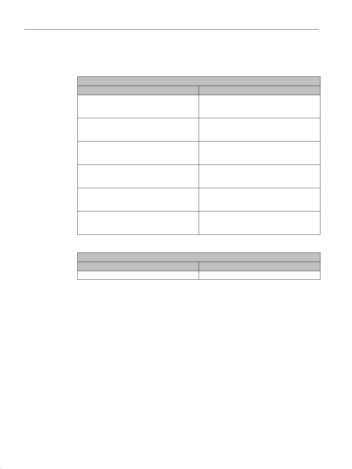
Regulated SITOP PSU6200S power supply
Type
Order number
Output 12 V DC/7 A
Output 12 V DC/12 A
Output 24 V DC/3.7 A
Output 24 V DC/5 A
24 V/10 A DC output
24 V/20 A DC output
Accessories
Type
Order number
Reference labeling plate (160 plates)
6ES7193-6LF30-0AW0
Ordering data
The following device options are available:
Input 1 AC 120/230 V,
110 - 240 V DC
Input 1 AC 120/230 V,
110 - 240 V DC
Input 1 AC 120/230 V,
120 - 240 V DC
Input 1 AC 120/230 V,
120 - 240 V DC
Input 1 AC 120/230 V,
120 - 240 V DC
Input 1 AC 120/230 V,
120 - 240 V DC
6EP3323-7SB00-0AX0
6EP3324-7SB00-3AX0
6EP3333-7LB00-0AX0
6EP3333-7SB00-0AX0
6EP3334-7SB00-3AX0
6EP3336-7SB00-3AX0
SITOP PSU6200 1ph
4 Manual, 03.2019, A5E44623264-1-76

Table of contents
Overview .................................................................................................................................................... 3
1 Notes on safety .......................................................................................................................................... 7
2 Description, device design, dimension drawing ......................................................................................... 9
2.1 Device description ..................................................................................................................... 9
2.2 Connections and terminal designation.................................................................................... 10
2.3 Potentiometer .......................................................................................................................... 11
2.4 Status displays and signaling ................................................................................................. 12
2.5 Operating mode ...................................................................................................................... 15
2.6 Block diagram ......................................................................................................................... 16
2.7 Dimensions and weight ........................................................................................................... 18
3 Mounting/removal .................................................................................................................................... 21
4 Mounting position, mounting clearances .................................................................................................. 23
4.1 Standard mounting position .................................................................................................... 23
4.2 Other mounting positions ........................................................................................................ 26
4.2.1 6EP3323-7SB00-0AX0 ........................................................................................................... 26
4.2.2 6EP3324-7SB00-3AX0 ........................................................................................................... 28
4.2.3 6EP3333-7LB00-0AX0 ........................................................................................................... 30
4.2.4 6EP3333-7SB00-0AX0 ........................................................................................................... 32
4.2.5 6EP3334-7SB00-3AX0 ........................................................................................................... 34
4.2.6 6EP3336-7SB00-3AX0 ........................................................................................................... 36
5 Installation ............................................................................................................................................... 39
5.1 Line-side connection ............................................................................................................... 39
5.2 Output-side connection ........................................................................................................... 41
6 Technical data ......................................................................................................................................... 43
6.1 Input ........................................................................................................................................ 43
6.2 Output ..................................................................................................................................... 46
6.3 Efficiency ................................................................................................................................. 52
6.4 Closed-loop control ................................................................................................................. 56
6.5 Protection and monitoring ....................................................................................................... 57
6.6 MTBF ...................................................................................................................................... 58
6.7 Mechanical system ................................................................................................................. 59
6.8 Dimension drawing ................................................................................................................. 60
SITOP PSU6200 1ph
Manual, 03.2019, A5E44623264-1-76
5

Table of contents
7 Safety, approvals, EMC ........................................................................................................................... 61
7.1 Safety ..................................................................................................................................... 61
7.2 Test voltage ............................................................................................................................ 62
7.3 Approvals ............................................................................................................................... 63
7.4 EMC ....................................................................................................................................... 64
8 Ambient conditions .................................................................................................................................. 65
9 Applications ............................................................................................................................................. 67
9.1 Parallel connection to increase the power rating ................................................................... 67
9.2 Overload protection in the 24 V output circuit ........................................................................ 69
9.3 Protection against short-time voltage dips ............................................................................. 70
9.4 Protecting against longer power failures ................................................................................ 71
10 Environment ............................................................................................................................................ 73
11 Service & Support .................................................................................................................................... 75
SITOP PSU6200 1ph
6 Manual, 03.2019, A5E44623264-1-76

1
WARNING
Correct handling of the devices
When operating electrical devices, it is inevitable that certain components will carry
dangerous voltages.
Therefore, failure to handle the units properly can result in death or serious physical injury
as well as extensive property damage.
Only appropriately qualified personnel may work on or in the vicinity of this equipment.
Perfect, safe, and reliable operation of this equipment is dependent on proper
transportation, storage, installation and mounting.
Before installation or maintenance work can begin, the system's main switch must be
switched off and measures taken to prevent it being switched on again.
If this instruction is not observed, touching live parts can result in death or serious injury.
SITOP PSU6200 1ph
Manual, 03.2019, A5E44623264-1-76
7

Notes on safety
SITOP PSU6200 1ph
8 Manual, 03.2019, A5E44623264-1-76
2
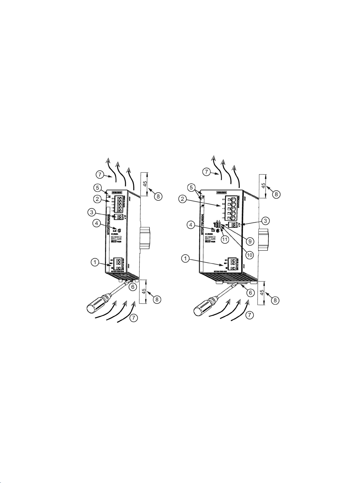
①
AC/DC input
②
DC output
③
Signaling contact (13, 14)
④
Potentiometer, 12 V - 15.5 V or 24 V - 28 V
⑤
Indicator light, diagnostics monitor (O.K., LOAD)
⑥
DIN rail slider
⑦
Convection
⑧
Clearance above/below
⑨
Diagnostics interface (COM)
⑩
DC voltage level increase (HV)
⑪
Parallel operation (PO)
2.1 Device description
SITOP PSU6200 is a primary-clocked power supply for connection to a 1-phase AC line
supply and a DC supply. An electronically regulated DC voltage that can be set via a
potentiometer is available at the output of the device. The output of the device is isolated,
no-load proof and short-circuit proof. The LED display indicates the operating status. The
operating state of the device can be processed via the signaling contact.
Figure 2-1 Design
SITOP PSU6200 1ph
Manual, 03.2019, A5E44623264-1-76
9
Description, device design, dimension drawing
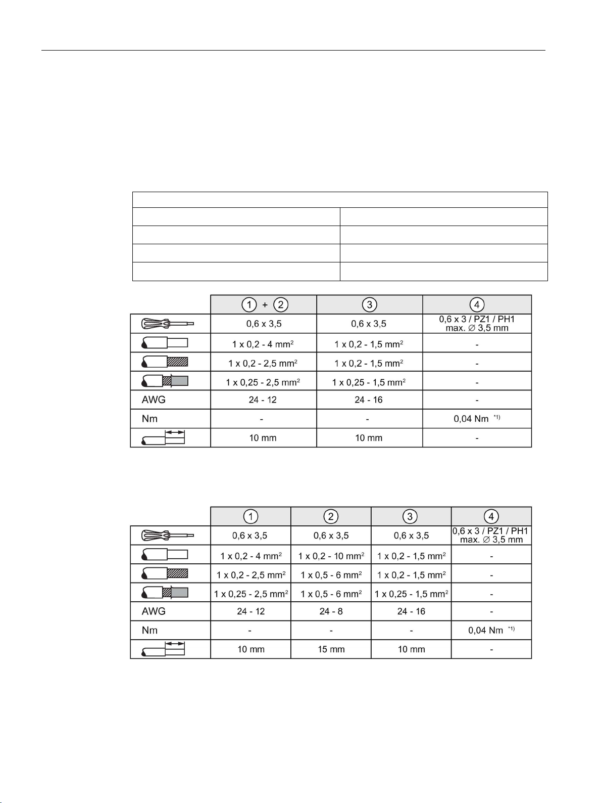
Connections and terminal designations
①
②
②
③
Do not subject the end stop to higher loads
Do not subject the end stop to higher loads
2.2 Connections and terminal designation
2.2 Connections and terminal designation
The line input terminals ① can be used to establish the connection to supply voltage. The
output terminals
Installation (Page 39)).
② are used to connect to the loads to be supplied (see also Section
The operating state of the device can be processed via the signaling contact
and contact rating, see Chapter Status displays and signaling (Page 12)).
Line input L1, N (L2), PE
Output +
Output –
Signaling contact 13, 14
*1)
one spring-loaded terminal each
2 spring-loaded terminals
3 spring-loaded terminals
one spring-loaded terminal each
③ (function
Figure 2-2 Terminal data for 6EP3323-7SB00-0AX0, 6EP3324-7SB00-3AX0, 6EP3333-7LB00-
0AX0, 6EP3333-7SB00-0AX0 and 6EP3334-7SB00-3AX0
*1)
Figure 2-3 Terminal data for 6EP3336-7SB00-3AX0
SITOP PSU6200 1ph
10 Manual, 03.2019, A5E44623264-1-76
Description, device design, dimension drawing
Type
Factory setting
Adjustment range
6EP3324-7SB00-3AX0
6EP3336-7SB00-3AX0
NOTICE
Thermal overload possible
Note
It is only permissible to use an insulated screwdriver when actuating the potentiometer.
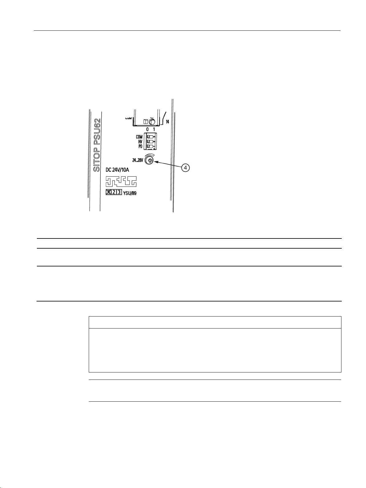
2.3 Potentiometer
2.3 Potentiometer
The potentiometer ④ on the front of the device is used to adjust the output voltage. The
output voltage is set to the rated value at the factory and can be set within certain limits; for
example, to compensate voltage drops across long supply lines to the connected load.
6EP3323-7SB00-0AX0
6EP3333-7LB00-0AX0
6EP3333-7SB00-0AX0
6EP3334-7SB00-3AX0
Figure 2-4 Potentiometer
12 V 12 V - 15.5 V
24 V 24 V - 28 V
When adjusting the output voltage to greater than the rated voltage, the output current must
be derated by 4 %/V (for devices with a rated output voltage of 24 V) and 8 %/V (for
devices with a rated output voltage of 12 V) – or the permissible ambient temperature must
be taken into account with 3 °C/V.
For information on actuating the potentiometer (screwdriver, torque), see Connections and
terminal designation (Page 10).
SITOP PSU6200 1ph
Manual, 03.2019, A5E44623264-1-76
11
Description, device design, dimension drawing
6EP3323-7SB00-0AX0 (12 V/7 A), 6EP3324-7SB00-3AX0 (12 V/12 A),
6EP3333-7LB00-0AX0 (24 V/3,7 A), 6EP3333-7SB00-0AX0 (24 V/5 A),
6EP3334-7SB00-3AX0 (24 V/10 A), 6EP3336-7SB00-3AX0 (24 V/20 A)
Yellow LED
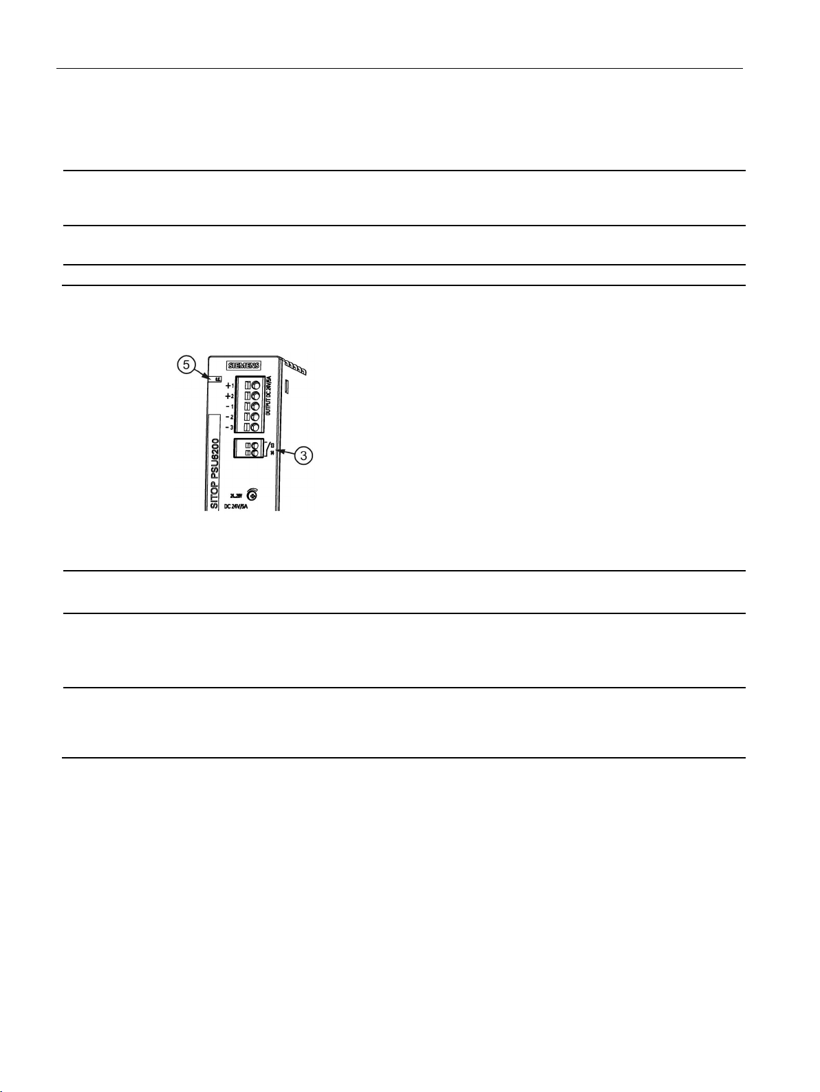
Signaling contact (13, 14)
Relay contact (NO contact, contact rating (isolated) 24 V AC/0.1 A; 30 V DC/0.1 A
Signaling
Signaling contact
6EP3323-7SB00-0AX0 (12 V/7 A)
6EP3333-7LB00-0AX0 (24 V/3.7 A)
6EP3333-7SB00-0AX0 (24 V/5 A)
LED "O.K.":
green flashing (0.5 Hz):
shutdown as a result of thermal overload
shutdown as a result of thermal overload
Signaling contact (13, 14)
NOTICE:
ing contact is connected on the primary side!
NOTICE:
ing contact is connected on the primary side!
2.4 Status displays and signaling
2.4 Status displays and signaling
Status display LED green for 12 V O.K. or 24 V O.K.
Device without diagnostics monitor
green:
closed:
Figure 2-5 Signaling, signaling contact
Output voltage U
U
> 11.8 V
out
Output voltage U
> 10 V or
out
> 10 V
out
contact rating: 24 V AC/0.1 A; 30 V DC/0.1 A
It is not permissible that the signal-
Output voltage U
U
> 23 V
out
Output voltage U
> 20 V or
out
> 20 V
out
contact rating 24 V AC/0.1 A; 30 V DC/0.1 A
It is not permissible that the signal-
SITOP PSU6200 1ph
12 Manual, 03.2019, A5E44623264-1-76
Description, device design, dimension drawing
Signaling contact
6EP3324-7SB00-3AX0 (12 V/12 A)
6EP3334-7SB00-3AX0 (24 V/10 A)
6EP3336-7SB00-3AX0 (24 V/20 A)
LED "O.K.":
green flashing (0.5 Hz):
shutdown as a result of thermal overload
shutdown as a result of thermal overload
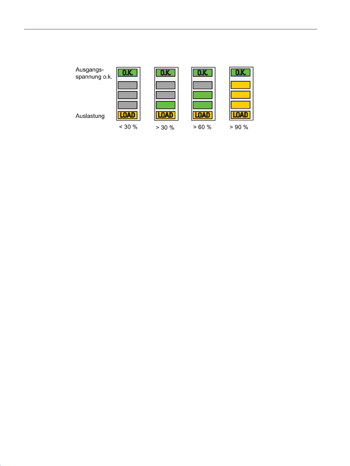
LED "LOAD":
yellow:
reached service life ≥ 90 %; I
out rated
≥ 90 %
reached service life ≥ 90 %; I
out rated
≥ 90 %
LEDs above LED "LOAD":
LEDs 5.1+5.2+5.3 yellow:
I
out rated
> 90 %
I
out rated
> 90 %
Contact ''COM'' (13, 14):
NOTICE:
tact is connected on the primary side!
NOTICE:
tact is connected on the primary side!
2.4 Status displays and signaling
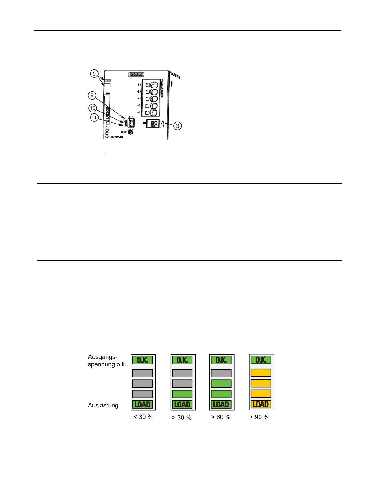
Device with diagnostics monitor
Figure 2-6 Signaling, signaling contact
green:
green:
LED 5.1 green:
LEDs 5.1+5.2 green:
closed:
(for DIP switch COM = 0)
Diagnostic monitor display:
Output voltage U
U
> 11.8 V
out
reached service life < 90 %
I
30 - 60 %
out rated
I
60 - 90 %
out rated
Output voltage U
or U
> 11.8 V; data transfer contact rating
out
24 V AC/0.1 A; 30 V DC/0.1 A
It is not permissible that the con-
> 10 V or
out
> 10 V
out
Output voltage U
U
> 23 V
out
> 20 V or
out
reached service life < 90 %
I
30 - 60 %
out rated
I
60 - 90 %
out rated
Output voltage U
or U
> 23 V; data transfer contact rating
out
> 20 V
out
24 V AC/0.1 A; 30 V DC/0.1 A
It is not permissible that the con-
SITOP PSU6200 1ph
Manual, 03.2019, A5E44623264-1-76
13
Description, device design, dimension drawing
2.4 Status displays and signaling
Service life < 10 %
SITOP PSU6200 1ph
14 Manual, 03.2019, A5E44623264-1-76
Description, device design, dimension drawing
DIP switch
6EP3324-7SB00-3AX0 (12 V/12 A)
6EP3334-7SB00-3AX0 (24 V/10 A)
6EP3336-7SB00-3AX0 (24 V/20 A)
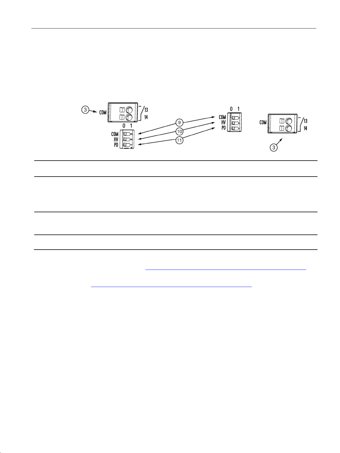
COM ⑨:
CAUTION:
Contact rating: 24 V AC/0.1 A; 30 V DC/0.1 A
HV ⑩:
1: > 11.8 V
PO ⑪:
pendent output voltage "parallel operation"
2.5 Operating mode
2.5 Operating mode
The selection is made using individual DIP switches (when supplied, these are in the 0
position).
It is only permissible to connect two identical devices in parallel to increase the power by
changing over the output characteristic by switching selector switch PO
⑪ to 1
Selector switch to toggle between the U
0: Display of the output voltage status
1: Internal device parameters are transferred via signaling contact (13, 14) (diagnostics interface)
It is not permissible that the signaling contact is connected on the primary side!
Setting, above which value, the "O.K." LED is lit.
0: > 10 V
Switching over output characteristic 0: Constant output voltage "single operation" 1: Load-de-
status display and the communication
out
Setting, above which the "O.K." LED is lit
0: > 20 V
1: > 23 V
Additional information can be found in the documents:
● Diagnostics interface (https://support.industry.siemens.com/cs/ww/en/view/109763467)
● Faceplates and communication blocks
(https://support.industry.siemens.com/cs/ww/en/view/109760217
)
SITOP PSU6200 1ph
Manual, 03.2019, A5E44623264-1-76
15
Description, device design, dimension drawing
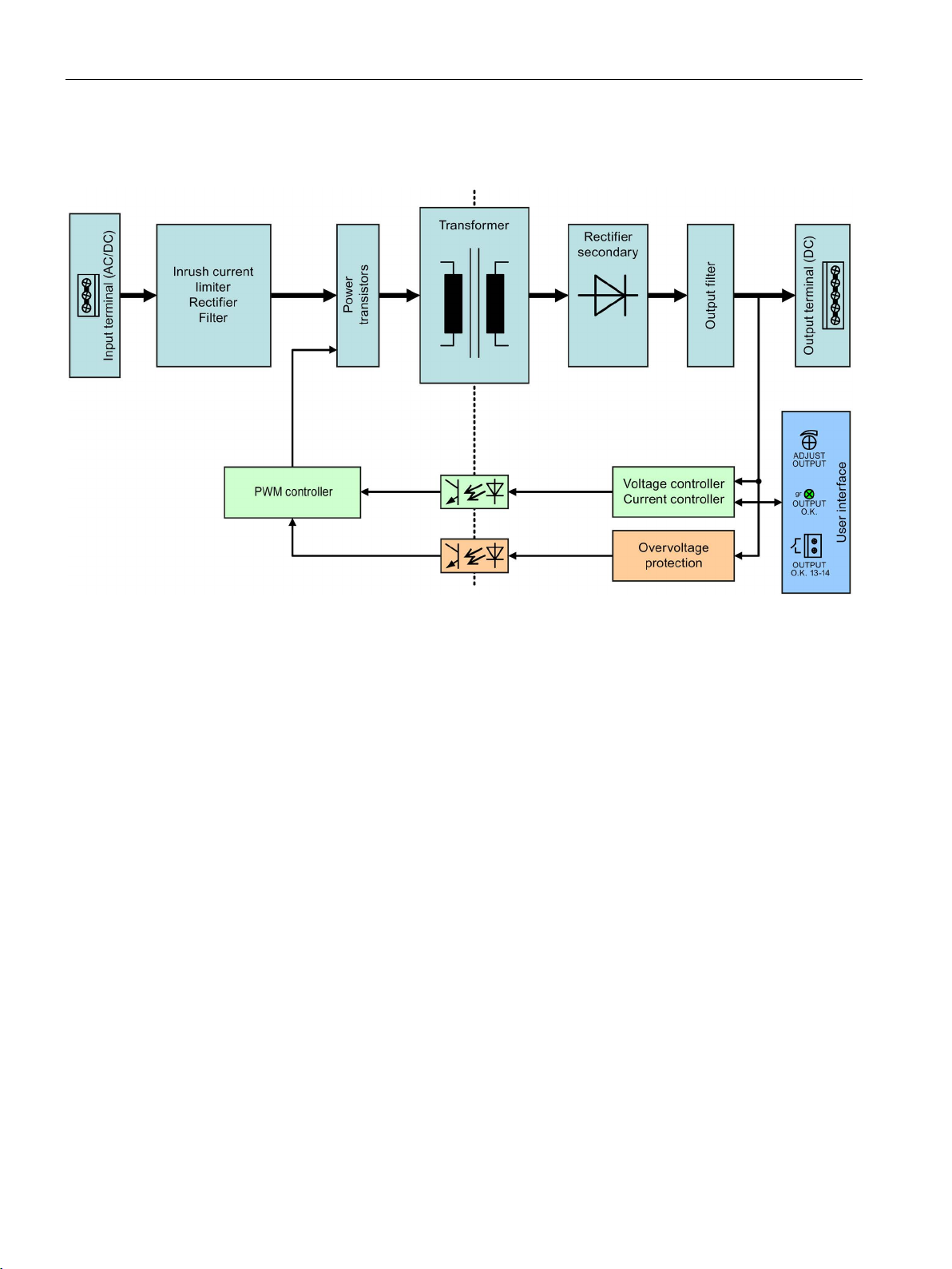
2.6 Block diagram
2.6 Block diagram
Figure 2-7 Block diagram 3.7/5/7 A
SITOP PSU6200 1ph
16 Manual, 03.2019, A5E44623264-1-76
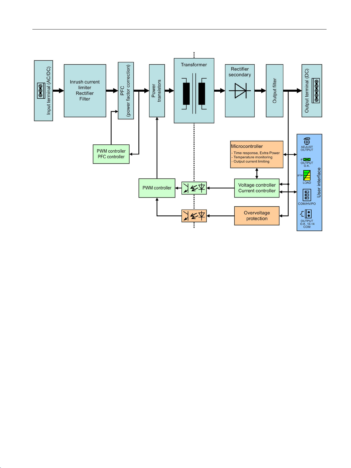
Description, device design, dimension drawing
2.6 Block diagram
Figure 2-8 Block diagram 10/12/20 A
SITOP PSU6200 1ph
Manual, 03.2019, A5E44623264-1-76
17
Description, device design, dimension drawing
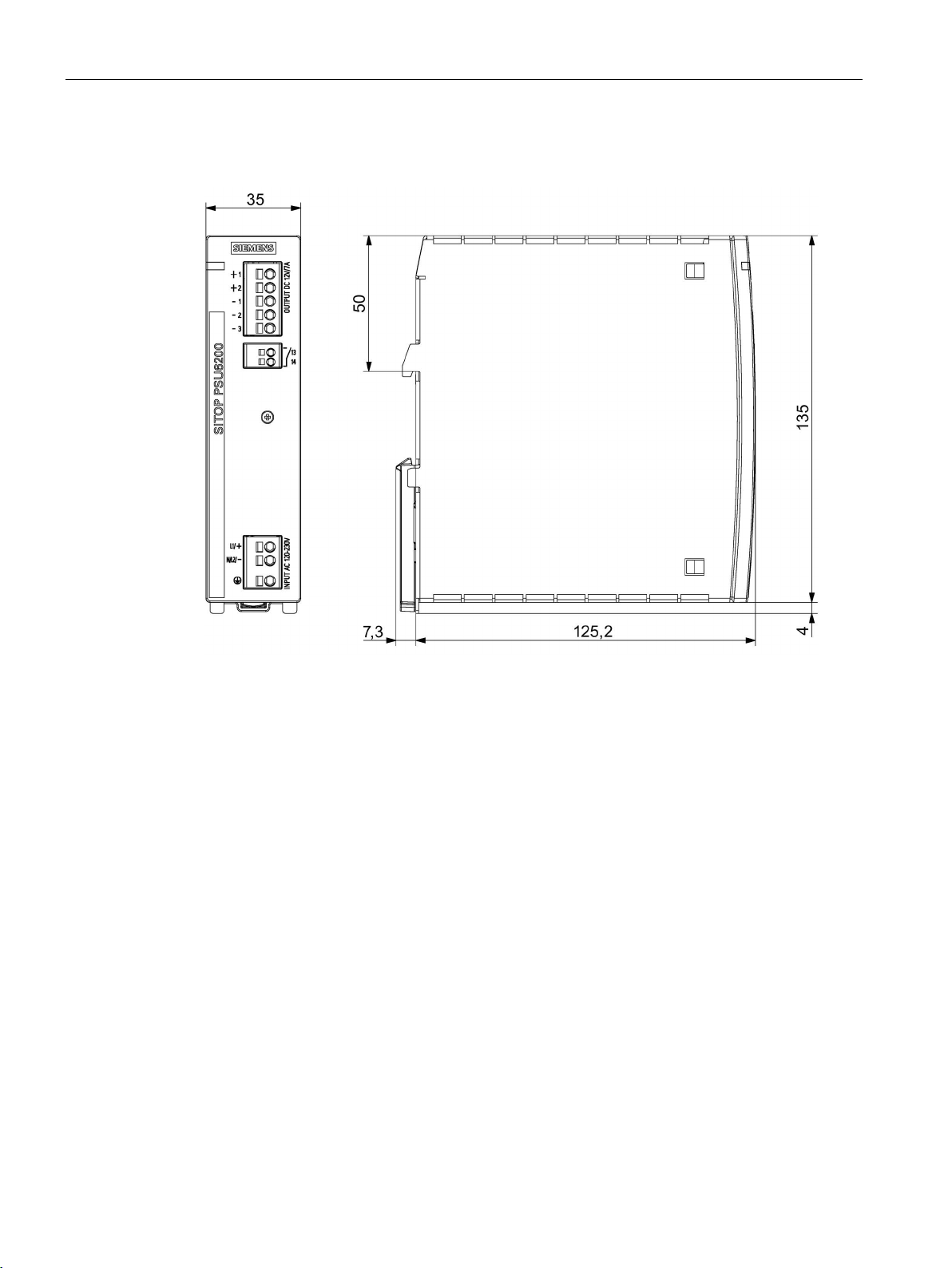
2.7 Dimensions and weight
2.7 Dimensions and weight
Figure 2-9 Dimension drawing
6EP3323-7SB00-0AX0
6EP3333-7LB00-0AX0
6EP3333-7SB00-0AX0
SITOP PSU6200 1ph
18 Manual, 03.2019, A5E44623264-1-76
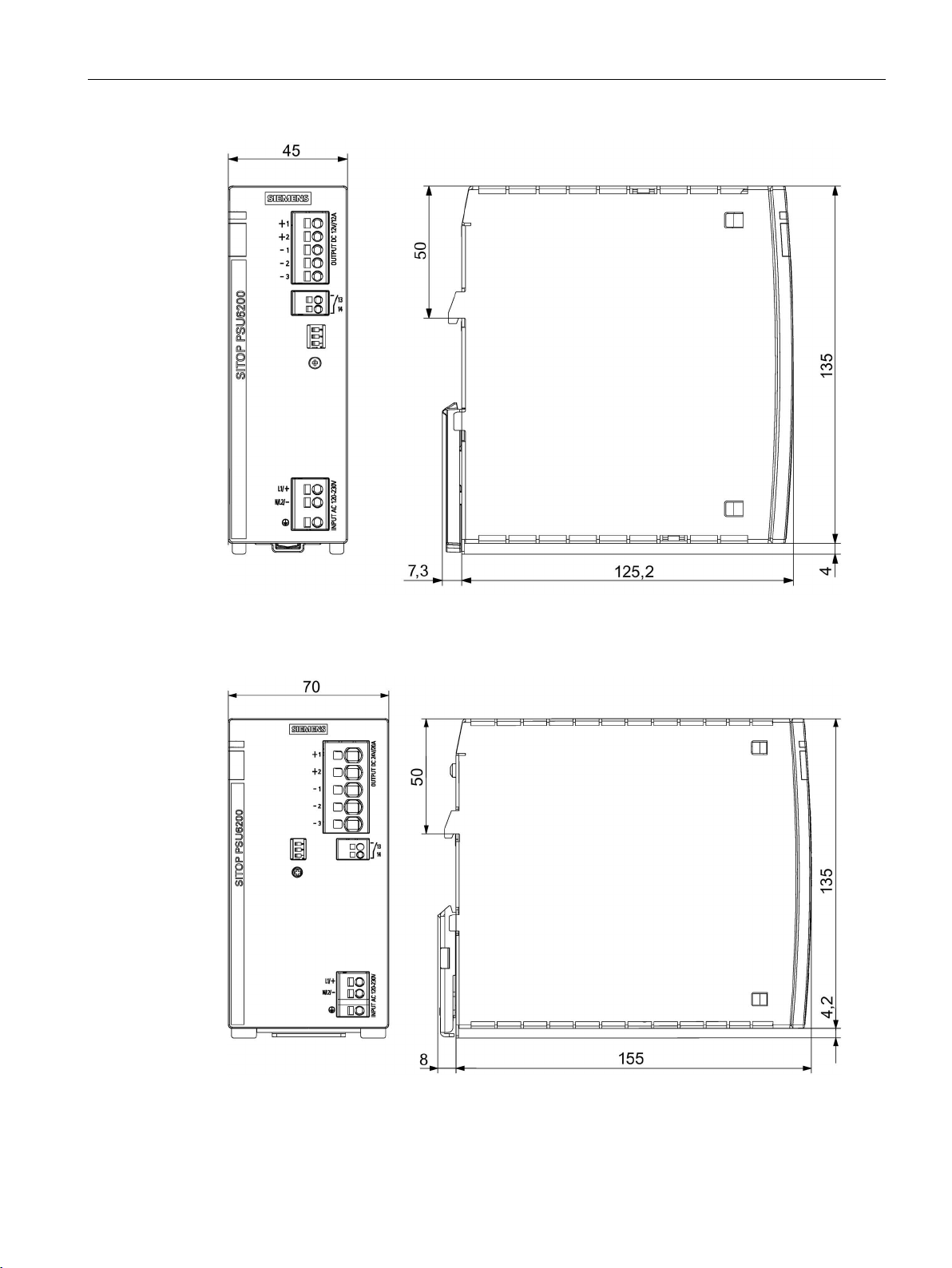
Description, device design, dimension drawing
2.7 Dimensions and weight
Figure 2-10 Dimension drawing
6EP3324-7SB00-3AX0
6EP3334-7SB00-3AX0
Figure 2-11 Dimension drawing 6EP3336-7SB00-3AX0
SITOP PSU6200 1ph
Manual, 03.2019, A5E44623264-1-76
19

Description, device design, dimension drawing
6EP3323-7SB00-0AX0
(12 V/7 A)
6EP3333-7LB00-0AX0
(24 V/3.7 A)
6EP3333-7SB00-0AX0
(24 V/5 A)
6EP3324-7SB00-3AX0
(12 V/12 A)
6EP3334-7SB00-3AX0
(24 V/10 A)
6EP3336-7SB00-3AX0
(24 V/20 A)
(W × H × D) in mm
Weight
Approx. 0.7 kg
Approx. 0.9 kg
Approx. 1.5 kg
2.7 Dimensions and weight
Dimensions
35 × 135 × 125 45 × 135 × 125 70 × 135 × 155
SITOP PSU6200 1ph
20 Manual, 03.2019, A5E44623264-1-76
3
WARNING
Installing the device in a housing or a control cabinet
devices. They must be installed in a housing or
SITOP PSU6200 power supplies are built-in
control cabinet where only qualified personnel have access.
The device can be mounted in a control cabinet on standard mounting rails according to
TH35-15/7,5 (EN 60715).
Mounting
The device must be mounted in such a way that the input terminals are at the bottom and the
output terminals at the top. A clearance of at least 45 mm must be maintained above and
below the device (max. cable duct depth 50 mm).
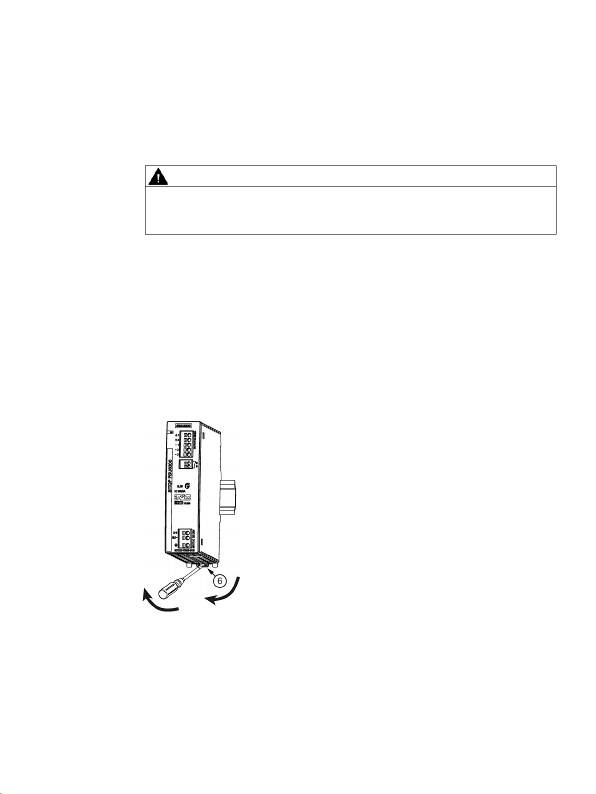
Removal
To remove, pull up the slider ⑥ using a screwdriver and disengage the device at the bottom
edge of the standard mounting rail (see Removal diagram). Then you can remove the device
from the upper edge of the standard mounting rail.
Figure 3-1 Mounting/removal
SITOP PSU6200 1ph
Manual, 03.2019, A5E44623264-1-76
21

Mounting/removal
SITOP PSU6200 1ph
22 Manual, 03.2019, A5E44623264-1-76
4
4.1 Standard mounting position
The device is mounted on standard mounting rails according to EN 60715 35x7,5/15. The
device must be mounted vertically in such a way that the input terminals are at the bottom
and the output terminals are at the top to ensure correct cooling.
A clearance of at least 45 mm must always be maintained above and below the device (max.
cable channel depth, 50 mm).
Lateral clearances do not have to be maintained.
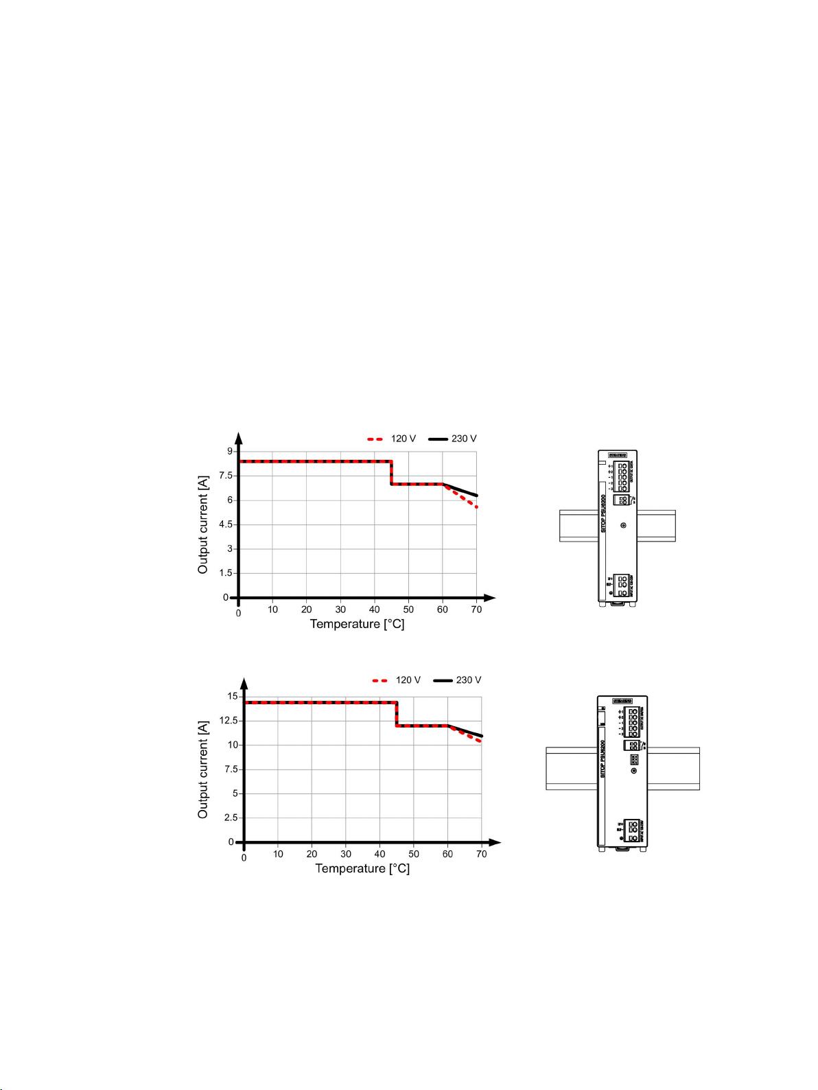
Output current as a function of the ambient temperature and mounting height
Figure 4-1 6EP3323-7SB00-0AX0 output current in the standard mounting position
Figure 4-2 6EP3324-7SB00-3AX0 output current in the standard mounting position
SITOP PSU6200 1ph
Manual, 03.2019, A5E44623264-1-76
23
 Loading...