

Siemens SITOP PSU400M User Manual

___________________
___________________
___________________
___________________
___________________
___________________
___________________
___________________
___________________
___________________
___________________
___________________
SITOP power supply
SITOP PSU400M
Manual
SITOP PSU400M 24 V/20 A
6EP1536
SITOP PSE400M
6EP1566
05.2018
C98130
Overview
Safety instructions
1
Description, device design,
dimension drawing
2
Mounting/removal
3
Mounting position, mounting
clearances
4
Installation
5
Technical data
6
Safety, approvals, EMC
7
Ambient conditions
8
Applications
9
Environment
10
Service & Support
11
-3AA00
-3AA00
-A7601-A1-5-7629
Siemens AG
Division Process Industries and Drives
Postfach 48 48
90026 NÜRNBERG
GERMANY
C98130-A7601-A1-5-7629
Ⓟ
Copyright © Siemens AG 2018.
All rights reserved
Legal information
Warning notice system
DANGER
indicates that death or severe personal injury will result if proper precautions are not taken.
WARNING
indicates that death or severe personal injury may result if proper precautions are not taken.
CAUTION
indicates that minor personal injury can result if proper precautions are not taken.
NOTICE
indicates that property damage can result if proper precautions are not taken.
Qualified Personnel
personnel qualified
Proper use of Siemens products
WARNING
Siemens products may only be used for the applications described in the catalog and in the relevant technical
ambient conditions must be complied with. The information in the relevant documentation must be observed.
Trademarks
Disclaimer of Liability
This manual contains notices you have to observe in order to ensure your personal safety, as well as to prevent
damage to property. The notices referring to your personal safety are highlighted in the manual by a safety alert
symbol, notices referring only to property damage have no safety alert symbol. These notices shown below are
graded according to the degree of danger.
If more than one degree of danger is present, the warning notice representing the highest degree of danger will
be used. A notice warning of injury to persons with a safety alert symbol may also include a warning relating to
property damage.
The product/system described in this documentation may be operated only by
task in accordance with the relevant documentation, in particular its warning notices and safety instructions.
Qualified personnel are those who, based on their training and experience, are capable of identifying risks and
avoiding potential hazards when working with these products/systems.
Note the following:
documentation. If products and components from other manufacturers are used, these must be recommended
or approved by Siemens. Proper transport, storage, installation, assembly, commissioning, operation and
maintenance are required to ensure that the products operate safely and without any problems. The permissible
All names identified by ® are registered trademarks of Siemens AG. The remaining trademarks in this publication
may be trademarks whose use by third parties for their own purposes could violate the rights of the owner.
We have reviewed the contents of this publication to ensure consistency with the hardware and software
described. Since variance cannot be precluded entirely, we cannot guarantee full consistency. However, the
information in this publication is reviewed regularly and any necessary corrections are included in subsequent
editions.
for the specific
05/2018 Subject to change
Overview
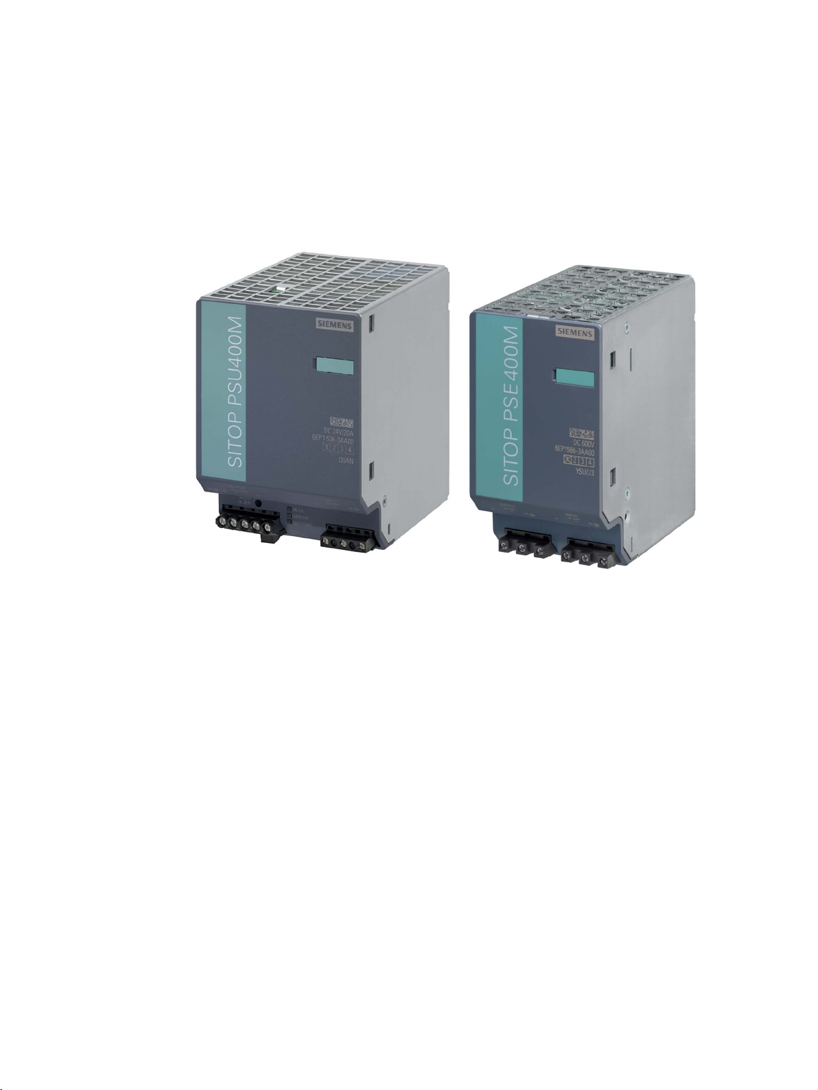
Description
Figure 1 View of devices
SITOP PSU400M is a power supply for DC link voltages of drive systems. If the power fails,
the energy of the flywheel mass and in the DC link capacitors is used to maintain the 24 V
supply for the electronics. As a consequence, axes can be stopped or retracted in a
controlled fashion. This can prevent expensive workpieces from being destroyed.
The key benefits of the product include:
● Rated input voltage 600 V DC
● Operating voltage range 200 (300) - 900 V DC
● High degree of efficiency up to 95 %
● Output voltage can be adjusted in the range 24 - 28.8 V
● Ambient temperature -25 ... 70 °C (derating from 60 °C)
● Brief overload capability of 150% for 5 s/min (extra power)
● No lateral mounting clearances are required
● Selectable short-circuit behavior
● Soft characteristic for parallel switching can be selected
● integrated signaling contact for "24 V O.K."
SITOP PSU400M
Manual, 05.2018, C98130-A7601-A1-5-7629
● Display of the operating state using 3 LEDs
3
Overview
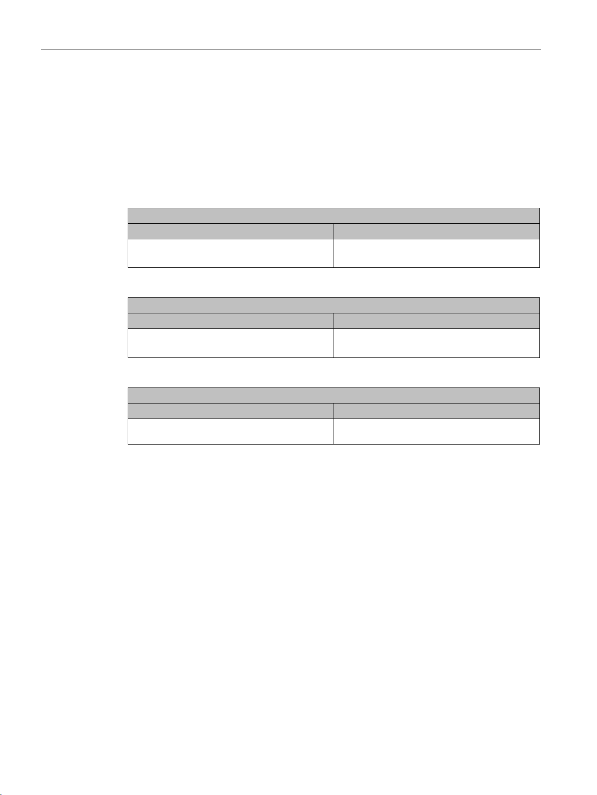
Ordering data
Regulated SITOP PSU400M power supply
Type
Order number
SITOP PSE400M voltage rise limiter
Type
Order number
Accessories
Type
Order number
turquoise
Validity
● Adjustable starting delay for operation on the DC link of SINAMICS converters
● Hot plug-in is possible when using the 6EP1566-3AA00 ballast as voltage rise limiter. A
filter is integrated in the ballast to improve the EMC of power supply PSU400M (only
applicable for product version 1).
The following device versions are available:
Input 600 V DC
Output 24 V DC / 20 A
6EP1536-3AA00
Input 600 V DC
Output 600 V DC
6EP1566-3AA00
Device identification labels 20 mm × 7 mm, pastel
3RT1900-1SB20
This manual provides information on the following products:
● SITOP PSU400M
Article No.: 6EP1536-3AA00
Product State: 2
Changes with respect to the previous version (PS 1):
– modified input voltage range and derating of the output current, see Figure 6-1 Derating
input range for product version 1 (Page 32), Figure 6-2 Derating input range for product
version 2 (Page 32)
● Voltage rise limiter SITOP PSE400M
Article No.: 6EP1566-3AA00
Product State: 2
Changes with respect to the previous version (PS 1):
– renamed from PSU400M to PSE400M
– no integrated EMC filter
SITOP PSU400M
4 Manual, 05.2018, C98130-A7601-A1-5-7629

Table of contents
Overview................................................................................................................................................. 3
1 Safety instructions ................................................................................................................................... 7
2 Description, device design, dimension drawing........................................................................................ 9
3 Mounting/removal ................................................................................................................................. 21
4 Mounting position, mounting clearances ................................................................................................ 23
5 Installation ............................................................................................................................................ 27
6 Technical data ...................................................................................................................................... 31
2.1 Device description ..................................................................................................................... 9
2.1.1 PSU400M .................................................................................................................................. 9
2.1.2 Voltage rise limiter .................................................................................................................. 10
2.2 Connections and terminal designation.................................................................................... 11
2.2.1 PSU400M ................................................................................................................................ 11
2.2.2 Voltage rise limiter .................................................................................................................. 12
2.3 Potentiometer .......................................................................................................................... 13
2.4 Operating displays and signaling ............................................................................................ 14
2.5 Selector switch ........................................................................................................................ 15
2.6 Block diagram ......................................................................................................................... 17
2.6.1 PSU400M ................................................................................................................................ 17
2.6.2 Voltage rise limiter .................................................................................................................. 18
2.7 Dimensions and weight ........................................................................................................... 19
4.1 Standard mounting position .................................................................................................... 23
4.2 Other mounting positions ........................................................................................................ 24
5.1 Line-side connection ............................................................................................................... 27
5.2 Output-side connection ........................................................................................................... 29
6.1 Input ........................................................................................................................................ 31
6.2 Output ..................................................................................................................................... 35
6.3 Efficiency ................................................................................................................................. 38
6.4 Closed-loop control ................................................................................................................. 38
6.5 Protection and monitoring ....................................................................................................... 39
6.6 MTBF ...................................................................................................................................... 39
6.7 Mechanical system ................................................................................................................. 39
6.8 Accessories ............................................................................................................................. 40
6.9 Dimension drawing ................................................................................................................. 40
SITOP PSU400M
Manual, 05.2018, C98130-A7601-A1-5-7629
5

Table of contents
7 Safety, approvals, EMC ........................................................................................................................ 41
8 Ambient conditions ................................................................................................................................ 45
9 Applications .......................................................................................................................................... 47
10 Environment ......................................................................................................................................... 55
11 Service & Support ................................................................................................................................. 57
7.1 Safety ..................................................................................................................................... 41
7.2 Test voltage ............................................................................................................................ 42
7.3 Approvals ............................................................................................................................... 43
7.4 EMC ....................................................................................................................................... 43
9.1 Parallel connection to increase the power rating ................................................................... 47
9.2 Parallel connection for redundancy ....................................................................................... 49
9.3 Series connection for increased voltage ................................................................................ 50
9.4 Overload protection in the 24 V output circuit ........................................................................ 51
9.5 Protection against longer failure of the power supply voltage ............................................... 52
SITOP PSU400M
6 Manual, 05.2018, C98130-A7601-A1-5-7629
1
WARNING
Correct handling of the devices
When operating electrical devices, it is inevitable that certain components will carry
dangerous voltages.
Therefore, failure to handle the units properly can result in death or serious physical injury
as well as extensive property damage.
Only appropriately qualified personnel may work on or in the vicinity of this equipment.
Perfect, safe, and reliable operation of this equipment is dependent on proper
transportation, storage, installation and mounting.
Before installation or maintenance work can begin, the system's main switch must be
switched off and measures taken to prevent it being switched on again.
If this instruction is not observed, touching live parts can result in death or serious injury.
SITOP PSU400M
Manual, 05.2018, C98130-A7601-A1-5-7629
7

Safety instructions
SITOP PSU400M
8 Manual, 05.2018, C98130-A7601-A1-5-7629
2
2.1
Device description
2.1.1
PSU400M
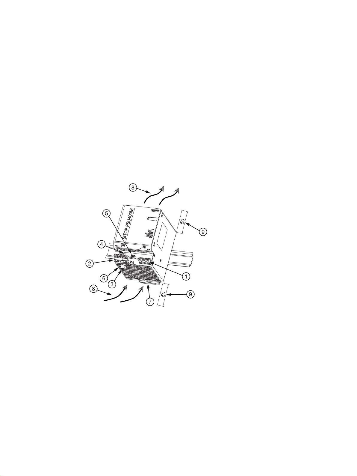
①
DC input
②
DC output
③
Signaling contact
④
24 - 28.8 V potentiometer
⑤
Indicator lights (24 V O.K., OVERLOAD, SHUTDOWN)
⑥
A/B/C selector switch
⑦
DIN rail slider
⑧
Natural convection
⑨
Clearance above/below
SITOP PSU400M is a primary-clocked power supply for connection to DC supply voltages
(e.g. to the DC link voltage of drive systems). An electronically regulated DC voltage that can
be set via a potentiometer is available at the output of the device. The output of the device is
isolated, no-load proof and short-circuit proof. The LED display indicates the operating
status. The operating state of the device can be processed via the signaling contact.
Figure 2-1 6EP1536-3AA00 design
SITOP PSU400M
Manual, 05.2018, C98130-A7601-A1-5-7629
9
Description, device design, dimension drawing
2.1.2
Voltage rise limiter
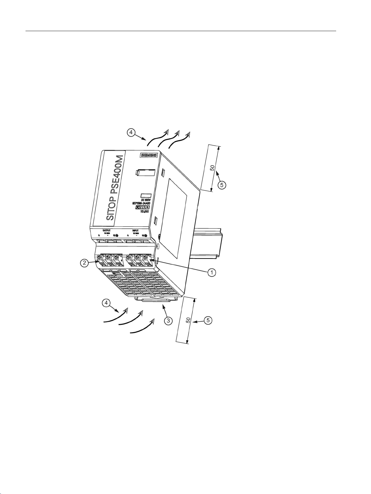
①
DC input
②
DC output
③
DIN rail slider
④
Convection
⑤
Clearance above/below
2.1 Device description
The 6EP1566-3AA00 voltage rise limiter is used as ballast for the PSU400M 24 V/20 A
power supply.
A filter is integrated in the ballast to improve the EMC of power supply PSU400M (only
applicable for product version 1).
It is not permissible that a 6EP1566-3AA00 ballast device is connected in parallel or in series
with a second ballast device.
SITOP PSU400M
10 Manual, 05.2018, C98130-A7601-A1-5-7629
Figure 2-2 6EP1566-3AA00 design
Description, device design, dimension drawing
2.2
Connections and terminal designation
2.2.1
PSU400M
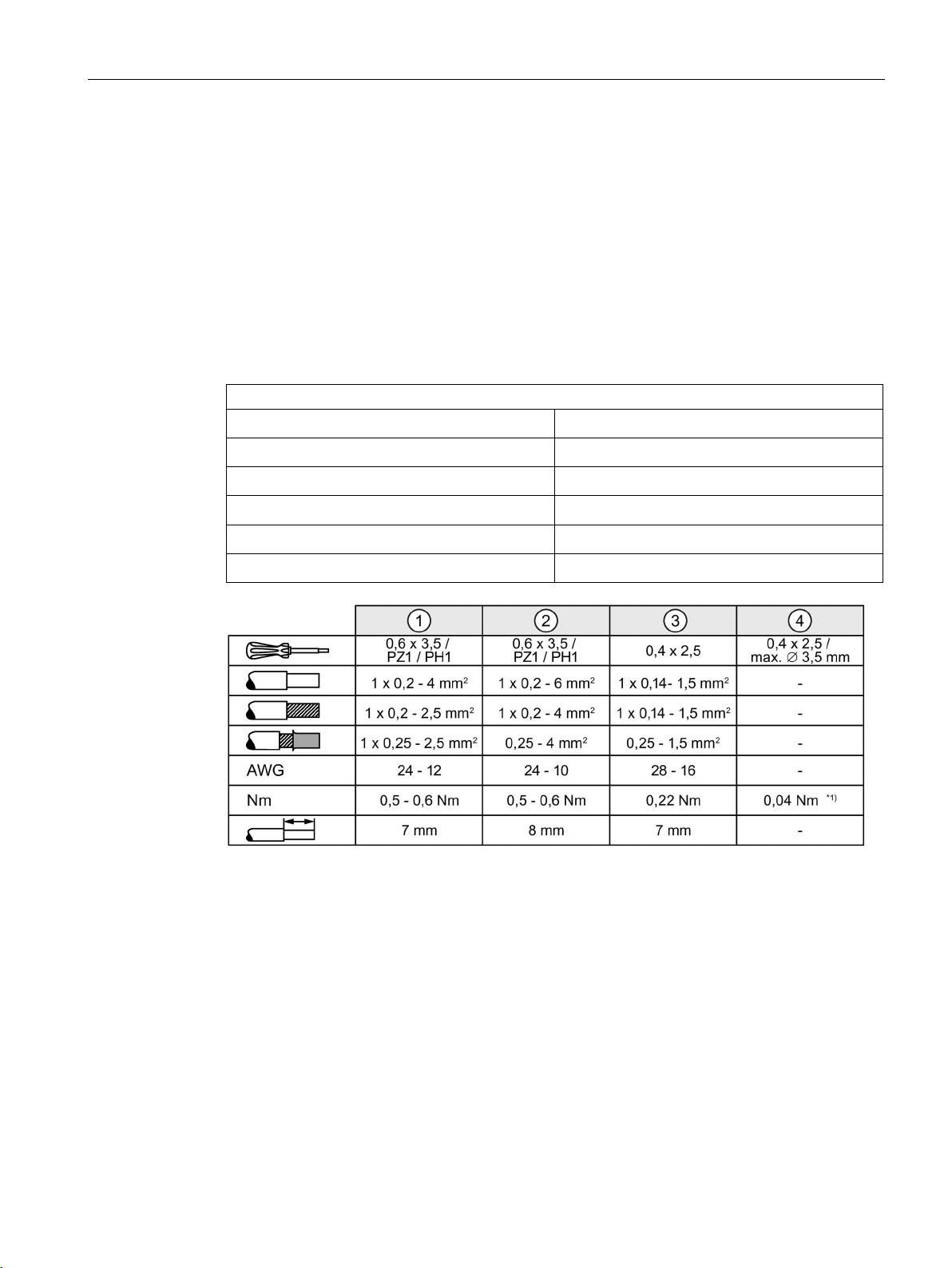
Connections and terminal designations 6EP1536-3AA00
①
①
②
②
②
③
Do not subject the end stop to higher loads
2.2 Connections and terminal designation
The input terminals ① can be used to establish the connection to the supply voltage. Output
terminals
(Page 27)).
② are used to connect to the loads to be supplied (see Section Installation
The operating state of the device can be processed via the signaling contact
and contact rating, see Chapter Operating displays and signaling (Page 14)).
Line input 600 V DC: "+", "-"
Line input PE
output "+"
output "–"
Output PE
signaling contacts 13, 14
One screw terminal each
1 screw terminal
2 screw terminals
2 screw terminals
1 screw terminal
One screw terminal each
③ (function
*1)
Figure 2-3 Terminal data for 6EP1536-3AA00
SITOP PSU400M
Manual, 05.2018, C98130-A7601-A1-5-7629
11
Description, device design, dimension drawing
2.2.2
Voltage rise limiter
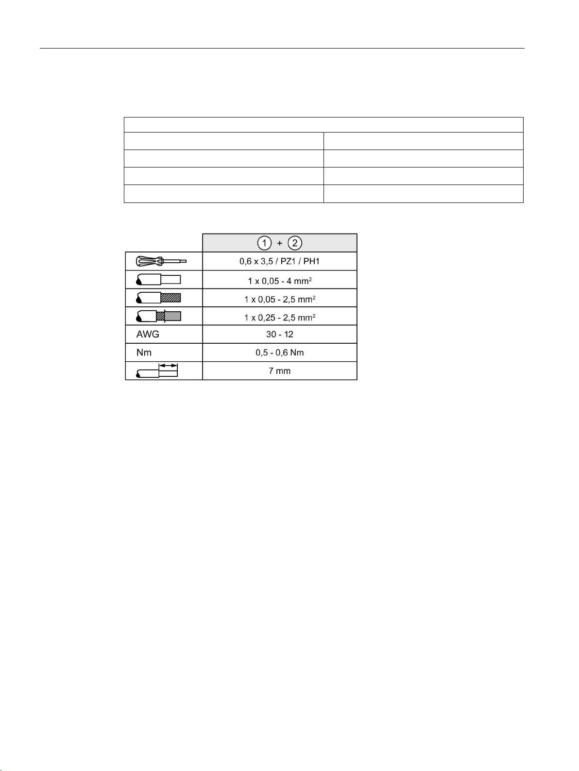
Connections and terminal designations 6EP1566-3AA00
①
①
②
②
2.2 Connections and terminal designation
DC input: "+", "-"
Line input PE
DC output: "+", "-"
line output PE
Figure 2-4 Terminal data for 6EP1566-3AA00
One screw terminal each
1 screw terminal
One screw terminal each
1 screw terminal
SITOP PSU400M
12 Manual, 05.2018, C98130-A7601-A1-5-7629
Description, device design, dimension drawing
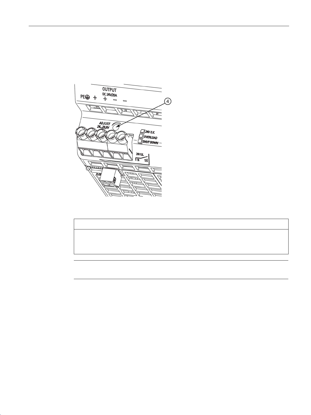
2.3
Potentiometer
NOTICE
Thermal overload possible
Note
It is only permissible to use an
2.3 Potentiometer
The potentiometer ④ on the front of the device is used to adjust the output voltage. The
output voltage is set to 24 V in the factory, and can be adjusted in the range 24 - 28.8 V; for
example, to compensate voltage drops across long supply lines to the connected load.
Figure 2-5 Potentiometer
When adjusting the output voltage to > 24 V, the output current must be derated by 4 %/V,
or the permissible ambient temperature must be taken into account with 3 °C/V.
insulated screwdriver when actuating the potentiometer.
For notes on actuating the potentiometer (screwdriver, torque), see Chapter Figure 2-3
Terminal data for 6EP1536-3AA00 (Page 11).
SITOP PSU400M
Manual, 05.2018, C98130-A7601-A1-5-7629
13

Description, device design, dimension drawing
2.4
Operating displays and signaling
6EP1536-3AA00 (24 V/20 A)
position
Yellow LED lit for overload condition (U
< 20 V ± 0.5 V)
LED red flashing for prewarning and latching shutdown as a result of overtemperature
for "24 V O. K."
Signaling
6EP1536-3AA00 (24 V/20 A)
tion)
Signaling contact (3), contacts 13-14 closed
tion)
tion)
tion)
tion)
tion)
2.4 Operating displays and signaling
Operating display LED green, lit for "24 V O. K."
Signaling contact Relay contact (NO contact, contact rating (isolated): 30 V AC/0.5 A, DC 60 V/0.3 A, DC 30 V/1 A)
LED flashing green: During the wait time for a delayed start with selector switch C in the "ON"
out
Red LED lit for latching shutdown as a result of overload (only for selector switch B in the "ON"
position)
LED green (5.1) off
Signaling contact (3), contacts 13-14 open (quiescent posi-
Green LED (5.1) lit
Green LED (5.1) flashing
Signaling contact (3), contacts 13-14 open (quiescent posi-
Yellow LED (5.2) lit
Signaling contact (3), contacts 13-14 open (quiescent posi-
Green LED (5.1) lit and red LED (5.3) flashing
Signaling contact (3), contacts 13-14 open (quiescent posi-
Red LED (5.3) lit
Signaling contact (3), contacts 13-14 open (quiescent posi-
Red LED (5.3) flashing
Signaling contact (3), contacts 13-14 open (quiescent posi-
No supply voltage
Normal operation, output voltage > 20 V ± 0.5 V
Output voltage = 0 V during delayed start
Overload (U
Prewarning due to overtemperature, device switches off
after approx. 10 s and latches in this condition. (reset possible after approx. 3 min with power OFF/ON)
Latching shutdown due to overload
Shutdown due to overtemperature → reset using power
OFF/ON after approx. 3 min
< 20 V ± 0.5 V)
out
SITOP PSU400M
14 Manual, 05.2018, C98130-A7601-A1-5-7629
Description, device design, dimension drawing
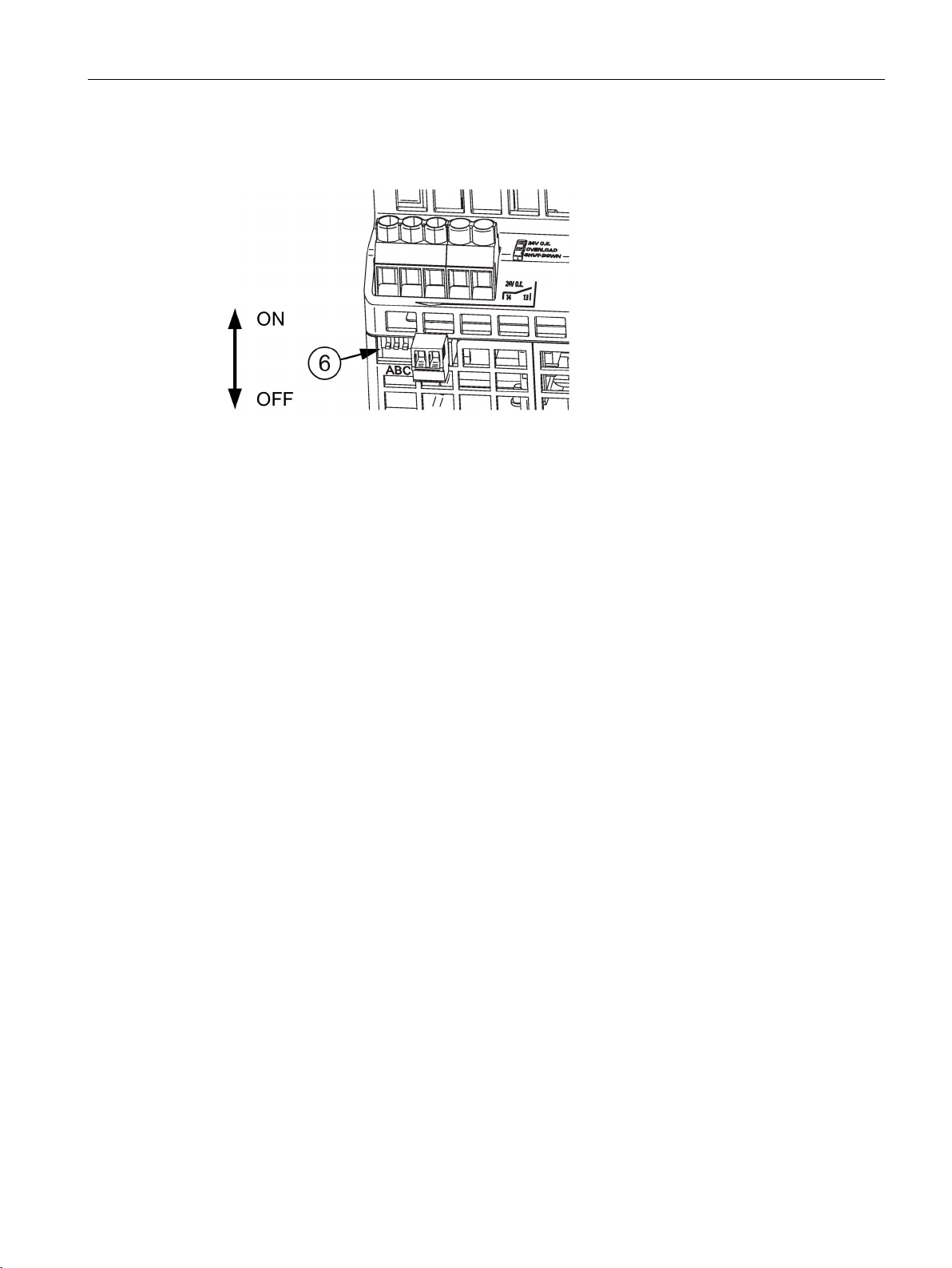
2.5
Selector switch
(A)
Parallel or single mode
(B)
Selectable overload response, constant current characteristic or latching shutdown
(C)
Delayed start
2.5 Selector switch
Figure 2-6 Selector switch
The different operating modes can be selected using selector switch ⑥. You can choose
one of the following modes:
SITOP PSU400M
Manual, 05.2018, C98130-A7601-A1-5-7629
15

Description, device design, dimension drawing
Switch
ON
OFF
A
Parallel operation:
attained.
Single operation:
B
Latching shutdown:
Constant current:
C
Delivery state
Note
Selector switches may only be activated when the device is switched off.
2.5 Selector switch
influences the output
characteristic
in the load range
influences the output
characteristic
in the overload range
Start delay 10 s Immediate start
"Soft" characteristic curve (see
put characteristic parallel operation (Page 37
for the parallel operation of two or more devices: The output voltage falls with increasing
output current (namely, also for the overcurrent
pulse!).
This means that for full output current the highest output voltage can normally no longer be
If the output current rises above the rated value
and above the current limit, the device reduces
the output voltage (see
acteristic latching shutdown (Page 37)). If the
output voltage falls below 20 V, the device
shuts down latching, the red LED lights up. This
limit voltage of 20 V is independent of the set
output voltage. The 'Short-time overload current' feature is not available in this operating
mode. In order to also be able to charge large
capacitances in this operating mode at the
output, non-latching shutdown is performed
during the first ten seconds after power on.
During these first 10 s, the device responds for
overload as if the switch is "OFF".
Figure 6-7 Out-
Figure 6-8 Output char-
Delivery state
"Hard" characteristic curve (see
))
Output characteristic single operation
(Page 36)) for normal operation (single operation): The output voltage is independent of the
output current.
Delivery state
If the output current rises above the rated value
and above the current limit, the device reduces
the output voltage. The yellow LED lights up if
the output voltage falls below 20 V.
Figure 6-6
SITOP PSU400M
16 Manual, 05.2018, C98130-A7601-A1-5-7629
Description, device design, dimension drawing
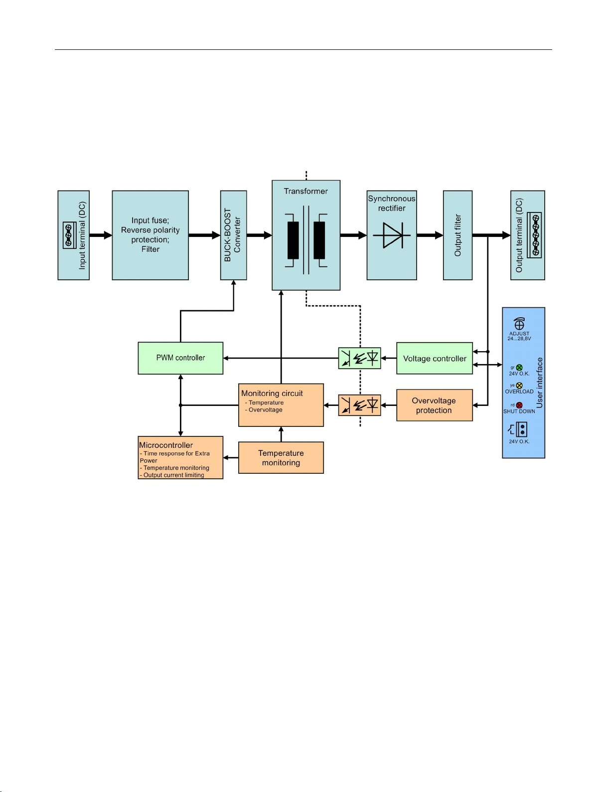
2.6
Block diagram
2.6.1
PSU400M
2.6 Block diagram
Figure 2-7 Block diagram 6EP1536-3AA00
SITOP PSU400M
Manual, 05.2018, C98130-A7601-A1-5-7629
17
Description, device design, dimension drawing
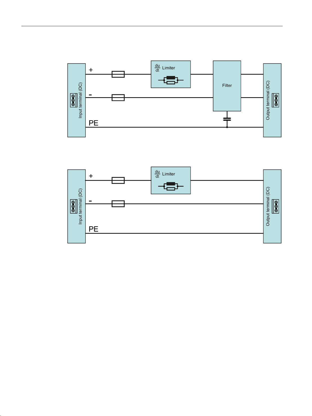
2.6.2
Voltage rise limiter
2.6 Block diagram
Figure 2-8 Block diagram for 6EP1566-3AA00 (product version 1)
Figure 2-9 Block diagram for 6EP1566-3AA00 (product version 2)
SITOP PSU400M
18 Manual, 05.2018, C98130-A7601-A1-5-7629
 Loading...