

Siemens SITOP PSU300S User Manual

___________________
___________________
___________________
___________________
___________________
___________________
___________________
___________________
___________________
___________________
___________________
___________________
SITOP power supply
SITOP PSU300S
Manual
SITOP PSU300S 24 V/5 A
6EP1433
SITOP PSU300S 24 V/10 A
6EP1434
SITOP PSU300S 24 V/20 A
6EP1436
SITOP PSU300S 24 V/40 A
6EP1437
12.2016
C98130
Overview
Safety instructions
1
Description, device design,
dimension drawing
2
Mounting/removal
3
Mounting position, mounting
clearances
4
Installation
5
Technical data
6
Safety, approvals, EMC
7
Ambient conditions
8
Applications
9
Environment
10
Service & Support
11
-2BA20
-2BA20
-2BA10
-2BA20
-A7587-A1-7-7629
Siemens AG
Division Process Industries and Drives
Postfach 48 48
90026 NÜRNBERG
GERMANY
C98130-A7587-A1-7-7629
Ⓟ
Copyright © Siemens AG 2016.
All
Legal information
Warning notice system
DANGER
indicates that death or severe personal injury will result if proper precautions are not taken.
WARNING
indicates that death or severe personal injury may result if proper precautions are not taken.
CAUTION
indicates that minor personal injury can result if proper precautions are not taken.
NOTICE
indicates that property damage can result if proper precautions are not taken.
Qualified Personnel
personnel qualified
Proper use of Siemens products
WARNING
Siemens products may only be used for the applications described in the catalog and in the relevant technical
required to ensure that the products operate safely and without any problems. The permissible
ambient conditions must be complied with. The information in the relevant documentation must be observed.
Trademarks
Disclaimer of Liability
This manual contains notices you have to observe in order to ensure your personal safety, as well as to prevent
damage to property. The notices referring to your personal safety are highlighted in the manual by a safety alert
symbol, notices referring only to property damage have no safety alert symbol. These notices shown below are
graded according to the degree of danger.
If more than one degree of danger is present, the warning notice representing the highest degree of danger will
be used. A notice warning of injury to persons with a safety alert symbol may also include a warning relating to
property damage.
The product/system described in this documentation may be operated only by
task in accordance with the relevant documentation, in particular its warning notices and safety instructions.
Qualified personnel are those who, based on their training and experience, are capable of identifying risks and
avoiding potential hazards when working with these products/systems.
Note the following:
documentation. If products and components from other manufacturers are used, these must be recommended
or approved by Siemens. Proper transport, storage, installation, assembly, commissioning, operation and
maintenance are
All names identified by ® are registered trademarks of Siemens AG. The remaining trademarks in this publication
may be trademarks whose use by third parties for their own purposes could violate the rights of the owner.
We have reviewed the contents of this publication to ensure consistency with the hardware and software
described. Since variance cannot be precluded entirely, we cannot guarantee full consistency. However, the
information in this publication is reviewed regularly and any necessary corrections are included in subsequent
editions.
for the specific
01/2017 Subject to change
rights reserved
Overview
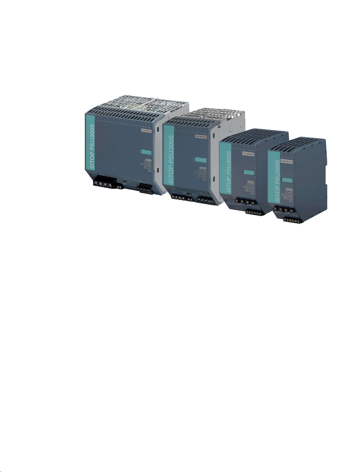
Figure 1 View of units
The 3-phase SITOP PSU300S from the SITOP smart product line is a powerful, regulated
standard power supply for automated machines and systems. In addition to a high efficiency,
these low-profile power supply units have an outstanding overload behavior.
The key benefits of the product include:
● Wide-range input, which allows it to be connected to almost any 3-phase line supply
around the world
● Output voltage can be adjusted in the range 24 - 28 V
● Brief overload capability of 150% for 5 s/min (extra power)
● Continuous overload capability of 120% up to an ambient temperature of 45 °C
● Integrated signaling contact for "24 V O.K."
● No lateral mounting clearances are required
● ambient temperature -25 ... 70 °C
● To increase the system availability, these reliable power supplies can be expanded using
SITOP supplementary modules (redundancy module, selectivity module, buffer module),
as well as SITOP DC-UPS modules.
SITOP PSU300S
Manual, 12.2016, C98130-A7587-A1-7-7629
3

Overview
Ordering data
Regulated SITOP PSU300S power supply
Type
Order number
24 V /10 A output
24 V /20 A output
24 V /40 A output
Accessories
Type
Order number
Device identification labels 20 mm × 7 mm, pastel turquoise
3RT1900-1SB20
The following device options are available:
Input 3AC 400 - 500 V,
24 V/5 A output
Input 3AC 400 - 500 V,
Input 3AC 400 - 500 V,
Input 3AC 400 - 500 V,
6EP1433-2BA20
6EP1434-2BA20
6EP1436-2BA10
6EP1437-2BA20
SITOP PSU300S
4 Manual, 12.2016, C98130-A7587-A1-7-7629

Table of contents
Overview................................................................................................................................................. 3
1 Safety instructions ................................................................................................................................... 7
2 Description, device design, dimension drawing........................................................................................ 9
3 Mounting/removal ................................................................................................................................. 19
4 Mounting position, mounting clearances ................................................................................................ 21
5 Installation ............................................................................................................................................ 31
6 Technical data ...................................................................................................................................... 35
2.1 Device description ..................................................................................................................... 9
2.2 Connections and terminal designation.................................................................................... 10
2.3 Potentiometer .......................................................................................................................... 12
2.4 Status displays and signaling ................................................................................................. 13
2.5 Block diagram ......................................................................................................................... 14
2.6 Dimensions and weight ........................................................................................................... 16
4.1 Standard mounting position .................................................................................................... 21
4.2 Other mounting positions ........................................................................................................ 23
4.2.1 6EP1433-2BA20 ..................................................................................................................... 23
4.2.2 6EP1434-2BA20 ..................................................................................................................... 25
4.2.3 6EP1436-2BA10 ..................................................................................................................... 27
4.2.4 6EP1437-2BA20 ..................................................................................................................... 29
5.1 Line-side connection ............................................................................................................... 31
5.2 Output-side connection ........................................................................................................... 33
6.1 Input ........................................................................................................................................ 35
6.2 Output ..................................................................................................................................... 36
6.3 Efficiency ................................................................................................................................. 40
6.4 Closed-loop control ................................................................................................................. 42
6.5 Protection and monitoring ....................................................................................................... 43
6.6 MTBF ...................................................................................................................................... 43
6.7 Mechanical system ................................................................................................................. 44
6.8 Accessories ............................................................................................................................. 44
6.9 Dimension drawing ................................................................................................................. 45
SITOP PSU300S
Manual, 12.2016, C98130-A7587-A1-7-7629
5

Table of contents
7 Safety, approvals, EMC ........................................................................................................................ 47
8 Ambient conditions ................................................................................................................................ 51
9 Applications .......................................................................................................................................... 53
10 Environment ......................................................................................................................................... 63
11 Service & Support ................................................................................................................................. 65
7.1 Safety ..................................................................................................................................... 47
7.2 Test voltage ............................................................................................................................ 48
7.3 Approvals ............................................................................................................................... 49
7.4 EMC ....................................................................................................................................... 50
9.1 Parallel connection to increase the power rating ................................................................... 53
9.2 Parallel connection for redundancy ....................................................................................... 55
9.3 Series connection for increased voltage ................................................................................ 57
9.4 Overload protection in the 24 V output circuit ........................................................................ 58
9.5 Protection against short-time voltage dips ............................................................................. 59
9.6 Protecting against longer power failures ................................................................................ 60
SITOP PSU300S
6 Manual, 12.2016, C98130-A7587-A1-7-7629

1
WARNING
Correct handling of the devices
When operating electrical devices, it is inevitable that certain components will carry
dangerous voltages.
Therefore, failure to handle the units properly can result in death or serious physical injury
as well as extensive property damage.
Only appropriately qualified personnel may work on or in the vicinity of this equipment.
Perfect, safe, and reliable operation of this equipment is dependent on proper
transportation, storage, installation and mounting.
Before installation or maintenance work can begin, the system's main switch must be
switched off and measures taken to prevent it being switched on again.
If this instruction is not observed, touching live parts can result in death or serious injury.
SITOP PSU300S
Manual, 12.2016, C98130-A7587-A1-7-7629
7

Safety instructions
SITOP PSU300S
8 Manual, 12.2016, C98130-A7587-A1-7-7629
2
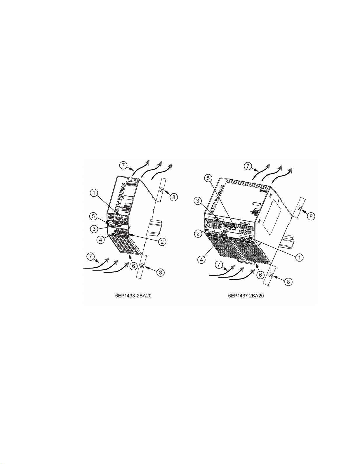
2.1
Device description
①
AC input
②
DC output
③
24 - 28 V potentiometer
④
Signaling contacts (24 V OK)
⑤
Indicator light (24 V OK)
⑥
DIN rail slider
⑦
Natural convection
⑧
Clearance above/below
SITOP PSU300S is a primary-clocked power supply for connection to a 3-phase AC line
supply. An electronically regulated DC voltage that can be set via a potentiometer is
available at the output of the device. The output of the device is isolated, no-load proof and
short-circuit proof. The LED display indicates the operating status. The operating state of the
device can be processed via the signaling contact.
SITOP PSU300S
Manual, 12.2016, C98130-A7587-A1-7-7629
Figure 2-1 Design
9
Description, device design, dimension drawing
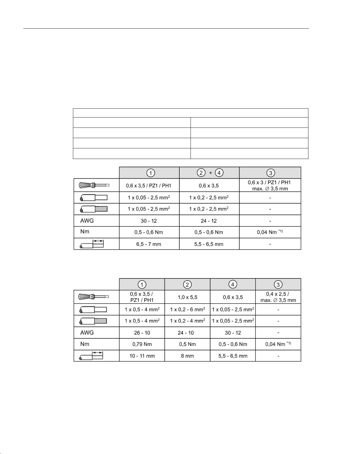
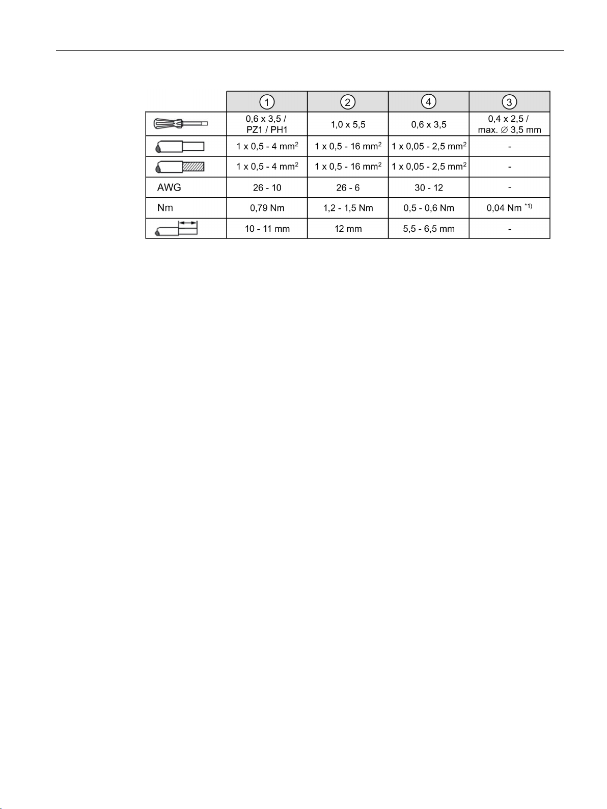
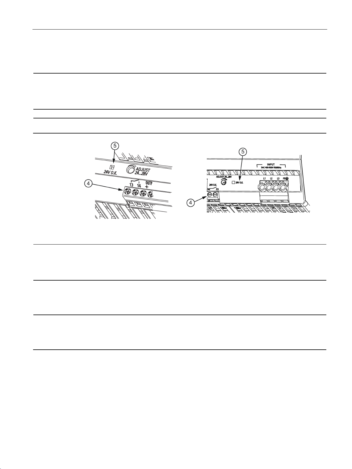
2.2
Connections and terminal designation
Connections and terminal designations
①
②
②
④
*1) Do not subject the end stop to higher loads
*1) Do not subject the end stop to higher loads
2.2 Connections and terminal designation
The line input terminals ① can be used to establish the connection to supply voltage. The
output terminals
Installation (Page 31)).
② are used to connect to the loads to be supplied (see also Section
The operating state of the device can be processed via the signaling contact
and contact rating, see Chapter Status displays and signaling (Page 13)).
line input L1, L2, L3, PE
Output +
Output –
signal 13, 14 (24 V O.K.)
One screw terminal each
2 screw terminals
2 screw terminals
One screw terminal each
④ (function
Figure 2-2 Terminal data for 6EP1433-2BA20 and 6EP1434-2BA20
Figure 2-3 Terminal data for 6EP1436-2BA10
SITOP PSU300S
10 Manual, 12.2016, C98130-A7587-A1-7-7629
Description, device design, dimension drawing
*1) Do not subject the end stop to higher loads
2.2 Connections and terminal designation
Figure 2-4 Terminal data for 6EP1437-2BA20
SITOP PSU300S
Manual, 12.2016, C98130-A7587-A1-7-7629
11
Description, device design, dimension drawing
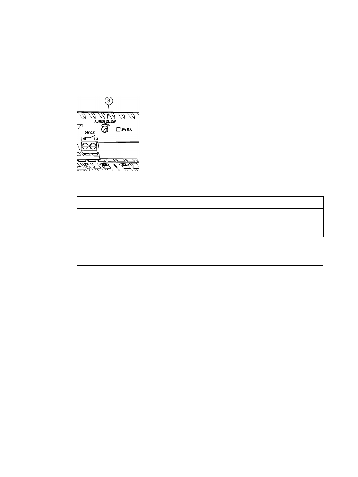
2.3
Potentiometer
NOTICE
Thermal overload possible
Note
It is only permissible to use an insulated screwdriver when actuating the potentiometer.
2.3 Potentiometer
The potentiometer ③ at the front of the device is used to adjust the output voltage. The
output voltage is set to 24 V in the factory, and can be adjusted in the range 24 - 28 V; for
example, to compensate voltage drops across long supply lines to the connected load.
Figure 2-5 Potentiometer (example 6EP1437-2BA20)
When adjusting the output voltage to >24 V, the output current must be derated by 4 %/V,
or the permissible ambient temperature must be taken into account with 3 °C/V.
For notes on actuating the potentiometer (screwdriver, torque), see Figure 2-2 Terminal data
for 6EP1433-2BA20 and 6EP1434-2BA20 (Page 10), Figure 2-3 Terminal data for 6EP14362BA10 (Page 10) and Figure 2-4 Terminal data for 6EP1437-2BA20 (Page 11)
SITOP PSU300S
12 Manual, 12.2016, C98130-A7587-A1-7-7629
Description, device design, dimension drawing
2.4
Status displays and signaling
6EP1433-2BA20 (24 V/5 A)
6EP1434-2BA20 (24 V/10 A)
6EP1436-2BA10 (24 V/20 A)
6EP1437-2BA20 (24 V/40 A)
Status display
LED green for "24V O.K."
"24V O.K."
Signaling
6EP1433-2BA20 (24 V/5 A)
6EP1434-2BA20 (24 V/10 A)
6EP1436-2BA10 (24 V/20 A)
6EP1437-2BA20 (24 V/40 A)
closed
automatically start again after they have cooled down.
2.4 Status displays and signaling
Signaling contact Relay contact (NO contact, contact rating 30 V AC/0.5 A, 60 V DC/0.3 A, 30 V DC/1 A) for
LED ⑤ lights up green
Signaling contact ④,
contact 13 - 14
LED ⑤ dark
Signaling contact ④,
contact 13 - 14 opened
(quiescent position)
Figure 2-6 Operating display and signaling
Normal operation, output voltage >20 V ±0.5 V
Overload / hiccup operation or power supply missing - or the device has tripped due to an
overtemperature or overvoltage condition (caused by an external voltage at the output)
(reset after approximately 120 s by switching off and on again). When 6EP1433-2BA20 and
6EP1433-2BA20 devices trip as a result of an overtemperature condition, these devices
SITOP PSU300S
Manual, 12.2016, C98130-A7587-A1-7-7629
13
Description, device design, dimension drawing
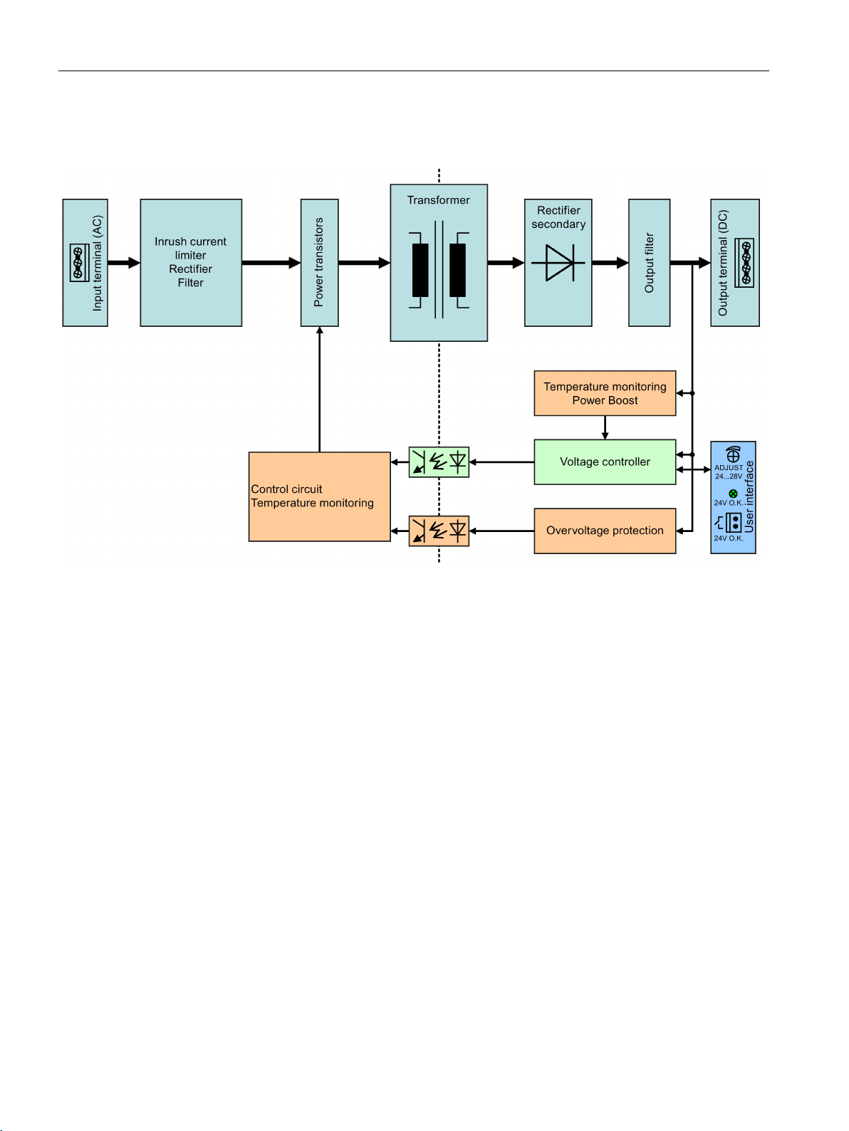
2.5
Block diagram
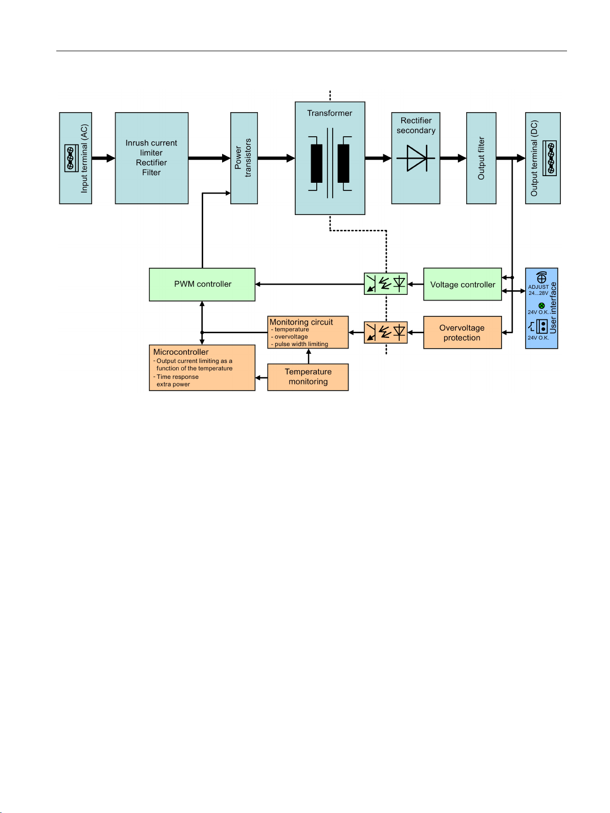
2.5 Block diagram
Figure 2-7 Block diagram for 6EP1433-2BA20 and 6EP1434-2BA20
SITOP PSU300S
14 Manual, 12.2016, C98130-A7587-A1-7-7629
Description, device design, dimension drawing
2.5 Block diagram
Figure 2-8 Block diagram for 6EP1436-2BA10 and 6EP1437-2BA10
SITOP PSU300S
Manual, 12.2016, C98130-A7587-A1-7-7629
15
Description, device design, dimension drawing
2.6
Dimensions and weight
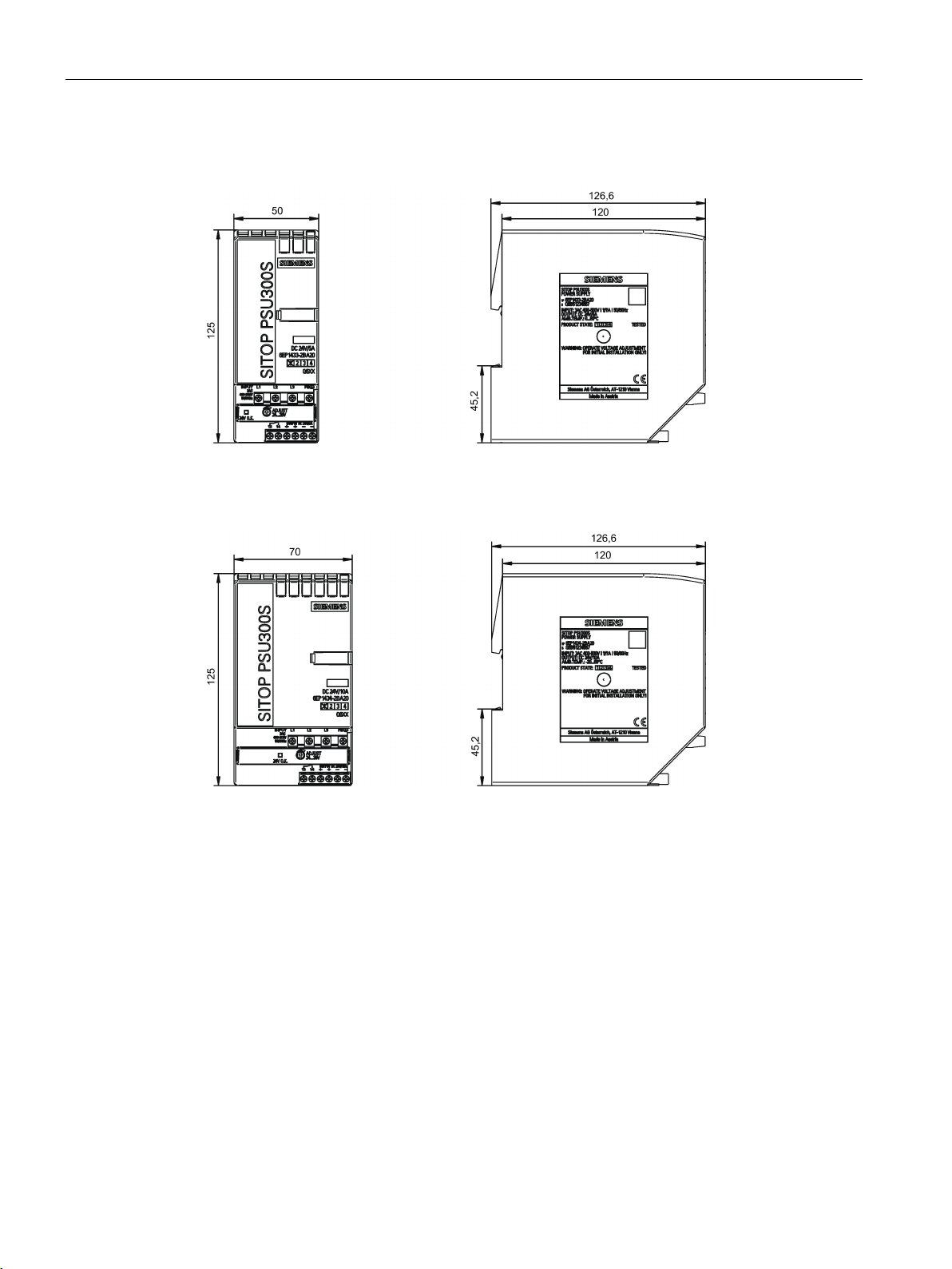
2.6 Dimensions and weight
Figure 2-9 Dimension drawing 6EP1433-2BA20
Figure 2-10 Dimension drawing 6EP1434-2BA20
SITOP PSU300S
16 Manual, 12.2016, C98130-A7587-A1-7-7629
Description, device design, dimension drawing
6EP1433-2BA20
(24 V/5 A)
6EP1434-2BA10
(24 V/10 A)
6EP1436-2BA10
(24 V/20 A)
6EP1437-2BA20
(24 V/40 A)
(W × H × D) in mm
Weight
Approx. 0.5 kg
Approx. 0.7 kg
Approx. 1.6 kg
approx. 3.1 kg
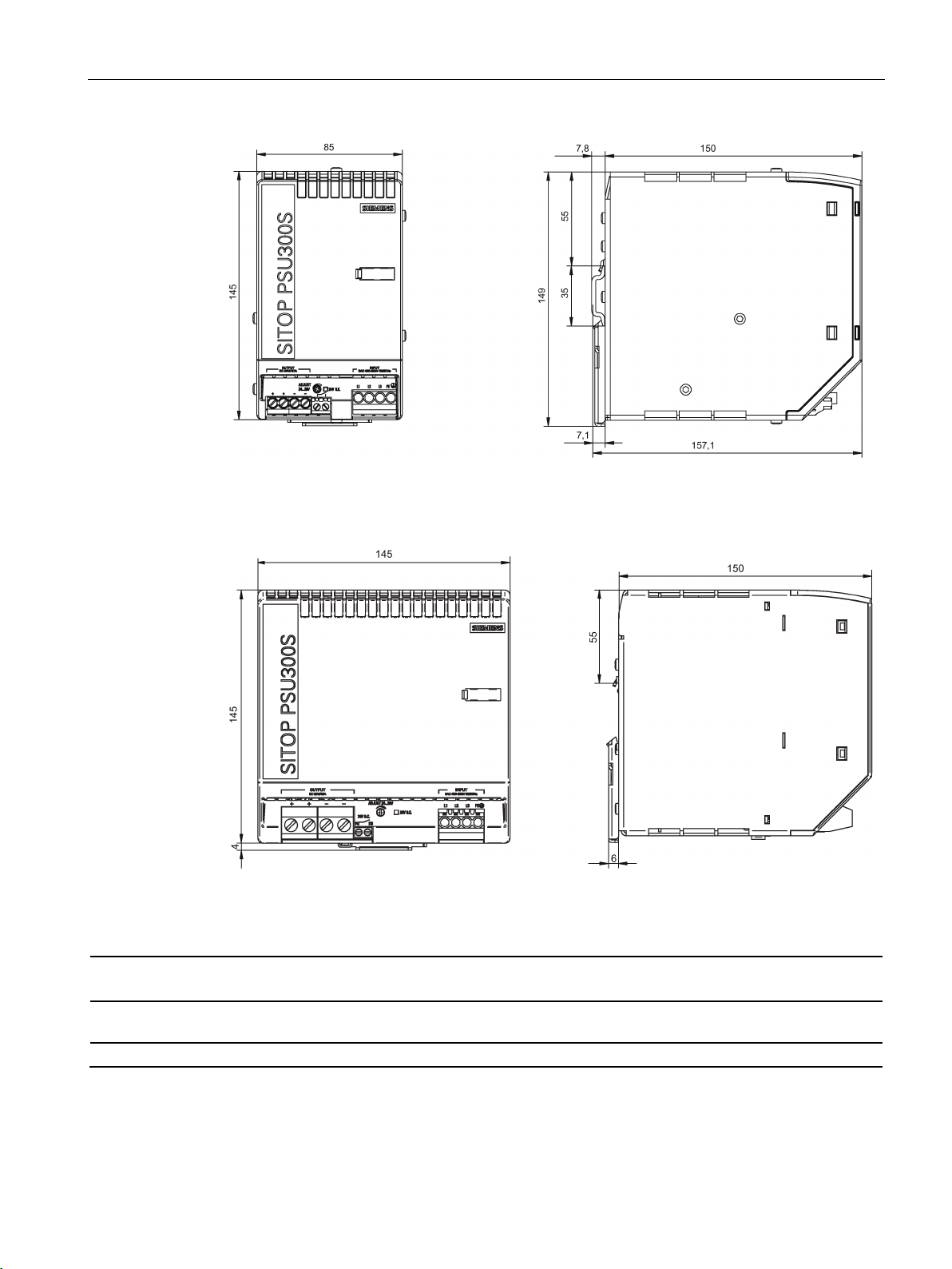
2.6 Dimensions and weight
Figure 2-11 Dimension drawing 6EP1436-2BA10
Dimensions
SITOP PSU300S
Manual, 12.2016, C98130-A7587-A1-7-7629
Figure 2-12 Dimension drawing 6EP1437-2BA20
50 × 125 × 120 70 × 125 × 120 90 × 145 × 150 145 × 145 × 150
17

Description, device design, dimension drawing
2.6 Dimensions and weight
SITOP PSU300S
18 Manual, 12.2016, C98130-A7587-A1-7-7629
3
WARNING
Installing the device in a housing or a control cabinet
Mounting
Removing
The SITOP PSU300S power supply is a built-in device. It must be installed in a housing or
control cabinet, to which only qualified personnel have access.
The device can be mounted in a control cabinet on standard mounting rails (see Chapter
Mechanical system (Page 44))
To mount the device, position it with the mounting rail guide at the upper edge of the
standard mounting rail and press down to lock it into place. If it is too difficult to snap the
device into place, press the slider at the same time, as described under "Removal".
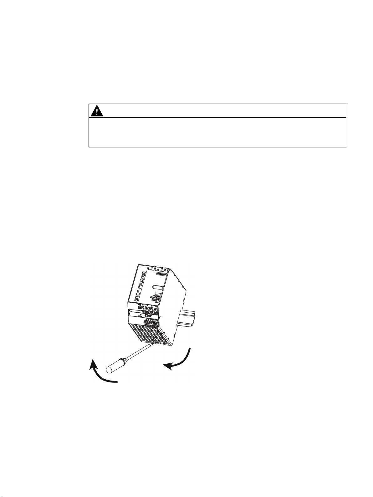
To remove, pull up the slider using a screwdriver and disengage the device at the bottom
edge of the standard mounting rail. Then you can remove the device from the upper edge of
the standard mounting rail.
Figure 3-1 Removing
SITOP PSU300S
Manual, 12.2016, C98130-A7587-A1-7-7629
19

Mounting/removal
WARNING
Use in hazardous zones
If the device is to be used in a hazardous zone (Ex II 3G Ex nA nC IIC T3; Ex II 3G Ex nA
nC IIC T4) it must be installed in a distribution box with degree of protection IP54 or higher.
SITOP PSU300S
20 Manual, 12.2016, C98130-A7587-A1-7-7629
 Loading...