

Siemens SITOP series, SITOP PSU200M 24 V/5 A, SITOP PSU200M 24 V/10 A, SITOP modular 24 V/20 A, SITOP PSU100M 24 V/40 A Operating Instructions Manual

SITOP modular 1ph/2ph
___________________
___________________
___________________
___________________
___________________
___________________
___________________
___________________
___________________
___________________
___________________
___________________
SITOP power supply
SITOP modular 1ph/2ph
Operating Instructions
SITOP PSU200M 24 V/5 A
6EP1333
SITOP PSU200M 24
6EP1334
SITOP modular 24
6EP1336
SITOP PSU100M 24
6EP1337-3BA00
06.2014
C98130
Overview
Safety instructions
1
Description, device design,
dimension drawing
2
Mounting/removal
3
Mounting position, mounting
clearances
4
Installation
5
Technical data
6
Safety, approvals, EMC
7
Ambient conditions
8
Applications
9
Environment
10
Service & Support
11
-3BA10
V/10 A
-3BA10
V/20 A
-3BA00
V/40 A
-A7548-A1-3-7629
Siemens AG
Industry Sector
Postfach 48 48
90026 NÜRNBERG
GERMANY
C98130-A7548-A1-3-7629
Ⓟ
Copyright © Siemens AG 2014.
All rights reserved
Legal information
Warning notice system
DANGER
indicates that death or severe personal injury will result if proper precautions are not taken.
WARNING
indicates that death or severe personal injury may result if proper precautions are not taken.
CAUTION
indicates that minor personal injury can result if proper precautions are not taken.
NOTICE
indicates that property damage can result if proper precautions are not taken.
Qualified Personnel
personnel qualified
Proper use of Siemens products
WARNING
Siemens products may only be used for the applications described in the catalog and in the relevant technical
maintenance are required to ensure that the products operate safely and without any problems. The permissible
ambient conditions must be complied with. The information in the relevant documentation must be observed.
Trademarks
Disclaimer of Liability
This manual contains notices you have to observe in order to ensure your personal safety, as well as to prevent
damage to property. The notices referring to your personal safety are highlighted in the manual by a safety alert
symbol, notices referring only to property damage have no safety alert symbol. These notices shown below are
graded according to the degree of danger.
If more than one degree of danger is present, the warning notice representing the highest degree of danger will
be used. A notice warning of injury to persons with a safety alert symbol may also include a warning relating to
property damage.
The product/system described in this documentation may be operated only by
task in accordance with the relevant documentation, in particular its warning notices and safety instructions.
Qualified personnel are those who, based on their training and experience, are capable of identifying risks and
avoiding potential hazards when working with these products/systems.
for the specific
Note the following:
documentation. If products and components from other manufacturers are used, these must be recommended
or approved by Siemens. Proper transport, storage, installation, assembly, commissioning, operation and
All names identified by ® are registered trademarks of Siemens AG. The remaining trademarks in this publication
may be trademarks whose use by third parties for their own purposes could violate the rights of the owner.
We have reviewed the contents of this publication to ensure consistency with the hardware and software
described. Since variance cannot be precluded entirely, we cannot guarantee full consistency. However, the
information in this publication is reviewed regularly and any necessary corrections are included in subsequent
editions.
07/2014 Subject to change
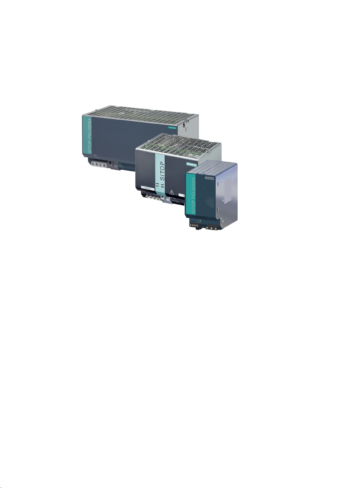
Overview
The 1-phase/2-phase power supply from the SITOP modular product line is a powerful,
stabilized technology power supply for automated machines and systems.
The key benefits of the product include:
● Wide-range input, which allows it to be connected to almost any 1-phase/2-phase line
supply around the world
● Output voltage can be adjusted in the range 24...28.8 V
● Power boost during operation with 300% rated current for 25 ms
● No lateral mounting clearances are required
● Ambient temperature -25 (0)...+70° C
● Selectable short-circuit response (constant current or latching shutdown)
● A soft characteristic can be selected for a parallel connection (for uniform load distribution
of power supply units of the same type)
● Display of the operating state via 3 LEDs
● To increase the system availability, these reliable power supplies can be expanded using
SITOP supplementary modules (redundancy module, selectivity module, buffer module,
signaling module or signaling contact), as well as SITOP DC-UPS modules.
SITOP modular 1ph/2ph
Operating Instructions, 06.2014, C98130-A7548-A1-3-7629
3

Overview
Ordering data
Stabilized power supply unit SITOP modular 1ph/2ph
Type
Order number
24 V/5 A output
24 V/10 A output
24 V/20 A output
24 V /40 A output
The following device options are available:
120-230/230-500 VAC input,
120-230/230-500 VAC input,
120/230 VAC input,
120/230 VAC input,
6EP1333-3BA10
6EP1334-3BA10
6EP1336-3BA00
6EP1337-3BA00
SITOP modular 1ph/2ph
4 Operating Instructions, 06.2014, C98130-A7548-A1-3-7629

Table of contents
Overview................................................................................................................................................. 3
1 Safety instructions ................................................................................................................................... 7
2 Description, device design, dimension drawing........................................................................................ 9
3 Mounting/removal ................................................................................................................................. 21
4 Mounting position, mounting clearances ................................................................................................ 23
5 Installation ............................................................................................................................................ 33
6 Technical data ...................................................................................................................................... 37
2.1 Device description .......................................................................................................................... 9
2.2 Connections and terminal designation ......................................................................................... 10
2.3 Potentiometer ............................................................................................................................... 12
2.4 Status displays and signaling ....................................................................................................... 13
2.5 Change-over switch ..................................................................................................................... 14
2.6 Block diagram .............................................................................................................................. 16
2.7 Dimensions and weight ................................................................................................................ 18
4.1 Standard mounting position ......................................................................................................... 23
4.2 Other mounting positions ............................................................................................................. 25
4.2.1 6EP1333-3BA10 .......................................................................................................................... 25
4.2.2 6EP1334-3BA10 .......................................................................................................................... 27
4.2.3 6EP1336-3BA00 .......................................................................................................................... 29
4.2.4 6EP1337-3BA00 .......................................................................................................................... 31
5.1 Line-side connection .................................................................................................................... 33
5.2 Output-side connection ................................................................................................................ 36
6.1 Input ............................................................................................................................................. 37
6.2 Output .......................................................................................................................................... 39
6.3 Efficiency ...................................................................................................................................... 46
6.4 Closed-loop control ...................................................................................................................... 48
6.5 Protection and monitoring ............................................................................................................ 48
6.6 MTBF ........................................................................................................................................... 48
6.7 Mechanical system ...................................................................................................................... 49
6.8 Accessories .................................................................................................................................. 49
6.9 Dimension drawing ...................................................................................................................... 50
SITOP modular 1ph/2ph
Operating Instructions, 06.2014, C98130-A7548-A1-3-7629
5

Table of contents
7 Safety, approvals, EMC ........................................................................................................................ 51
8 Ambient conditions ................................................................................................................................ 55
9 Applications .......................................................................................................................................... 57
10 Environment ......................................................................................................................................... 67
11 Service & Support ................................................................................................................................. 69
7.1 Safety .......................................................................................................................................... 51
7.2 Test voltage ................................................................................................................................. 52
7.3 Approvals .................................................................................................................................... 54
7.4 EMC ............................................................................................................................................ 54
9.1 Parallel connection to increase power rating .............................................................................. 57
9.2 Parallel connection for redundancy ............................................................................................. 59
9.3 Series connection for increased voltage ..................................................................................... 61
9.4 Overload protection in the 24 V output circuit ............................................................................. 62
9.5 Protection against short-time voltage dips .................................................................................. 63
9.6 Protecting against longer power failures ..................................................................................... 64
SITOP modular 1ph/2ph
6 Operating Instructions, 06.2014, C98130-A7548-A1-3-7629

1
WARNING
Correct handling of the devices
When operating electrical devices, it is inevitable that certain components will carry
dangerous voltages.
Therefore, failure to handle the units properly can result in death or serious physical injury
as well as extensive property damage.
Only appropriately qualified personnel may work on or in the vicinity of this equipment.
Perfect, safe, and reliable operation of this equipment is dependent on proper
transportation, storage, installation and mounting.
Before installation or maintenance work can begin, the system's main switch must be
switched off and measures taken to prevent it being switched on again.
If this instruction is not observed, touching live parts can result in death or serious injury.
SITOP modular 1ph/2ph
Operating Instructions, 06.2014, C98130-A7548-A1-3-7629
7

Safety instructions
SITOP modular 1ph/2ph
8 Operating Instructions, 06.2014, C98130-A7548-A1-3-7629
2
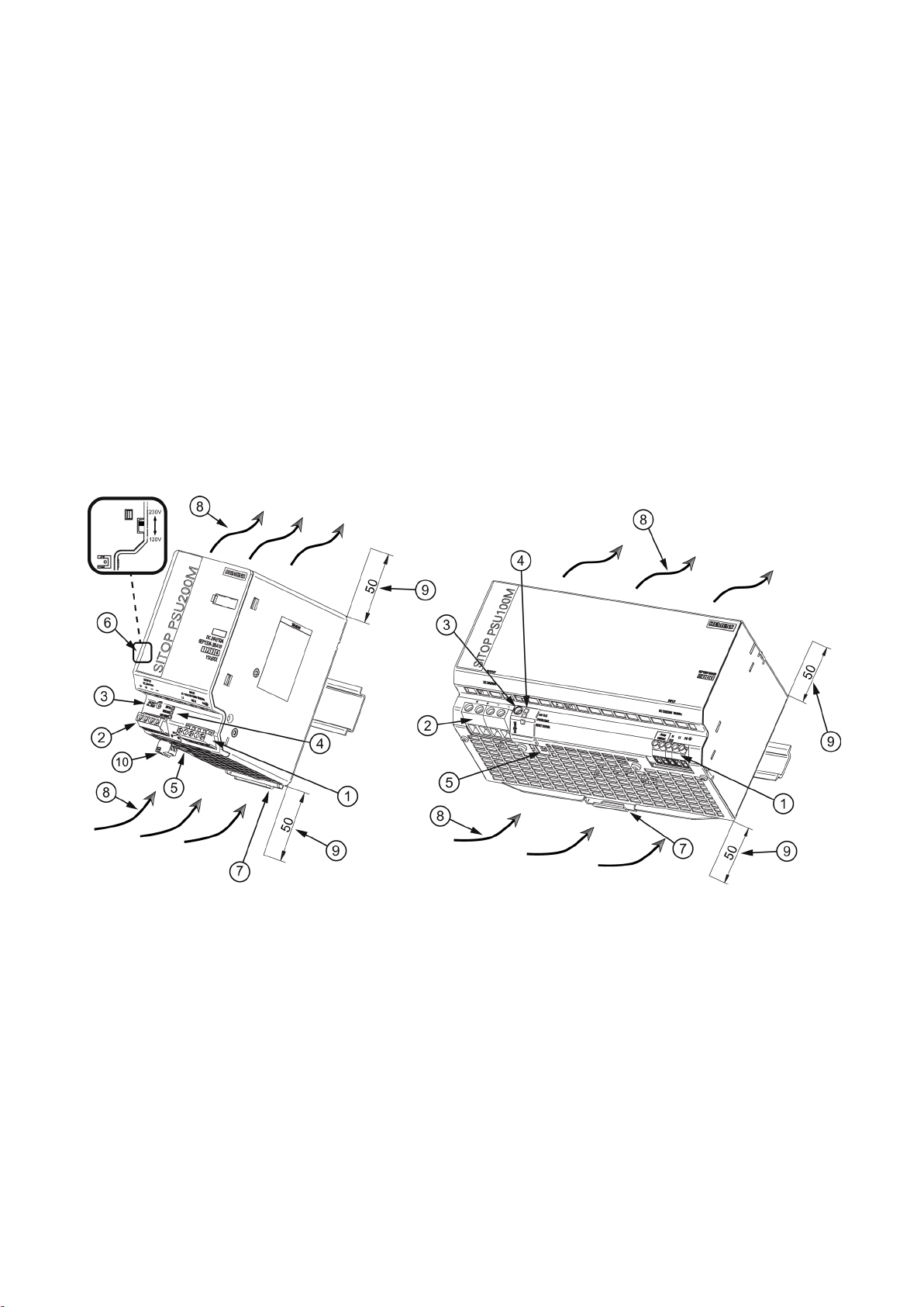
2.1
Device description
①
Line input
②
DC output
③
Potentiometer 24...28.8 V
④
Pilot lamps (24 V OK, OVERLOAD, SHUTDOWN)
⑤
A/B selector switch
⑥
Voltage selector switch (only for 6EP1333-3BA10 and 6EP1334-3BA10)
⑦
DIN rail slider
⑧
Natural convection
⑨
Clearance above/below
⑩
Signaling contact (only for 6EP1333-3BA10 and 6EP1334-3BA10)
SITOP modular is a primary-clocked power supply for connection to a 1-phase/2-phase AC
line supply. An electronically regulated DC voltage that can be set via a potentiometer is
available at the output of the device. The output of the device is isolated, no-load proof and
short-circuit proof. The LED displays indicate the operating state. The integrated signaling
contact (for 6EP1336-3BA00 and 6EP1337-3BA00, only when using the supplementary
6EP1961-3BA10 signaling module) can be used to further process the operating state of the
device.
Figure 2-1 Design (example, 6EP1334-3BA10 and 6P1337-3BA00)
SITOP modular 1ph/2ph
Operating Instructions, 06.2014, C98130-A7548-A1-3-7629
9
Description, device design, dimension drawing
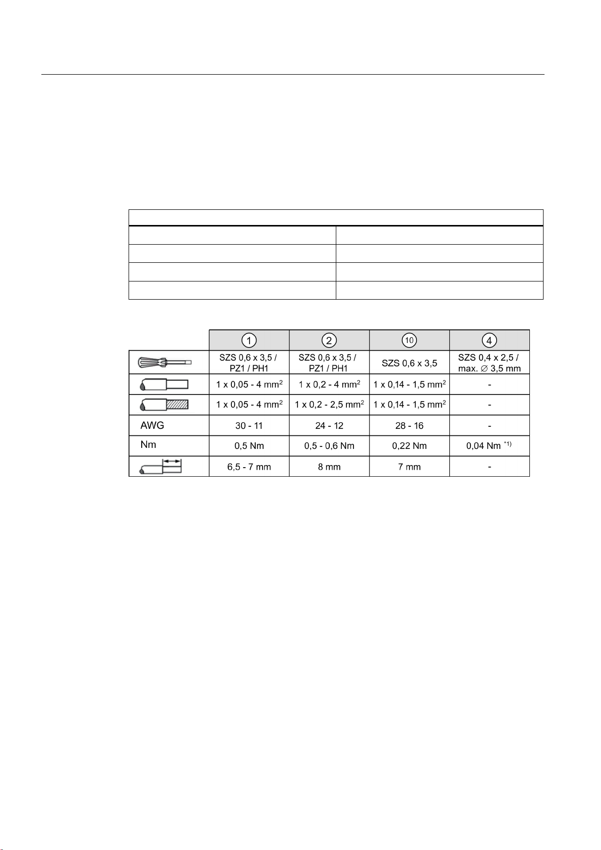
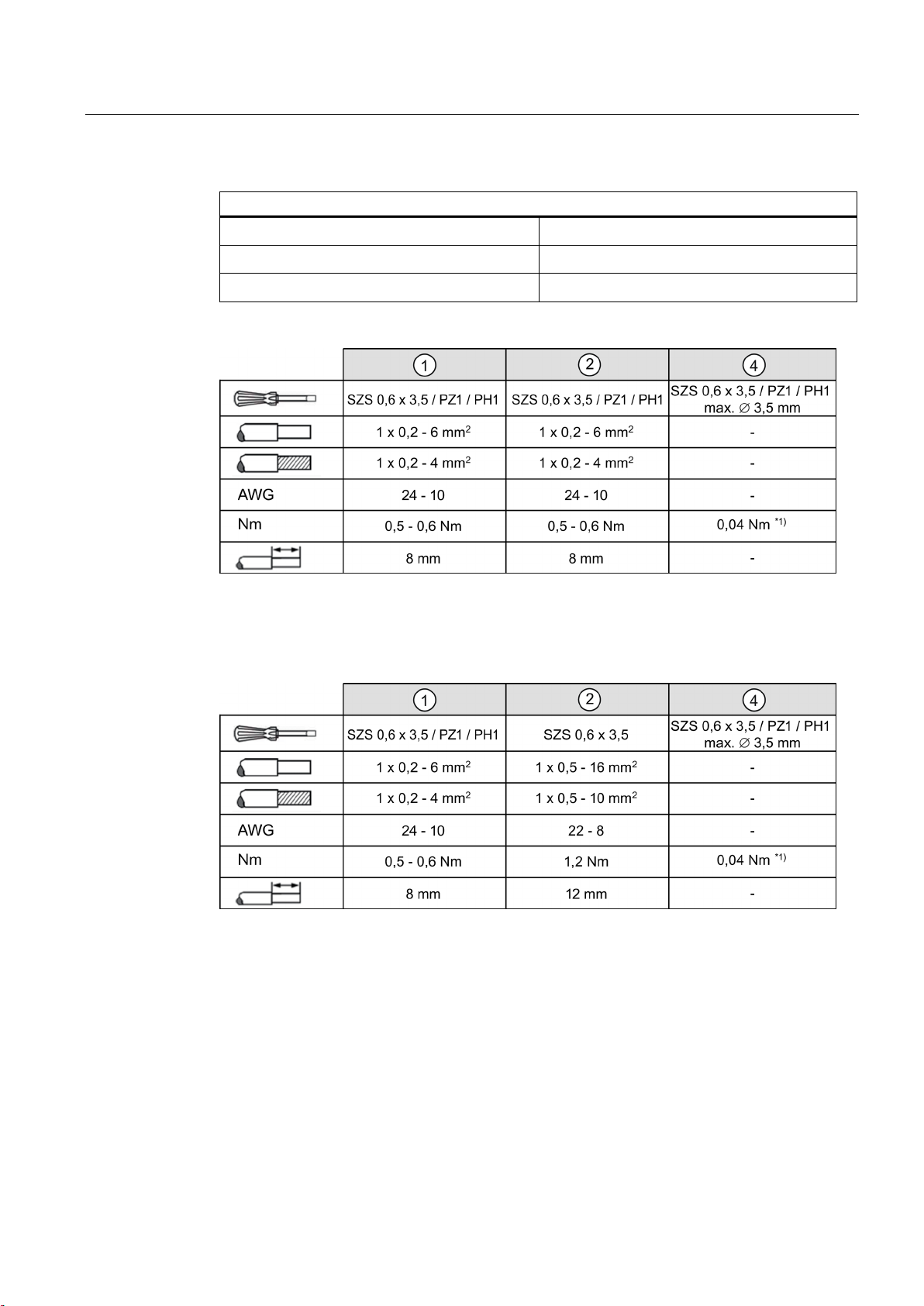
2.2
Connections and terminal designation
Connections and terminal designations for 6EP1333-3BA10 and 6EP1334-3BA10
①
②
②
⑩
Do not subject the end stop to higher loads
2.2 Connections and terminal designation
The line input terminals ① can be used to establish the connection to the supply voltage.
The output terminals
Installation (Page 33)).
② are used to connect to the loads to be supplied (see also Section
Line input L1, N (L2), PE
Output +
Output –
Signaling contact 13, 14
*1)
Figure 2-2 Terminal data for 6EP1333-3BA10 and 6EP1334-3BA10
One screw terminal each
2 screw terminals
2 screw terminals
One screw terminal each
SITOP modular 1ph/2ph
10 Operating Instructions, 06.2014, C98130-A7548-A1-3-7629
Description, device design, dimension drawing
Connections and terminal designations for 6EP1336-3BA00 and 6EP1337-3BA00
①
②
②
Do not subject the end stop to higher loads
Do not subject the end stop to higher loads
2.2 Connections and terminal designation
Line input L1, N (L2), PE, Jump 120 V AC
Output +
Output –
*1)
Figure 2-3 Terminal data for 6EP1336-3BA00
One screw terminal each
2 screw terminals
2 screw terminals
*1)
Figure 2-4 Terminal data for 6EP1337-3BA00
SITOP modular 1ph/2ph
Operating Instructions, 06.2014, C98130-A7548-A1-3-7629
11
Description, device design, dimension drawing
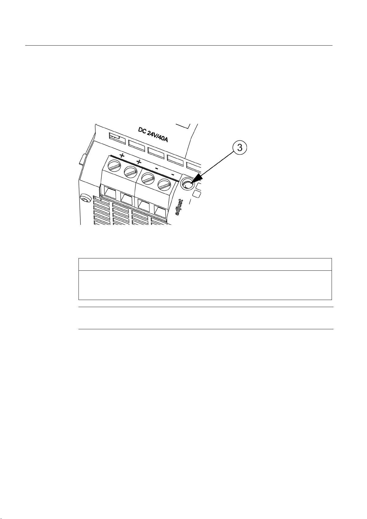
2.3
Potentiometer
NOTICE
Thermal overload possible
Note
It is only permissible to use an insulated screwdriver when actuating the
2.3 Potentiometer
The potentiometer ③ on the front of the device is used to set the output voltage. The output
voltage is set to 24 V in the factory and can be adjusted in the range 24...28.8 V; for
example, to compensate voltage drops across long supply lines to the connected load.
Figure 2-5 Potentiometer (example of 6EP1337-3BA00)
When adjusting the output voltage to >24 V, the output current must be derated by 4 %/V,
or the permissible ambient temperature must be taken into account with 3° C/V.
potentiometer.
For notes on actuating the potentiometer (screwdriver, torque), see Figure 2-2 Terminal data
for 6EP1333-3BA10 and 6EP1334-3BA10 (Page 10), Figure 2-3 Terminal data for 6EP13363BA00 (Page 11) and Figure 2-4 Terminal data for 6EP1337-3BA00 (Page 11).
SITOP modular 1ph/2ph
12 Operating Instructions, 06.2014, C98130-A7548-A1-3-7629
Description, device design, dimension drawing
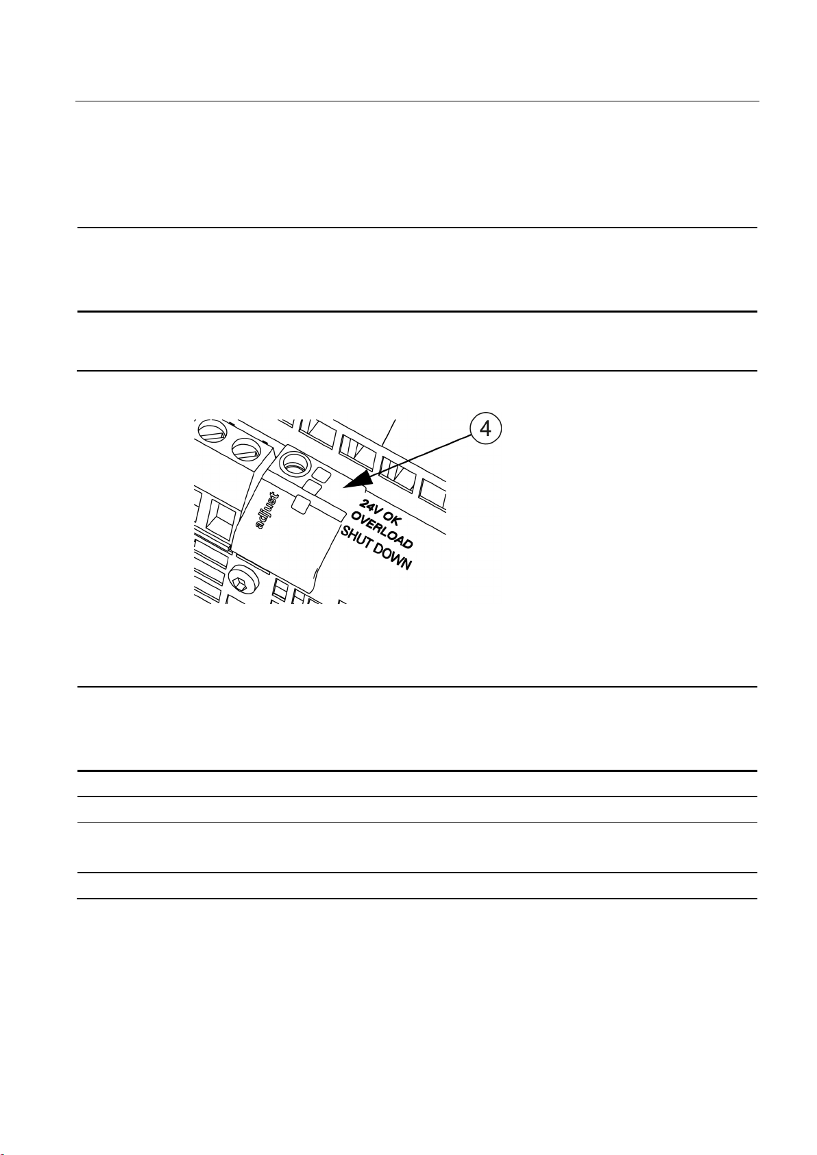
2.4
Status displays and signaling
6EP1333-3BA10 (24 V/5 A)
6EP1334-3BA10 (24 V/10 A)
6EP1336-3BA00 (24 V/20 A)
6EP1337-3BA00 (24 V/40 A)
Red LED for latching shutdown in "shut down" mode
Signaling
6EP1333-3BA10 (24 V/5 A)
6EP1334-3BA10 (24 V/10 A)
6EP1336-3BA00 (24 V/20 A)
6EP1337-3BA00 (24 V/40 A)
supplementary signaling module 6EP1961-3BA10 is used)
2.4 Status displays and signaling
Status indicator Green LED for 24 V O.K.
Yellow LED for overload in "constant current" mode
Figure 2-6 Status indicators and signals (example of 6EP1337-3BA00)
Green LED ④ lights up
Yellow LED ④ lights up
Red LED ④ lights up
Green LED ④ off
Normal operation, output voltage >20 V ±0.5 V
Overload (Ua <20 V ±0.5 V)
Latching shutdown
or remote switch-off for 6EP1336-3BA00 and 6EP1337-3BA00 (only when the
No supply voltage
SITOP modular 1ph/2ph
Operating Instructions, 06.2014, C98130-A7548-A1-3-7629
13
Description, device design, dimension drawing
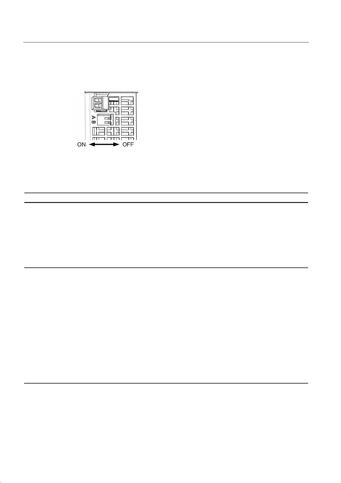
2.5
Change-over switch
Switch
ON
OFF
A
Parallel operation:
be attained.
Single operation:
B
Latching shutdown:
overload as if the switch is OFF.
Constant current:
2.5 Change-over switch
Figure 2-7 A/B selector switch
The two switches A and B are used to influence the output characteristic curve:
influences the output
characteristic in the
load range
influences the output
characteristic in the
overload range
'Soft' characteristic curve (see, e.g. Figure 6-10
6EP1333-3BA10 parallel operation output
characteristic (Page 43)) for the parallel
operation of two or more devices: The output
voltage falls with increasing output current
(namely, also for the overcurrent pulse!).
This means that for full output current the
highest output voltage can normally no longer
If the output current rises above the rated value
and above the current limit, the device reduces
the output voltage (see, e.g. Figure 6-14
6EP1333-3BA10 latching shutdown output
characteristic (Page 44)). If the output voltage
falls below 20 V, the device shuts down
latching, the red LED lights up. This limit
voltage of 20 V is independent of the set output
voltage. The 'Short-time overload current'
feature is not available in this operating mode.
To also permit the uploading of large
capacitances in this operating mode at the
output, a shutdown is performed during the first
10 s after power on or remote on in conjunction
with the non-latching signaling module. During
these first 10 s, the device responds for
Delivery state
'Hard' characteristic curve (see, e.g. Figure 6-3
6EP1333-3BA10 single operation output
characteristic (Page 41)) for normal operation
(single operation): The output voltage is
independent of the output current.
Delivery state
If the output current rises above the rated value
and above the current limit, the device reduces
the output voltage. The yellow LED lights up if
the output voltage falls below 20 V.
SITOP modular 1ph/2ph
14 Operating Instructions, 06.2014, C98130-A7548-A1-3-7629
Delivery state: A - OFF; B - OFF

Description, device design, dimension drawing
2.5 Change-over switch
Selector switch for the input voltage range for 6EP1333-3BA10 (24 V/5 A) and 6EP13343BA10 (24 V/10 A)
Figure 2-8 Voltage selector switch (example, 6EP1334-3BA10)
The selector switch as delivered is in the 230 V position. It must be moved to the appropriate
position for operation in the 120 V range. The selector switch can only be actuated in the deenergized state.
To switch the input voltage range for 6EP1336-3BA00 (24 V/20 A) and 6EP1337-3BA00
(24 V/40 A) to 120 V, a wire jumper must be connected to the input terminal, Jump
120 V AC. This must be dimensioned as for the power supply cable with regard to crosssection and insulation. The length must not exceed 100 mm.
Figure 2-9 Wire jumper (example, 6EP1437-3BA00)
SITOP modular 1ph/2ph
Operating Instructions, 06.2014, C98130-A7548-A1-3-7629
15
Description, device design, dimension drawing
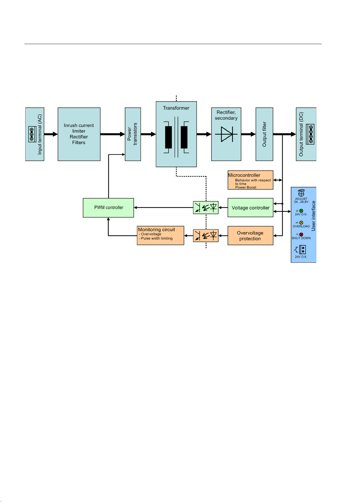
2.6
Block diagram
2.6 Block diagram
Figure 2-10 Block diagram for 6P1333-3BA10 and 6P1334-3BA10
SITOP modular 1ph/2ph
16 Operating Instructions, 06.2014, C98130-A7548-A1-3-7629
Description, device design, dimension drawing
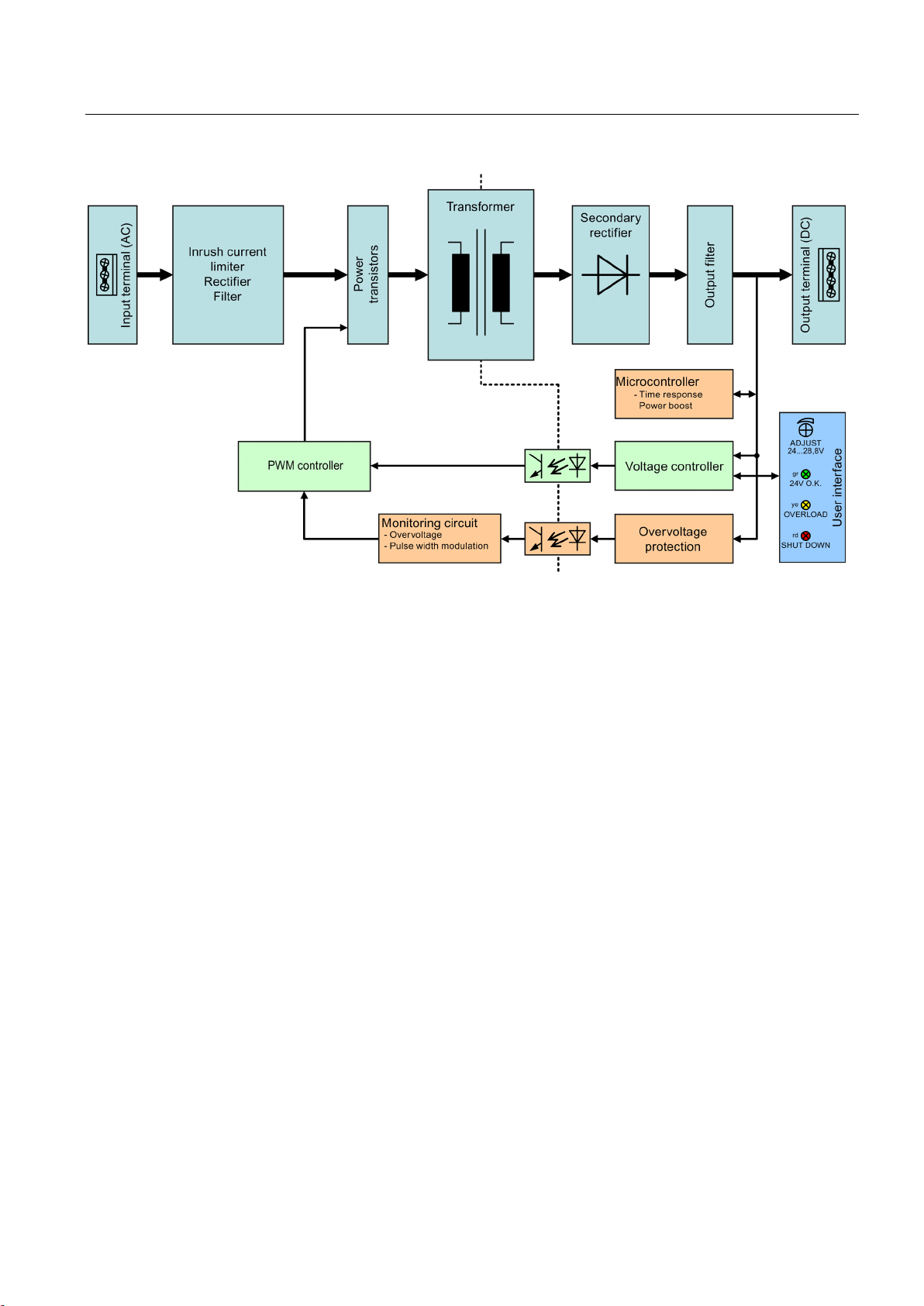
2.6 Block diagram
Figure 2-11 Block diagram for 6P1336-3BA00 and 6P1337-3BA00
SITOP modular 1ph/2ph
Operating Instructions, 06.2014, C98130-A7548-A1-3-7629
17
Description, device design, dimension drawing
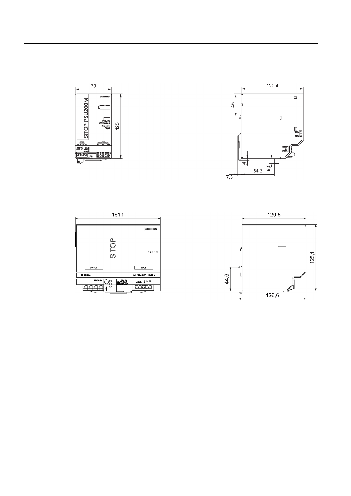
2.7
Dimensions and weight
2.7 Dimensions and weight
Figure 2-12 Dimension drawing, 6EP1333-3BA10 and 6EP1334-3BA10 (example, 6EP1334-3BA10)
Figure 2-13 Dimension drawing for 6EP1336-3BA00
SITOP modular 1ph/2ph
18 Operating Instructions, 06.2014, C98130-A7548-A1-3-7629
Description, device design, dimension drawing
6EP1333-3BA10
(24 V/5 A)
6EP1334-3BA10
(24 V/10 A)
6EP1336-3BA00
(24 V/20 A)
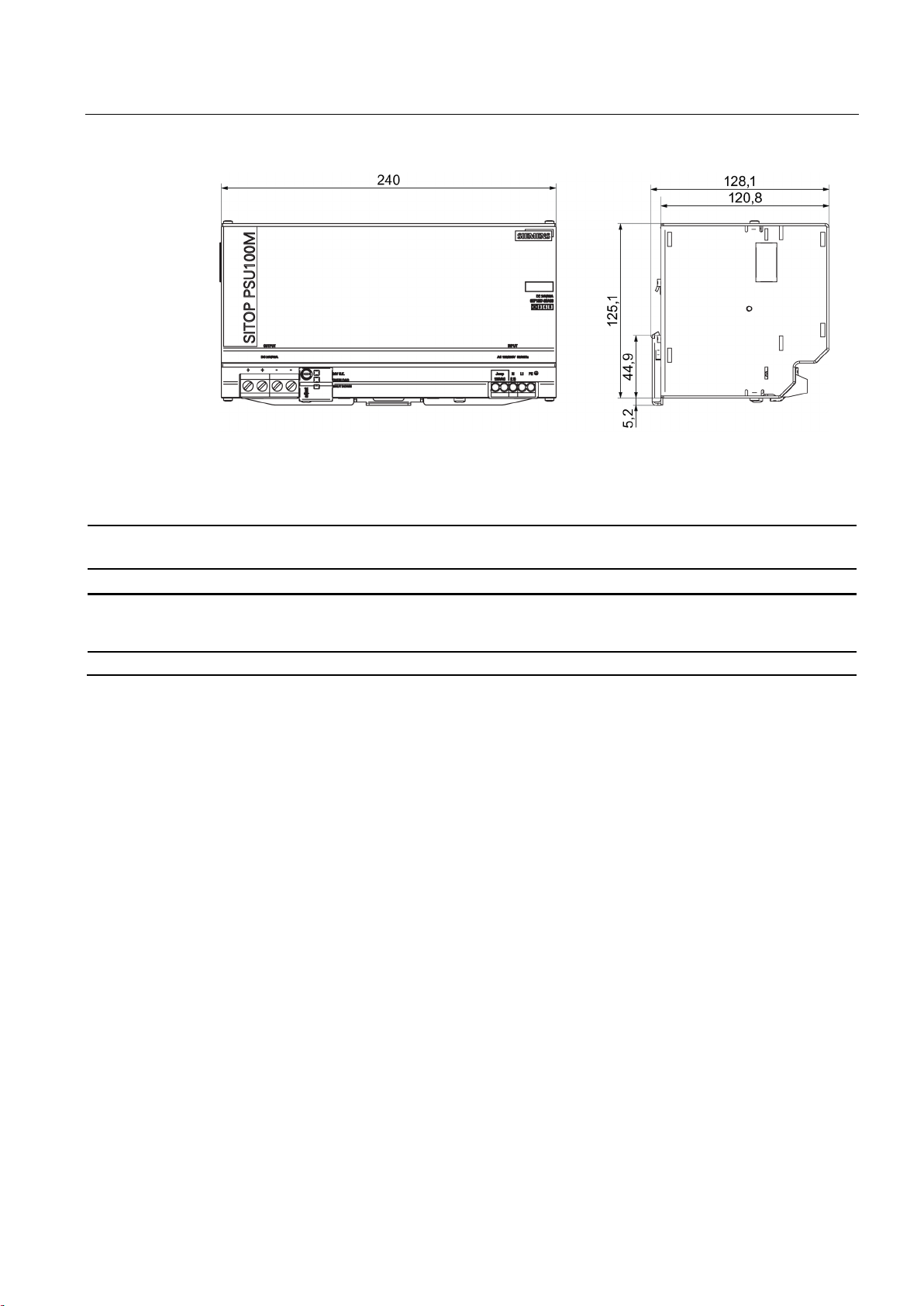
6EP1337-3BA00
(24 V/40 A)
2.7 Dimensions and weight
Figure 2-14 Dimension drawing for 6EP1337-3BA00
Dimensions
(W × H × D) in
mm
Weight Approx. 0.6 kg Approx. 0.8 kg Approx. 2.2 kg Approx. 2.9 kg
70 × 125 × 120,5 70 × 125 × 120,5 160 × 125 × 120,5 240 × 125 × 120,5
SITOP modular 1ph/2ph
Operating Instructions, 06.2014, C98130-A7548-A1-3-7629
19

Description, device design, dimension drawing
2.7 Dimensions and weight
SITOP modular 1ph/2ph
20 Operating Instructions, 06.2014, C98130-A7548-A1-3-7629
3
WARNING
Installing the device in a housing or a control cabinet
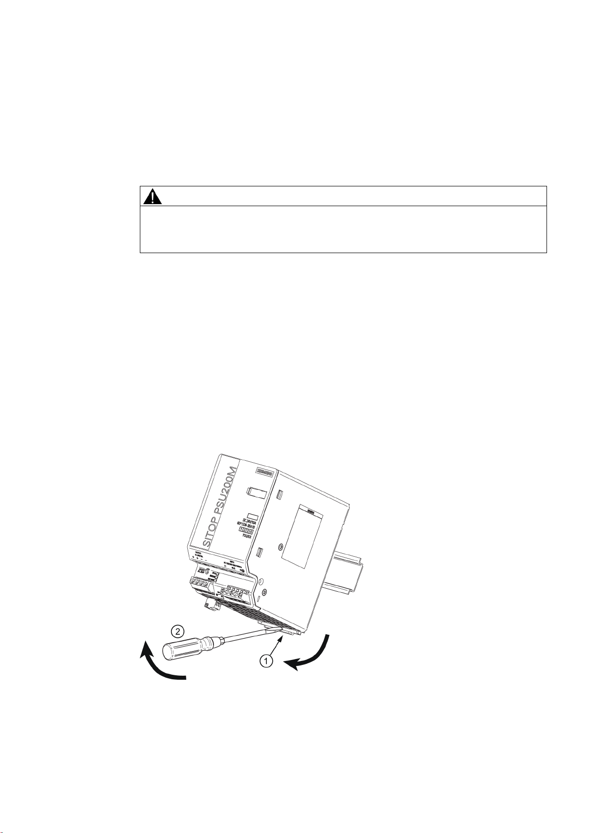
Mounting
Removing
The SITOP modular power supply is a built-in device. It must be installed in a housing or
control cabinet, to which only qualified personnel have access.
The device can be mounted in a control cabinet on standard mounting rails according to
EN 60715.
To mount the device, position it with the mounting rail guide at the upper edge of the
standard mounting rail and press down to lock it into place. If this is too difficult, press slider
① at the same time, as described under "Removal".
To remove, pull up the slider ① using a screwdriver ② and disengage the device at the
bottom edge of the standard mounting rail. Then you can remove the device from the upper
edge of the standard mounting rail.
Figure 3-1 Removal (example, 6EP1334-3BA10)
SITOP modular 1ph/2ph
Operating Instructions, 06.2014, C98130-A7548-A1-3-7629
21
 Loading...