

Siemens SITOP PSU100C,6EP1321-5BA00, 6EP1322-5BA10, 6EP1332-5BA1, 6EP1331-5BA00, 6EP1331-5BA10 Operating Instructions Manual
...
SITOP PSU100C
_
_________________
_
_
_________________
_
_
_________________
_
_
_________________
_
_
_________________
_
_
_________________
_
_
_________________
_
_
_________________
_
_
_________________
_
_
_________________
_
_
_________________
_
_
_________________
_
SITOP power supply
SITOP PSU100C
Operating Instructions
SITOP PSU100C 12 V/2 A
6EP1321-5BA00
SITOP PSU100C 12 V/6.5 A
6EP1322-5BA10
SITOP PSU100C 24 V/0.6 A
6EP1331-5BA00
SITOP PSU100C 24 V/1.3 A
6EP1331-5BA10
SITOP PSU100C 24 V/2.5 A
6EP1332-5BA00
SITOP PSU100C 24 V/3.7 A
6EP1332-5BA20
SITOP PSU100C 24 V/4 A
6EP1332-5BA10
06.2013
C98130-A7599-A1-2-7629
Overview
Safety instructions
1
Description, device design,
dimension drawing
2
Mounting/disassembly
3
Mounting position, mounting
clearances
4
Installation
5
Technical data
6
Safety, approvals, EMC
7
Ambient conditions
8
Applications
9
Environment
10
Service & Support
11
Siemens AG
Industry Sector
Postfach 48 48
90026 NÜRNBERG
GERMANY
C98130-A7599-A1-2-7629
Ⓟ 06/2013 Technical data subject to change
Copyright © Siemens AG 2013.
All rights reserved
Legal information
Warning notice system
This manual contains notices you have to observe in order to ensure your personal safety, as well as to prevent
damage to property. The notices referring to your personal safety are highlighted in the manual by a safety alert
symbol, notices referring only to property damage have no safety alert symbol. These notices shown below are
graded according to the degree of danger.
DANGER
indicates that death or severe personal injury will result if proper precautions are not taken.
WARNING
indicates that death or severe personal injury may result if proper precautions are not taken.
CAUTION
indicates that minor personal injury can result if proper precautions are not taken.
NOTICE
indicates that property damage can result if proper precautions are not taken.
If more than one degree of danger is present, the warning notice representing the highest degree of danger will
be used. A notice warning of injury to persons with a safety alert symbol may also include a warning relating to
property damage.
Qualified Personnel
The product/system described in this documentation may be operated only by personnel qualified for the specific
task in accordance with the relevant documentation, in particular its warning notices and safety instructions.
Qualified personnel are those who, based on their training and experience, are capable of identifying risks and
avoiding potential hazards when working with these products/systems.
Proper use of Siemens products
Note the following:
WARNING
Siemens products may only be used for the applications described in the catalog and in the relevant technical
documentation. If products and components from other manufacturers are used, these must be recommended
or approved by Siemens. Proper transport, storage, installation, assembly, commissioning, operation and
maintenance are required to ensure that the products operate safely and without any problems. The permissible
ambient conditions must be complied with. The information in the relevant documentation must be observed.
Trademarks
All names identified by ® are registered trademarks of Siemens AG. The remaining trademarks in this publication
may be trademarks whose use by third parties for their own purposes could violate the rights of the owner.
Disclaimer of Liability
We have reviewed the contents of this publication to ensure consistency with the hardware and software
described. Since variance cannot be precluded entirely, we cannot guarantee full consistency. However, the
information in this publication is reviewed regularly and any necessary corrections are included in subsequent
editions.
SITOP PSU100C
Operating Instructions, 06.2013, C98130-A7599-A1-2-7629
3
Overview
The key benefits of the product include:
● Power supply with wide range input for operation on 1-phase AC line supplies or a DC
voltage
● Small mounting footprint as a result of the low-profile design
● Low energy usage as a result of the high efficiency over the complete load range
● Minimum energy losses for no-load operation (<0.75 W)
● Can be snapped onto and removed from mounting rails without requiring any tools
● Connection using plug-in terminals
● Wide operating temperature range from -20 °C up to +70 °C (derating from
+50 °C / 55 °C)
● International package of standards

Overview
SITOP PSU100C
4 Operating Instructions, 06.2013, C98130-A7599-A1-2-7629
Ordering data
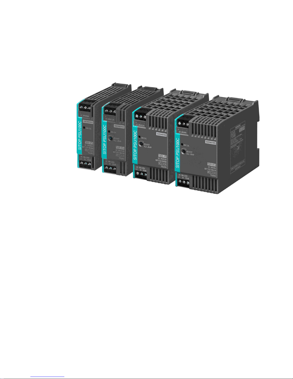
The following device options are available:
SITOP PSU100C primary-clocked power supply
Type Order number
Input 100 - 230 V AC
120 - 230 V DC
Output 12 V DC / 2 A
6EP1321-5BA00
Input 100 - 230 V AC
120 - 230 V DC
Output 12 V DC / 6.5 A
6EP1322-5BA10
Input 100 - 230 V AC
120 - 230 V DC
Output 24 V DC / 0.6 A
6EP1331-5BA00
Input 100 - 230 V AC
120 - 230 V DC
Output 24 V DC / 1.3 A
6EP1331-5BA10
Input 100 - 230 V AC
120 - 230 V DC
Output 24 V DC / 2.5 A
6EP1332-5BA00
Input 100 - 230 V AC
120 - 230 V DC
Output 24 V DC / 3.7 A
6EP1332-5BA20
Input 100 - 230 V AC
120 - 230 V DC
Output 24 V DC / 4 A
6EP1332-5BA10
Accessories
Type Order number
Pluggable spring-loaded terminal 6EP1971-5BA00 (packing unit): 100 terminals, for 50 SITOP
PSU100C power supplies)

SITOP PSU100C
Operating Instructions, 06.2013, C98130-A7599-A1-2-7629
5
Table of contents
Overview.................................................................................................................................................... 3
1
Safety instructions ..................................................................................................................................... 7
2
Description, device design, dimension drawing ......................................................................................... 9
2.1
Device description..........................................................................................................................9
2.2
Connections and terminal designation.........................................................................................10
2.3
Potentiometer...............................................................................................................................11
2.4
Operating displays and signaling.................................................................................................12
2.5
Block diagram ..............................................................................................................................13
2.6
Dimensions and weight................................................................................................................14
3
Mounting/disassembly ............................................................................................................................. 17
4
Mounting position, mounting clearances.................................................................................................. 19
4.1
Standard mounting position .........................................................................................................19
4.2
Other mounting positions .............................................................................................................22
5
Installation ............................................................................................................................................... 23
5.1
Line-side connection ....................................................................................................................23
5.2
Output-side connection................................................................................................................25
6
Technical data ......................................................................................................................................... 27
6.1
Input .............................................................................................................................................27
6.2
Output ..........................................................................................................................................29
6.3
Efficiency and power loss ............................................................................................................32
6.4
Closed-loop control ......................................................................................................................36
6.5
Protection and monitoring............................................................................................................37
6.6
MTBF ...........................................................................................................................................37
6.7
Mechanical system ......................................................................................................................37
6.8
Accessories..................................................................................................................................39
6.9
Dimension drawing ......................................................................................................................39
7
Safety, approvals, EMC ........................................................................................................................... 41
7.1
Safety ...........................................................................................................................................41
7.2
Test voltage..................................................................................................................................42
7.3
Certifications ................................................................................................................................43
7.4
EMC .............................................................................................................................................44

Table of contents
SITOP PSU100C
6 Operating Instructions, 06.2013, C98130-A7599-A1-2-7629
8 Ambient conditions .................................................................................................................................. 45
9 Applications ............................................................................................................................................. 47
9.1
Parallel connection to increase the power rating ........................................................................ 47
9.2
Parallel connection for redundancy............................................................................................. 49
9.3
Series connection for increased voltage ..................................................................................... 51
9.4
Protection against short-time voltage dips.................................................................................. 52
10
Environment ............................................................................................................................................ 53
11
Service & Support.................................................................................................................................... 55

SITOP PSU100C
Operating Instructions, 06.2013, C98130-A7599-A1-2-7629
7
Safety instructions
1
WARNING
Correct handling of the devices
When operating electrical devices, it is inevitable that certain components will carry
dangerous voltages.
Therefore, failure to handle the units properly can result in death or serious physical injury
as well as extensive property damage.
Only appropriately qualified personnel may work on or in the vicinity of this equipment.
Perfect, safe, and reliable operation of this equipment is dependent on proper
transportation, storage, installation and mounting.
Before installation or maintenance work can begin, the system's main switch must be
switched off and measures taken to prevent it being switched on again.
If this instruction is not observed, touching live parts can result in death or serious injury.

Safety instructions
SITOP PSU100C
8 Operating Instructions, 06.2013, C98130-A7599-A1-2-7629
SITOP PSU100C
Operating Instructions, 06.2013, C98130-A7599-A1-2-7629
9
Description, device design, dimension drawing
2
2.1 Device description
SITOP PSU100C are primary clocked power supplies for connection to a 1-phase AC line
supply or to DC power systems. An electronically regulated DC voltage that can be set via a
potentiometer is available at the output of the device (not for the devices: 6EP1331-5BA00,
6EP1332-5BA20). The output of the device is isolated, no-load proof and short-circuit proof.
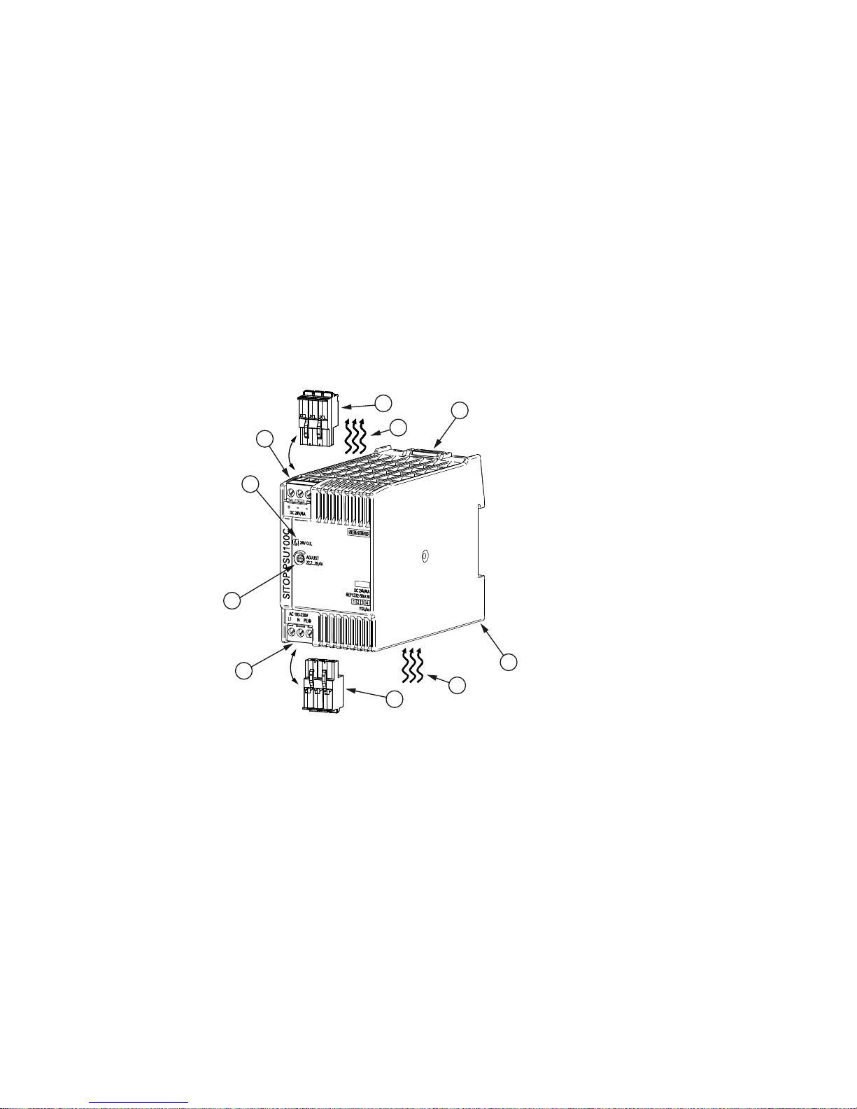
The LED display indicates the operating status.
① Line input (pluggable screw terminal)
② DC output (pluggable screw terminal)
③ Indicator light (output voltage OK)
④ Potentiometer 22.2…26.4 V/10.5…12.9 V
⑤ Slider to manually release
⑥ Lug for releasing with a screwdriver
⑦ Spring-loaded terminal MLFB 6EP1971-5BA00 (accessory)
⑧ Natural convection
Figure 2-1 Design (example: 6EP1332-5BA10)
Description, device design, dimension drawing
2.2 Connections and terminal designation
SITOP PSU100C
10 Operating Instructions, 06.2013, C98130-A7599-A1-2-7629
2.2 Connections and terminal designation
The line input terminals ① can be used to establish the connection to supply voltage. The
output terminals
② are used to connect to the loads to be supplied (see also Section
Installation (Page 23)).
Connections and terminal designations
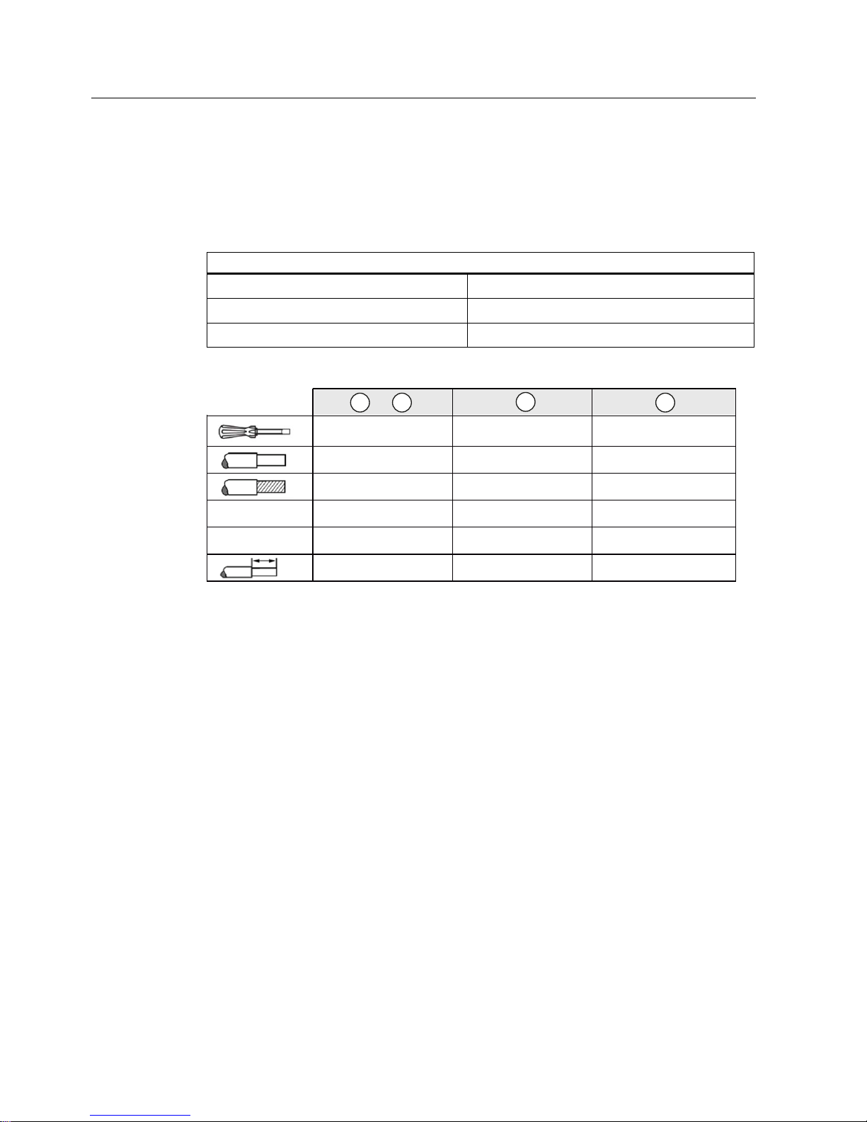
① line input L, N, PE
One screw terminal each for 0.5 to 2.5 mm²
② Output +
1 screw terminal for 0.5...2.5 mm²
② Output –
2 screw terminals for 0.5...2.5 mm²
$:*
1P
6=6[3=3+
6=6[
6=6[3=3+
PD[ෘPP
[PP
[PP
[PP
[PP
1P
1P
PP PP
Figure 2-2 Terminal data
Description, device design, dimension drawing
2.3 Potentiometer
SITOP PSU100C
Operating Instructions, 06.2013, C98130-A7599-A1-2-7629
11
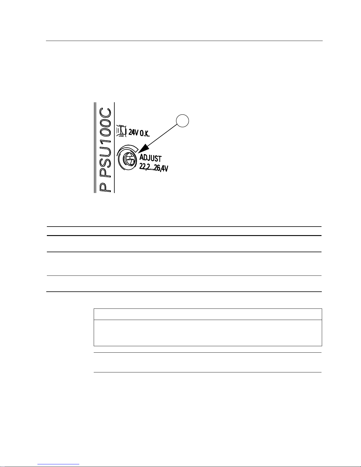
2.3 Potentiometer
The potentiometer ④ on the front of the device is used to adjust the output voltage. The
output voltage is set to the rated value at the factory and can be set within certain limits; for
example, to compensate voltage drops across long supply lines to the connected load.
Figure 2-3 Potentiometer (example 6EP1332-5BA10)
Type Factory setting Setting range
6EP1321-5BA00 (12 V/2 A)
6EP1322-5BA10 (12 V/6.5 A)
12 V 10.5...12.9 V
6EP1331-5BA10 (24 V/1.3 A)
6EP1332-5BA00 (24 V/2.5 A)
6EP1332-5BA10 (24 V/4 A)
24 V 22.2...26.4 V
6EP1331-5BA00 (24 V/0.6 A)
6EP1332-5BA20 (24 V/3.7 A)
24 V -
The following devices do not have a potentiometer: 6EP1331-5BA00 and 6EP1332-5BA20.
NOTICE
Thermal overload possible
When adjusting the output voltage to >24 V or >12 V, the output current must be derated by
4%/V.
Note
It is only permissible to activate the potentiometer using an insulated screwdriver.
For notes on actuating the potentiometer (screwdriver, torque), see Figure 2-2 Terminal data
(Page 10).
Description, device design, dimension drawing
2.4 Operating displays and signaling
SITOP PSU100C
12 Operating Instructions, 06.2013, C98130-A7599-A1-2-7629
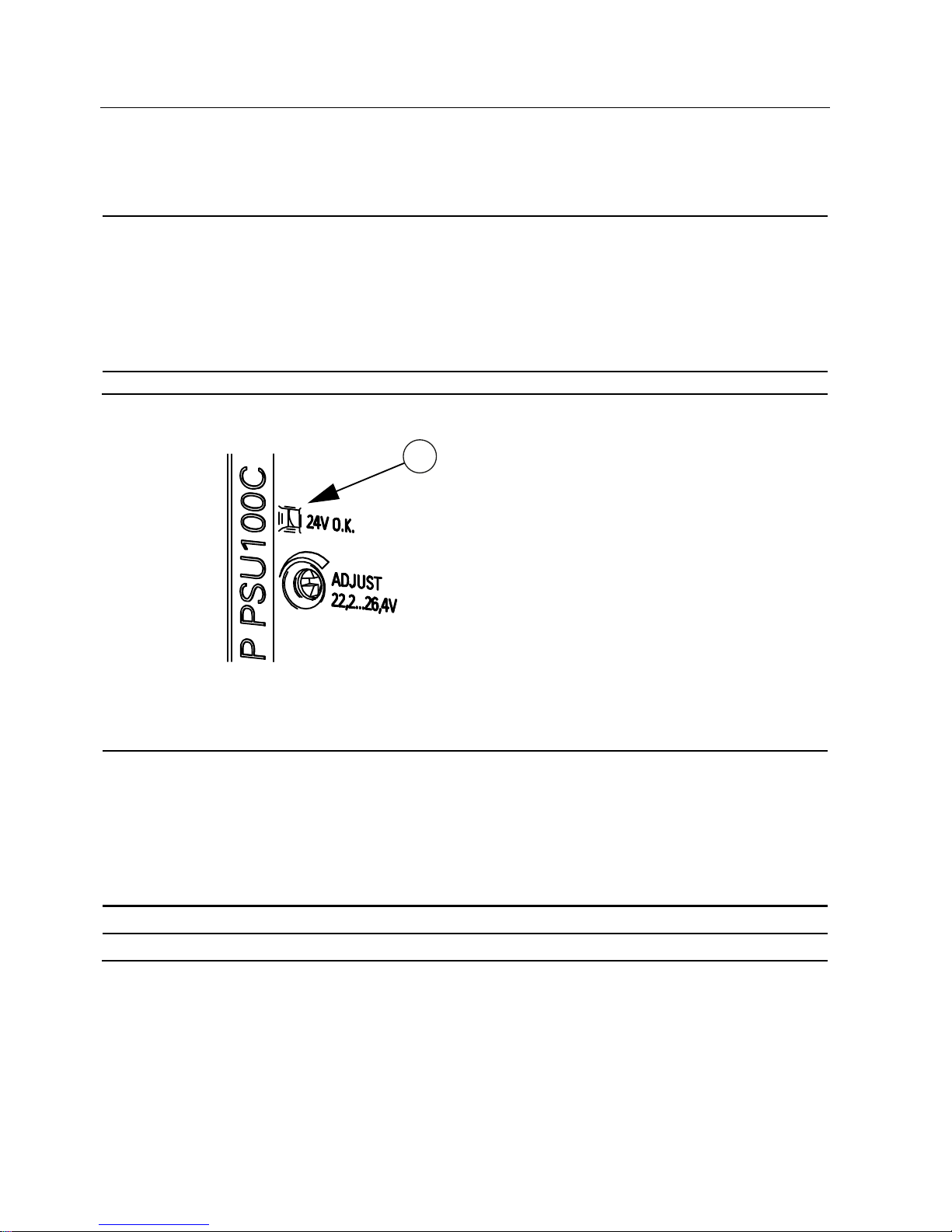
2.4 Operating displays and signaling
6EP1321-5BA00 (12 V/2 A)
6EP1322-5BA10 (12 V/6.5 A)
6EP1331-5BA00 (24 V/0.6 A)
6EP1331-5BA10 (24 V/1.3 A)
6EP1332-5BA00 (24 V/2.5 A)
6EP1332-5BA20 (24 V/3.7 A)
6EP1332-5BA10 (24 V/4 A)
Operating display Green LED for output voltage OK
Figure 2-4 Operating displays and signals (example of 6EP1332-5BA10)
Signaling 6EP1321-5BA00 (12 V/2 A)
6EP1322-5BA10 (12 V/6.5 A)
6EP1331-5BA00 (24 V/0.6 A)
6EP1331-5BA10 (24 V/1.3 A)
6EP1332-5BA00 (24 V/2.5 A)
6EP1332-5BA20 (24 V/3.7 A)
6EP1332-5BA10 (24 V/4 A)
LED ③ lights up green
Normal operation, output voltage present
LED ③ off
Output voltage not present
Description, device design, dimension drawing
2.5 Block diagram
SITOP PSU100C
Operating Instructions, 06.2013, C98130-A7599-A1-2-7629
13
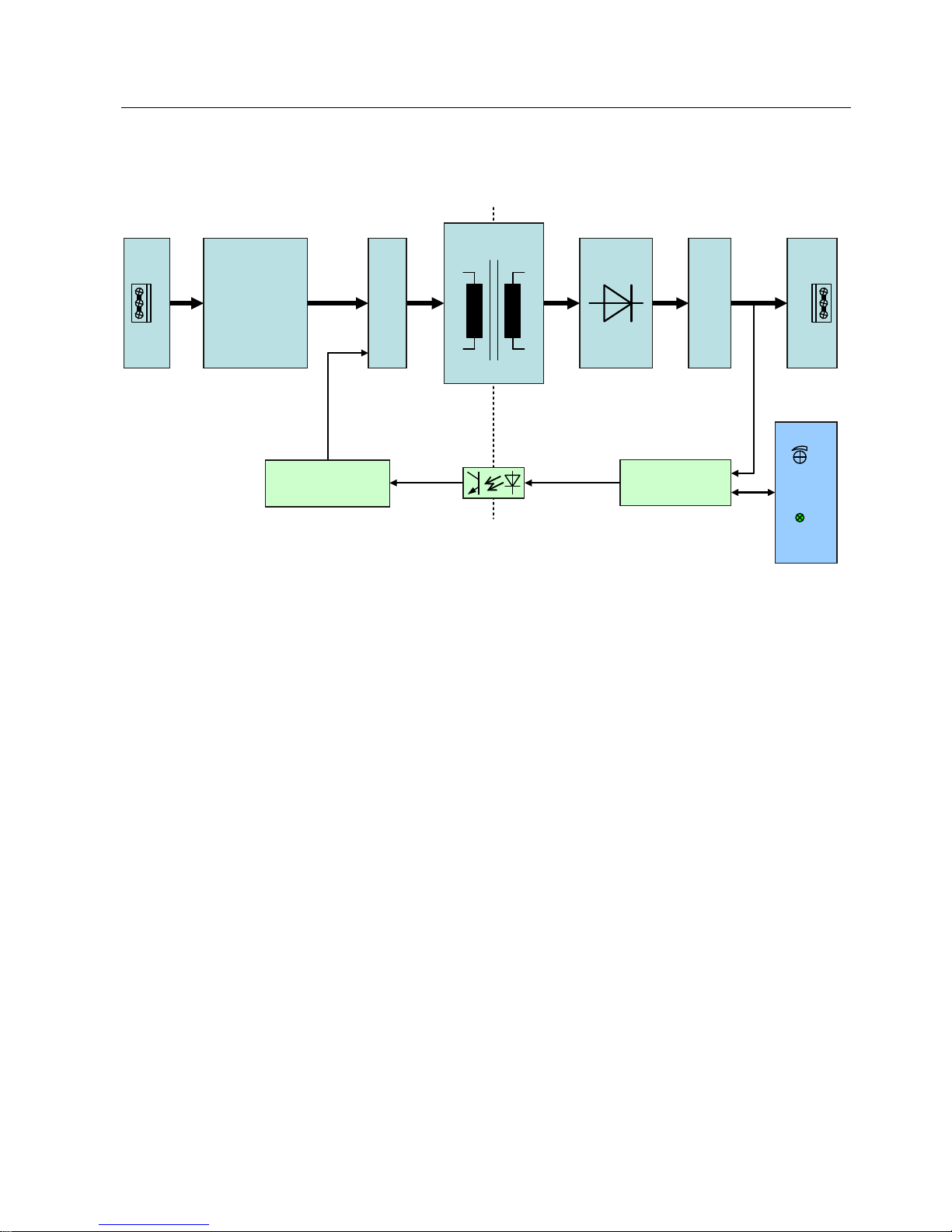
2.5 Block diagram
7UD Q VIRU P H U
3RZHU
WUDQVLVWRUV
3:0FRQWUROOHU
9ROW DJHF RQWU ROOHU
8VHU,QWHUIDFH
,QSXWWHUPLQDO$&
,QUXVKFXUUHQW
OLPLWHU
5HFWLILHU
)LOWHU
6HFRQGDU\
UHFWLILHU
2XWSXWILOWHU
2XWSXWWHUPLQDO'&
$'-867
2.
Figure 2-5 Block diagram
Description, device design, dimension drawing
2.6 Dimensions and weight
SITOP PSU100C
14 Operating Instructions, 06.2013, C98130-A7599-A1-2-7629
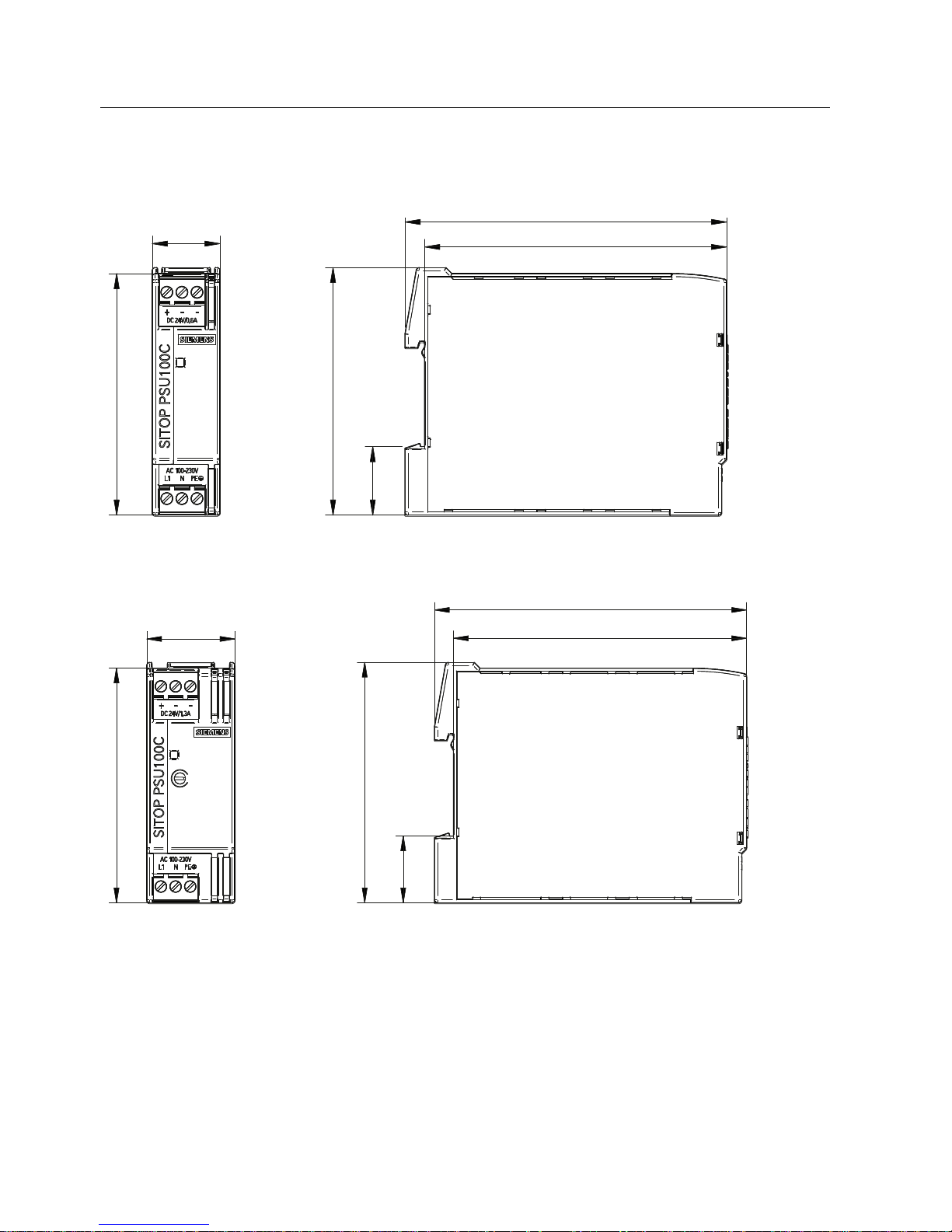
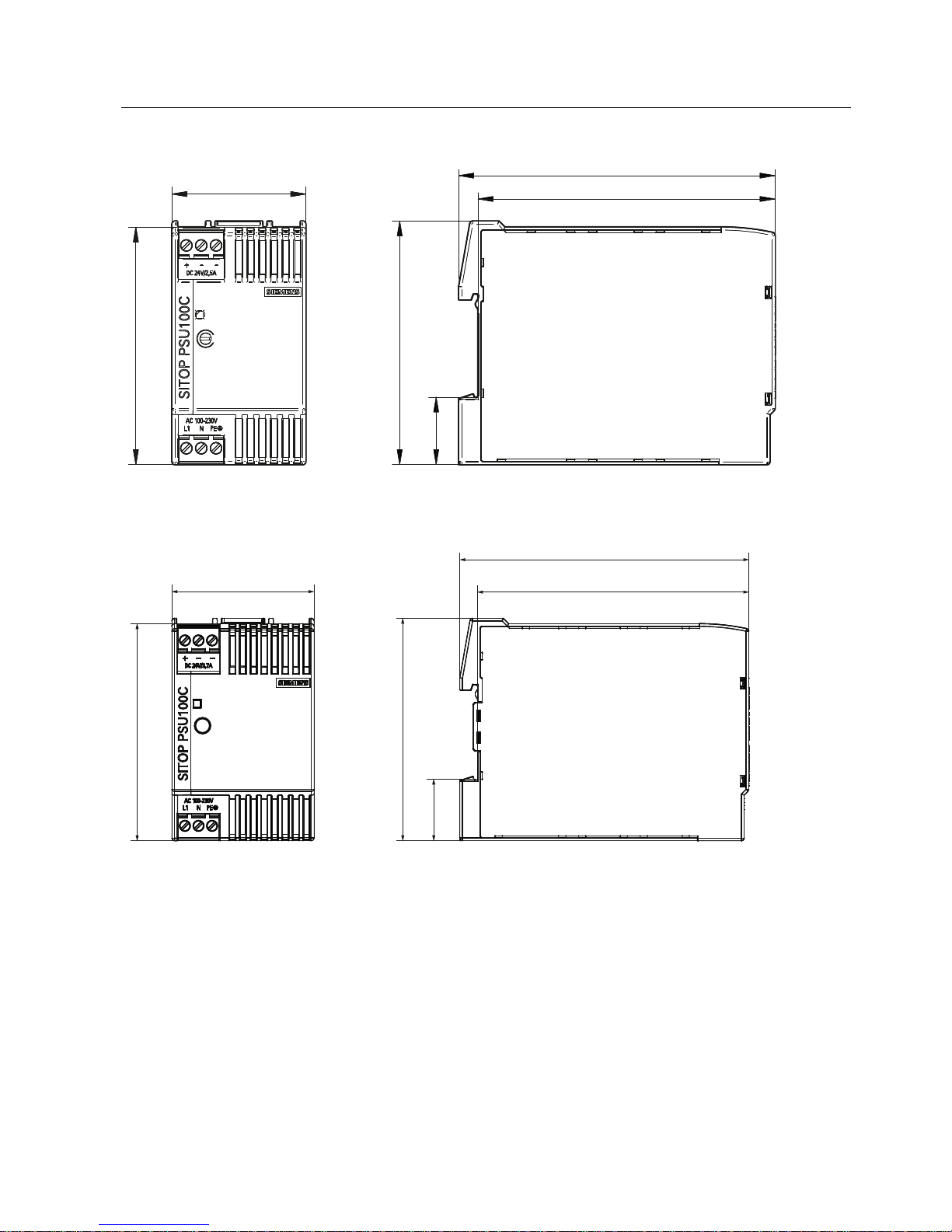
2.6 Dimensions and weight
22,5
80
82
22,7
106,5
100
Figure 2-6 Dimension drawing 6EP1331-5BA00
30
82
22,7
106,5
100
80
Figure 2-7 Dimension drawing 6EP1331-5BA10, 6EP1321-5BA00
Description, device design, dimension drawing
2.6 Dimensions and weight
SITOP PSU100C
Operating Instructions, 06.2013, C98130-A7599-A1-2-7629
15
80
45
22,7
82
100
106,5
Figure 2-8 Dimension drawing 6EP1332-5BA00
Figure 2-9 Dimension drawing 6EP1332-5BA20, 6EP1332-5BA10, 6EP1322-5BA10

Description, device design, dimension drawing
2.6 Dimensions and weight
SITOP PSU100C
16 Operating Instructions, 06.2013, C98130-A7599-A1-2-7629
6EP1331-5BA00
(24 V/0.6 A)
6EP1321-5BA00
(12 V/2 A)
6EP1331-5BA10
(24 V/1.3 A)
6EP1332-5BA00
(24 V/2.5 A)
6EP1322-5BA10
(12 V/6.5 A)
6EP1332-5BA20
(24 V/3.7 A)
6EP1332-5BA10
(24 V/4 A)
Dimensions
(W × H × D) in mm
22.5 × 80 × 100 30 × 80 × 100 45 × 80 × 100 52.5 × 80 × 100
Weight Approx. 0.12 kg Approx. 0.17 kg Approx. 0.22 kg Approx. 0.32 kg
SITOP PSU100C
Operating Instructions, 06.2013, C98130-A7599-A1-2-7629
17
Mounting/disassembly
3
WARNING
Installing the device in a housing or a control cabinet
SITOP PSU100C power supplies are built-in units. They must be installed in a casing or
control cabinet to which only qualified personnel have access.
The devices can be mounted in a control cabinet on standard mounting rails according to
EN 60715 35x7,5/15.
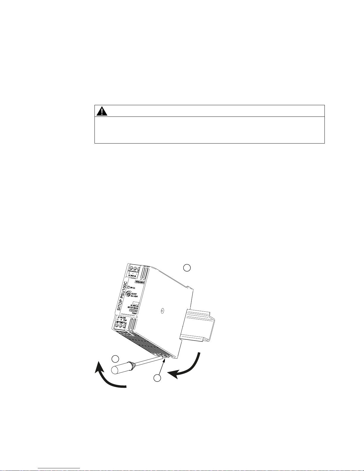
Mounting
To mount the device, position it with the mounting rail guide at the upper edge of the
standard mounting rail and press down to lock it into place. If this is too difficult, press slider
① or lug ② at the same time, as described for "Removing".
Removing
To remove, press slider
① by hand downwards, or pull the lug ② using a screwdriver ③ –
and withdraw the device at the lower edge of the standard mounting rail. Then you can
remove the device from the upper edge of the DIN rail.
ჷ
Figure 3-1 Mounting (example: 6EP1331-5BA10)
 Loading...