

Siemens SITOP PSU8600, SITOP CNX8600, SITOP BUF8600 User Manual

PSU8600power supply systems
___________________
___________________
___________________
___________________
___________________
___________________
___________________
___________________
___________________
___________________
___________________
___________________
___________________
___________________
___________________
SITOP Power Supplies
PSU8600power supply systems
Manual
SITOP PSU8600 24 V DC/20 A/4 x 5 A
6EP3436
SITOP PSU8600 24 V DC/40 A/4 x 10 A
6EP3437
SITOP CNX8600 4 x 5 A
6EP4436
SITOP CNX8600 4 x 10 A
6EP4437
SITOP BUF8600 100 ms/40 A
6EP4297
SITOP BUF8600 300 ms/40 A
6EP4297
SITOP BUF8600 4 s/40 A
6EP4293
SITOP BUF8600 10 s/40 A
6EP4295
04.2016
A5E35883207
Overview
Safety instructions
1
Description, device design,
dimension drawing
2
Operator control at the
device
3
Installation and maintenance
4
Mounting position, mounting
clearances
5
Installation
6
Engineering and remote
access
7
Troubleshooting
8
Technical data
9
Safety, approvals, EMC
10
Environmental conditions
11
Applications
12
Environment
13
Service & support
14
-8MB00-2CY0
-8MB00-2CY0
-8XB00-0CY0
-8XB00-0CY0
-8HB00-0XY0
-8HB10-0XY0
-8HB00-0XY0
-8HB00-0XY0
-7-76

Siemens AG
Division Process Industries and Drives
Postfach 48 48
90026 NÜRNBERG
GERMANY
A5E35883207-7-76
Ⓟ
Copyright © Siemens AG 2016.
All rights reserved
Legal information
Warning notice system
DANGER
indicates that death or severe personal injury will result if proper precautions are not taken.
WARNING
indicates that death or severe personal injury may result if proper precautions are not taken.
CAUTION
indicates that minor personal injury can result if proper precautions are not taken.
NOTICE
indicates that property damage can result if proper precautions are not taken.
Qualified Personnel
personnel qualified
Proper use of Siemens products
WARNING
Siemens products may only be used for the applications described in the catalog and in the relevant technical
maintenance are required to ensure that the products operate safely and without any problems. The permissible
ambient conditions must be complied with. The information in the relevant documentation must be observed.
Trademarks
Disclaimer of Liability
This manual contains notices you have to observe in order to ensure your personal safety, as well as to prevent
damage to property. The notices referring to your personal safety are highlighted in the manual by a safety alert
symbol, notices referring only to property damage have no safety alert symbol. These notices shown below are
graded according to the degree of danger.
If more than one degree of danger is present, the warning notice representing the highest degree of danger will
be used. A notice warning of injury to persons with a safety alert symbol may also include a warning relating to
property damage.
The product/system described in this documentation may be operated only by
task in accordance with the relevant documentation, in particular its warning notices and safety instructions.
Qualified personnel are those who, based on their training and experience, are capable of identifying risks and
avoiding potential hazards when working with these products/systems.
Note the following:
documentation. If products and components from other manufacturers are used, these must be recommended
or approved by Siemens. Proper transport, storage, installation, assembly, commissioning, operation and
All names identified by ® are registered trademarks of Siemens AG. The remaining trademarks in this publication
may be trademarks whose use by third parties for their own purposes could violate the rights of the owner.
We have reviewed the contents of this publication to ensure consistency with the hardware and software
described. Since variance cannot be precluded entirely, we cannot guarantee full consistency. However, the
information in this publication is reviewed regularly and any necessary corrections are included in subsequent
editions.
for the specific
04/2016 Subject to change
Overview
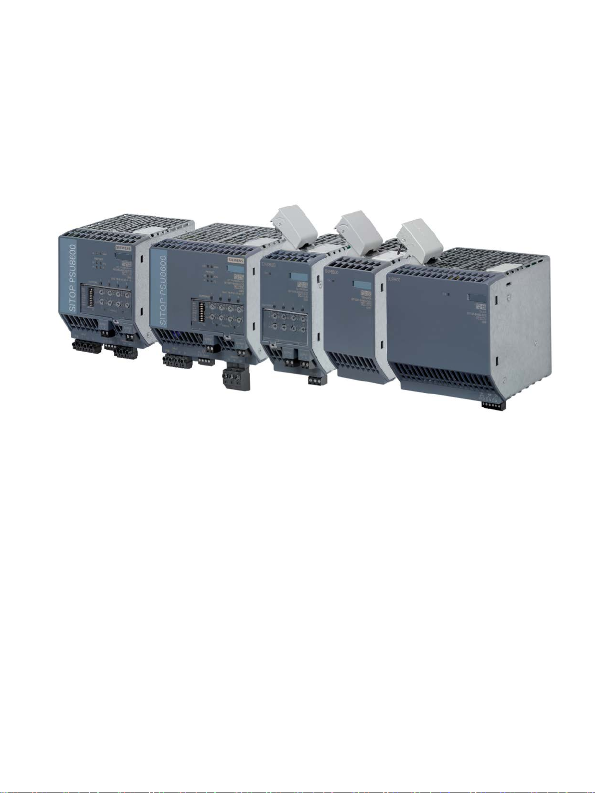
The SITOP PSU8600 power supply system is the high-performance, regulated technology
power supply system for automated plants and machines.
The key benefits of the product include:
● Wide-range input, which allows them to be connected to almost all 3-phase line supplies
around the world
● Four outputs integrated in the basic devices. Number of outputs can be expanded using
up to four expansion modules SITOP CNX8600
● The voltage of each output can be adjusted in the range 5 - 28 V
● Electronic overload shutdown for each output, the response threshold can be adjusted
● Integrated Ethernet/PROFINET interfaces (2 port switch)
● Diagnostics data and alarm messages available via Ethernet/PROFINET
● Outputs can be switched – controlled from a program – and parameterized via
Ethernet/PROFINET
● Completely integrated in TIA: User-friendly engineering in the TIA Portal, S7 function
blocks for integration in user programs and WinCC faceplates
● Remote monitoring via the integrated web server
● Brief overload capability of 150% for 5 s/min (extra power)
● Low width and high efficiency
PSU8600power supply systems
Manual, 04.2016, A5E35883207-7-76
3

Overview
Ordering data
SITOP PSU8600 power supply systems
Type
Article No.
Basic device SITOP PSU8600
Expansion modules SITOP CNX8600
4 × 10 A expansion module
6EP4437-8XB00-0CY0
Buffer modules SITOP BUF8600
10 s/40 A buffer module
6EP4295-8HB00-0XY0
Validity
● Rail mounting and connection using plug-in terminals
● To increase the plant and system availability, can be expanded using SITOP BUF8600
buffer modules and SITOP DC-UPS modules
Basic devices and supplementary modules:
3AC 400 - 500 V input
24 V/20 A/4 × 5 A output
24 V/40 A/4 × 10 A output
4 × 5 A expansion module
100 ms/40 A buffer module
300 ms/40 A buffer module
4 s/40 A buffer module
6EP3436-8MB00-2CY0
6EP3437-8MB00-2CY0
6EP4436-8XB00-0CY0
6EP4297-8HB00-0XY0
6EP4297-8HB10-0XY0
6EP4293-8HB00-0XY0
This manual provides information on the following products:
● Basic device SITOP PSU8600 24 V DC/20 A/4 × 5 A PN
Article number: 6EP3436-8MB00-2CY0
Product state: 1
Firmware version: V1.1
First release
● Basic device SITOP PSU8600 24 V DC/40 A/4 × 10 A PN
Article number: 6EP3437-8MB00-2CY0
Product state: 2
Firmware version: V1.1
Functional expansion with respect to the previous version:
– Output voltage adjustment range 5 - 28 V
– Web server is directly enabled at the device using a DIP switch
– Up to four CNX8600 expansion modules are supported
– Buffer modules BUF8600 4 s/40 A and 10 s/40 A are supported
PSU8600power supply systems
4 Manual, 04.2016, A5E35883207-7-76

Overview
● Expansion module SITOP CNX8600 4 × 5 A
Article number: 6EP4436-8XB00-0CY0
Product state: 2
Firmware version: V1.1
Functional expansion with respect to the previous version:
– Output voltage adjustment range 5 - 28 V
● Expansion module SITOP CNX8600 4 × 10 A
Article number: 6EP4437-8XB00-0CY0
Product state: 2
Firmware version: V1.1
Functional expansion with respect to the previous version:
– Output voltage adjustment range 5 - 28 V
● Buffer module SITOP BUF8600 100 ms/40 A
Article number: 6EP4297-8HB00-0XY0
Product state: 1
Firmware version: V1.1
Functional expansion with respect to the previous version:
– Buffer operation can be activated/deactivated via a remote command
● Buffer module SITOP BUF8600 300 ms/40 A
Article number: 6EP4297-8HB10-0XY0
Product state: 1
Firmware version: V1.1
Functional expansion with respect to the previous version:
– Buffer operation can be activated/deactivated via a remote command
● Buffer module SITOP BUF8600 4 s/40 A
Article number: 6EP4293-8HB00-0XY0
Product state: 1
Firmware version: V1.1
First release
● Buffer module SITOP BUF8600 10 s/40 A
Article number: 6EP4295-8HB00-0XY0
Product state: 1
Firmware version: V1.1
First release
PSU8600power supply systems
Manual, 04.2016, A5E35883207-7-76
5

Overview
PSU8600power supply systems
6 Manual, 04.2016, A5E35883207-7-76

Table of contents
Overview................................................................................................................................................. 3
1 Safety instructions ................................................................................................................................. 11
2 Description, device design, dimension drawing...................................................................................... 13
3 Operator control at the device ............................................................................................................... 51
2.1 Description of the basic devices ............................................................................................. 13
2.2 Description of the expansion modules .................................................................................... 15
2.3 Description of the buffer modules ........................................................................................... 16
2.4 Connections and terminal designations .................................................................................. 21
2.4.1 Basic devices .......................................................................................................................... 21
2.4.2 Expansion modules ................................................................................................................. 23
2.4.3 Buffer modules ........................................................................................................................ 24
2.5 Operator controls .................................................................................................................... 25
2.5.1 Basic devices .......................................................................................................................... 25
2.5.2 Expansion modules ................................................................................................................. 27
2.6 Displays .................................................................................................................................. 29
2.6.1 Basic devices .......................................................................................................................... 29
2.6.2 Expansion modules ................................................................................................................. 33
2.6.3 Buffer modules ........................................................................................................................ 35
2.7 Signaling contact/control contact ............................................................................................ 37
2.7.1 Basic devices .......................................................................................................................... 37
2.7.2 Buffer modules ........................................................................................................................ 38
2.8 Block diagrams ....................................................................................................................... 40
2.9 Dimensions and weights ......................................................................................................... 42
3.1 Setting the output voltage and response threshold value of the output current ..................... 53
3.1.1 Setting the output voltage ....................................................................................................... 53
3.1.2 Setting the response threshold value of the output current .................................................... 54
3.2 Switching-in and switching-out outputs ................................................................................... 55
3.3 Overload shutdown and carrying out a reset .......................................................................... 56
3.4 MANUAL and REMOTE operating modes.............................................................................. 59
3.5 Prioritization when the power fails .......................................................................................... 62
3.6 ELECTRONIC SHUTDOWN and CONSTANT CURRENT operating modes ........................ 64
3.7 Setting the on delay ................................................................................................................ 66
3.8 Connecting outputs of the basic unit in parallel ...................................................................... 69
3.9 Activating the web server on the module ................................................................................ 72
3.10 Monitoring functions ................................................................................................................ 74
PSU8600power supply systems
Manual, 04.2016, A5E35883207-7-76
7

Table of contents
4 Installation and maintenance ................................................................................................................. 81
5 Mounting position, mounting clearances ................................................................................................ 97
6 Installation ........................................................................................................................................... 107
7 Engineering and remote access ........................................................................................................... 117
3.10.1 Overtemperature monitoring functions .................................................................................. 74
3.10.2 Phase dissymmetry monitoring .............................................................................................. 76
3.10.3 System overload monitoring .................................................................................................. 77
3.11 Activating and deactivating buffer operation .......................................................................... 80
4.1 Connecting plug ..................................................................................................................... 81
4.2 Rail mounting ......................................................................................................................... 82
4.3 Permissible hardware configurations ..................................................................................... 84
4.4 Removal ................................................................................................................................. 85
4.5 Replacing individual components .......................................................................................... 87
4.6 System response for a modified hardware configuration....................................................... 91
4.6.1 Response after changing an individual component ............................................................... 92
4.6.2 Response after adding an individual component ................................................................... 94
4.6.3 Response after removing an individual component ............................................................... 94
5.1 Standard mounting position ................................................................................................... 97
5.2 Other mounting positions ....................................................................................................... 99
5.2.1 SITOP PSU8600 4 x 5 A basic device ................................................................................... 99
5.2.2 SITOP PSU8600 4 x 5 A basic device and supplementary modules .................................. 101
5.2.3 SITOP PSU8600 4 x 10 A basic device ............................................................................... 103
5.2.4 SITOP PSU8600 4 x 10 A basic device and supplementary modules ................................ 105
6.1 Line-side connection ............................................................................................................ 107
6.2 Output-side connection ........................................................................................................ 109
6.3 Connecting the signaling contact/reset terminal .................................................................. 111
6.4 Establishing a PROFINET connection ................................................................................. 113
6.5 Establishing an additional ground connection ..................................................................... 114
6.6 Connecting the control contact and signaling contacts of the buffer module ...................... 115
7.1 General information ............................................................................................................. 117
7.2 Overview of application examples ....................................................................................... 117
7.3 SIMATIC STEP 7 in the TIA Portal ...................................................................................... 118
7.3.1 Installing the Hardware Support Package (HSP) ................................................................. 118
7.3.2 Geräte-Stammdaten-Datei (GSD) installieren ..................................................................... 119
7.3.3 Inserting SITOP PSU8600 into a project ............................................................................. 120
7.3.4 Assigning a SITOP PSU8600 to a controller ....................................................................... 122
7.3.5 Assigning supplementary modules to the SITOP PSU8600 basic device ........................... 123
7.3.6 Parameter assignment ......................................................................................................... 127
7.3.6.1 Parameters of the basic units and the supplementary modules .......................................... 127
7.3.6.2 Parameterizing the basic unit ............................................................................................... 130
7.3.6.3 Parameterizing outputs ........................................................................................................ 136
PSU8600power supply systems
8 Manual, 04.2016, A5E35883207-7-76

Table of contents
8 Troubleshooting .................................................................................................................................. 223
9 Technical data .................................................................................................................................... 227
7.3.7 Loading the configuration (commissioning) .......................................................................... 137
7.3.8 Diagnostics ........................................................................................................................... 141
7.3.9 Firmware update ................................................................................................................... 142
7.3.10 Reset to factory settings ....................................................................................................... 143
7.4 SIMATIC STEP 7 .................................................................................................................. 144
7.4.1 Installing the device data file (GSD) ..................................................................................... 144
7.4.2 Inserting SITOP PSU8600 into a project .............................................................................. 145
7.4.3 Assigning supplementary modules to the basic unit ............................................................. 148
7.4.4 Parameter assignment .......................................................................................................... 151
7.4.4.1 Parameterizing SITOP PSU8600 ......................................................................................... 151
7.4.4.2 Parameters of the basic unit and supplementary modules ................................................... 152
7.4.4.3 Parameterizing the basic unit ............................................................................................... 154
7.4.4.4 Parameterizing outputs ......................................................................................................... 159
7.4.5 Loading the configuration (commissioning) .......................................................................... 161
7.4.6 Diagnostics ........................................................................................................................... 162
7.4.7 Firmware update ................................................................................................................... 163
7.4.8 Reset to factory settings ....................................................................................................... 163
7.5 Web server ............................................................................................................................ 165
7.5.1 Accessing the web server ..................................................................................................... 165
7.5.2 The web server user interface .............................................................................................. 167
7.5.3 Functions of the web server .................................................................................................. 168
7.5.4 Loading the configuration (commissioning) .......................................................................... 170
7.5.5 Diagnostics ........................................................................................................................... 170
7.5.5.1 Alarms ...................................................................................................................................
170
7.5.5.2 Operating data ...................................................................................................................... 172
7.5.5.3 Online functions .................................................................................................................... 173
7.5.6 HW configuration .................................................................................................................. 177
7.5.6.1 Configuring the PROFINET interface ................................................................................... 179
7.5.6.2 Web server settings / user administration............................................................................. 180
7.5.6.3 Configuring SITOP PSU8600 ............................................................................................... 183
7.5.6.4 Loading and saving configurations ....................................................................................... 191
7.6 Cyclic and acyclic data.......................................................................................................... 192
7.6.1 Input and output data ............................................................................................................ 193
7.6.1.1 Input data .............................................................................................................................. 193
7.6.1.2 Output data ........................................................................................................................... 195
7.6.1.3 Operating states SITOP PSU8600 ....................................................................................... 198
7.6.1.4 Operating states SITOP CNX8600 ....................................................................................... 199
7.6.1.5 Operating states SITOP BUF8600 ....................................................................................... 200
7.6.2 Reading and writing data sets .............................................................................................. 201
7.6.2.1 Overview of reading and writing data sets ............................................................................ 201
7.6.2.2 Data sets SITOP PSU8600 .................................................................................................. 203
7.6.2.3 Data sets SITOP CNX8600 .................................................................................................. 213
7.6.2.4 Data sets SITOP BUF8600 ................................................................................................... 218
8.1 Troubleshooting based on the LED signal sequence ........................................................... 223
8.2 PROFINET alarm list ............................................................................................................ 223
9.1 Input data .............................................................................................................................. 227
PSU8600power supply systems
Manual, 04.2016, A5E35883207-7-76
9

Table of contents
10 Safety, approvals, EMC ....................................................................................................................... 241
11 Environmental conditions ..................................................................................................................... 245
12 Applications ......................................................................................................................................... 247
13 Environment ........................................................................................................................................ 249
14 Service & support................................................................................................................................. 251
9.2 Output data .......................................................................................................................... 228
9.3 Efficiency .............................................................................................................................. 234
9.4 Closed-loop control .............................................................................................................. 235
9.5 Protection and monitoring .................................................................................................... 235
9.6 MTBF ................................................................................................................................... 236
9.7 Mechanical system .............................................................................................................. 237
9.8 Accessories .......................................................................................................................... 239
9.9 Dimension drawings ............................................................................................................. 239
10.1 Safety ................................................................................................................................... 241
10.2 Test voltages ........................................................................................................................ 242
10.3 Approvals ............................................................................................................................. 243
10.4 EMC ..................................................................................................................................... 244
12.1 Protection against brief power failures ................................................................................. 247
12.2 Protecting against longer power failures .............................................................................. 248
PSU8600power supply systems
10 Manual, 04.2016, A5E35883207-7-76

1
WARNING
Correct handling of the devices
When operating electrical devices, it is inevitable that certain components will carry
dangerous voltages.
Therefore, failure to handle the units properly can result in death or serious physical injury
as well as extensive property damage.
Only appropriately qualified personnel may work on or in the vicinity of this equipment.
Perfect, safe, and reliable operation of this equipment is dependent on proper
transportation, storage, installation and mounting.
Before installation or maintenance work can begin, the system's main switch must be
switched off and measures taken to prevent it being switched on again.
If this instruction is not observed, touching live parts can result in death or serious injury.
Siemens provides products and solutions with industrial security functions that support the
secure operation of plants, solutions, machines, equipment and/or networks. They are
important components in a holistic industrial security concept. With this in mind, Siemens’
products and solutions undergo continuous development. Siemens recommends strongly
that you regularly check for product updates.
For the secure operation of Siemens products and solutions, it is necessary to take suitable
preventive action (e.g. cell protection concept) and integrate each component into a holistic,
state-of-the-art industrial security concept. Third-party products that may be in use should
also be considered. You can find more information about industrial security under:
http://www.siemens.com/industrialsecurity
To stay informed about product updates as they occur, sign up for a product-specific
newsletter. You can find additional information on this at:
http://support.automation.siemens.com.
PSU8600power supply systems
Manual, 04.2016, A5E35883207-7-76
11

Safety instructions
PSU8600power supply systems
12 Manual, 04.2016, A5E35883207-7-76

2
2.1
Description of the basic devices
Designation
Number of outputs
Max. current per output
Article No.
24 V/20 A/4 × 5 A DC
4 5 A 6EP3436-8MB00-2CY0
24 V/40 A/4 × 10 A DC
4 10 A
6EP3437-8MB00-2CY0
The basic devices SITOP PSU8600 are primary-clocked power supplies for connection to 3phase AC line supplies. Electronically regulated DC voltages are available at the outputs of
the devices. The DC voltage at each output can be individually adjusted using a
potentiometer. The device outputs are isolated, no-load and short-circuit proof and have an
electronic overload trip, which can be set for each output using an additional potentiometer.
Each of the device outputs can be individually switched-on and switched-off using a button.
LEDs signal the operating state of the devices as well as the individual outputs. The
electronic overload shutdown is reset using the reset input and the buttons of the outputs.
Additional, special functions of the devices can be activated using selector (DIP) switches.
The outputs of the devices can be controlled, operating and diagnostics data transferred and
externally visualized or processed via the two integrated industrial Ethernet/PROFINET
ports. An integrated web server allows authorized users to read and write data remotely via a
web browser.
The functionality of the basic devices can be expanded using supplementary modules. There
are expansion modules to increase the number of outputs, and buffer modules to extend the
internal device power failure buffer time.
Table 2- 1 Versions of the basic device
Power supply
Power supply
PSU8600power supply systems
Manual, 04.2016, A5E35883207-7-76
13
Description, device design, dimension drawing
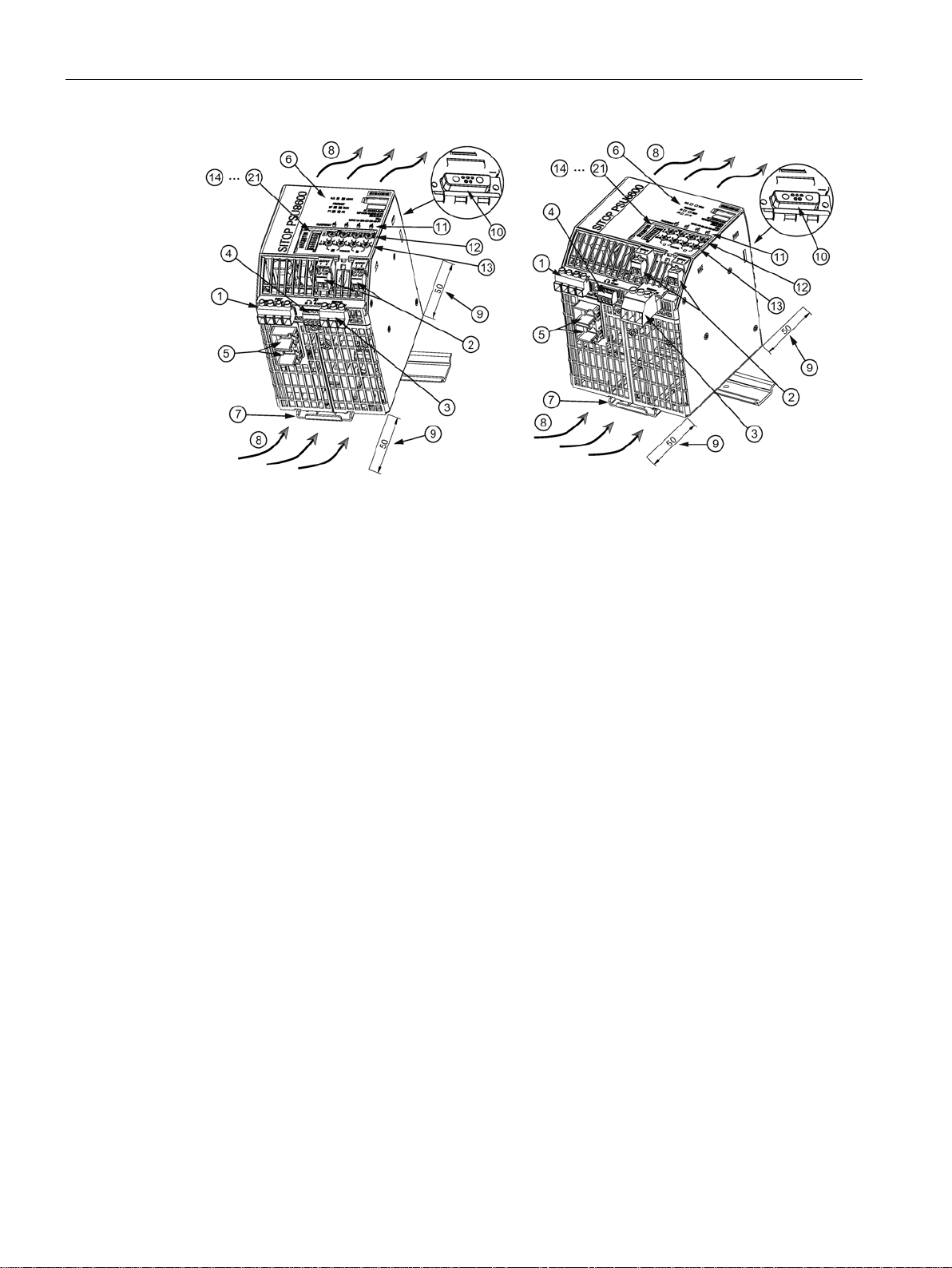
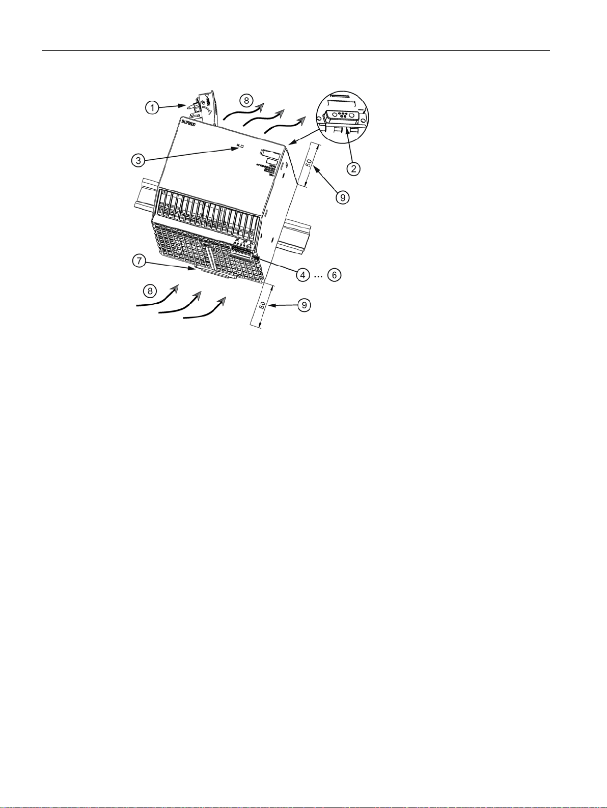
①
AC input
②
DC outputs
③
0 Volt terminal
④
Signaling contact, remote reset
⑤
Ethernet/PROFINET interface
⑥
LEDs (OK, MAN, SF, RUN, P1/P2)
⑦
DIN rail slider
⑧
Convection
⑨
Clearance above/below
⑩
ules
⑪
Buttons of the outputs with LEDs "ON/OFF/RST"
⑫
Voltage potentiometer
⑬
Current potentiometer
from ⑭
Selector switch, special functions
2.1 Description of the basic devices
Socket at the upper side of the device for the plug connection to optional expansion mod-
PSU8600power supply systems
14 Manual, 04.2016, A5E35883207-7-76
Description, device design, dimension drawing
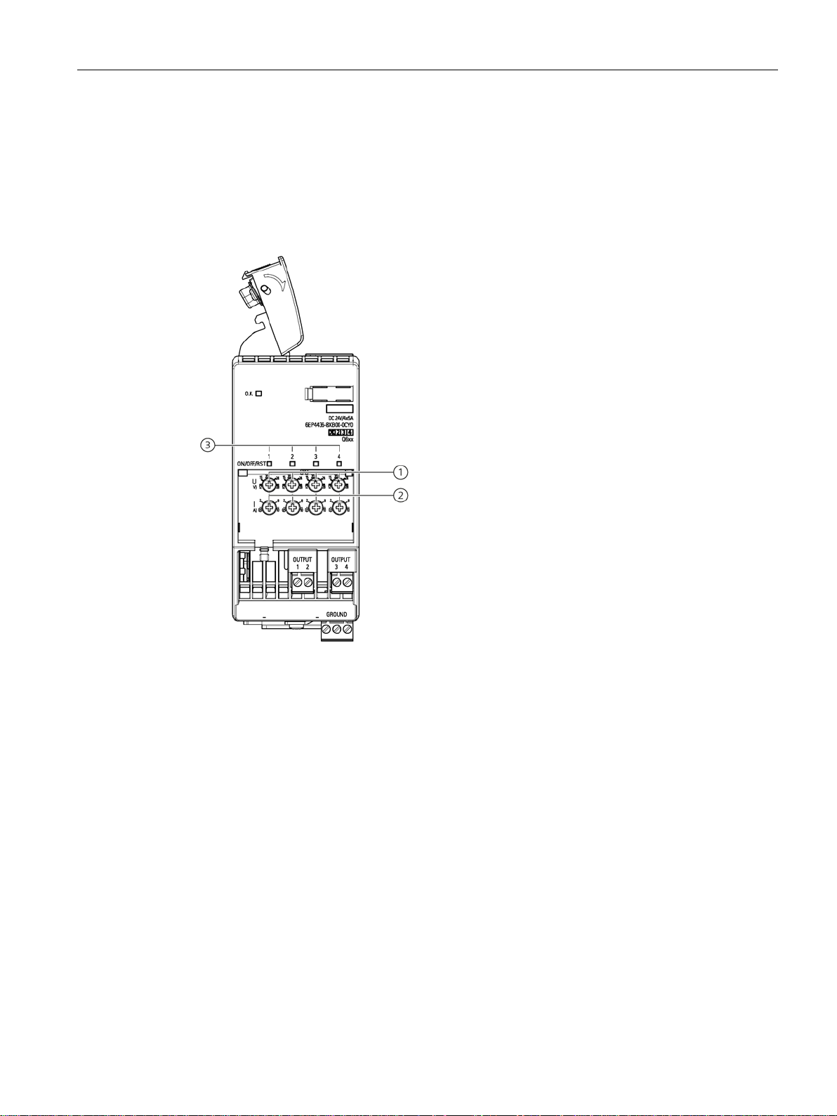
2.2
Description of the expansion modules
Expansion module versions
Designation
Number of outputs
Max. current per output
Article No.
4 × 5 A expansion module
4
5 A
6EP4436-8XB00-0CY0
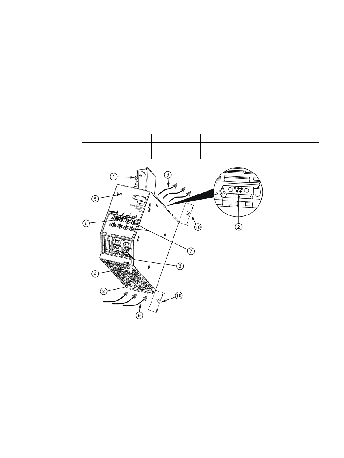
①
additional modules
②
Socket at the upper side of the device for the plug connection to additional modules
③
DC outputs
④
Ground connection
⑤
"OK" LED display
⑥
Buttons of the outputs with LEDs "ON/OFF/RST"
⑦
Voltage, current potentiometer
⑧
DIN rail slider
⑨
Convection
⑩
Clearance above/below
2.2 Description of the expansion modules
Using a SITOP CNX8600 expansion module, the number of system outputs can be
increased, however, not the maximum output power of the basic device. The expansion
modules have, just like the basic device, a potentiometer for setting, and buttons to switchon and switch-off the relevant output. LEDs signal the operating states of the expansion
module as well as the individual outputs. A maximum of four expansion modules can be
used for each basic device. The connection to the basic device or to the adjacent module is
established using an integrated connecting plug.
4 × 10 A expansion module 4 10 A 6EP4437-8XB00-0CY0
Connecting plug at the upper side of the device for the plug connection to the basic device or
PSU8600power supply systems
Manual, 04.2016, A5E35883207-7-76
15

Description, device design, dimension drawing
2.3
Description of the buffer modules
Buffer module versions
Designation
Buffer time
Typical charge
time for a rated
input voltage of
400 V
Article No.
100 ms/40 A
2.3 Description of the buffer modules
A buffer module SITOP BUF8600 allows the buffer time to be extended when the power
fails. An LED is used to signal the operating state of the buffer module. A maximum of two
buffer modules can be used for each basic unit. The connection to the basic unit or to the
adjacent module is established using an integrated connecting plug.
For brief power failures, the outputs of the power supply system are supplied without
interruption using the energy stored in the buffer module.
There are two BUF8600 buffer module versions available. Buffer modules with electrolytic
capacitors and buffer modules with double-layer capacitors.
Table 2- 2 BUF8600 buffer modules with electrolytic capacitors
Buffer module
Buffer module
300 ms/40 A
100 ms at 40 A 20 s 6EP4297-8HB00-0XY0
300 ms at 40 A 60 s 6EP4297-8HB10-0XY0
PSU8600power supply systems
16 Manual, 04.2016, A5E35883207-7-76
Description, device design, dimension drawing
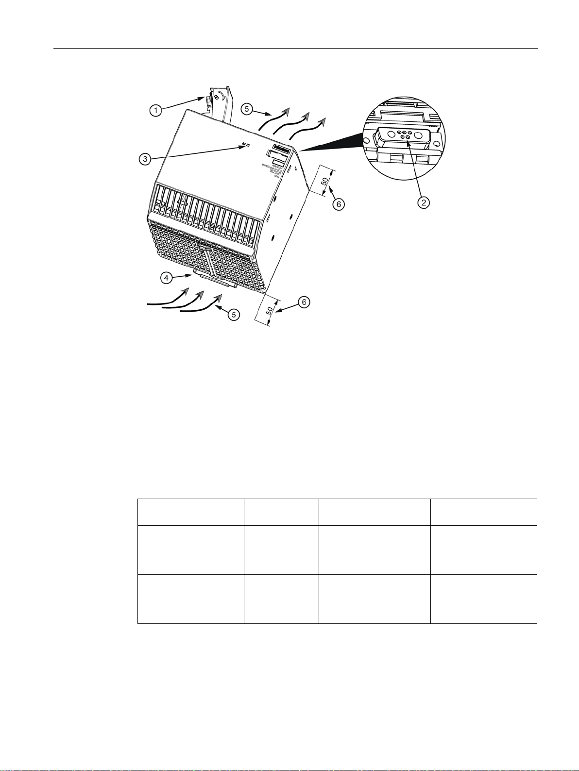
①
additional modules.
②
Socket at the upper side of the device for the plug connection to additional modules
③
"O.K." LED
④
DIN rail slider
⑤
Convection
⑥
Clearance above/below
Designation
Buffer time
Charge time for a rated
input voltage of 400 V
Article number
charged)
charged)
2.3 Description of the buffer modules
Connecting plug at the upper side of the device for the plug connection to the basic unit or
When the buffer module with electrolytic capacitors is completely charged (LED "O.K." lights
green) power failures of 100 ms or 300 ms can be buffered with a load current of 40 A. The
buffer time is correspondingly increased for lower load currents.
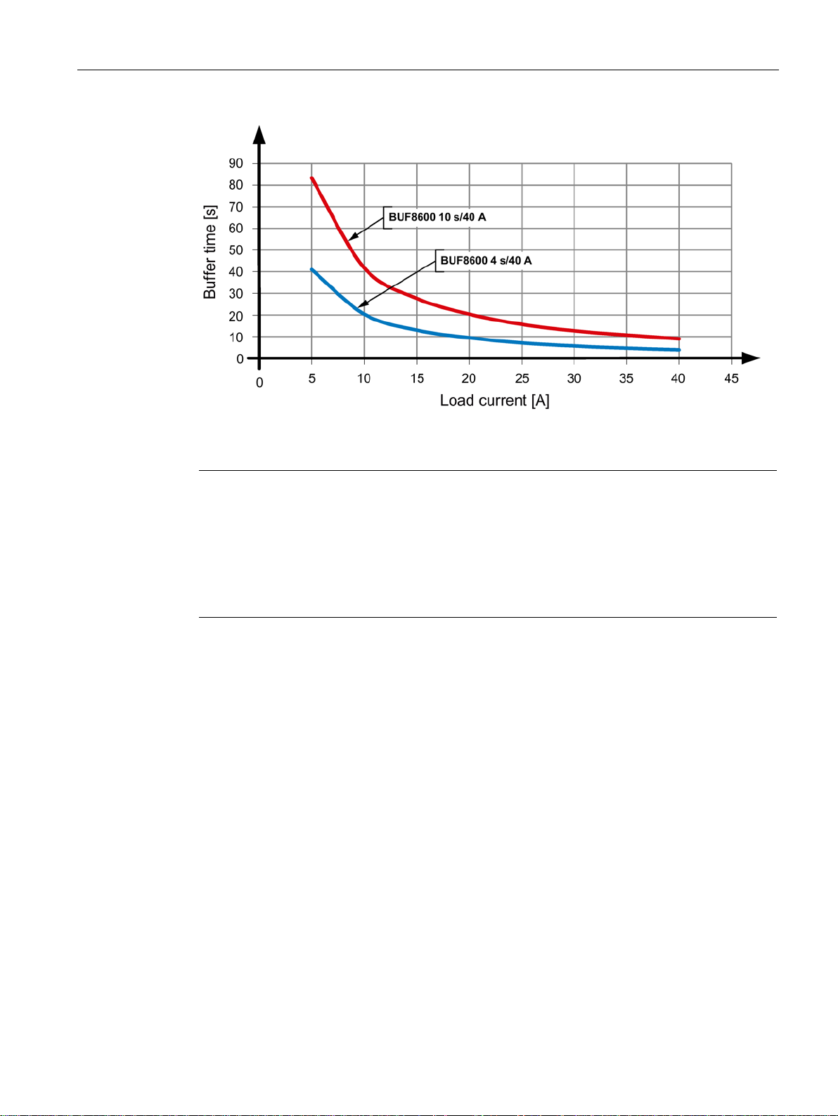
Table 2- 3 BUF8600 buffer modules with double-layer capacitors
4 s/40 A buffer module 4 s at 40 A typ. 5 min;
max. 8 min
(when completely dis-
10 s/40 A buffer module 10 s at 40 A typ. 10 min;
max. 18 min
(when completely dis-
6EP4293-8HB00-0XY0
6EP4295-8HB00-0XY0
PSU8600power supply systems
Manual, 04.2016, A5E35883207-7-76
17
Description, device design, dimension drawing
①
additional modules
②
Socket at the upper side of the device for the plug connection to additional modules
③
"O.K." LED
④
⑦
DIN rail slider
⑧
Convection
⑨
Clearance above/below
2.3 Description of the buffer modules
Connecting plug at the upper side of the device for the plug connection to the basic device or
…⑥ Remote ON/OFF and signaling contacts
When the buffer module with double-layer capacitors is completely charged (LED "O.K"
lights green) power failures of 4 s or 10 s can be buffered with a load current of 40 A. The
buffer time is correspondingly increased for lower load currents.
PSU8600power supply systems
18 Manual, 04.2016, A5E35883207-7-76
Description, device design, dimension drawing
Note
Restriction when using a SITOP BUF8600 4 s/40 A buffer module in a 40 A- power supply
system
When using a SITOP BUF8600 4
150
not
The buffer mode is immediately exited if, during the buffer mod
%
occurs.
Brief interruption of the voltage at output 1
"Longlife" mode
2.3 Description of the buffer modules
Image 2-1 Typical buffer time as a function of the load current
s/40 A buffer module in a 40 A power supply system, the
% overload capability for 5 s/min (Extra-Power) is
supported.
e, a system overload > 100
When using a buffer module with double-layer capacitors, the following additional functions
are available:
If a PC is operated on the PSU8600 power supply system, when the power fails, then this
must be run down in plenty of time before the buffer time expires in order to avoid data being
lost. If the supply voltage returns after the shutdown has already started, the buffer mode is
exited and the power supply resumes normal operation. However, the PC is run down
completely. If the PC does not have an ON/OFF-switch, then it can only be rebooted by
switching off the power supply and switching it on again.
When using a buffer module with double-layer capacitors, the "Enable short-time interruption
at output 1" function is used to activate the brief interruption of the voltage at output 1 when
the supply voltage returns. However, the selection and parameterization is only possible
when appropriately configured (web server, STEP 7).
You can find additional information in Chapter Engineering and remote access (Page 117)
In order to increase the service life of the buffer modules with a double-layer capacitors, this
can be operated in the "Longlife" mode with reduced buffer capacity. When the buffer
PSU8600power supply systems
Manual, 04.2016, A5E35883207-7-76
19

Description, device design, dimension drawing
2.3 Description of the buffer modules
module is completely charged (LED ""O.K." lights green) power failures of 3 s up to a
maximum of 8 s can be buffered with a load current of 40 A. However, the "Longlife" mode is
only possible when appropriately configured (web server, STEP 7).
You can find additional information in Chapter Engineering and remote access (Page 117)
PSU8600power supply systems
20 Manual, 04.2016, A5E35883207-7-76
Description, device design, dimension drawing
2.4
Connections and terminal designations
2.4.1
Basic devices
Connections and terminal designations
①
L1, L2, L3, PE
1, 2, 3, 4
each output
③
0 V
④
(11, 12, 14);
RST
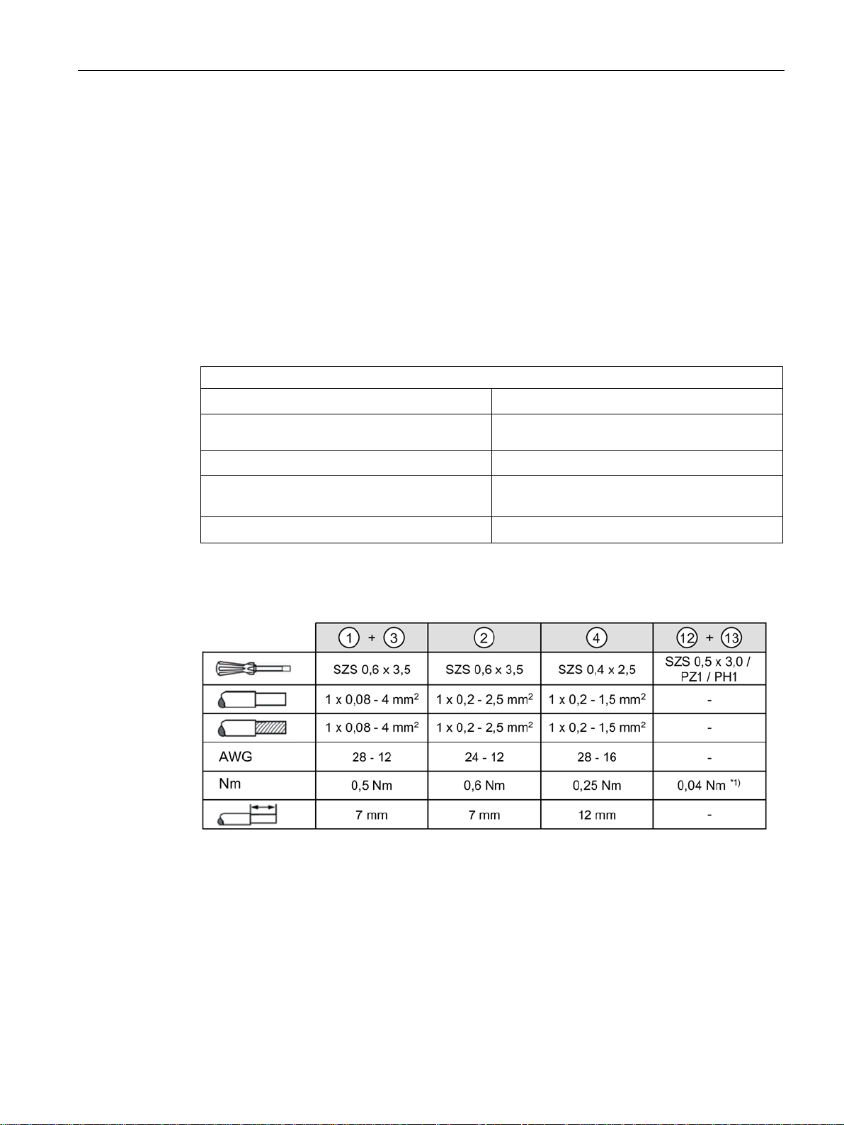
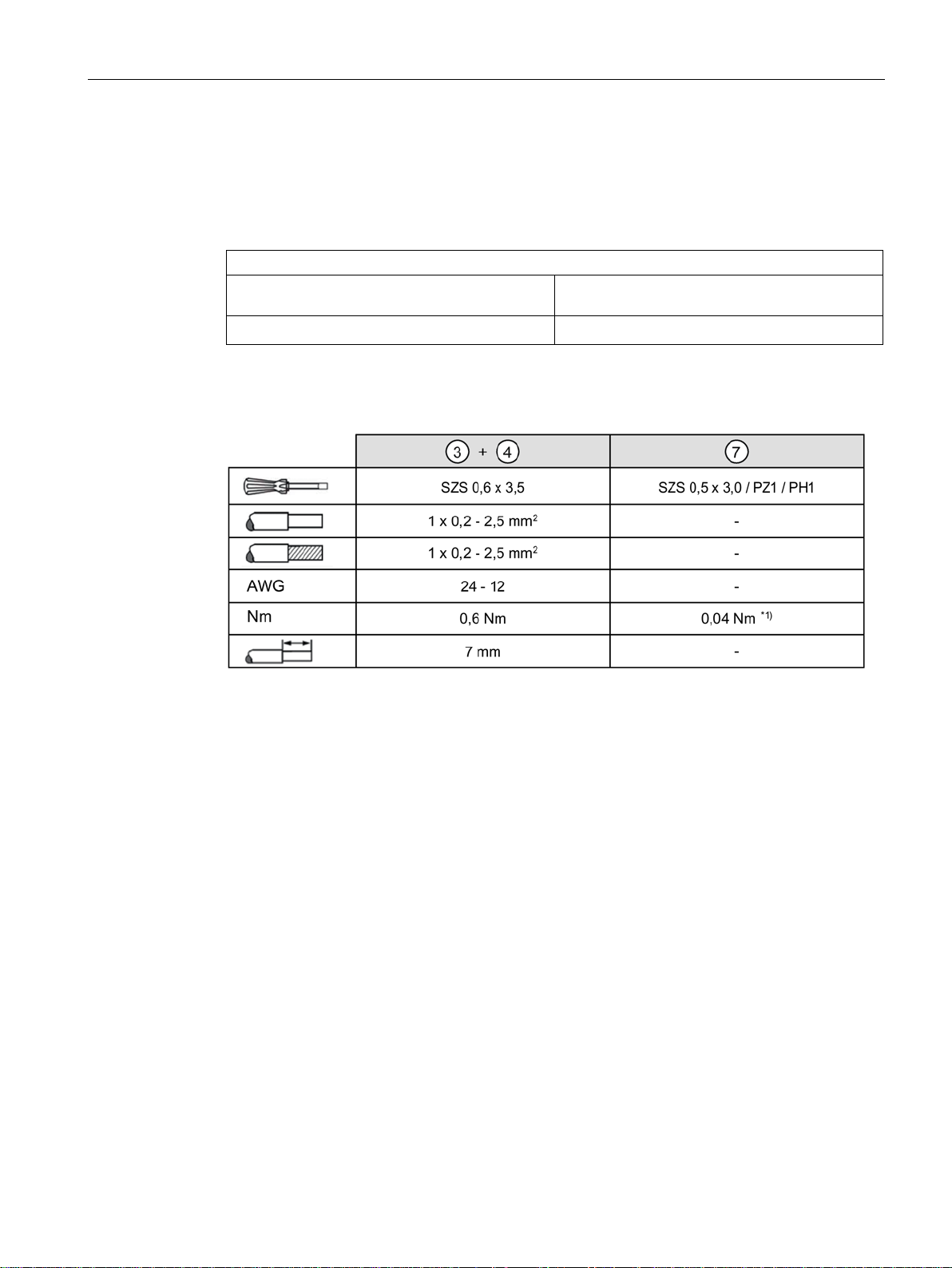
Terminal data 6EP3436-8MB00-2CY0:
*1) Do not subject the end stop to high loads
2.4 Connections and terminal designations
The line input terminals ① are used to establish the connection to the supply voltage. The
output terminals
terminal
The operating state of the device can be interrogated using signaling contact
terminal
At the Ethernet/PROFINET interface
8P8C) is connected for PROFINET operation.
③ a ground connection can be established to additional supplementary modules.
④ is used to remotely reset the electronic overload trip.
② and the 0 V terminal ③ are the load connections. Further, via the 0 Volt
④. The reset
⑤ Ethernet/PROFINET cable (RJ plug connection
Line input
② Outputs
0 Volt terminal
Signaling contact
remote reset
⑤ PROFINET (2-port switch)
See the diagram under Description of the basic devices (Page 13)
Plug-in terminal with a screw connection
Two plug-in terminals with screw connection for
Plug-in terminal with three screw connections
Common plug-in terminal with a screw connection
RJ plug connection 8P8C
PSU8600power supply systems
Manual, 04.2016, A5E35883207-7-76
21
Description, device design, dimension drawing
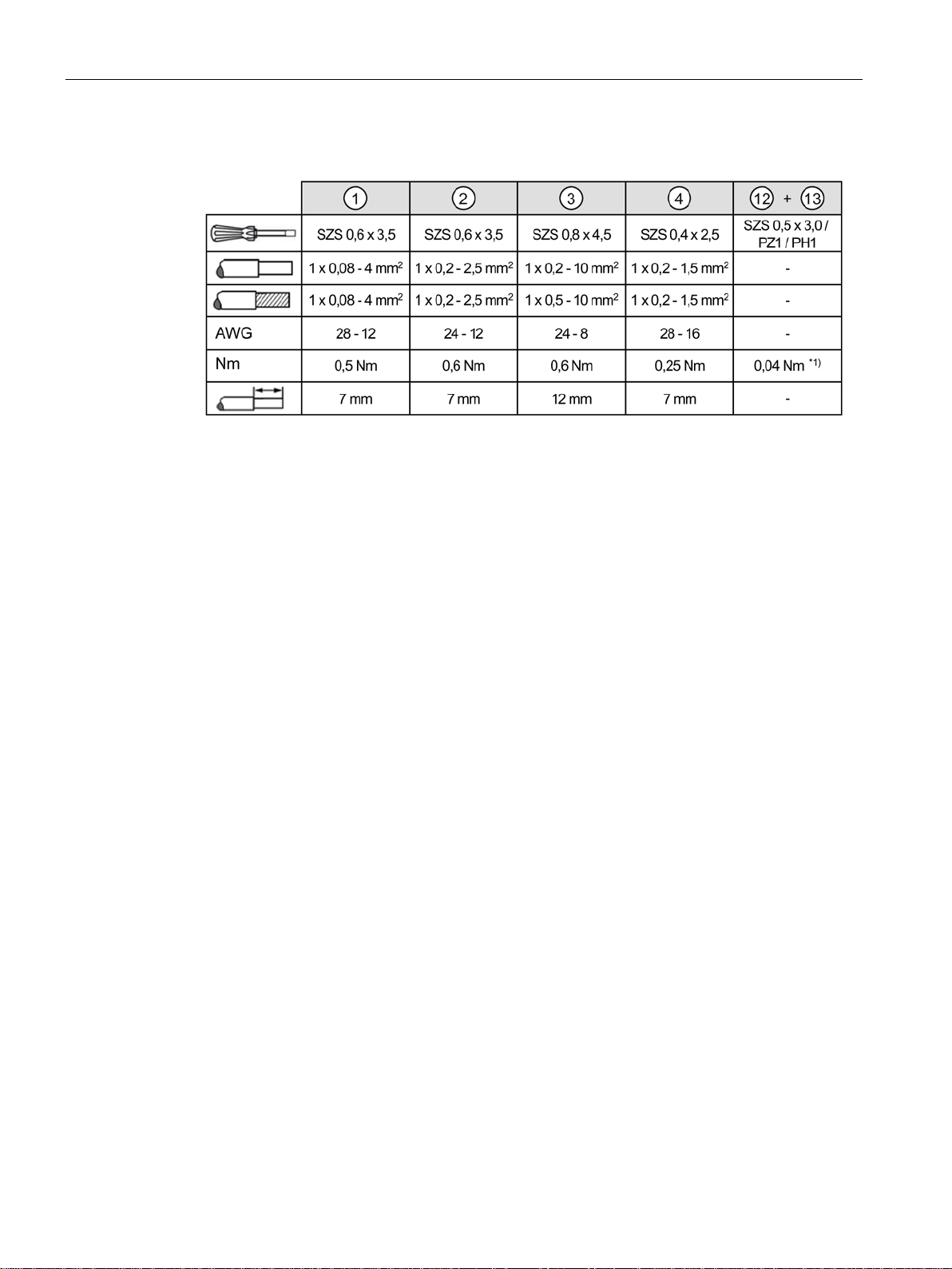
Terminal data 6EP3437-8MB00-2CY0:
*1) Do not subject the end stop to high loads
Ethernet/PROFINET connection
2.4 Connections and terminal designations
Maximum length of the Ethernet/PROFINET cable: 100 m (90 m BASIC link plus 2 x 5 m
CHANNEL link).
The interface corresponds to the standard full duplex up to 100 Mbit/s electrical (100BASETX) according to IEEE 802.3.
Properties of the interface:
● Transfer rate 10/100 Mbit/s
● Two RJ45 sockets, i.e. integrated switch, for RJ45 connector, cable type 100Base-TX
(CAT5)
● Auto negotiation
● Auto crossover communication via TCP/IP and PROFINET
The physics of the Ethernet/PROFINET interface are implemented so that PROFINET IO
according to standards IEC 61158 and IEC 61784-2 are possible. As a minimum, conformity
Class B is maintained for PROFINET.
PSU8600power supply systems
22 Manual, 04.2016, A5E35883207-7-76
Description, device design, dimension drawing
2.4.2
Expansion modules
Connections and terminal designations
1, 2, 3, 4
each output
④
GND
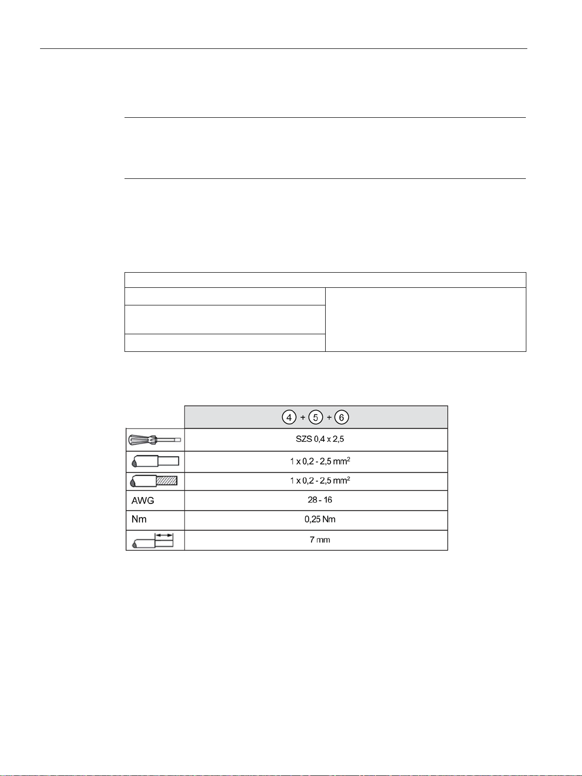
Terminal data 6EP4436-8XB00-0CY0, 6EP4437-8XB00-0CY0:
*1) Do not subject the end stop to high loads
2.4 Connections and terminal designations
The loads to be supplied are connected at output terminals ③. When required, a ground
connection to the basic device and to additional supplementary modules can be established
using ground terminal
④.
③ Outputs
Ground terminal
Two plug-in terminals with screw connection for
Plug-in terminal with three screw connections
See the diagram under Description of the expansion modules (Page 15)
PSU8600power supply systems
Manual, 04.2016, A5E35883207-7-76
23
Description, device design, dimension drawing
2.4.3
Buffer modules
Note
Terminals, only for buffer modules with double-layer capacitors
The subsequently described terminals are only available for buffer modules with double-layer
capacitors.
Connections and terminal designations
④
⑤
RDY 13, 14
④
Terminal data 6EP4293-8HB00-0XY0, 6EP4295-8HB00-0XY0:
2.5 Operator controls
Using control contact (ON), the buffer readiness of the buffer module can be activated and
deactivated and/or buffer mode exited.
Using signaling contact "Sufficient buffer readiness" (RDY) it can be interrogated as to
whether the buffer module has reached an adequate charge state. Using signaling contact
"Buffer mode" (OK) the system signals that it is currently in the buffer mode.
Control contact ON X1, X2
Signaling contact "Sufficient buffer readiness"
Signaling contact "Buffer mode" OK 23, 24
Common plug-in terminal, each with a screw
connection
See the diagram under Description of the buffer modules (Page 16)
PSU8600power supply systems
24 Manual, 04.2016, A5E35883207-7-76
Description, device design, dimension drawing
2.5
Operator controls
2.5.1
Basic devices
No.
Designation/labeling
Function
①
ter "U (V)"
and response threshold value of the output current (Page 53).
②
(Page 54).
③
out a reset (Page 56).
④
(Page 59).
⑤
fails (Page 62).
2.5 Operator controls
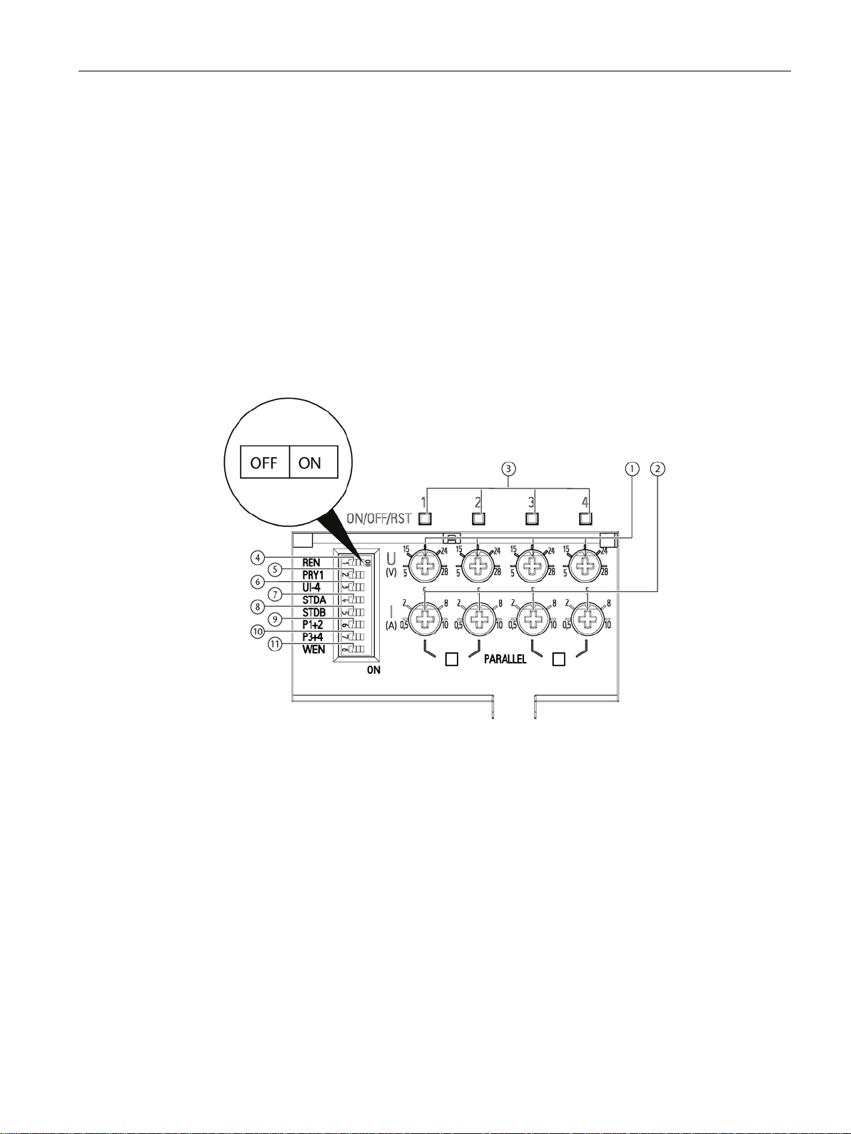
There are two main operating areas at the SITOP PSU8600 basic devices.
● Potentiometers (
The potentiometers are used to set the output voltage and the response threshold of the
output current. The potentiometers can be individually set for each output. The individual
outputs can be switched-on and switched-off using the buttons; further, each output can
be manually reset after an electronic shutdown.
● The selector switch allows additional special functions to be activated via the position of
the slider switches (
① and ②) and LED button ③:
④ to ⑪, see the magnifying glass in the diagram).
Voltage potentiome-
Current potentiome-
ter "I (A)"
LED buttons
"ON/OFF/RST"
DIP switch "REN" Switches over between the MANUAL mode – with setting and opera-
DIP switch "PRY1" Prioritizes output 1 when buffering; see Prioritization when the power
PSU8600power supply systems
Manual, 04.2016, A5E35883207-7-76
Sets the voltage of the relevant output; see Setting the output voltage
Sets the response threshold of the output current of the relevant
output; see Setting the response threshold value of the output current
Switches in and switches out the various outputs, or resets the particular outputs after an electronic shutdown; see Switching-in and
switching-out outputs (Page 55) and Overload shutdown and carrying
tion at the device – and REMOTE mode with remote control via
PROFINET; see MANUAL and REMOTE operating modes
25
Description, device design, dimension drawing
⑥
modes (Page 64).
⑦
"STDB"
delay (Page 66).
⑨
DIP switch "P1+2"
⑩
DIP switch "P3+4"
⑪
the web server on the module (Page 72)
Protection and sealing
See also
2.5 Operator controls
DIP switch "UI-4" Defines the response of output 4 when an overload occurs; see
ELECTRONIC SHUTDOWN and CONSTANT CURRENT operating
, ⑧ DIP switch "STDA",
DIP switch "WEN" Activates and deactivates the integrated web server, see Activating
Defines the switch-on sequence of the outputs, see Setting the on
Connects outputs 1 and 2 or 3 and 4 of the basic device in parallel;
see Connecting outputs of the basic unit in parallel (Page 69).
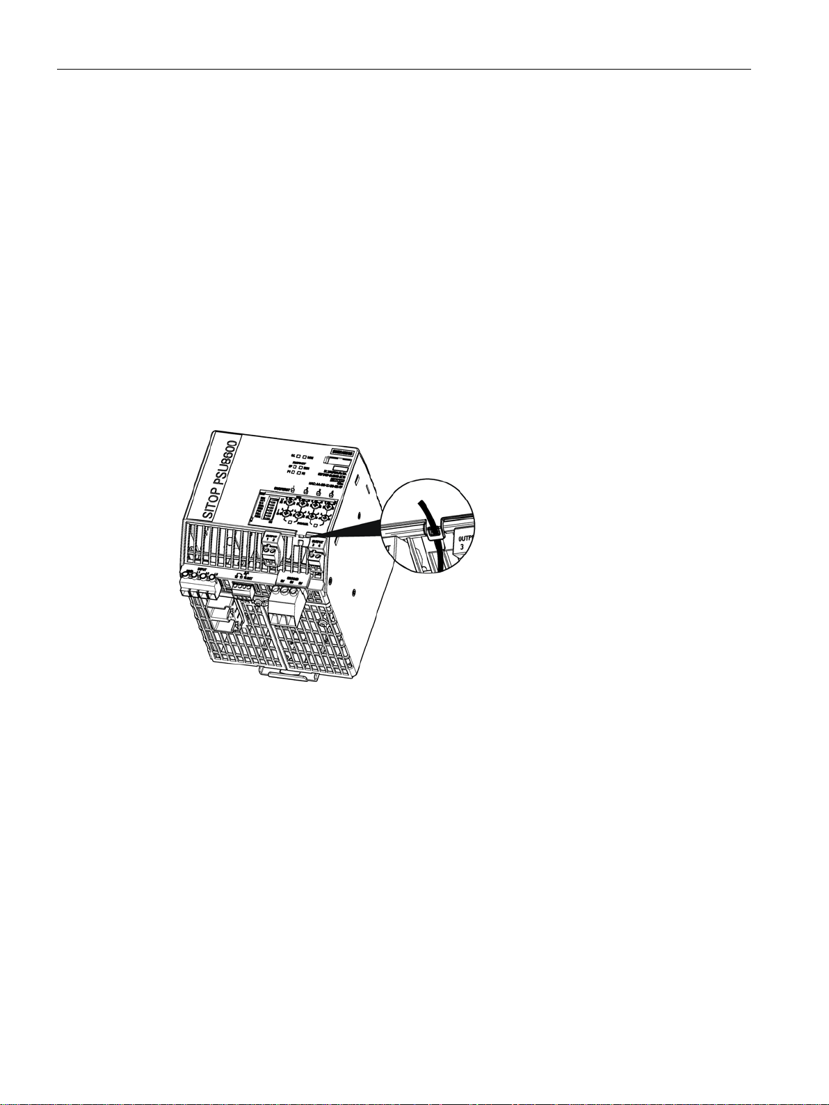
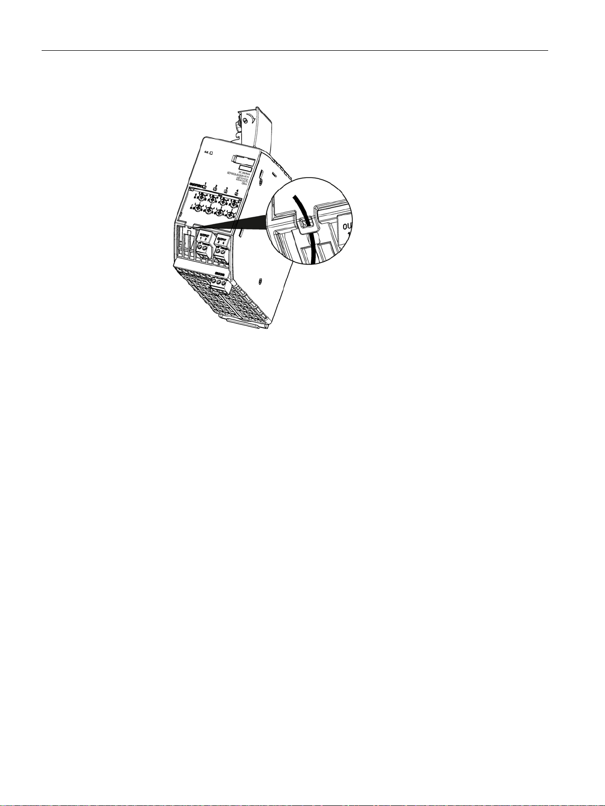
The operating elements, with the exception of the buttons, are protected against
unauthorized operation by a transparent plastic cover. When required, this plastic cover can
be sealed to prevent the operating elements being actuated by unauthorized personnel. For
sealing, the sealing wire can be routed through an opening in the plastic cover and housing,
as shown in the diagram below.
Setting the output voltage (Page 53)
Setting the response threshold value of the output current (Page 54)
Switching-in and switching-out outputs (Page 55)
Overload shutdown and carrying out a reset (Page 56)
MANUAL and REMOTE operating modes (Page 59)
Prioritization when the power fails (Page 62)
ELECTRONIC SHUTDOWN and CONSTANT CURRENT operating modes (Page 64)
Setting the on delay (Page 66)
Connecting outputs of the basic unit in parallel (Page 69)
Activating the web server on the module (Page 72)
PSU8600power supply systems
26 Manual, 04.2016, A5E35883207-7-76
Description, device design, dimension drawing
2.5.2
Expansion modules
No. Designation /
labeling
Function
①
potentiometer "U (V)"
(Page 53).
②
(Page 54).
③
out a reset (Page 56).
Protection and sealing
2.5 Operator controls
The SITOP CNX8600 expansion modules have a main operating area with potentiometers
① and ②) and an LED button ③: The potentiometers are used to set the output voltage
(
and response threshold of the output current. The potentiometers can be individually set for
each output. The individual outputs can be switched-on and switched-off using the buttons;
further, each output can be manually reset after an electronic shutdown.
Voltage
Current
potentiometer "I (A)"
LED buttons
"ON/OFF/RST"
Sets the voltage of the relevant output; see Setting the output voltage
Sets the response threshold of the output current of the relevant output;
see Setting the response threshold value of the output current
Switches in and switches out the various outputs, or resets the particular outputs after an electronic shutdown; see Switching-in and switching-out outputs (Page 55) as well as Overload shutdown and carrying
The operating elements, with the exception of the buttons, are protected against
unauthorized operation by a transparent plastic cover. When required, this plastic cover can
be sealed to prevent the operating elements being actuated by unauthorized personnel. For
sealing, the sealing wire can be routed through an opening in the plastic cover and housing,
as shown in the diagram below.
PSU8600power supply systems
Manual, 04.2016, A5E35883207-7-76
27
Description, device design, dimension drawing
See also
2.5 Operator controls
Setting the output voltage and response threshold value of the output current (Page 53)
Overload shutdown and carrying out a reset (Page 56)
PSU8600power supply systems
28 Manual, 04.2016, A5E35883207-7-76
Description, device design, dimension drawing
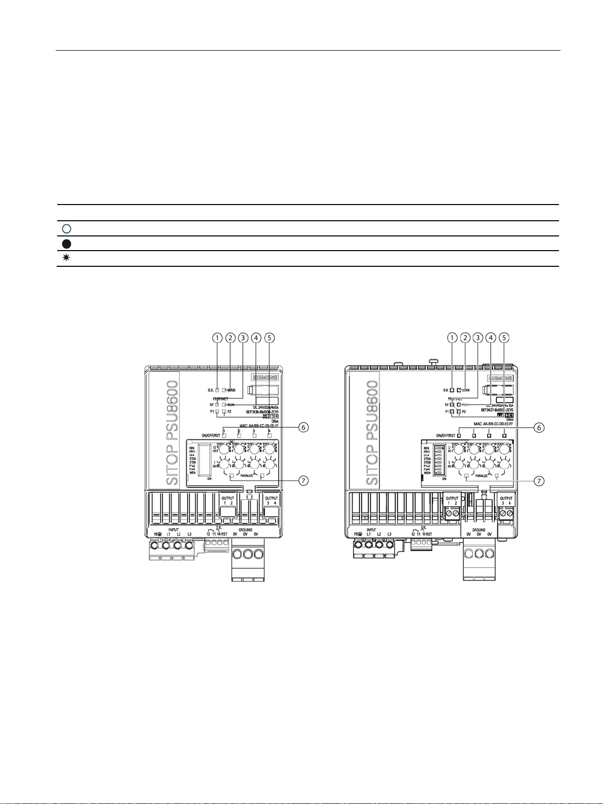
2.6
Displays
Meaning of the LEDs
Signaling
LED is off.
LED is continuously on
x /y
LED flashes in the interval x s on and y s off
2.6.1
Basic devices
No.
Labeling
Signal type
Signaling
①
OK
LED
Device status
②
MAN
LED
Mode
③
SF
LED
Group error
④
RUN
LED
RUN/STOP
⑤
P1/P2
LED
Receive/transmit, port 1 and port 2
⑥
ON/OFF/RST
LED buttons
Operating state of the particular output
⑦
of outputs 1 and 2, outputs 3 and 4
2.6 Displays
The operating state of the device and the operating state of the various outputs are
displayed using multi-color LEDs.
Symbols indicate the significance of each LED, which are listed in the following table.
Parallel LED Parallel connection
PSU8600power supply systems
Manual, 04.2016, A5E35883207-7-76
29

Description, device design, dimension drawing
States of the individual LEDs
Signaling
Off
Device is OFF or is powering up (booting)
Green
Normal operation
operation with rated load for approx. 10 min. is permissible)
200 ms)
Yellow
Power failure, buffer mode active
(operation is permissible for 5 s/min)
(0.25/0.25)
MAN
Signaling
Green
MANUAL mode, i.e. setting directly at the device
the device do not necessarily correspond to the active reference parameters.
2.6 Displays
Table 2- 4 LED "OK" ①
Flashing green (1/1)
Flashing green (0.25/0.25)
Red
Flashing red (0.25/0.25)
Flashing yellow (0.25/0.25)
Alternating, green/red
Table 2- 5 LED "
Phase dissymmetry or phase failure (detected from a total load current > 20 A,
System overload in normal operation:
Summed output power in the range 101 - 150 %
(up to 149%: operation permissible for 5 s, 150 %: operation permissible for
• ERROR OFF: Device has automatically shut down as a result of device over-
temperature, phase dissymmetry, system overload
• Internal device fault
• Device ready for the automatic ERROR OFF shutdown to be reset – or after
a firmware update has been completed, by switching off the supply voltage
and switching it on again (power OFF/ON)
• Incorrect hardware configuration (REMOTE mode)
System overload in buffer mode: Total output power in the range 101 … 150 %
Firmware being updated
" ②
Off
• Device is OFF or is powering up (booting)
• REMOTE mode, i.e. parameterization and remote control via PROFINET or
web server
Flashing green (1/1)
PSU8600power supply systems
MANUAL mode; the mode has been changed in operation, settings directly at
30 Manual, 04.2016, A5E35883207-7-76
 Loading...