

Siemens SITOP, SITOP PSE200U User Manual

___________________
___________________
___________________
___________________
___________________
___________________
___________________
___________________
___________________
___________________
___________________
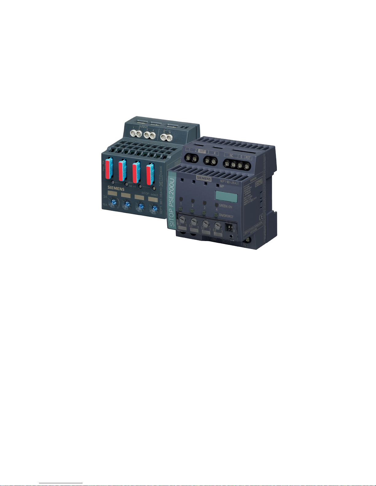
SITOP power supply
Selectivity modules
Manual
SITOP select 4 x 10 A
6EP1961
-2BA00
SITOP PSE200U 4 x 3
A
6EP1961
-2BA11
6EP1961
-2BA31
6EP1961
-2BA51
6EP1961
-2BA61
SITOP PSE200U 4 x 10
A
6EP1961
-2BA21
6EP1961-2BA41
01.2017
C98130
-A7579-A1-2-7629
Overview
Safety notes
1
Description, device design,
dimension drawing
2
Mounting/removal
3
Mounting position, mounting
clearances
4
Installation
5
Technical data
6
Safety, approvals, EMC
7
Environmental conditions
8
Environment
9
Service & Support
10
Siemens AG
Division Process Industries and Drives
Postfach 48 48
90026 NÜRNBERG
GERMANY
C98130-A7579-A1-2-7629
Ⓟ
02/2017 Subject to change
Copyright © Siemens AG 2017.
All rights reserved
Legal information
Warning notice system
This manual contains notices you have to observe in order to ensure your personal safety, as well as to prevent
damage to property. The notices referring to your personal safety are highlighted in the manual by a safety alert
symbol, notices referring only to property damage have no safety alert symbol. These notices shown below are
graded according to the degree of danger.
DANGER
indicates that death or severe personal injury will result if proper precautions are not taken.
WARNING
indicates that death or severe personal injury may result if proper precautions are not taken.
CAUTION
indicates that minor personal injury can result if proper precautions are not taken.
NOTICE
indicates that property damage can result if proper precautions are not taken.
If more than one degree of danger is present, the warning notice representing the highest degree of danger will
be used. A notice warning of injury to persons with a safety alert symbol may also include a warning relating to
property damage.
Qualified Personnel
The product/system described in this documentation may be operated only by
personnel qualified
for the specific
task in accordance with the relevant documentation, in particular its warning notices and safety instructions.
Qualified personnel are those who, based on their training and experience, are capable of identifying risks and
avoiding potential hazards when working with these products/systems.
Proper use of Siemens products
Note the following:
WARNING
Siemens products may only be used for the applications described in the catalog and in the relevant technical
documentation. If products and components from other manufacturers are used, these must be recommended
or approved by Siemens. Proper transport, storage, installation, assembly, commissioning, operation and
maintenance are required to ensure that the products operate safely and without any problems. The permissible
ambient conditions must be complied with. The information in the relevant documentation must be observed.
Trademarks
All names identified by ® are registered trademarks of Siemens AG. The remaining trademarks in this publication
may be trademarks whose use by third parties for their own purposes could violate the rights of the owner.
Disclaimer of Liability
We have reviewed the contents of this publication to ensure consistency with the hardware and software
described. Since variance cannot be precluded entirely, we cannot guarantee full consistency. However, the
information in this publication is reviewed regularly and any necessary corrections are included in subsequent
editions.
Selectivity modules
Manual, 01.2017, C98130-A7579-A1-2-7629
3
Overview
Description
In conjunction with a 24 V power supply, the selectivity module is used to distribute the load
current across several branches and to monitor the individual currents in these branches.
Faults in the individual branches caused by overload or short-circuit are detected and
selectively switched off, so that the fault does not impact the other load circuits. This means
fast troubleshooting and minimized downtimes.
The key benefits of the product include:
● A maximum of 4 load branches are monitored for each module
● The response threshold can be continually set for each output using a potentiometer
● Overcurrents are reliably switched off, independent of the cable length and cable cross-
section
● The 24 V supply for the other loads is maintained
● Multi-colored LED for each output for faster troubleshooting on-site
● Floating group signal contact for remote diagnostics (for -2BA00, -2BA11, -2BA21,
-2BA51)
● Single-channel signal to serially indicate the state of the individual outputs (for -2BA31,
-2BA41, -2BA61)

Overview
Selectivity modules
4 Manual, 01.2017, C98130-A7579-A1-2-7629
● Evaluation using free-of-charge SIMATIC S7 function blocks (S7-300/400/1200/1500) for
modules with single channel signal
● It can be selected that the load branches are sequentially switched on to reduce the total
inrush current
● Versions for limited output power ratings according to NEC Class 2 (maximum, 100 VA).
Ordering data
The following device options are available:
Selectivity modules
Type
Order number
SITOP select
24 V DC input
Number of outputs: 4
Setting range of the response threshold: 2 - 10 A with group signal contact
6EP1961-2BA00
SITOP PSE200U
24 V DC input
Number of outputs: 4
Setting range of the response threshold: 0.5 - 3 A with group signal contact
6EP1961-2BA11
SITOP PSE200U
24 V DC input
Number of outputs: 4
Setting range of the response threshold: 3 - 10 A with group signal contact
6EP1961-2BA21
SITOP PSE200U
24 V DC input
Number of outputs: 4
Setting range of the response threshold: 0.5 - 3 A with single channel signal
6EP1961-2BA31
SITOP PSE200U
24 V DC input
Number of outputs: 4
Setting range of the response threshold: 3 - 10 A with single channel signal
6EP1961-2BA41
SITOP PSE200U
24 V DC input
Number of outputs: 4
Setting range of the response threshold: 0.5 - 3 A with group signal contact NEC Class 2
6EP1961-2BA51
SITOP PSE200U
24 V DC input
Number of outputs: 4
Setting range of the response threshold: 0.5 - 3 A with single channel signal NEC Class 2
6EP1961-2BA61

Overview
Selectivity modules
Manual, 01.2017, C98130-A7579-A1-2-7629
5
Accessories
Type
Order number
Flat insertable fuse: Manufacturer, Littelfuse, series FKS,
19 mm long (for 6EP1961-2BA00)
162.6185.* (FKS-32), 166.7000.* (FKS-80)
Device identification label 20 mm × 7 mm, pastel turquoise
3RT1900-1SB20 (for 6EP1961-2BA11, -2BA21, -2BA31, -
2BA41, -2BA51, -2BA61)
3RT1900-1SB20

Overview
Selectivity modules
6 Manual, 01.2017, C98130-A7579-A1-2-7629

Selectivity modules
Manual, 01.2017, C98130-A7579-A1-2-7629
7
Table of contents
Overview................................................................................................................................................. 3
1 Safety notes ............................................................................................................................................ 9
2 Description, device design, dimension drawing...................................................................................... 11
2.1 Device description ................................................................................................................... 11
2.2 Connections and terminal designation.................................................................................... 12
2.3 Potentiometer .......................................................................................................................... 14
2.4 Status displays and signaling ................................................................................................. 15
2.5 Buttons and selector switches ................................................................................................ 19
2.5.1 SITOP select ........................................................................................................................... 19
2.5.2 SITOP PSE200U .................................................................................................................... 20
2.6 Electronic overload shutdown and reset ................................................................................. 21
2.6.1 SITOP select ........................................................................................................................... 21
2.6.2 SITOP PSE200U .................................................................................................................... 23
2.7 Setting the switch-on delay time ............................................................................................. 26
2.7.1 SITOP select ........................................................................................................................... 26
2.7.2 SITOP PSE200U .................................................................................................................... 28
2.8 Block diagram ......................................................................................................................... 29
2.9 Dimensions and weight ........................................................................................................... 31
3 Mounting/removal ................................................................................................................................. 33
4 Mounting position, mounting clearances ................................................................................................ 35
4.1 Standard mounting position .................................................................................................... 35
4.2 Other mounting positions ........................................................................................................ 37
4.2.1 6EP1961-2BA00 ..................................................................................................................... 37
4.2.2 6EP1961-2BA11, 6EP1961-2BA31, 6EP1961-2BA51 and 6EP1961-2BA61 ........................ 39
4.2.3 6EP1961-2BA21 and 6EP1961-2BA41 .................................................................................. 41
5 Installation ............................................................................................................................................ 43
5.1 Input side connection .............................................................................................................. 43
5.2 Output-side connection ........................................................................................................... 45
6 Technical data ...................................................................................................................................... 47
6.1 Input ........................................................................................................................................ 47
6.2 Output ..................................................................................................................................... 47
6.3 Efficiency ................................................................................................................................. 50
6.4 Protection and monitoring ....................................................................................................... 51
6.5 MTBF ...................................................................................................................................... 51

Table of contents
Selectivity modules
8 Manual, 01.2017, C98130-A7579-A1-2-7629
6.6 Mechanical system ................................................................................................................ 51
6.7 Accessories ............................................................................................................................ 52
6.8 Dimension drawing ................................................................................................................ 53
7 Safety, approvals, EMC ........................................................................................................................ 55
7.1 Safety ..................................................................................................................................... 55
7.2 Approvals ............................................................................................................................... 55
7.3 EMC ....................................................................................................................................... 56
8 Environmental conditions ...................................................................................................................... 57
9 Environment ......................................................................................................................................... 59
10 Service & Support ................................................................................................................................. 61
Selectivity modules
Manual, 01.2017, C98130-A7579-A1-2-7629
9
1
WARNING
Correct handling of the devices
When operating electrical devices, it is inevitable that certain components will carry
dangerous voltages.
Therefore, failure to handle the units properly can result in death or serious physical injury
as well as extensive property damage.
Only appropriately qualified personnel may work on or in the vicinity of this equipment.
Perfect, safe, and reliable operation of this equipment is dependent on proper
transportation, storage, installation and mounting.
Before installation or maintenance work can begin, the system's main switch must be
switched off and measures taken to prevent it being switched on again.
If this instruction is not observed, touching live parts can result in death or serious injury.
WARNING
OPERATE POTENTIOMETERS OR SWITCHES IN NON-HAZARDOUS AREAS ONLY!

Safety notes
Selectivity modules
10 Manual, 01.2017, C98130-A7579-A1-2-7629
Selectivity modules
Manual, 01.2017, C98130-A7579-A1-2-7629
11
2
2.1
Device description
Using the selectivity module, a 24 V DC output voltage from a regulated power supply can
be distributed across four load circuits. The response threshold of the output current can be
individually set for each output using a potentiometer. When the set response threshold is
exceeded, the output is automatically switched off according to a defined switch off
characteristic, and can be switched on again after a wait time using a pushbutton or remote
reset (SITOP PSE200U). The status of the output is displayed using a multi-color LED for
each output. The status of the outputs can be processed via a group signaling contact or via
a serial single-channel signal.
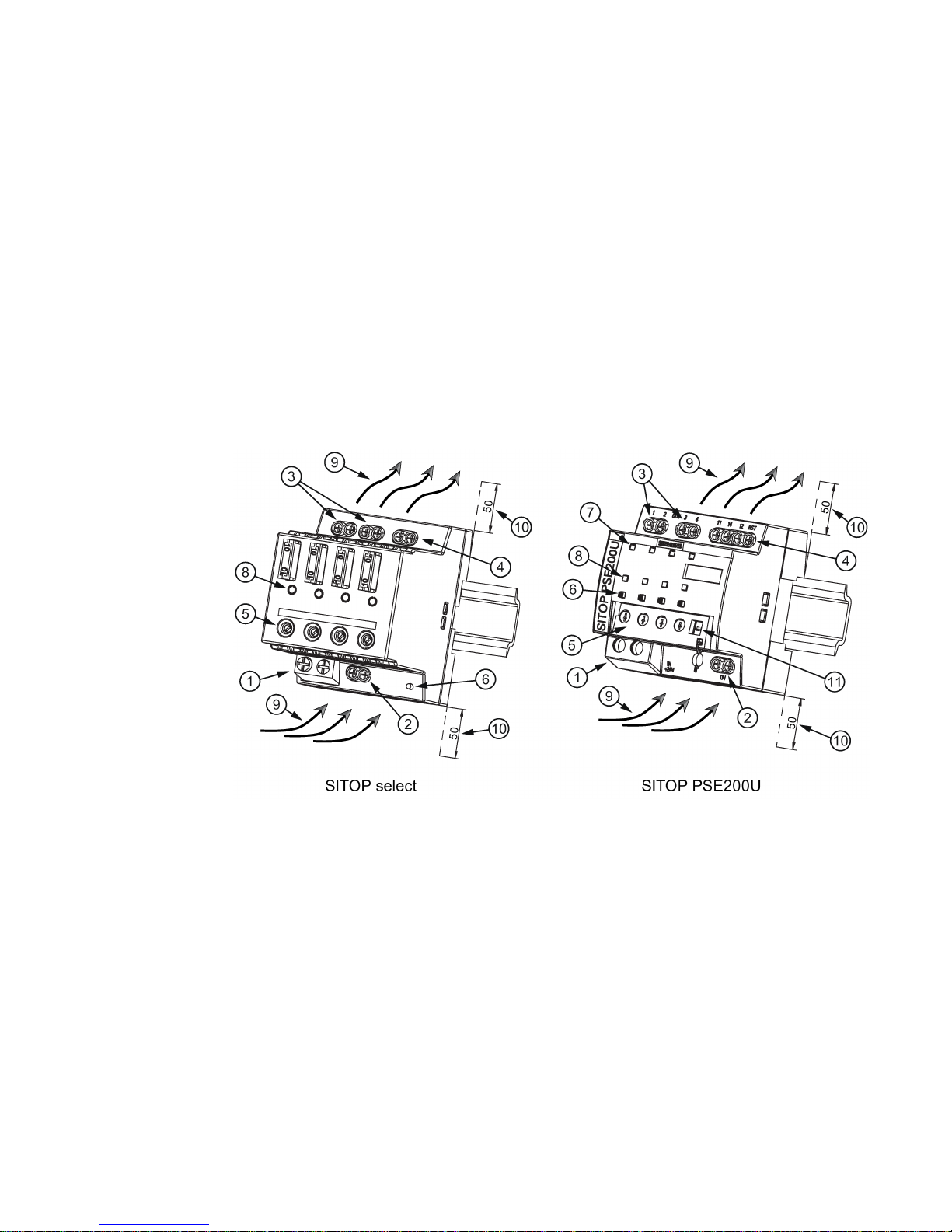
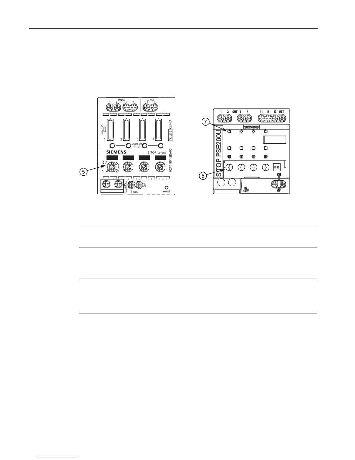
①
+24 V input
②
0 V connection for the internal supply
③
+24 V outputs
④
Group signal contact/status output/remote reset input
⑤
Potentiometer for each output
⑥
Button
⑦
Measuring point
⑧
Indicator light for each output
⑨
Natural convection
⑩
Clearance above/below
⑪
Selector switch for switch-on delay
Figure 2-1 Design

Description, device design, dimension drawing
2.2 Connections and terminal designation
Selectivity modules
12 Manual, 01.2017, C98130-A7579-A1-2-7629
2.2
Connections and terminal designation
The input terminals ① can be used to establish the connection to the supply voltage. The
0 V connection
② is used to supply the internal electronics. Output terminals ③ are used to
connect to the loads to be supplied (also see Chapter Installation (Page 43)).
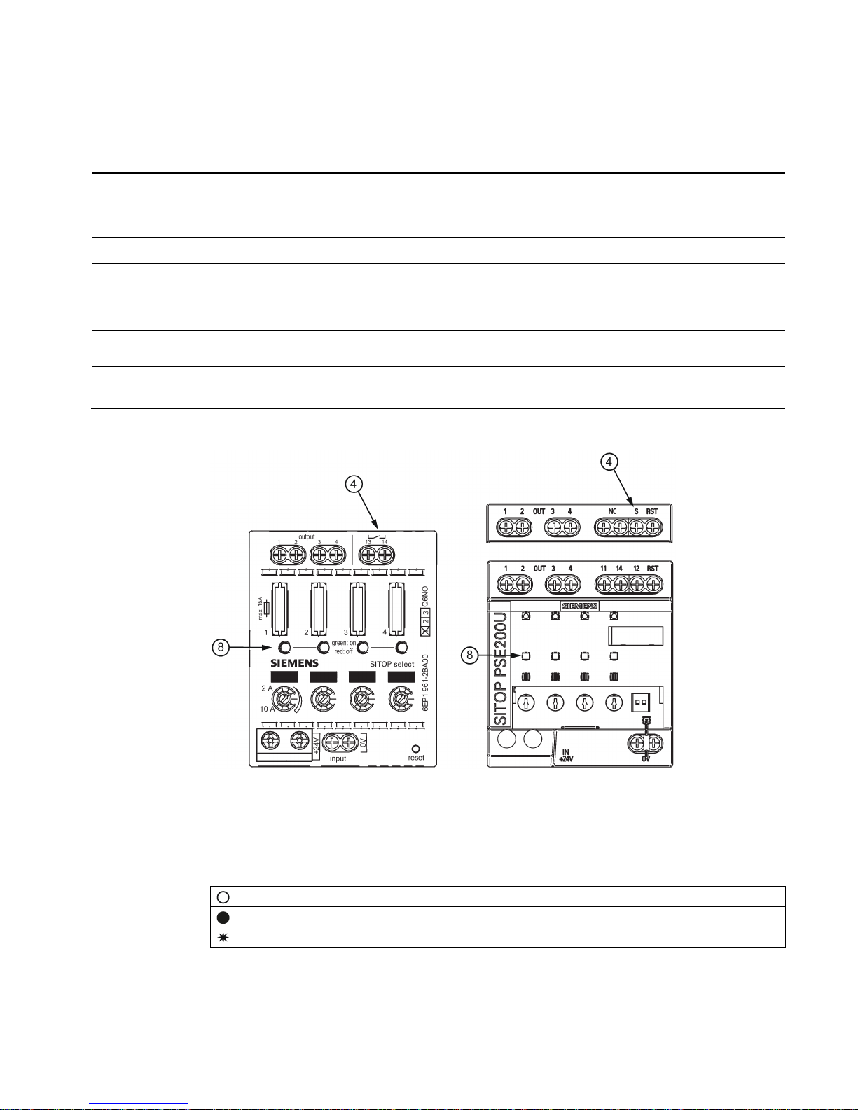
The operating status of the device can be processed using the group signal contact or status
output
④ (function and contact rating, see Figure 2-4 Operating displays and signaling
(SITOP select and SITOP PSE200U) (Page 15)).
The remote reset input
④ is used to reset outputs that have been automatically switched off
(function, see Chapter Status displays and signaling (Page 15)).
Connections and terminal designations for 6EP1961-2BA00
①
+ 24 V input
2 screw terminals
②
0 V connection
2 screw terminals
③
+ 24 V output: 1, 2, 3, 4
One screw terminal each
④
group signal contact (13, 14)
One screw terminal each
Connections and terminal designations for 6EP1961-2BA11, 6EP1961-2BA21 and 6EP1961-2BA51
①
+ 24 V input
2 screw terminals
②
0 V connection
2 screw terminals
③ + 24 V output: 1, 2, 3, 4
One screw terminal each
④ group signal contact (11, 12, 14); remote
reset (RST)
One screw terminal each
Connections and terminal designations for 6EP1961-2BA31, 6EP1961-2BA41 and 6EP1961-2BA61
①
+ 24 V input
2 screw terminals
②
0 V connection
2 screw terminals
③
+ 24 V output: 1, 2, 3, 4
One screw terminal each
④
not assigned (NC)
2 screw terminals
④
status output (S); remote reset (RST)
One screw terminal each
Description, device design, dimension drawing
2.2 Connections and terminal designation
Selectivity modules
Manual, 01.2017, C98130-A7579-A1-2-7629
13
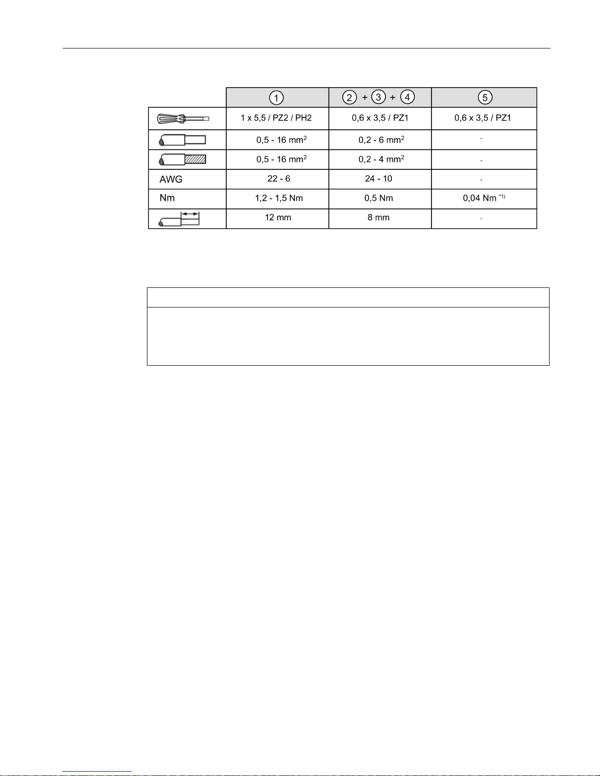
*1)
Do not subject the end stop to higher loads
Figure 2-2 Terminal data
NOTICE
Overload of the wiring
The "0 V" connection is only used to supply the internal electronics of the selectivity
module. The 0 V of the connected loads must be routed directly to the power supply using
separate cables!
Description, device design, dimension drawing
2.3 Potentiometer
Selectivity modules
14 Manual, 01.2017, C98130-A7579-A1-2-7629
2.3
Potentiometer
The potentiometer ⑤ on the front of the device is used to set the response threshold of the
output current. When delivered, the maximum possible response threshold is set.
Figure 2-3 Potentiometer (SITOP select and SITOP PSE200U)
Note
It is only permissible to use an insulated screwdriver when actuating the potentiometer.
For information on actuating the potentiometer (screwdriver, torque), see Figure 2-2
Terminal data (Page 13).
Note
For SITOP PSE200U, the actual output current of a branch can be determined by measuring
the voltage at measuring point "MP"
⑦ with respect to the "0 V" terminal. A measured
voltage of 1
V corresponds to an output current of 1 A.
Description, device design, dimension drawing
2.4 Status displays and signaling
Selectivity modules
Manual, 01.2017, C98130-A7579-A1-2-7629
15
2.4
Status displays and signaling
6EP1961-2BA00
6EP1961-2BA11
6EP1961-2BA21
6EP1961-2BA51
6EP1961-2BA31
6EP1961-2BA41
6EP1961-2BA61
Operating display ⑧
Two-color LED Three-color LED Three-color LED
Group signal contact
(13, 14 or 11, 12, 14) ④
floating relay contact
(NO contact),
contact rating:
24 V/0.5 A
floating relay contact
(changeover contact),
contact rating:
24 V/0.1 A
-
Status output (S) ④
- - Non-floating 24 V DC output,
max. 30 mA
Remote reset input (RST)
④
- Non-floating
24 V DC input
Non-floating
24 V DC input
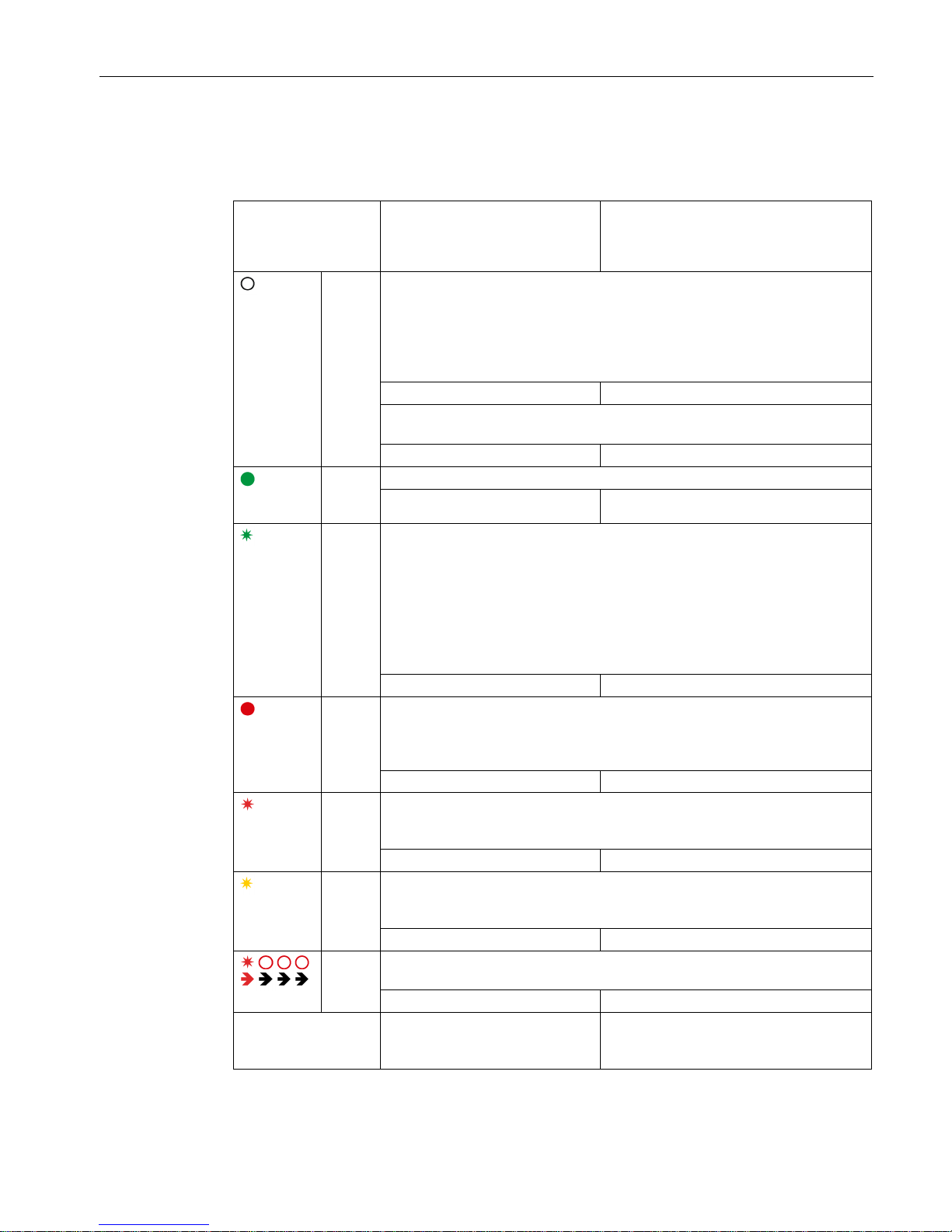
Figure 2-4 Operating displays and signaling (SITOP select and SITOP PSE200U)
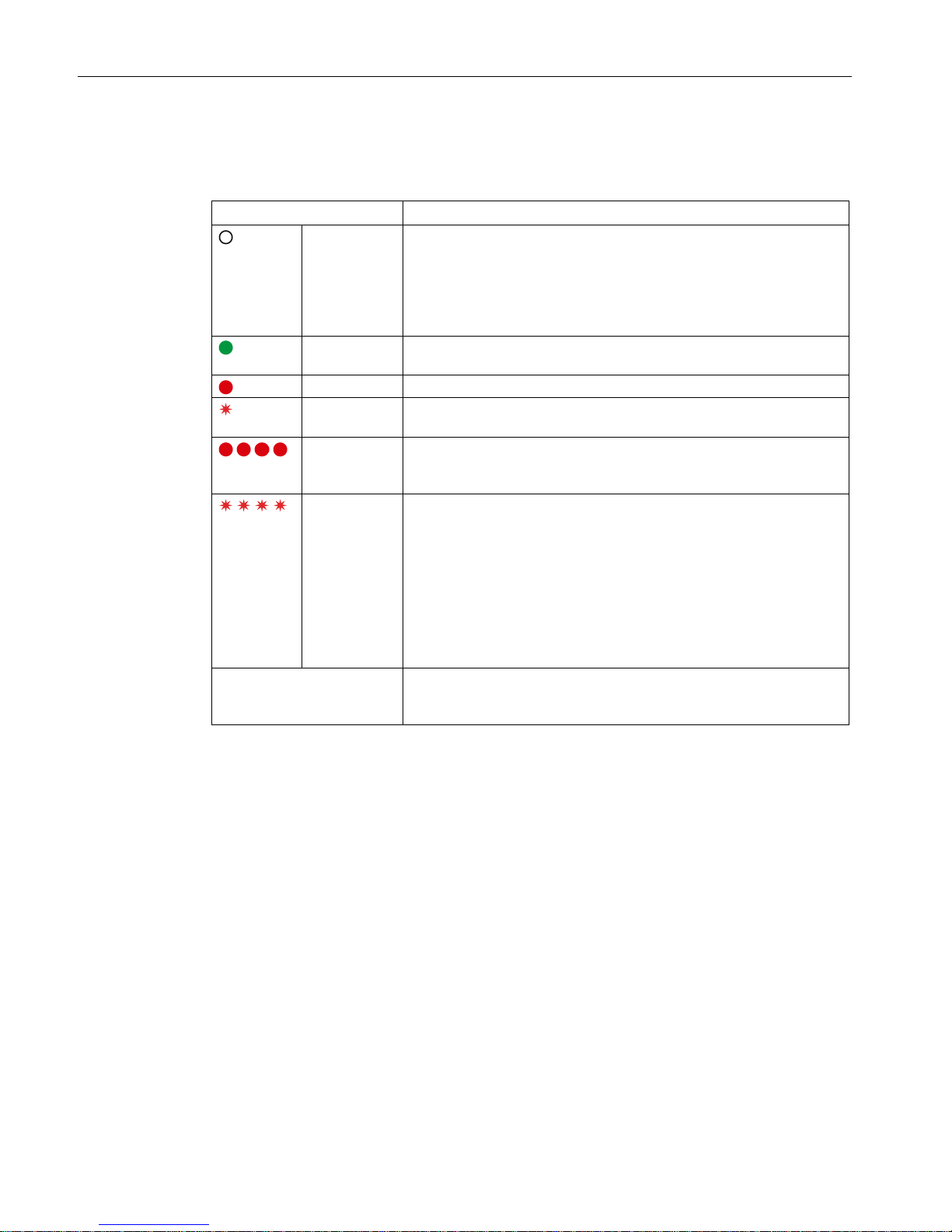
The operating state of the outputs is displayed using multi-color LEDs at the front of the
device. Symbols indicate the significance of each LED, which are listed in the following table.
LED off
LED is continuously lit
LED flashes
Description, device design, dimension drawing
2.4 Status displays and signaling
Selectivity modules
16 Manual, 01.2017, C98130-A7579-A1-2-7629
SITOP select
LED ⑧ and group signaling contact ④
Signaling
6EP1961-2BA00
Off All LEDs:
• No supply voltage
• Device powering up: After the device has powered up, the outputs
are switched on, taking into consideration the switch-on delay that
has been set.
Lights up
green
Normal operation, output is switched on
Lights up red
Output switched off automatically to due overload
Flashes red
Outputs ready to be reset after an automatic switch off by pressing the
button
Light up red
All LEDs are red (after actuating the reset button for a minimum of
8 s):
programming mode for the switch-on delay
Flashes red All LEDs flash red (in the programming mode):
signals the programmed switch-on delay time:
• all LEDs flash 1x simultaneously red, followed by a 2 s pause:
0 ms
• all LEDs flash 2x simultaneously red, followed by a 2 s pause:
24 ms
• all LEDs flash 3x simultaneously red, followed by a 2 s pause:
100 ms
Group signaling contact
(NO contact)
Signal contact (13-14) opens (=quiescent position) when one/several
outputs are switched off as a result of overload or when a fuse rup-
tures.
Description, device design, dimension drawing
2.4 Status displays and signaling
Selectivity modules
Manual, 01.2017, C98130-A7579-A1-2-7629
17
SITOP PSE200U
LED ⑧ and group signaling contact or status output ④
Signaling
6EP1961-2BA11
6EP1961-2BA21
6EP1961-2BA51
6EP1961-2BA31
6EP1961-2BA41
6EP1961-2BA61
Off All LEDs:
• No supply voltage
• Device powering up: After the device has powered up, the outputs are
switched on, taking into consideration the switch-on delay that has been
set.
Group signal: Inactive Status output1*: LED, individual output:
Output defective (internal fuse has ruptured)
Group signal: Inactive Status output1*: Ci = '0'
Lights
up
green
Normal operation, output is switched on
Group signal: Active Status output1*: Ci = '1'
Flashes
green
The output current is in the overload range according to the shutdown characteristic (see Chapter SITOP PSE200U (Page 23))
-2BA11, -2BA21, -2BA31, -2BA41:
overload at the output: Output current 101 - 150 % of the response threshold
(for 5 s)
-2BA51, -2BA61:
overload at the output: Output current 101 - 110 % of the response threshold
(for 5 s)
Group signal: Active
Status output1*: Ci = '1'
Lights
up red
Output automatically shut down due to overload or external overvoltage > typ.
30 V/100 ms. The output can be switched on again after a typical wait time of
20 s. The wait time still to elapse is saved when switching off the device –
and is reactivated after the device has been switched on again.
Group signal: Inactive
Status output1*: Ci = '0'
Flashes red
Output ready to be reset after an automatic switch off by actuating the button
or remote reset (effective for all outputs that have been automatically
switched off)
Group signal: Inactive Status output1*: Ci = '0'
Flashes
orange
Output manually switched off using the button: The state is saved when the
device is switched off, and can only be reset again by pressing the up button
again.
Group signal: Active
Status output1*: Ci = '0'
Red
running
light
Device overtemperature: The outputs can be switched-on again once the
temperature is in the normal range.
Group signal: Inactive
Status output1*: Ci = '0'
Group signaling contact (changeover
contact)
In the "inactive" state, 11-12 are
connected and 11-14 open
-
Description, device design, dimension drawing
2.4 Status displays and signaling
Selectivity modules
18 Manual, 01.2017, C98130-A7579-A1-2-7629
Signaling
6EP1961-2BA11
6EP1961-2BA21
6EP1961-2BA51
6EP1961-2BA31
6EP1961-2BA41
6EP1961-2BA61
Status output - Serial signaling (see Figure 2-5 Status
signaling (Page 18
)), ’1’ = 24 V DC /
’0’ = 0 V (pull down)
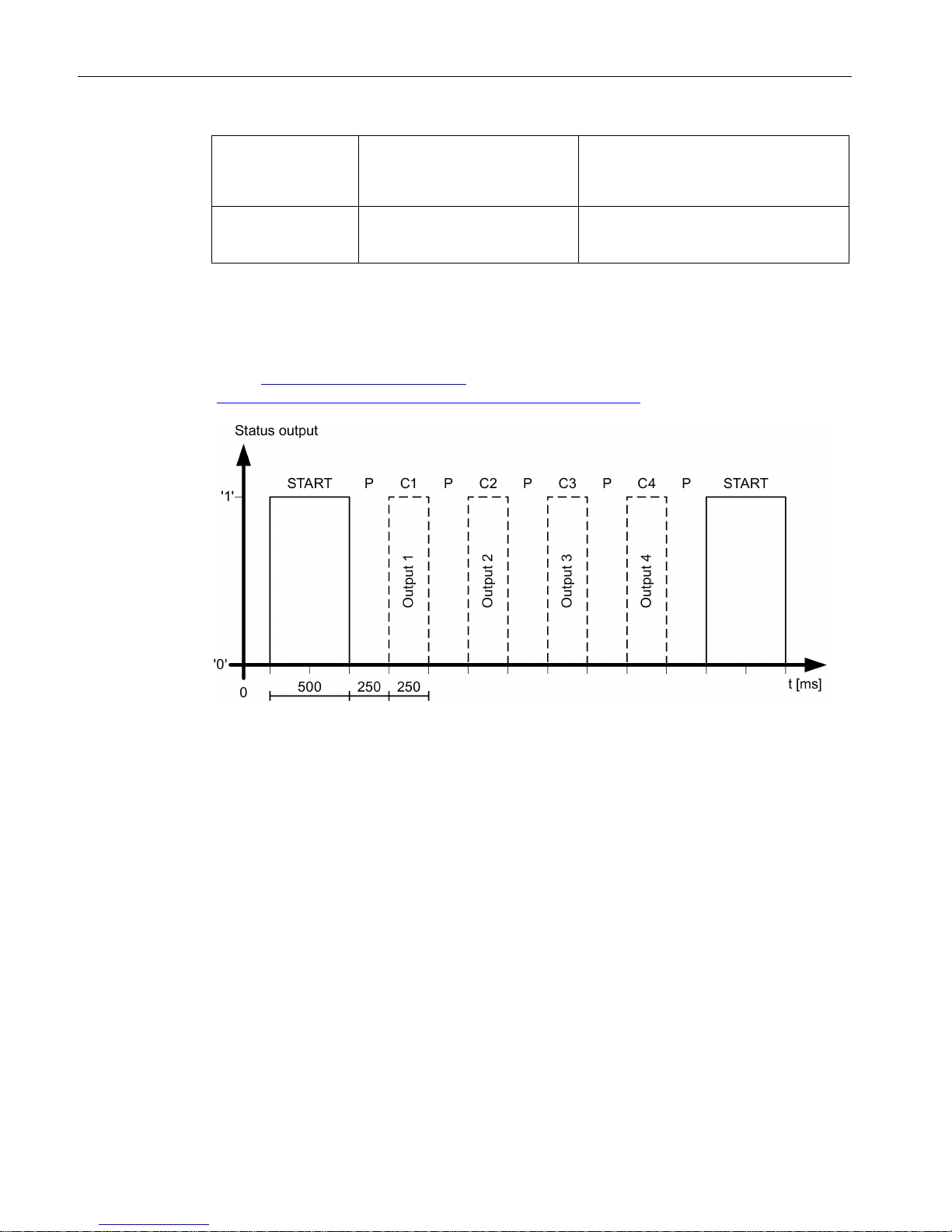
1*
The status of all four outputs is serially signaled using status output ④ (see Figure 2-5
Status signaling (Page 18)). A frame comprises a start bit START and four status bits Ci
(i=1 … 4), which are each separated by a pause bit P. While the device powers up, or if the
supply voltage is missing, nothing is signaled, the status remains continuously at ’0’. For
SIMATIC-S7 controllers (S7-300/400/1200/1500), a function block for evaluation is available
under (http://www.siemens.com/sitop
) or the direct link
(https://support.industry.siemens.com/cs/us/en/view/61450284).
Figure 2-5 Status signaling
Description, device design, dimension drawing
2.5 Buttons and selector switches
Selectivity modules
Manual, 01.2017, C98130-A7579-A1-2-7629
19
2.5
Buttons and selector switches
2.5.1
SITOP select
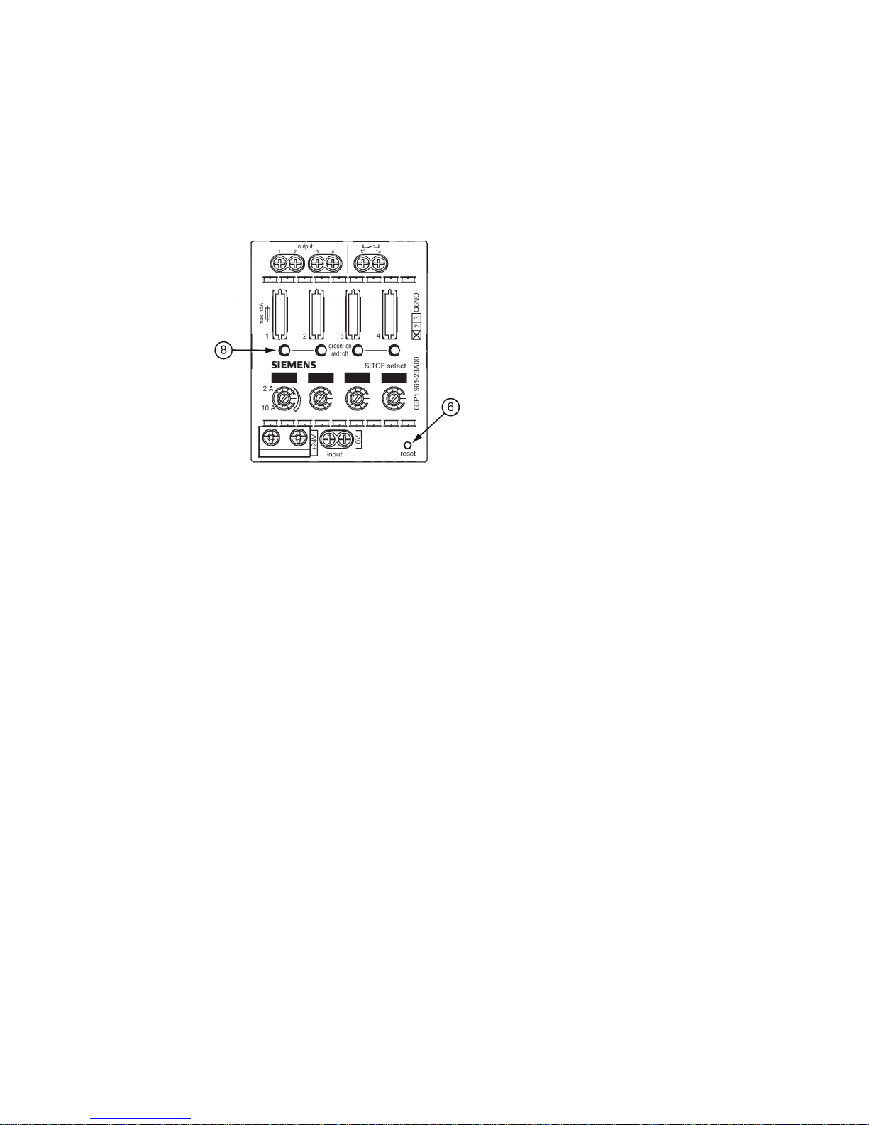
Figure 2-6 Reset button SITOP select
The reset button ⑥ for the SITOP select selectivity module has the following two functions:
1. resets all outputs automatically switched off due to an overload condition (see Chapter
Electronic overload shutdown and reset (Page 21)).
2. is used to program the sequential switch-on delay (see Chapter Setting the switch-on
delay time (Page 26).
 Loading...