

Siemens SISTORE MX, SISTORE MX 3G, SISTORE MX 3G DVD Installation Manual
Building Technologies
Fire Safety & Security Products
SISTORE MX
SISTORE MX DVD
SISTORE MX 3G
SISTORE MX 3G DVD
Hybrid Video Recorder
Installation Manual (EN)
V2.80

Liefermöglichkeiten und technische Änderungen vorbehalten.
Data and design subject to change without notice. / Supply subject to availability.
© 2009 Copyright by
Siemens Building Technologies
Wir behalten uns alle Rechte an diesem Dokument und an dem in ihm dargestellten Gegenstand vor. Der Empfänger erkennt diese Rechte
an und wird dieses Dokument nicht ohne unsere vorgängige schriftliche Ermächtigung ganz oder teilweise Dritten zugänglich machen oder
außerhalb des Zweckes verwenden, zu dem es ihm übergeben worden ist.
We reserve all rights in this document and in the subject thereof. By acceptance of the document the recipient acknowledges these rights
and undertakes not to publish the document nor the subject thereof in full or in part, nor to make them available to any third party without our
prior express written authorization, nor to use it for any purpose other than for which it was delivered to him.
About this document
This document contains instructions for the installation of SISTORE MX and
SISTORE MX 3G units. For information on configuration please refer to the
Configuration Manual. For information on operation please refer to the User
Manual.
Trademarks
SISTORE is a trademark of Fire & Security Products GmbH & Co. oHG.
Microsoft is a registered trademark and Windows a trademark of Microsoft
Corporation.
All other product or company names mentioned in this document are trademarks or
registered trademarks of their respective owners and are used only for purposes of
identification or description.
Contacting us
If you have questions or suggestions regarding the product or this documentation,
please contact our Customer Support Center.
Intranet:
http:/intranet.sbt.siemens.com/fs/CSC
E-Mail:
fs.support.sbt@siemens.com
Tel.: +49 89 9221 8000
Training courses
Siemens Fire & Security Products provides training courses for all products.

3
Siemens Building Technologies
Fire Safety & Security Products 02.2009
EN
Contents
1 Safety .......................................................................................................5
1.1 Target readers...........................................................................................5
1.2 Work safety information ............................................................................5
1.2.1 Transport...................................................................................................5
1.2.2 Installation.................................................................................................5
1.2.3 Service and maintenance .........................................................................6
1.3 Meaning of the written warning notices ....................................................6
1.4 Meaning of the hazard symbols................................................................6
2 EU directives ...........................................................................................7
3 Technical data .........................................................................................8
3.1 SISTORE MX / MX DVD...........................................................................8
3.2 SISTORE MX 3G / MX 3G DVD .............................................................10
4 Details for ordering...............................................................................12
4.1 SISTORE MX / MX DVD.........................................................................12
4.2 SISTORE MX 3G / MX 3G DVD .............................................................14
5 Package contents..................................................................................15
6 Description of SISTORE MX / MX DVD................................................16
6.1 Connections und displays on the front side of the device ......................16
6.2 Connections on the back of the device...................................................17
6.2.1 SISTORE MX 3204.................................................................................17
6.2.2 SISTORE MX 3208 - 3232......................................................................18
6.2.3 Trigger and digital inputs.........................................................................19
6.2.4 Digital outputs .........................................................................................19
6.3 Behaviour with overheating.....................................................................20
7 Description of SISTORE MX 3G / MX 3G DVD....................................21
7.1 Connections und displays on the front side of the device ......................21
7.2 Connections on the back of the device...................................................22
7.2.1 Trigger and digital inputs.........................................................................23
7.2.2 Digital outputs .........................................................................................23
8 Installation .............................................................................................24
8.1 Rack installation......................................................................................24
8.2 Tabletop operation ..................................................................................25
8.3 Setting DIP switches (SISTORE MX / MX DVD) ....................................26
8.4 Examples of system design ....................................................................28
8.4.1 Connecting control panel CKA4810........................................................29
8.4.1.1 SISTORE unit..........................................................................................29
8.4.1.2 SISTORE Remote View..........................................................................30
8.4.2 Connecting control panel CKA4820........................................................31
8.4.2.1 SISTORE unit..........................................................................................31
8.4.2.2 SISTORE Remote View..........................................................................32
8.4.3 Connecting the Multimedia Control Panel (SISTORE MX /
RemoteView)...........................................................................................33
8.4.4 Connecting the Siemens LAN camera CCIx1345...................................40
8.4.5 Connecting the CCDA1425 dome camera .............................................41
8.4.6 Connecting the CCDA1435 dome camera .............................................42
8.4.7 Connecting pan-and-tilt unit PT40 ..........................................................43
8.4.8 Connecting pan-and-tilt unit CDD2410 ...................................................44
8.4.9 Connecting SCU pan-and-tilt unit PT40P via controller CDC050x ......... 44
8.4.10 Connecting SCU pan-and-tilt unit via controller CDCD2417 ..................45

4
Siemens Building Technologies
Fire Safety & Security Products 02.2009
8.4.11 Connecting the MX Multi-Channel Box RCI 0601...................................46
8.4.11.1 Connecting cash dispensers..................................................................46
8.4.11.2 Connecting Kebin access readers .........................................................47
8.4.12 Connecting Miniter interface and access reader.....................................48
8.4.13 Connecting cash box systems ................................................................49
8.4.14 SISTORE unit – CKA4820 – SISTORE RemoteView – LAN cameras...50
9 Software (SISTORE unit) ......................................................................52
9.1 Software operation using the virtual keyboard........................................52
9.2 Updating or repairing software................................................................53
9.3 Subsequent installation of software components....................................54
10 Software (SISTORE RemoteView ........................................................56
10.1 System requirements ..............................................................................56
10.2 Installing SISTORE RemoteView............................................................57
10.3 Updating SISTORE RemoteView ...........................................................59
10.4 Subsequent installation of software components....................................60
11 System limits .........................................................................................60
12 Disposal .................................................................................................60

Safety
5
Siemens Building Technologies
Fire Safety & Security Products 02.2009
EN
1 Safety
1.1 Target readers
The instructions in this document are designed only for the following target
readers:
Target readers Qualification Activity Condition of the
product
Installer Technical training for
electrical installations.
Installs the product,
individual components
of the product or
replacement parts.
Components of the
product are not yet
installed or need to be
replaced or modified.
1.2 Work safety information
z Read the general safety precautions before installing the device.
z Keep this document for later reference.
z Always pass this document on together with the product.
z Please also take into account any additional country-specific, local laws, safety
standards or regulations concerning installation, operation and disposal of the
product.
z Please also read the documentation on the accompanying CD.
Liability claim
z Do not connect the device to the supply network if it is damaged or any parts are
missing.
z Do not make any changes or modifications to the device unless they have
been approved by the manufacturer.
z Use only spare parts and accessories that have been approved by the
manufacturer.
Danger of electrical shock on the open device
z Only qualified personnel should open the unit.
1.2.1 Transport
z Keep the packaging material for future transportation.
z Do not expose the device to mechanical vibrations or shocks.
1.2.2 Installation
Radio interference with other devices in the environment / EMC
z This is a Class A device. This equipment may cause radio interference in a
residential installation. In this case the user is encouraged to perform
appropriate measures to correct the interference.

Safety
6
Siemens Building Technologies
Fire Safety & Security Products 02.2009
Damage due to unsuitable mounting location
z Observe the environmental requirements recommended by the manufacturer.
See Section
3 Technical data.
z Do not operate the device close to sources of powerful electromagnetic
radiation.
z Do not operate the device in dusty places.
z The device should only be used for indoor applications.
z Do not expose the device to mechanical vibrations or shocks.
z Protect the device against moisture.
z Place the unit on a stable surface that will hold its weight.
Damage to the device due to lack of ventilation
z Do not block or cover the ventilation openings of the device. To ensure sufficient
ventilation please also read the instructions in this manual.
z Do not stack several devices on top of each other and do not place any objects
on the device.
Danger of electrical shock/fire hazard/damage to the device due to incorrect
connection
z Connect the device only to power sources with the specified voltage. Voltage
supply requirements can be found on the rating label of the device.
z Use the device only in conjunction with a power supply cable that has been
approved in your country and complies with the national standards.
1.2.3 Service and maintenance
z Do not attempt to service or modify this device yourself. Refer this work to
qualified service personnel.
1.3 Meaning of the written warning notices
The severity of a hazard is indicated by the following written warning notices.
Signal word Type of risk
CAUTION There is a risk of minor to medium injuries or damage to property.
IMPORTANT Malfunctioning may result
1.4 Meaning of the hazard symbols
The nature of the hazard is indicated by icons.
Warning of a hazard
EU directives
7
Siemens Building Technologies
Fire Safety & Security Products 02.2009
EN
2 EU directives
This product complies with the requirements of the following European directives.
The EU declaration of conformity is available to the responsible agencies at:
Siemens Building Technologies
Fire & Security Products GmbH & Co. oHG
76187 Karlsruhe
Germany
European Directive 2004/108/EC „Electromagnetic Compatibility”
Compliance with the European Directive 2004/108/EC has been proven by testing
according to the following standards:
Emitted interference: EN 61000-6-4
EN 55022 Class A
Interference
resistance:
EN 50130-4
European Directive 2006/95/EC „Low-Voltage Directive”
Compliance with the European Directive 2006/95/EC has been proven by testing
according to the following standard:
Safety: EN 60950-1

Technical data
8
Siemens Building Technologies
Fire Safety & Security Products 02.2009
3 Technical data
3.1 SISTORE MX / MX DVD
SISTORE MX 3204
with 4 video inputs
SISTORE MX 3208 - 3232
with 8, 16 or 32 video inputs
Max. 50 fps,
configurable for analogue cameras
Max. 100 fps,
configurable for analogue cameras
Recording speed
Max. 100 fps,
configurable for max. 32 LAN
cameras
Max. 100 fps,
configurable for max. 32 LAN
cameras
Video inputs 4 x CCVS (BNC sockets),
1 Vpp/75 Ohm,
max. 32 LAN camera
8/16/32 x CCVS (BNC sockets),
1 Vpp/75 Ohm,
max. 32 LAN camera
Video outputs 1 x VGA, 2 x CCVS (BNC sockets) 1 x VGA, 4 x CCVS (BNC sockets)
Trigger inputs
16 U
in
B: 5 – 24 V, max. 10 mA 32 UBinB: 5 – 24 V, max. 10 mA
Event control Event-triggered recording of individual cameras or camera groups with
configurable time-slot pattern. Events:
Alarm contact, motion detection, time control, TCP/IP command
Alarm signalling Via monitor connection, digital output, LAN/WAN to RemoteView station,
acoustic signal, e-mail, SMS
Digital inputs 4 for AND operations and system
control functions
U
B
in
B: 5 – 24 V, max. 10 mA
8 for AND operations and system
control functions
UB
in
B: 5 – 24 V, max. 10 mA
Digital outputs 8 switch/key outputs,
configurable switching (rising or
falling edge duration)
U: 5 – 24 V, max. 50 mA
16 switch/key outputs,
configurable switching (rising or
falling edge duration)
U: 5 – 24 V, max. 50 mA
Interfaces 2x RS485, 1 x LAN, 4 x USB 2.0 (0.5 A), 1 x SCSI, 1 x VGA, 1 x Audio in,
1 x Mic in, 1 x Audio out, optionally: S
B
0
B interface for ISDN
Mouse, keyboard Mouse with USB connection, virtual keyboard (optional)
Video standard PAL/NTSC
Analog resolution Standard: 352 x 288 pixels
High resolution: 704 x 288 pixels
Compression M-JPEG, configurable: variable between 10 and 80 KB
Text overlay in the video image Max. 16 characters
Font and background colours Freely selectable
Storage media Basic unit (E)IDE
Memory capacity 250/500/750/1000 GB data memory
External storage media Via network connection
Display resolution 1024 x 768, 1280 x 1024
Playback Individual images, video sequence (replay rate configurable between 0.1 to
50 times), forward/backward, pause (frozen image)
Image search By means of date, time, camera number, recording event, graphic activity
search, logbook, Smartsearch
Video display formats 1x1, 2x2, 1 + 5, 3x3, 2 + 8, 4 + 9, 4x4, 6x6 - 4 (32), 7x7 – 1 (48), 8x8 - (64)
System self-monitoring function Hardware/software watchdog
Power supply 100 – 230 V AC, 50 – 60 Hz, approx. 120 W
Power input Appliance inlet
Temperature range (operation) 5 – 35 °C
Technical data
9
Siemens Building Technologies
Fire Safety & Security Products 02.2009
EN
SISTORE MX 3204
with 4 video inputs
SISTORE MX 3208 - 3232
with 8, 16 or 32 video inputs
Design Embedded
Environmental temperature 5 – 45 °C
Rel. humidity 20 – 80 % without condensation
Dimensions (W x H x D) 430 x 87 x 370 mm
Video compression
Colour resolution Video recording always takes place in YUV 4:2:2 true colour format.
The VGA board must be set to 16-bit mode (Hi-Color). Video compression is
made in JPEG format.
Video input 4/8/16 external composite inputs,
YC signals are not supported.
8/16/24/32 external composite inputs,
YC signals are not supported.
Video output 2 outputs: CVBS,
YC signals are not supported.
4 outputs: CVBS,
YC signals are not supported.
Video standard PAL, NTSC
Video scanning frequency PAL: 13.5 MHz
NTSC: 13.5 MHz
A/D conversion PAL: 1/100 s (20 ms) per field
NTSC: 1/120 s (16.7 ms) per field
Geometric resolution PAL: 704 x 576 pixels with 2 fields
NTSC: 704 x 480 pixels with 2 fields
Optocoupler
Trigger and signal inputs
Number of trigger and signal inputs 16 32
Trigger edge Positive or negative
Triggering of interrupts Yes
Voltage range 5 – 24 V DC
Input current 12 mA (typ.), protected against polarity reversal
Electrical isolation Up to 2500 V
Digital inputs
Number of digital inputs 4 8
Triggering of interrupts No
Voltage range 5 – 24 V DC
Input current 12 mA (typ.), protected against polarity reversal
Electrical isolation Up to 2500 V
Digital outputs
Number of digital outputs 8 16
Output current 50 mA (max.), reversible fuse
Electrical isolation Up to 2500 V
SISTORE MX systems are configured for DHCP by default.
If there is no DHCP server in the network, select the menu sequence Administration>
Configuration, then click the button TCP/IP parameters in the Network tab and enter a permanent
IP address instead of DHCP. Otherwise there may be quite a long waiting time as the system will wait
for a reply from the non-existent DHCP server.

Technical data
10
Siemens Building Technologies
Fire Safety & Security Products 02.2009
3.2 SISTORE MX 3G / MX 3G DVD
SISTORE MX 3G
Max. 400 fps, configurable for 16 analog cameras (max. 25 fps / camera)
Recording speed
Max. 100 fps, configurable for max. 16 LAN cameras
Video inputs 8/16 x CCVS (BNC sockets),
1 Vpp / 75 Ohm, max. 16 LAN cameras
Video outputs 4 x CCVS (BNC sockets)
Alarm inputs 16, UB: 5 V
Event control Event-triggered recording of individual cameras or camera groups with
configurable time-slot pattern.
Events: Alarm contact, motion detection, time control, TCP/IP command,
SMTP, HTTP
Alarm signalling Via monitor connection, digital output, LAN/WAN to RemoteView station,
acoustic signal, e-mail, SMS
Digital inputs 4 for AND operations and system control functions
Digital outputs 4 alarm outputs, configurable switching (rising or falling edge duration)
U: 24 V, max. 50 mA
Interfaces 2x RS485, 2 x LAN, 6 x USB 2.0 (0,5 A), 1 x DVI-I, 1 x DVI-D, 16 x Audio in,
4 x audio out
Mouse, keyboard Mouse with USB connection, virtual keyboard (optional)
Video standard PAL
Analog resolution CIF: 352 x 288 pixels
2CIF: 704 x 288 pixels
4CIF: 704 x 576 pixels
Digital resolution (LAN cameras) Max. 5 megapixels (depending on the camera type)
Compression M-JPEG, configurable: variable between 10 and 160 KB
Text overlay in the video image Max. 16 characters
Font and background colours Freely selectable
Internal storage media Max.: 4 SATA hard disks (1 TB max. each)
Memory capacity SISTORE MX 3G: 1000 – 4000 GB data memory
SISTORE MX 3G DVD: 1000 – 3000 GB data memory
External storage media Via network connection
Display resolution 1024 x 768, 1280 x 1024, 1920 x 1200
Screen format 4:3, 16:10
Playback Individual images, video sequence (replay rate configurable between 0.1 to
50 times), forward/backward, pause (frozen image)
Image search By means of date, time, camera number, recording event, graphic activity
search, logbook, Smartsearch
Video display formats 1x1, 2x2, 1 + 5, 3x3, 2 + 8, 4 + 9, 4x4, 6x6 - 4 (32), 7x7 – 1 (48), 8x8 - (64)
System self-monitoring function Hardware/software watchdog
Power supply 110 – 240 V AC, 50 – 60 Hz, 4 – 2 A
Power input Appliance inlet
Environmental temperature Operation: 5 – 40 °C
Storage: -20 to +70 °C
Rel. humidity 20 – 80 % without condensation
Design Embedded
Dimensions (W x H x D) 430 x 87 x 440 mm
Technical data
11
Siemens Building Technologies
Fire Safety & Security Products 02.2009
EN
SISTORE MX 3G
Video compression
Colour resolution Video recording always takes place in YUV 4:2:2 true colour format.
The VGA board must be set to 16-bit mode (Hi-Color). Video compression is
made in JPEG format.
Video input 16 external composite inputs, YC signals are not supported.
Video output 4 outputs: CVBS, YC signals are not supported.
Video standard PAL
Video scanning frequency PAL 13,5 MHz
A/D conversion PAL 1/100 s (20 ms) per field
Geometric resolution PAL: 704 x 576 pixels with 2 fields
Optocoupler
Trigger and signal inputs
Number of trigger and signal inputs 16
Trigger edge Positive or negative
Triggering of interrupts Yes
Switching voltage 5 V ± 10 %
Switching current Max. 5 mA
Digital inputs
Number of digital inputs 4
Triggering of interrupts No
Digital outputs
Number of digital outputs 4
Output current 50 mA (max.), reversible fuse
Electrical isolation Up to 2500 V
SISTORE MX systems are configured for DHCP by default.
If there is no DHCP server in the network, select the menu sequence Administration>
Configuration, then click the button TCP/IP parameters in the Network tab and enter a permanent
IP address instead of DHCP. Otherwise there may be quite a long waiting time as the system will wait
for a reply from the non-existent DHCP server.

Details for ordering
12
Siemens Building Technologies
Fire Safety & Security Products 02.2009
4 Details for ordering
4.1 SISTORE MX / MX DVD
Further products and accessories can be found in the Internet:
2Hwww.buildingtechnologies.siemens.com > Products & Systems > Electronic
Security > Catalogue Downloads.
Type Part no. Designation Weight*
Without DVD
SISTORE MX 3208 250/200 S24245-F5085-A2 Hybrid recorder, 8 analog cameras,
32 LAN cameras, 250 GB,
100 ips analog, 100 ips digital
approx. 11.0
kg
SISTORE MX 3216 500/200 S24245-F5085-A4 Hybrid recorder, 16 analog cameras,
32 LAN cameras, 500 GB,
100 ips analog, 100 ips digital
approx. 11.0
kg
SISTORE MX 3232 1000/200 S24245-F5085-A6 Hybrid recorder, 32 analog cameras,
32 LAN cameras, 1000 GB,
100 ips analog, 100 ips digital
approx. 11.0
kg
With DVD
SISTORE MX 3204 250/150
DVD
S24245-F5085-A1 Hybrid recorder, 4 analog cameras,
32 LAN cameras, 250 GB,
50 ips analog, 100 ips digital, with DVD
approx. 11.0
kg
SISTORE MX 3208 250/200
DVD
S24245-F5085-A3 Hybrid recorder, 8 analog cameras,
32 LAN cameras, 250 GB,
100 ips analog, 100 ips digital, with DVD
approx. 11.0
kg
SISTORE MX 3216 500/200
DVD
S24245-F5085-A5 Hybrid recorder, 16 analog cameras,
32 LAN cameras, 500 GB,
100 ips analog, 100 ips digital, with DVD
approx. 11.0
kg
SISTORE MX 3232 1000/200
DVD
S24245-F5085-A7 Hybrid recorder, 32 analog cameras,
32 LAN cameras, 1000 GB,
100 ips analog, 100 ips digital, with DVD
approx. 11.0
kg
* Unit incl. packing material, accessories that are included in the delivery, and documentation
All SISTORE MX models have enabled video output and SCSI functions and are
delivered without keyboard.
The part number (PN) of your SISTORE unit will be found on the rating plate on the bottom of the unit.

Details for ordering
13
Siemens Building Technologies
Fire Safety & Security Products 02.2009
EN
Accessories (not included in the delivery)
Type Part no. Designation Weight
Activation of 4 SISTORE MX
video inputs
S24245-P5097-A4 Enables an additional 4 analog video inputs ./.
Activation of 8 SISTORE MX
video inputs
S24245-P5097-A1 Enables an additional 8 analog video inputs ./.
19“ installation kit for
SISTORE MX/CX
C24245-A12-D2 Mounting equipment for installation in a 19“ rack 4.0 kg
MX multichannel box
(GAA/ATM)
S24245-F5092-A1 For connection of cash dispensers,
cash box or access control systems
1.2 kg
SISTORE MX hard drive
expansion kit 250 GByte
2GF4811-8CD For the expansion of SISTORE MX as of V2.50 0.8 kg
SISTORE MX hard drive
expansion kit 500 GByte
S24245-B5093-A1 For the expansion of SISTORE MX as of V2.50 0.8 kg
SISTORE RAID8 2000 S24245-B5108-A1 2 TB RAID system 34.8 kg
SISTORE RAID8 3000 S24245-B5108-A2 3 TB RAID system 38.4 kg
USBOBTO8 2GF4811-8CH USB input module - 8 channels with optocoupler
function
./.
USBREL8 2GF4811-8CG USB output module - 8 channels with relay
function
./.
USBOPTOREL16 2GF4811-8CJ USB input and output modules with 16
optocoupler inputs and 16 relay outputs
./.
USB ISDN module 2GF4811-8FC For use on the SISTORE MX 0.8 kg
SISTORE MX USB mouse A5Q00009353 As a replacement device
SISTORE MX USB keyboard A5Q00009346 For SISTORE MX without keyboard
External USB DVD burner GBQ:S80817 For SISTORE MX without internal DVD burner
CMTC1525 TFT monitor 2GF3124-8AA 15-inch TFT colour monitor for CCTV 6.0 kg
CMTC1725 TFT monitor 2GF3125-8AA 17-inch TFT colour monitor for CCTV 6.5 kg
CMTC1925 TFT monitor 2GF3126-8AA 19-inch TFT colour monitor for CCTV 7.0 kg
Interface converter
RS232C/RS485
2GF5505-8AH Interface converter RS232C/RS485 0.1 kg
Converter model 4855DSR ./. From roline (please order directly from the
manufacturer)
./.
Converter model USB/RS232 ./. From roline (please order directly from the
manufacturer)
./.
KeBin access reader ./. From KEBA (please order directly from the
manufacturer)
./.
Miniter access reader ./. From STM GmbH (please order directly from the
manufacturer)
./.
Multimedia Control Panel
(ShuttlePRO2)
./. From Contour Design Ltd. (please order directly
from the manufacturer)
./.
Details for ordering
14
Siemens Building Technologies
Fire Safety & Security Products 02.2009
4.2 SISTORE MX 3G / MX 3G DVD
Further products and accessories can be found in the Internet:
3Hwww.buildingtechnologies.siemens.com > Products & Systems > Electronic
Security > Catalogue Downloads.
Type Part no. Designation Weight*
Without DVD
SISTORE MX1608 S54569-C201-A3 SISTORE MX1608 HVR, 1000 GB, 300 fps approx.
11.7 kg
SISTORE MX1616 S54569-C202-A3 SISTORE MX1616 HVR, 1000 GB, 500 fps approx.
11.7 kg
With DVD
SISTORE MX1608 DVD S54569-C201-B3 SISTORE MX1608 HVR, DVD, 1000 GB, 300 fps approx.
11.7 kg
SISTORE MX1616 DVD S54569-C202-B3 SISTORE MX1616 HVR, DVD, 1000 GB, 500 fps approx.
11.7 kg
* Unit incl. packing material, accessories that are included in the delivery, and documentation
All SISTORE MX models have enabled video output functions and are delivered
without keyboard.
The part number (PN) of your SISTORE unit will be found on the rating plate on the bottom of the unit.
Accessories (not included in the delivery)
Type Part no. Designation Weight
19“ installation kit for
SISTORE
MX/CX
C24245-A12-D2 Mounting equipment for installation in a 19“ rack 4.0 kg
MX multichannel box
(GAA/ATM)
S24245-F5092-A1 For connection of cash dispensers,
cash box or access control systems
1.2 kg
USBOBTO8 2GF4811-8CH USB input module - 8 channels with optocoupler
function
./.
USBREL8 2GF4811-8CG USB output module - 8 channels with relay
function
./.
USBOPTOREL16 2GF4811-8CJ USB input and output modules with 16
optocoupler inputs and 16 relay outputs
./.
USB ISDN module 2GF4811-8FC For use on the SISTORE MX 0.8 kg
SISTORE MX USB mouse A5Q00009353 As a replacement device
SISTORE MX USB keyboard A5Q00009346 For SISTORE MX without keyboard
External USB DVD burner GBQ:S80817 For SISTORE MX without internal DVD burner
CMTC1525 TFT monitor 2GF3124-8AA 15-inch TFT colour monitor for CCTV 6.0 kg
CMTC1725 TFT monitor 2GF3125-8AA 17-inch TFT colour monitor for CCTV 6.5 kg
CMTC1925 TFT monitor 2GF3126-8AA 19-inch TFT colour monitor for CCTV 7.0 kg

Package contents
15
Siemens Building Technologies
Fire Safety & Security Products 02.2009
EN
Type Part no. Designation Weight
Interface converter
RS232C/RS485
2GF5505-8AH Interface converter RS232C/RS485 0.1 kg
Converter model 4855DSR ./. From roline (please order directly from the
manufacturer)
./.
Converter model USB/RS232 ./. From roline (please order directly from the
manufacturer)
./.
KeBin access reader ./. From KEBA (please order directly from the
manufacturer)
./.
Miniter access reader ./. From STM GmbH (please order directly from the
manufacturer)
./.
Multimedia Control Panel
(ShuttlePRO2)
./. From Contour Design Ltd. (please order directly
from the manufacturer)
./.
5 Package contents
SISTORE MX / MX DVD
z SISTORE unit
z Mouse
z Mains cable
z 8 x digital I/O connector (SISTORE MX 3204)
z 14 x digital I/O connector (SISTORE MX 3208 - 3232)
z Activation form
z CD with the SISTORE MX application software and complete documentation
z Installation Manual
SISTORE MX 3G / MX 3G DVD
z SISTORE unit
z Mouse
z Mains cable
z 2 x 8-pin digital I/O connector
z 2 x 4-pin digital I/O connector
z CD with the SISTORE MX application software and complete documentation
z Installation Manual
Description of SISTORE MX / MX DVD
16
Siemens Building Technologies
Fire Safety & Security Products 02.2009
6 Description of SISTORE MX / MX DVD
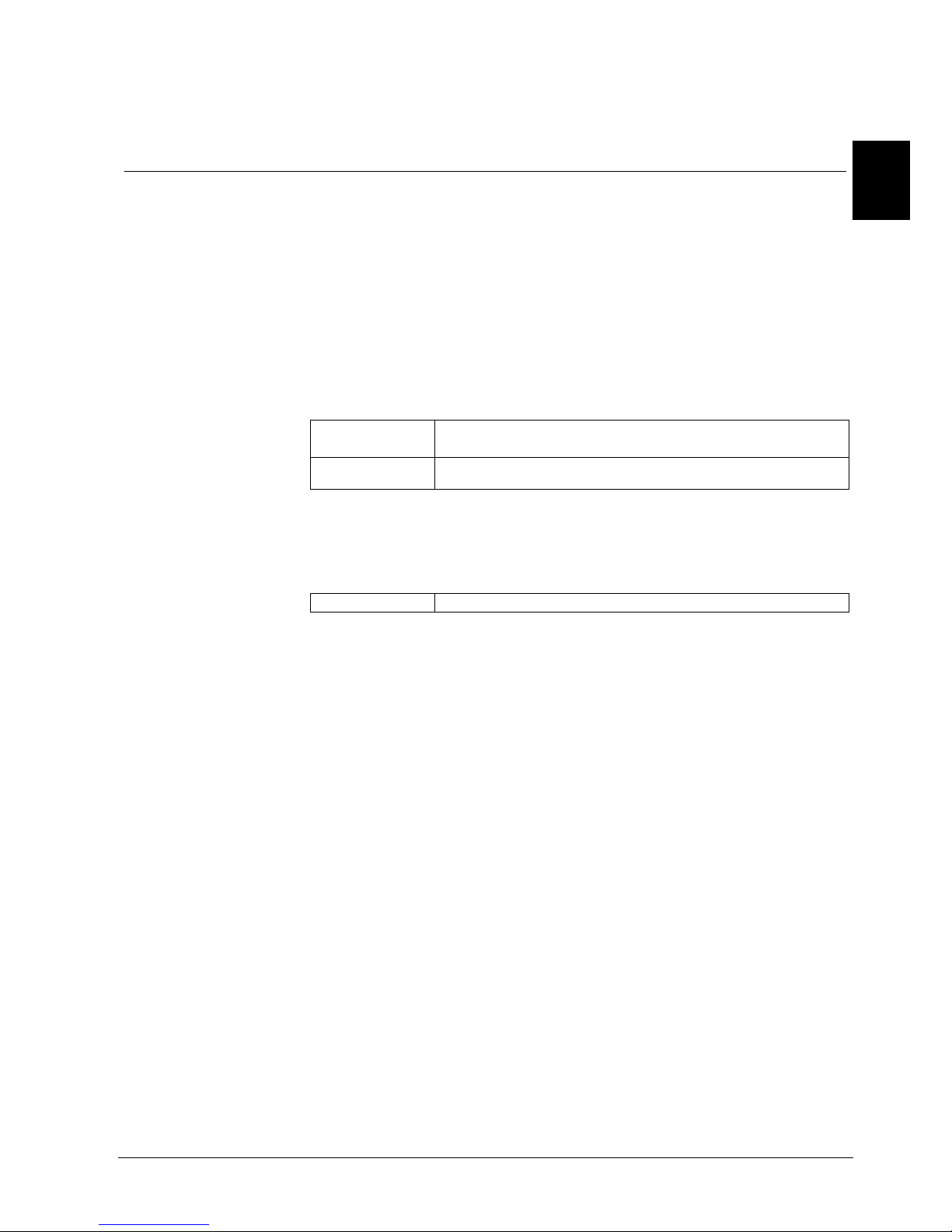
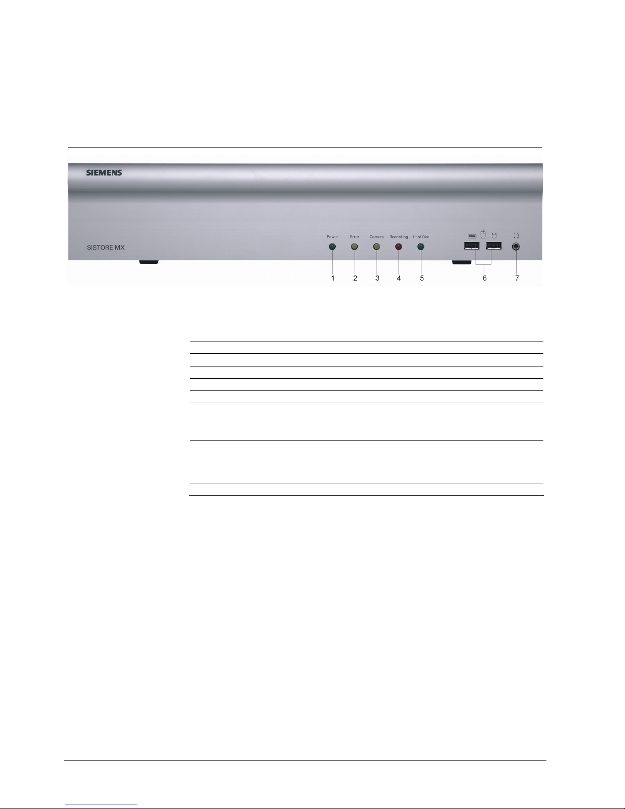
6.1 Connections und displays on the front side of the device
Fig. 1 Front side of SISTORE MX 3204 and SISTORE MX 3208 - 3232
LED displays on the front side of the device
1 Power Lit green: Power supply, unit in operation
2 Error Lit yellow: Error: Alarm, initializing, overheated
3 Camera Lit yellow: Loss of video
4 Recording Lit red: Recording
5 Hard disk Blinking green: Access to internal hard drive(s)
Connections on the front side of the device
6 USB Connection of 2 USB-enabled devices
(e.g. keyboard, mouse, backup hard drive, DVD burner)
Please note: The operation of external USB hard drives as a
memory expansion is not allowed for technical reasons.
7 Headphones Connection of headphones (without amplifier)
Description of SISTORE MX / MX DVD
17
Siemens Building Technologies
Fire Safety & Security Products 02.2009
EN
6.2 Connections on the back of the device
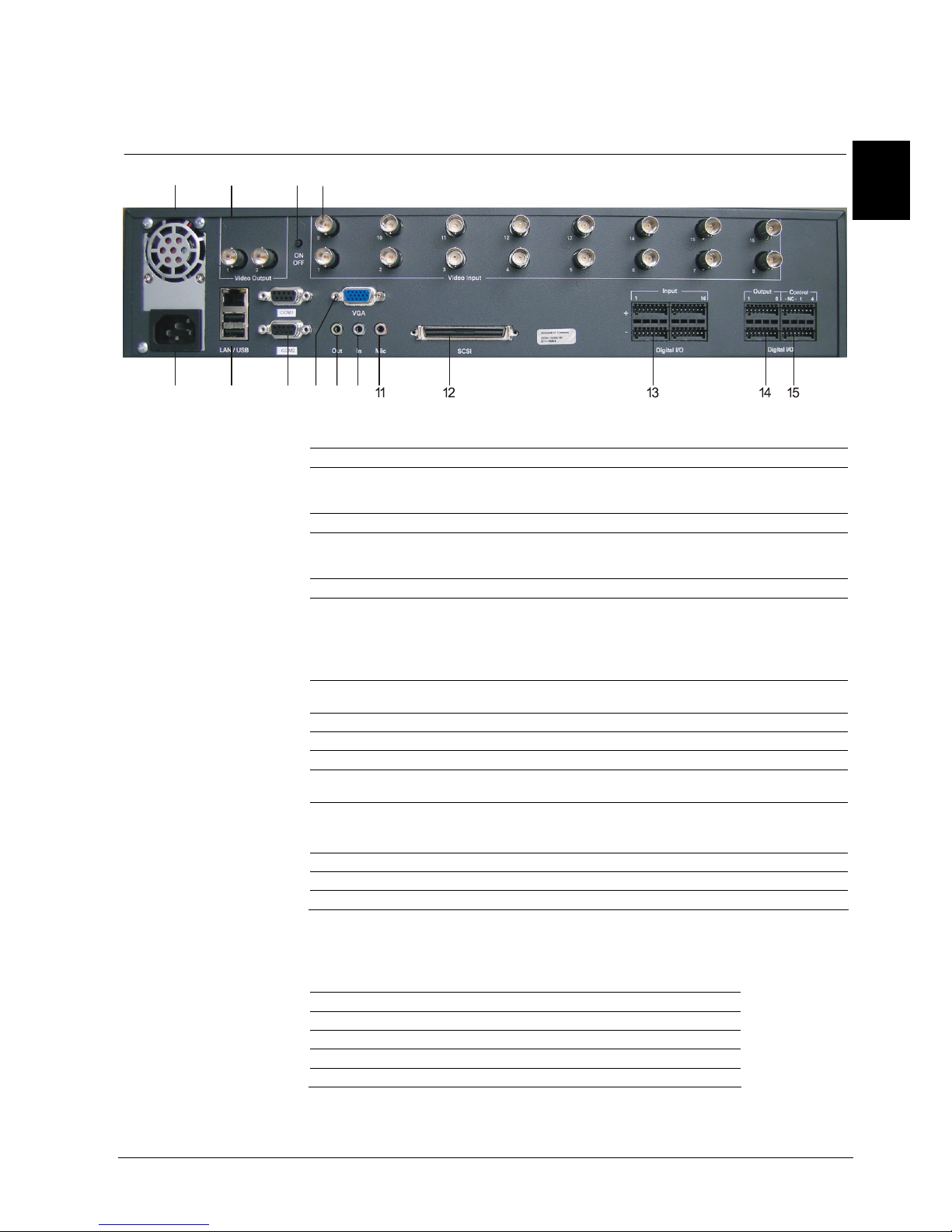
6.2.1 SISTORE MX 3204
1
2
34
5678
910
Fig. 2 Back side of SISTORE MX 3204
1 Fan
2 Video output 2 video outputs, 50 Hz/60 Hz
Connect the same type of unit here as that on the video inputs (PAL, for
example), since otherwise it is not possible to operate the video outputs.
3 ON / OFF Switching the unit on and off
4 Video input 16 video connection jacks
Depending on the model and licence file, up to 32 cameras can be
connected.
5 Power supply 100 – 230 V AC, 50 – 60 Hz, 120 W (use only the power supply provided)
6 LAN/USB LAN: connection of a LAN cable (RJ45 network cable)
USB: Connection of 2 USB-enabled devices
(e.g. USB-ISDN modem, printer, mouse, keyboard, DVD burner)
Please note: The operation of external USB hard drives as a memory
expansion is not allowed for technical reasons.
7 COM 1/COM 2
RS485
Connection for control of pan/tilt cameras, CKA48xx control panel or MX
multichannel box
8 VGA For connecting a monitor, e.g. CTMC 15/17/19
9 L-out Connection of commercially available speakers or headphones
10 L-in Connection of audio sources
11 MIC Connection of a microphone for voice recording
(such as a standard microphone sold as a commercial PC accessory)
12 SCSI For connection of SCSI RAID system, e.g. SISTORE RAID
Connection: HD68
Standard: Ultra Wide SCSI, Single End Mode
13 Digital I/O input Trigger inputs 1 … 16
14 Digital I/O output Digital outputs 1 … 8
15 Digital I/O control Digital inputs 1 ... 4
Pin assignment
RS-485 socket RS-485 socket
PIN 1: NC PIN 6: NC
PIN 2: A (TX+/RX+) PIN 7: NC
PIN 3: B (TX-/RX-) PIN 8: NC
PIN 4: NC PIN 9: NC
PIN 5: GND
Description of SISTORE MX / MX DVD
18
Siemens Building Technologies
Fire Safety & Security Products 02.2009
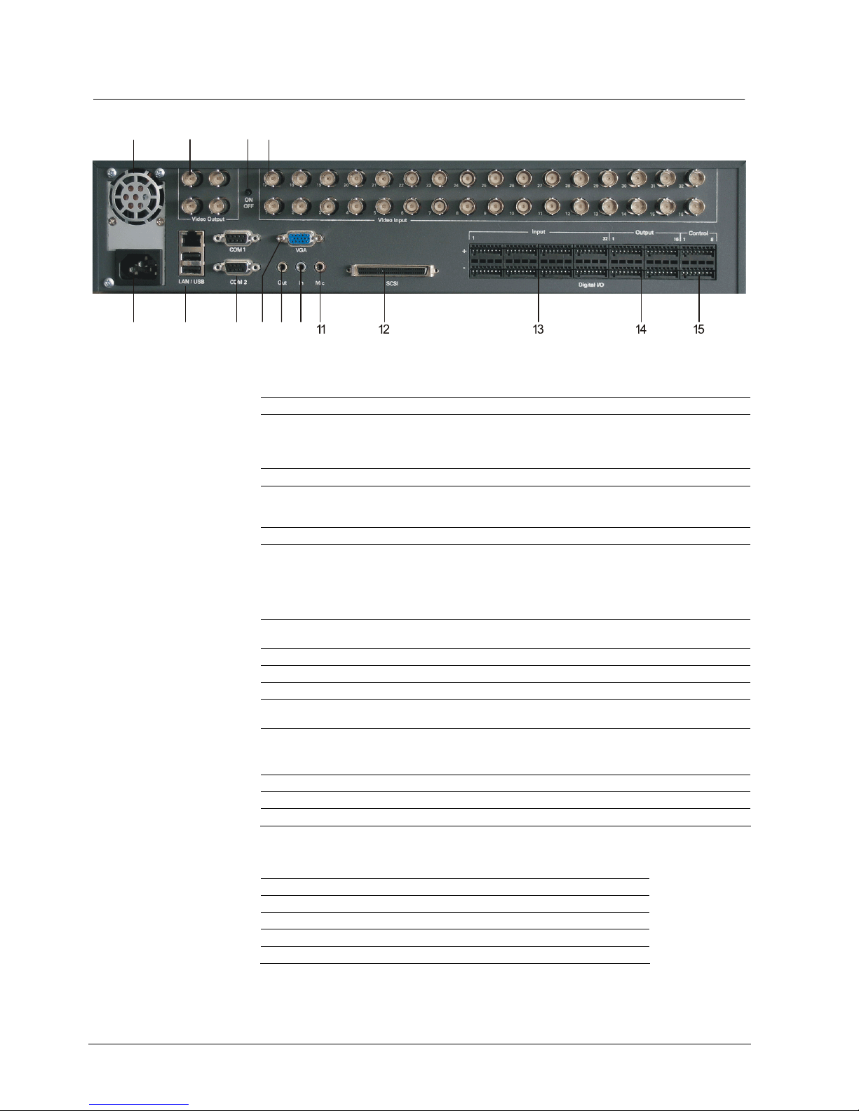
6.2.2 SISTORE MX 3208 - 3232
4
5678
910
321
Fig. 3 Back side of SISTORE MX 3208 - 3232
1 Fan
2 Video output 4 video outputs, 50 Hz/60 Hz
Connect the same type of unit here as that on the video inputs (PAL, for
example), since otherwise it is not possible to operate the video
outputs.
3 ON / OFF Switching the unit on and off
4 Video input 32 video connection jacks
Depending on the model and licence file, up to
32 cameras can be connected.
5 Power supply 100 – 230 V AC, 50 – 60 Hz, 120 W
6 LAN/USB LAN: connection of a LAN cable (RJ45 network cable)
USB: Connection of 2 USB-enabled devices
(e.g. USB-ISDN modem, printer, mouse, keyboard, DVD burner)
Please note: The operation of external USB hard drives as a memory
expansion is not allowed for technical reasons.
7 COM 1/COM 2
RS485
Connection for control of pan/tilt cameras, CKA48xx control panel or
MX multichannel box
8 VGA For connecting a monitor, e.g. CTMC 15/17/19
9 L-out Connection of commercially available speakers or headphones
10 L-in Connection of audio sources
11 MIC Connection of a microphone for voice recording
(such as a standard microphone sold as a commercial PC accessory)
12 SCSI For connection of SCSI RAID system, e.g. SISTORE RAID
Connection: HD68
Standard: Ultra Wide SCSI, Single End Mode
13 Digital I/O input Trigger inputs 1 … 32
14 Digital I/O output Digital outputs 1 … 16
15 Digital I/O control Digital inputs 1 ... 8
RS-485 socket RS-485 socket
PIN 1: NC PIN 6: NC
PIN 2: A (TX+/RX+) PIN 7: NC
PIN 3: B (TX-/RX-) PIN 8: NC
PIN 4: NC PIN 9: NC
PIN 5: GND
Description of SISTORE MX / MX DVD
19
Siemens Building Technologies
Fire Safety & Security Products 02.2009
EN
6.2.3 Trigger and digital inputs
The HVR is equipped with optocoupler that run the TTL-compatible trigger inputs of
the SISTORE MX via optocoupler and enable the switching of signal levels up to
24 V.
The inputs of the optocoupler are designed for a voltage range of 5 to 24 V.
With the SISTORE MX there are 32 trigger inputs and 8 digital inputs available.
These trigger inputs are edge triggered. The trigger edge which is to initiate a
trigger event can be selected with the software (SISTORE RemoteView and
SISTORE MX).
Input circuitry of the optocoupler
Optokoppler
U1
1K2
R
V
5 - 24 V
Digital In
Fig. 4 Optocoupler – input circuitry (example of pin assignment)
The 8 digital inputs can be used to control external events.
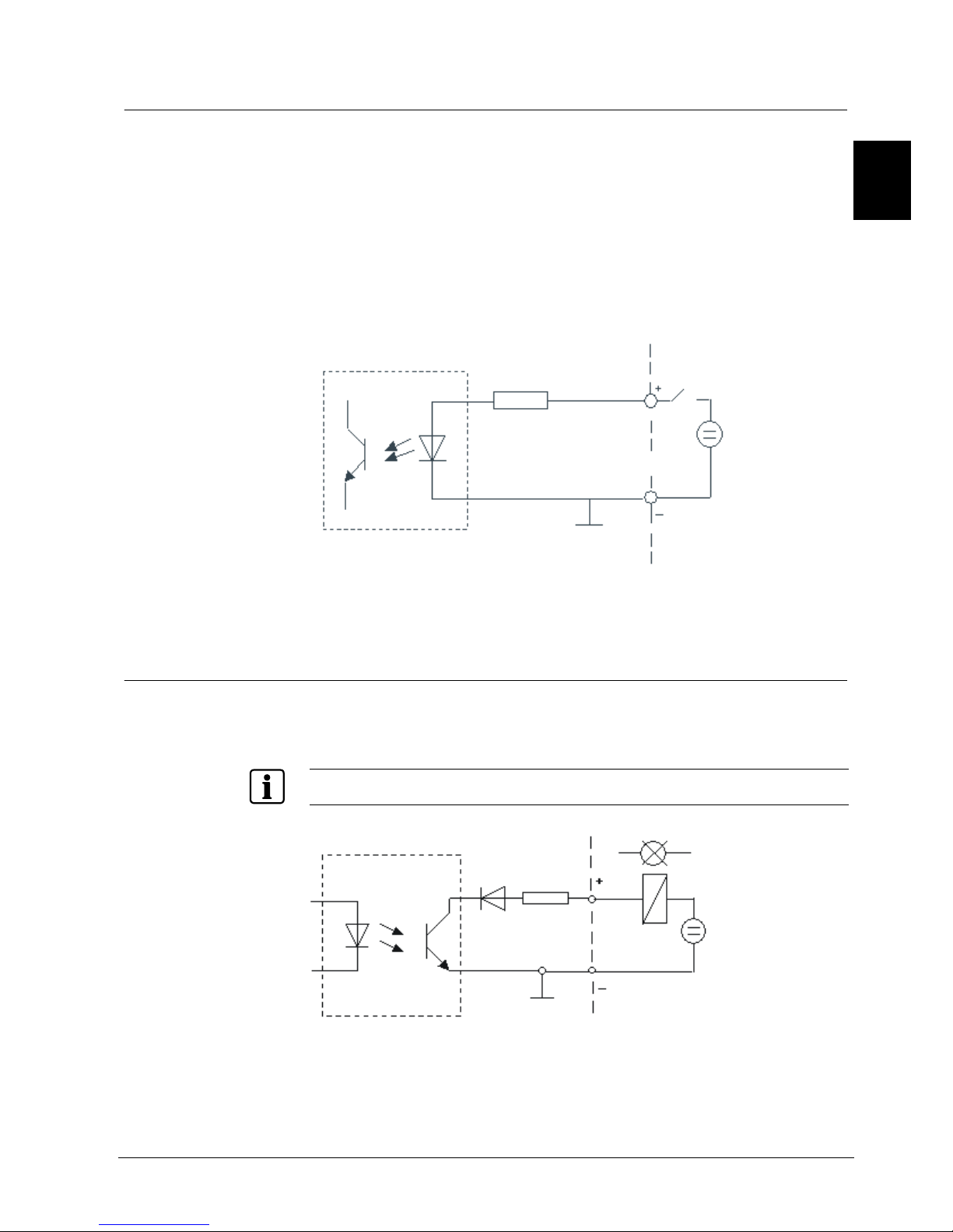
6.2.4 Digital outputs
The outputs ground a connected consumer. All outputs can handle a maximum
current of 50 mA. Fusing of the outputs is implemented with reversible fuses. All
outputs are short circuit proof.
If inductive consumers are connected, we recommend using appropriate protective circuits.
U1
Optokoppler
D1
F1
50 mA
Digital Out
5 - 24 V
Fig. 5 Optocoupler – output circuitry (example of pin assignment)
 Loading...