

Siemens SISTORE MX 3232 1000/200, SISTORE MX 3208 250/200, SISTORE MX 3216 500/200, SISTORE MX 3204 250/150 DVD, SISTORE MX 3208 250/200 DVD User Manual
...
Building Technologies
Fire Safety & Security Products
SISTORE MX
Hybrid Video Recorder
User Manual
Version 2.70 and higher

Liefermöglichkeiten und technische Änderungen vorbehalten.
Data and design subject to change without notice. / Supply subject to availability.
© 2008 Copyright by
Siemens Building Technologies AG
Wir behalten uns alle Rechte an diesem Dokument und an dem in ihm dargestellten Gegenstand vor. Der Empfänger anerkennt diese
Rechte und wird dieses Dokument nicht ohne unsere vorgängige schriftliche Ermächtigung ganz oder teilweise Dritten zugänglich machen
oder außerhalb des Zweckes verwenden, zu dem es ihm übergeben worden ist.
We reserve all rights in this document and in the subject thereof. By acceptance of the document the recipient acknowledges these rights
and undertakes not to publish the document nor the subject thereof in full or in part, nor to make them available to any third party without our
prior express written authorization, nor to use it for any purpose other than for which it was delivered to him.
About this document
This document contains instructions for the operation and configuration of
SISTORE MX, SISTORE MX RemoteView and SISTORE Player. The
SISTORE MX unit is operated using the SISTORE MX application software.
Instructions for installation and setup and technical specifications can be found in
the SISTORE MX Installation Manual.
A complete version of this manual can be found in Adobe Acrobat format (PDF) on
the SISTORE MX CD. This is the most recent version. All subsequent alterations
have been included as far as possible.
Trademarks
SISTORE is a trademark of Siemens Fire & Security Products GmbH & Co. oHG.
IBM PC is a registered trademark of International Business Machines Corporation.
Microsoft is a registered trademark and Windows a trademark of Microsoft
Corporation. All other products or company names referred to explicitly in this
manual are mentioned only for purposes of identification or description and may be
trademarks or registered trademarks of their respective owners.
Copyright
Copyright 2007 © Siemens Fire & Security Products GmbH & Co. oHG.
All rights reserved.
Siemens Fire & Security Products GmbH & Co. oHG confers upon the purchaser
the right to use the software.
It is not permitted to reproduce this manual in whole or in part or translate it into
another language without our written consent.
Contacting us
If you have questions or suggestions regarding the product or this documentation,
please contact your local SIEMENS representative. You can also visit our website
at
http://www.sbt.siemens.com/FSP

3
Siemens Building Technologies
Fire Safety & Security Products 01.2008
Contents
1 Description of functions.........................................................................7
2 Safety .......................................................................................................8
2.1 Target readers...........................................................................................8
2.2 Work safety information ............................................................................8
2.3 Meaning of the written warning notices ..................................................11
2.4 Meaning of the hazard symbols..............................................................11
3 Directives and standards .....................................................................12
4 Technical data .......................................................................................13
5 Details for ordering...............................................................................15
6 Scope of delivery ..................................................................................17
7 Prerequisites .........................................................................................18
7.1 Hardware requirements ..........................................................................18
7.2 Resolution and file format .......................................................................18
7.3 Conversion..............................................................................................18
8 Operating modes...................................................................................19
8.1 Display mode ..........................................................................................19
8.2 Playback mode........................................................................................19
8.3 Configuration mode.................................................................................19
9 Getting started.......................................................................................20
9.1 Software operation using the virtual keyboard........................................20
9.2 Login .......................................................................................................21
9.3 Program window .....................................................................................23
9.4 Toolbar ....................................................................................................24
9.5 Status bar................................................................................................25
9.6 Video display area...................................................................................27
9.6.1 Toggle video display area.......................................................................28
9.6.2 Toggle full screen mode..........................................................................29
9.7 Video image display modes ....................................................................29
9.7.1 Changing the number of cameras shown ...............................................30
9.7.2 Enlarging camera windows .....................................................................30
9.7.3 Regrouping camera windows..................................................................31
9.8 System condition and system information. .............................................31
9.8.1 Showing / hiding system information ......................................................31
9.8.2 Meaning of the displays in the system information.................................31
10 Display mode functions .......................................................................34
10.1 Change password ...................................................................................34
10.2 Audio on/off.............................................................................................35
10.3 Clear errors .............................................................................................35
10.4 User comment.........................................................................................36
10.5 Show signal states ..................................................................................36
10.6 Display connection status and terminate connections............................37
10.7 Show cash data.......................................................................................38
10.8 Setting image parameters.......................................................................39
10.9 Display reference image .........................................................................40
10.10 Output of video image on analog monitor...............................................41
10.11 Display camera group .............................................................................41
10.12 Site plan ..................................................................................................42
10.12.1 Display modes.........................................................................................42

4
Siemens Building Technologies
Fire Safety & Security Products 01.2008
10.12.2 Functions.................................................................................................43
10.12.3 Status displays ........................................................................................43
11 User rights .............................................................................................44
12 Starting and stopping recording .........................................................46
12.1 Starting and stopping normal recording..................................................46
12.2 Triggering trial recording .........................................................................47
12.3 Please-wait dialog ...................................................................................48
13 Recording modes..................................................................................49
13.1 Long-time recording ................................................................................49
13.2 Event-triggered recording........................................................................49
14 Alarm ......................................................................................................50
14.1 Alarm input (detector ).............................................................................50
14.2 Motion detection (camera as video sensor)............................................50
14.3 In the event of an alarm ..........................................................................50
14.4 Simulate alarm ........................................................................................51
14.5 Display alarm messages .........................................................................51
14.6 Acoustic alarm.........................................................................................51
14.7 Cancel alarm ...........................................................................................51
15 Tamper detection ..................................................................................52
16 External devices....................................................................................53
16.1 Control external devices..........................................................................53
16.2 Camera PTZ control................................................................................53
16.3 Control panels CKA4810/CKA4820 ........................................................57
16.4 Multimedia Control Panel ShuttlePRO2..................................................60
16.5 Dome cameras........................................................................................61
17 Playback.................................................................................................62
17.1 Description of the menus ........................................................................63
17.1.1 Menu File.................................................................................................63
17.1.2 Menu View...............................................................................................63
17.1.3 Menu Database.......................................................................................63
17.2 Cash box search .....................................................................................66
17.3 Logbook in playback ...............................................................................68
17.4 Multi-channel playback............................................................................70
17.5 Reference frame for replay .....................................................................71
17.6 Audio playback........................................................................................72
17.7 Timeline display ......................................................................................73
17.8 Database scan ........................................................................................75
17.9 Search for changes in videos with SearchMask .....................................75
17.10 Triplex operation .....................................................................................77
17.11 Logbook...................................................................................................78
17.12 Write protection for records.....................................................................79
17.13 Recorder control......................................................................................79
17.14 Zooming ..................................................................................................80
17.15 Printing pictures ......................................................................................80
17.16 Export of pictures ....................................................................................80
17.16.1 Generating film sequences .....................................................................81
17.16.2 Burning image sequences to CD/DVD....................................................83
17.16.3 Exporting image sequences to CD/DVD using an integrated DVD burner84
17.16.4 Exporting image sequences to CD/DVD using an external USB burner 84
17.16.5 Writing files of a directory to CD/DVD.....................................................84
17.16.6 Writing film sequences to CD/DVD .........................................................85
17.16.7 Writing multiple film sequences to CD/DVD............................................85

5
Siemens Building Technologies
Fire Safety & Security Products 01.2008
17.16.8 Backup ....................................................................................................86
17.17 Export of CDM data ................................................................................86
17.18 CDM replay .............................................................................................87
18 Key combinations in SISTORE MX......................................................89
19 SISTORE MX RemoteView ...................................................................93
19.1 Starting SISTORE MX RemoteView.......................................................93
19.2 Program window SISTORE MX RemoteView ........................................93
19.3 SISTORE MX RemoteView toolbar ........................................................94
19.4 Opening the logbook in SISTORE MX RemoteView ..............................95
19.5 Connecting to SISTORE MX...................................................................95
19.5.1 Open address book.................................................................................96
19.5.2 Show all...................................................................................................97
19.5.3 Add entry.................................................................................................97
19.5.4 Editing entries .........................................................................................99
19.5.5 Deleting entries .......................................................................................99
19.5.6 Sorting entries.......................................................................................100
19.5.7 Select cameras .....................................................................................100
19.5.8 Searching for a SISTORE MX server ...................................................102
19.6 Display live images ...............................................................................103
19.7 Multi-monitor mode ...............................................................................103
19.8 Virtual guard tour...................................................................................106
19.8.1 Configuring the virtual guard.................................................................106
19.8.2 Starting and terminating the virtual guard.............................................107
19.9 Start/stop recording...............................................................................108
19.10 SISTORE MX RemoteView alarm list (optional)...................................108
19.10.1 Show alarm details................................................................................108
19.10.2 Acknowledge alarm list entry ................................................................108
19.10.3 Display live image of the camera which triggered the alarm ................109
19.11 Connection protocol ..............................................................................109
19.12 AVI remote export .................................................................................110
19.13 Backup ..................................................................................................110
19.14 Evaluation of video sequences in playback mode................................112
19.15 Remote control of alarm outputs...........................................................114
19.16 Local revision of existing databases .....................................................114
19.17 Remote system reboot..........................................................................114
19.17.1 Configuring the video display area........................................................115
19.17.2 Open and close site plan ......................................................................116
19.17.3 Different views of the site plan ..............................................................117
19.18 File transfer ...........................................................................................121
19.19 Software update on MX server via SISTORE MX RemoteView...........122
19.20 Multi-server mode .................................................................................122
20 SISTORE Player...................................................................................127
20.1 Starting the SISTORE Player................................................................127
20.2 The SISTORE Player program window ................................................128
20.3 Loading videos in the SISTORE Player................................................128
20.4 SISTORE Player functions....................................................................129
20.4.1 Buttons and slide controllers.................................................................129
20.4.2 Key combinations..................................................................................131
20.4.3 Zoom function .......................................................................................131
20.4.4 Parameters for displaying video sequences .........................................131
20.5 Playing loops.........................................................................................132
20.6 Archiving individual images from the SISTORE Player ........................132
20.7 Printing individual images from the SISTORE Player...........................133
20.8 Signature check ....................................................................................133

6
Siemens Building Technologies
Fire Safety & Security Products 01.2008
21 Index .....................................................................................................134

Description of functions
7
Siemens Building Technologies
Fire Safety & Security Products 01.2008
1 Description of functions
SISTORE MX is a hybrid video recording system for the surveillance of rooms,
premises, buildings, production workshops, critical public areas or any outdoor
areas where security is important.
SISTORE MX offers the following functions:
– Simultaneous recording of up to 64 cameras, depending on the model
– Simultaneous display of all cameras for live surveillance at the same time as
recording
SISTORE MX easily adapts to your application, both with regard to your various
different alarm triggers such as for instance cameras, light barriers etc., and also in
case of alarms to control your various external devices such as for instance sirens,
alarm systems, lighting etc.
By defining different alarm configurations, you also have the opportunity to adjust
the video recording to the actual surveillance task in question and thereby
maximise the performance of your system.
In addition, SISTORE MX possesses a user administration function. By issuing
different user rights, it allows for each user to have access to certain functions on
an individual basis according to his/her range of tasks; such access may also be
denied to others.
The delivery includes, free of charge, the SISTORE Player program in addition to
the SISTORE MX program itself. SISTORE Player gives you the capability to
replay video recordings or exported AVI sequences.
The delivery also includes SISTORE MX RemoteView. Using SISTORE
RemoteView, you have the opportunity to remote access (via LAN or ISDN) the
system in order to revise the recorded videos and to watch camera pictures live.
Here SISTORE MX RemoteView functions as a client accessing a SISTORE MX
server. When operating SISTORE MX with separate hard disks, SISTORE MX
RemoteView enables you to carry out local playback on an external PC.
Safety
8
Siemens Building Technologies
Fire Safety & Security Products 01.2008
2 Safety
2.1 Target readers
The instructions in this document are designed only for the following target
readers:
Reader group Qualification Activity Condition of the
product
Operator Has read and understood
the instructions in the
documentation regarding
operation. No particular
basic training is required,
although some instruction
by technical specialists may
be necessary.
Performs only the
procedures for proper
operation of the product,
device or system.
The product is installed
and set up.
Service personnel Technical training for
building or electrical
installations.
Checks the product at
regular intervals to
ensure that it is in good
working order, services
the product and repairs it.
Product already in use
and requiring servicing.
2.2 Work safety information
– Read the general safety precautions before operating the device.
– Follow all warnings and instructions marked on the device.
– Keep this document for reference.
– Always pass this document on together with the product.
Burn hazard
– Do not touch the housing of the device while it is in operation.
National standards
The products are developed and manufactured according to all applicable
European safety standards. Any national or local safety standards or laws that
apply to the development, design, installation, operation or disposal of a product
must be adhered to in addition to the instructions in the product documentation.
Electrical systems
DANGER
Work on electrical systems should only be performed by trained personnel
under the supervision of a certified electrician in accordance with the
appropriate regulations.

Safety
9
Siemens Building Technologies
Fire Safety & Security Products 01.2008
z Disconnect main control systems from the main power supply before performing
maintenance or repair.
z Check that no voltage is present on components that have been isolated from
the main power supply in this way.
z Use only insulated tools!
z Terminals carrying an external voltage supply must be labelled “DANGER –
external voltage”.
z Power cables to the main device are to be run separately and have a dedicated,
clearly labelled fuse.
z Electrical grounding must meet the customary local safety regulations.
z Battery connections must never be short-circuited and contact with the housing
must be avoided in all cases.
z The appropriate safety measures must be observed when working in explosion
hazard zones.
Installation and setup
z If auxiliary equipment such as a ladder is required for the installation, safe
equipment appropriate to the task in hand must be used.
z If devices from third-party firms are to be operated, the responsible person must
be present.
Changes to the product
Changes to the product and the way it is installed require written permission from
Siemens and the local safety agencies responsible for the site where the device is
in operation.
Components and spare parts
Installed components and spare parts must meet the technical specifications of the
manufacturer. The manufacturer’s original spare parts are guaranteed to do so.
Only fuses with the specified characteristics are to be used.
Condition while the system is in use:
Temperature: 5 to 35 °C.
Please avoid direct sun and shock.

Safety
10
Siemens Building Technologies
Fire Safety & Security Products 01.2008
Disregarding safety regulations
The products are designed for proper use and are checked before delivery to
ensure that they are in good working order. Siemens assumes no liability
whatsoever for damages or bodily injuries resulting from misuse or disregard of the
instructions or hazard information in the documentation.
This applies especially in the case of
z Personal injury or damage resulting from improper use and/or use for purposes
other than those for which the product is intended
z Personal injury or damage resulting from non-observance of the safety
information in the documentation or on the product (labelling).
z Personal injury or damages as a consequence of inadequate maintenance or
failure to perform maintenance.
Conventions
When used for operation according to the UVV (accident prevention regulations for
banks), the SISTORE MX must be installed and configured with observance of BGI
819-7 (installation guidelines for optical room surveillance systems).
Important information for observance of "BGI 819-7" guideline
z It is not permissible to hide all cameras; this particularly applies to those in the
counter area.
z Work on the system which interferes with recording may only be carried out
when there is no business at the cash desks, i.e. outside opening hours or
immediately after a holdup.
z A customized system using Microsoft Windows is used for digital image
recording. This system is only available for the SISTORE MX application
software; it cannot be used for other Windows applications.
z To prevent data losses due to power failure, the device should have a self-
contained power supply.
z Performance testing and troubleshooting must be carried out with observance of
BGI 819-7 (testing of optical room surveillance systems).
Safety
11
Siemens Building Technologies
Fire Safety & Security Products 01.2008
2.3 Meaning of the written warning notices
The severity of a hazard is indicated by the following written warning notices.
Signal word Type of risk
DANGER Dangerous situation
Death or severe bodily injury may result.
CAUTION Dangerous situation
Severe bodily injury may result.
WARNING A dangerous situation can occur
Minor injuries may result.
NOTE Technical or operating information
Disregarding this information may lead to damage to the product or property in
the product’s vicinity.
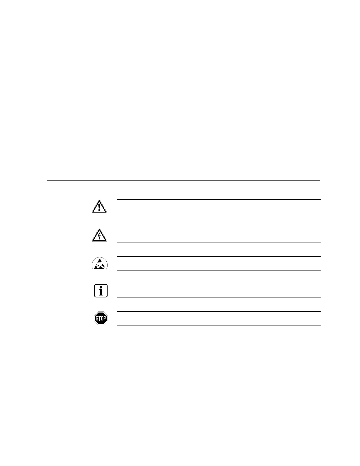
2.4 Meaning of the hazard symbols
The nature of the hazard is indicated by icons.
Dangerous situation
Electrical voltage
External voltage
Ground the component before making contact.
Tips and information
Important operating step or action
For example: the system, components or controls must be at zero potential.

Directives and standards
12
Siemens Building Technologies
Fire Safety & Security Products 01.2008
3 Directives and standards
This equipment has been tested and found to comply with the limits for a Class A
digital device, pursuant to Part 15 of the FCC Rules. These limits are designed to
provide reasonable protection against harmful interference when the equipment is
operated in a commercial environment. This equipment generates, uses, and can
radiate radio frequency energy and if not installed and used in accordance with the
Instruction Manual, may cause harmful interference to radio communications.
Operation of this equipment in a residential area is likely to cause harmful
interference, in which case users will be required to correct the interference at their
own expense.
CAUTION
Changes or modifications not expressly approved by the party responsible for compliance could void
the user's authority to operate the equipment.
This class of digital apparatus meets all requirements of the Canadian interferencecausing equipment regulations.
National standards
The products are developed and manufactured according to all applicable
European safety standards. Any national or local safety standards or laws that
apply to the development, design, installation, operation or disposal of a product
must be adhered to in addition to the instructions in the product documentation.

Technical data
13
Siemens Building Technologies
Fire Safety & Security Products 01.2008
4 Technical data
SISTORE MX 3204 SISTORE MX 3208 - 3232
with 4 video inputs with 8, 16 or 32 video inputs
SISTORE MX 3204 SISTORE MX 3208 - 3232
Recording speed - analog max. 50 images per second,
configurable for analogue cameras
max. 100 images per second,
configurable for analogue cameras
Recording speed - digital max. 100 images per second, configurable for max. 32 LAN cameras
Video inputs 4 x CCVS (BNC sockets) enabled,
1 V
pp
/75 Ohm, max. 32 LAN cameras
8/16/32 x CCVS (BNC sockets) enabled,
1 Vpp/75 Ohm, max. 32 LAN cameras
Outputs 1 x VGA, 2 x CCVS (BNC sockets) 1 x VGA, 4 x CCVS (BNC sockets)
Trigger inputs
16 U
in
: 5 – 24 V, max. 10 mA 32 Uin: 5 – 24 V, max. 10 mA
Event control event-triggered recording of individual cameras or camera groups with
configurable time-slot pattern. Events:
z alarm contacts
z motion detection
z Time control
z TCP/IP command
Alarm signalling via monitor connection, digital output, LAN/WAN to RemoteView station
Digital inputs 4 for AND operations and system control
Uin: 5 – 24 V, max. 10 mA
8 for AND operations and system control
U
in
: 5 – 24 V, max. 10 mA
Digital outputs 8 alarm/key outputs,
configurable switching (rising or falling
edge duration)
U
out
5 – 24 V, max. 50 mA
16 alarm/key outputs,
configurable switching (rising or falling
edge duration)
U
out
5 – 24 V, max. 50 mA
Interfaces 2 x RS485, 1 x LAN, 4 x USB 2.0 (0.5 A), 1 x SCSI,
1 x VGA, 1 x Audio in, 1 x Mic in, 1 x Audio out,
optionally: S
0
interface for ISDN
Mouse, PC keyboard mouse with USB connection, virtual keyboard activated, USB keyboard (optional)
Video standard PAL/NTSC
Resolution standard: 352 x 288 pixels,
high resolution: 704 x 288 pixels
Compression M-JPEG, configurable: variable between 10 and 80 KB
Text overlay in the video image max. 16 characters
Font and background colours freely selectable
Storage media basic unit (E)IDE

Technical data
14
Siemens Building Technologies
Fire Safety & Security Products 01.2008
SISTORE MX 3204 SISTORE MX 3208 - 3232
Memory capacity 250/500/750/1000 GB data memory
External storage media via network connection
Display resolution 1024 x 768, 1280 x 1024
Playback individual images, video sequence (replay rate configurable between 0.1 to 50
times), forward/backward, pause (frozen image)
Image search by means of date, time, camera number, recording event, graphic activity search,
logbook, Smartsearch
Video display formats 1x1, 2x2, 1 + 5, 3x3, 2 + 8, 4 + 9, 4x4, 6x6 - 4 (32), 7x7 – 1 (48), 8x8 (64)
System self-monitoring function hardware/software watchdog
Power supply 100 – 230 V AC, 50 – 60 Hz, approx. 120 W
Power input appliance inlet
Temperature range (operation) 5 – 35 °C
Design embedded
Environmental temperature 5 – 45 °C
Rel. humidity 20 – 80 % without condensation
Dimensions (W x H x D) 430 x 87 x 370 mm

Details for ordering
15
Siemens Building Technologies
Fire Safety & Security Products 01.2008
5 Details for ordering
As of Q2 2007 SISTORE MX is available in seven models:
Type Part no. Designation Weight
Without DVD
SISTORE MX 3208 250/200 S24245-F5085-A2 Hybrid recorder, 8 analog cameras,
32 network cameras, 250 GB,
100 ips analog, 100 ips digital
11.0 kg
SISTORE MX 3216 500/200 S24245-F5085-A4 Hybrid recorder, 16 analog cameras,
32 network cameras, 500 GB,
100 ips analog, 100 ips digital
11.0 kg
SISTORE MX 3232 1000/200 S24245-F5085-A6 Hybrid recorder, 32 analog cameras,
32 network cameras, 1000 GB,
100 ips analog, 100 ips digital
11.0 kg
With DVD
SISTORE MX 3204 250/150
DVD
S24245-F5085-A1 Hybrid recorder, 4 analog cameras,
32 network cameras, 250 GB,
50 ips analog, 100 ips digital, with DVD
11.0 kg
SISTORE MX 3208 250/200
DVD
S24245-F5085-A3 Hybrid recorder, 8 analog cameras,
32 network cameras, 250 GB,
100 ips analog, 100 ips digital, with DVD
11.0 kg
SISTORE MX 3216 500/200
DVD
S24245-F5085-A5 Hybrid recorder, 16 analog cameras,
32 network cameras, 500 GB,
100 ips analog, 100 ips digital, with DVD
11.0 kg
SISTORE MX 3232 1000/200
DVD
S24245-F5085-A7 Hybrid recorder, 32 analog cameras,
32 network cameras, 1000 GB,
100 ips analog, 100 ips digital, with DVD
11.0 kg
All SISTORE MX models have enabled video output and SCSI functions and are
delivered without keyboard.
SISTORE MX accessories (not included in the delivery):
Type Part no. Designation Weight
Activation of 4 SISTORE MX
video inputs
S24245-P5097-A4 Enables an additional 4 analog video inputs ./.
Activation of 8 SISTORE MX
video inputs
S24245-P5097-A1 Enables an additional 8 analog video inputs ./.
19“ installation kit for
SISTORE
MX/CX
C24245-A12-D2 Mounting equipment for installation in a 19“ rack 4.0 kg

Details for ordering
16
Siemens Building Technologies
Fire Safety & Security Products 01.2008
Software update to on
SISTORE MX memory stick
S24245-P5097-A5 The memory stick can be used directly on the USB
interface for the update
./.
MX multichannel box
(GAA/ATM)
S24245-F5092-A1 For connection of cash dispensers,
cash box or access control systems
1.2 kg
SISTORE MX hard drive
expansion kit 250 GByte
2GF4811-8CD For the expansion of SISTORE MX as of V2.50 0.8 kg
SISTORE MX hard drive
expansion kit 500 GByte
S24245-B5093-A1 For the expansion of SISTORE MX as of V2.50 0.8 kg
SISTORE RAID8 2000 S24245-B5108-A1 2 TB RAID system 34.8 kg
SISTORE RAID8 3000 S24245-B5108-A2 3 TB RAID system 38.4 kg
USBOBTO8 2GF4811-8CH USB-input module – 8 channels with optocoupler
function
./.
USBREL8 2GF4811-8CG USB output module - 8 channels with relay
function
./.
USBOPTOREL16 2GF4811-8CJ USB input and output modules with 16
optocoupler inputs and 16 relay outputs
./.
USB ISDN module 2GF4811-8FC For use on the SISTORE MX 0.8 kg
SISTORE MX USB mouse A5Q00009353 As a replacement device
SISTORE MX USB keyboard A5Q00009346 For SISTORE MX without keyboard
External USB DVD burner GBQ:S80817 For SISTORE MX without internal DVD burner
CMTC1525 TFT monitor 2GF3124-8AA 15-inch TFT colour monitor for CCTV 6.0 kg
CMTC1725 TFT monitor 2GF3125-8AA 17-inch TFT colour monitor for CCTV 6.5 kg
CMTC1925 TFT monitor 2GF3126-8AA 19-inch TFT colour monitor for CCTV 7.0 kg
Interface converter
RS232C/RS485
2GF5505-8AH Interface converter RS232C/RS485 0.1 kg
Converter model 4855DSR ./. From roline (please order directly from the
manufacturer)
./.
Converter model USB/RS232 ./. From roline (please order directly from the
manufacturer)
./.
KeBin access reader ./. From KEBA (please order directly from the
manufacturer)
./.
Miniter access reader ./. From STM GmbH (please order directly from the
manufacturer)
./.
Multimedia Control Panel
(ShuttlePRO2)
./. From Contour Design Ltd. (please order directly
from the manufacturer)
./.
The part number will be found on the rating plate on the bottom of the unit.
Fig. 1 Rating label

Scope of delivery
17
Siemens Building Technologies
Fire Safety & Security Products 01.2008
6 Scope of delivery
z SISTORE MX
z Mouse
z Mains cable
z 8 x digital I/O connector (SISTORE MX 3204)
z 14 x digital I/O connector (SISTORE MX 3208 - 3232)
z Activation form
z CD with the SISTORE MX application software and complete documentation
Prerequisites
18
Siemens Building Technologies
Fire Safety & Security Products 01.2008
7 Prerequisites
7.1 Hardware requirements
SISTORE MX integrates a video compression board (or frame grabber) that
features up to 16 (MX 3204) / 32 (MX 3232 - 3208) video inputs, depending on the
model.
SISTORE MX 3204 SISTORE MX 3208 - 3232
4 video inputs 8, 16, 32 video inputs
The video data is stored on local hard disks. Saving on optical CD-R/CD-RW odrr
DVD-R/DVD-RW drives is possible directly from SISTORE MX (see Section
17.16.2: Burning image sequences to CD/DVD).
7.2 Resolution and file format
The files stored by SISTORE MX have the extension .AVI or .k26. The resolution of
the stored images is (by using normal resolution) 352 x 288 pixel and (by using
high resolution) 704 x 288 pixel.
NOTE:
From version 2.35 on, SISTORE MX saves all files as *.k26 files instead of *.avi files. The SISTORE
player makes no difference between these two file types. The *.k26 files can however not be
reproduced using other movie player models (data protection of the SISTORE MX video files).
The user should therefore always copy the file „SISTOREPlayer.exe“ from the Windows directory (e.g.
\Windows) to the target data medium (disk, CD-R/CD-RW, DVD-R/DVD-RW or network drive) using
the Windows explorer. This ensures that the exported files can be reproduced using the SISTORE
player. Alternatively, since Version 2.45, the data can be stored without data protection as *.avi files
which can be played with standard movie player. For detailed information about data protection see
Section
17: Playback.
7.3 Conversion
As of version 2.35, SISTORE MX automatically converts the configurations of the
preceding version to the current version. Nevertheless, we would like to emphasize
that you should check your configuration without fail after an update.
NOTE:
A conversion of older versions (earlier than version 2.35) is not possible. It is also not possible to take
over settings for event-triggered recordings and scenarios from the preceding versions (earlier than
version 2.55). These are deleted during the conversion.

Operating modes
19
Siemens Building Technologies
Fire Safety & Security Products 01.2008
8 Operating modes
There are three operating modes:
z Display mode
z Playback mode
z Configuration mode
8.1 Display mode
After starting SISTORE MX, you will be in display mode. From here, after
successful login to the system, it is possible to access the configuration and
playback modes, insofar as you have the appropriate user authorisation to do so.
“Display mode” is intended for operating or surveillance staff while the system is in
operation. The cameras and all incoming events are displayed and recorded here.
It is also used for flexible live surveillance of all cameras.
8.2 Playback mode
The playback and/or revision of recordings is carried out in this mode. It is based
on an extremely high performance database and allows fast and easy tracking of
received alarms and their respective video sequences with all relevant additional
information. It is also possible to save important pictures in currently used formats
or even whole video sequences as “evidence“. Access to the “playback mode” is
only possible with the “Playback“ user authorisation.
8.3 Configuration mode
All system settings are defined in this mode (please refer to the Configuration
Manual). The opportunity exists to issue user authorisations (see Section
11 User
rights ). The configuration of the system and the “display mode” as well as the
definition of recording modes can be defined here. As recording modes can be
chosen:
z long-time recording with or without motion detection
z event-triggered recording with pre-alarm history and alarm memory.
This ensures that the system can be flexibly adapted to cover the widest possible
range of applications. Access to the “configuration mode” is restricted to users with
the “Configuration“ authorisation.
Getting started
20
Siemens Building Technologies
Fire Safety & Security Products 01.2008
9 Getting started
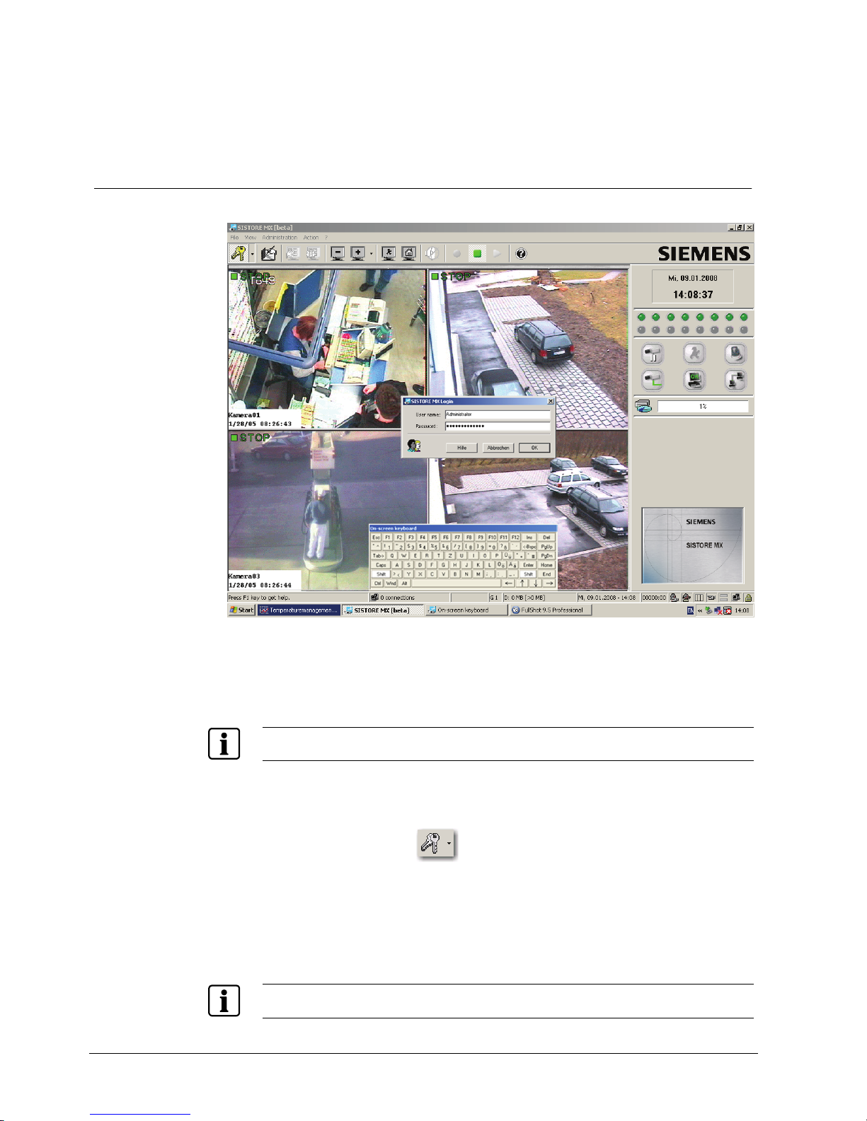
9.1 Software operation using the virtual keyboard
Fig. 2 Password entry using the virtual keyboard
As of Q2 2007 SISTORE MX 32xx is delivered without keyboard. Entry of the
characters of the password and parameter setting can be made using the virtual
keyboard.
NOTE
Alternatively, a USB keyboard is available as an option (see Section
5: Details for ordering).
1. Connect the mouse supplied to a USB port.
2. Switch the device on.
Î The SISTORE MX application software will be started automatically.
3. Click the Login icon
.
Î The virtual keyboard will appear.
4. Enter the password by clicking the appropriate letters and characters on the
virtual keyboard.
5. Click OK or press the Enter key.
Î The system is now ready for operation.
NOTE
Entries into all other input fields of the system are made in the same manner.
Getting started
21
Siemens Building Technologies
Fire Safety & Security Products 01.2008
9.2 Login
NOTE:
Without a successful login only the SISTORE MX online help will be available; all other functions will
not be available. Without a successful login it is also not possible to end the program.
Prerequisite
z The SISTORE MX application software has been started.
You have the following options to log into the system:
1. Select the menu option
File -> Login.
– OR –
Click the button
in the toolbar.
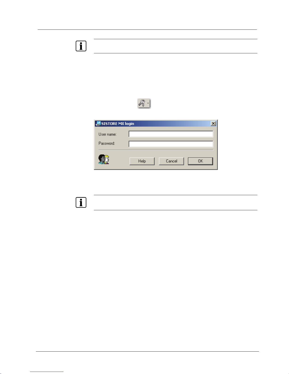
Î The following dialog box opens:
Fig. 3 SISTORE MX login
2. Enter your user name and password in the appropriate text fields.
NOTE
Your user name and password will be created for you by your administrator. The entry of user name
and password is case-sensitive.
3. Click OK.
Î You are logged into the system.

Getting started
22
Siemens Building Technologies
Fire Safety & Security Products 01.2008
Login via the drop-down menu
1. Click the arrow to the right of the button
.
Î A drop-down menu will open.
NOTE
The drop-down menu displays the user names of the last 5 successful registrations. This function is
not available when you log in for the first time.
2. Select the desired user name.
Î The SISTORE MX login dialog opens (see Fig. 3).
3. Enter the
password.
4. Click
OK.
Î You are logged into the system.
NOTE
Every time a user attempts to log into SISTORE MX, the following information is recorded in the
logbook:
z User name
z Time of the login
z Information on whether or not the user was granted access to SISTORE MX
The password is not stored.
Getting started
23
Siemens Building Technologies
Fire Safety & Security Products 01.2008
9.3 Program window
The program is started automatically when the device is started.
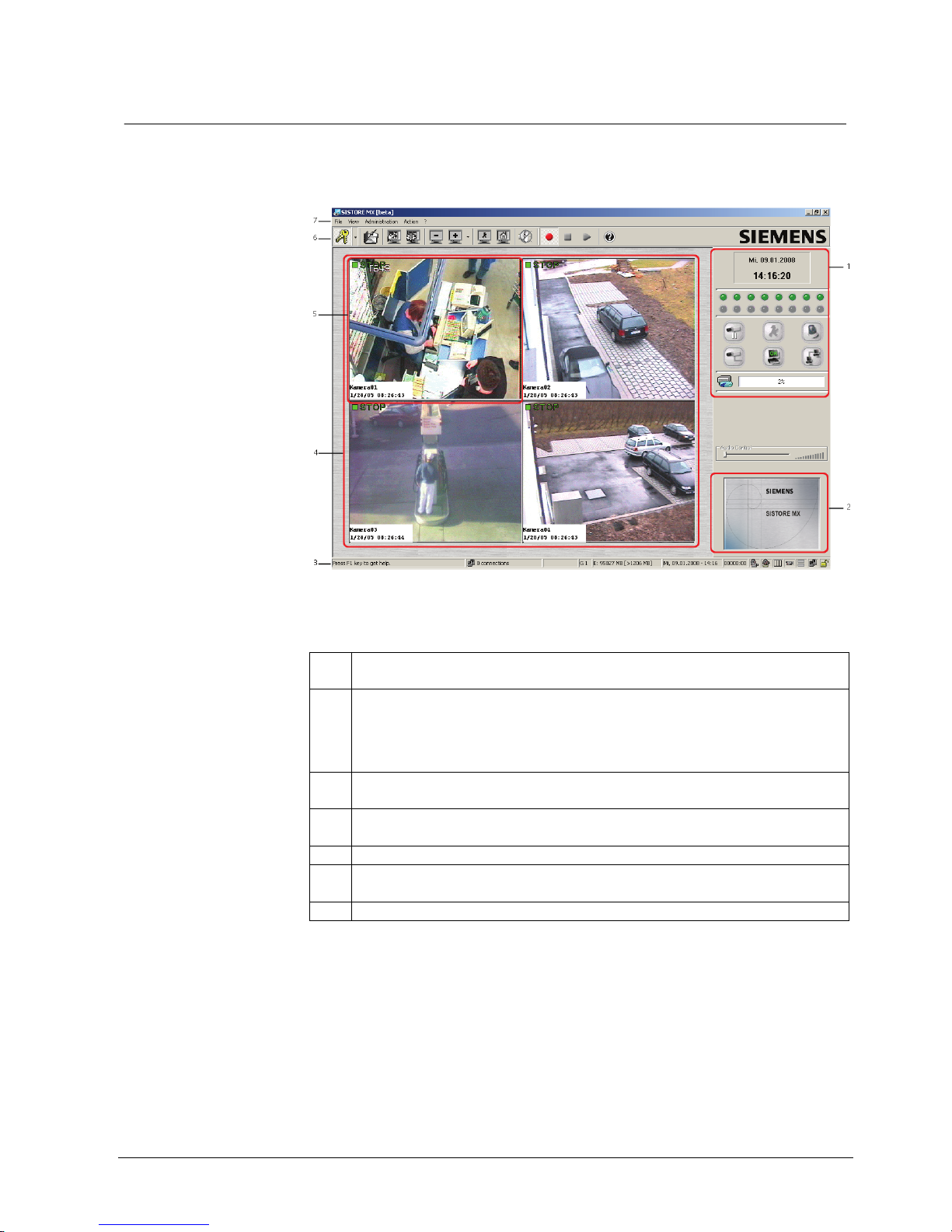
Î After the SISTORE MX is started the program window appears:
Fig. 4 SISTORE MX start dialog
The SISTORE MX program window consists of the following components:
1 System condition and system information
See Section
9.7: Video image display modes
2 Start frame
The start frame for the application is displayed insofar as no PTZ camera is available or the
registered user does not have authorisation for controlling a PTZ camera. See Section
16.2Camera PTZ control.
The start frame is also available if no user is registered.
3 Status bar
See Section
9.5: Status bar.
4 Video display area
See Section
9.6: Video display area.
5 Camera window
6 SISTORE MX tool bar
See Section
9.4: Toolbar.
7 Menu bar
After SISTORE MX is started you will automatically be in “display mode”. This
mode is the control centre. This is where all cameras are displayed and the output
of all alarm and status signals takes place.
Following first start, SISTORE MX enters all local hard disks on the list of the disks
to be used for recording. The partition where the operating system is installed is
removed from the list automatically.
Network drives are not added to the list automatically.
Getting started
24
Siemens Building Technologies
Fire Safety & Security Products 01.2008
When starting SISTORE MX for the first time, all analogue cameras found by an
automatic check of video inputs should be displayed. If this is not the case, one of
the following reasons is possible:
z an error occurred during the installation of SISTORE MX
z the connection of the cameras to SISTORE MX is faulty (connector not plugged
in properly)
z the camera is not sending any signal
In the first case, you should contact your installer.
9.4 Toolbar
The software functions can be called up by selecting the appropriate button in the
SISTORE MX toolbar.
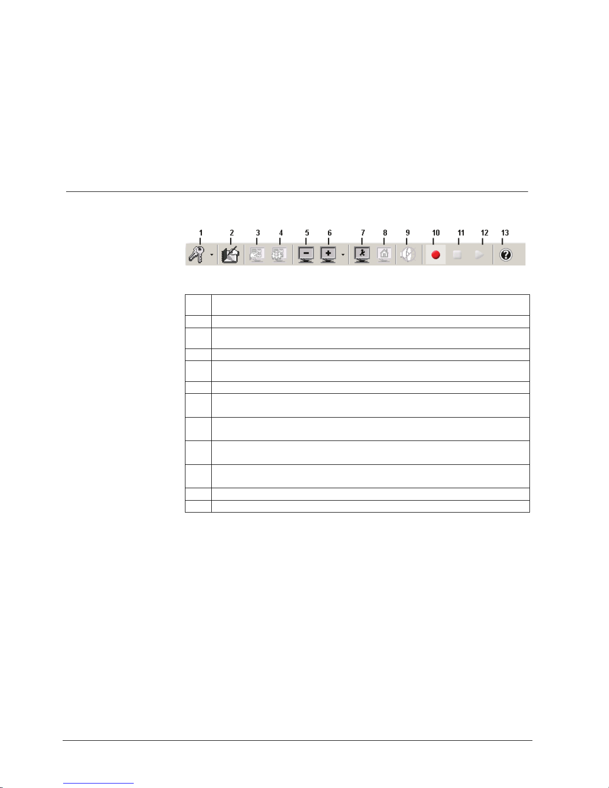
Fig. 5 SISTORE MX toolbar
1 Login
See Section
9.2 Login.
2 View logbook
3 Next group
See Section
10.11 Display camera group .
4 Automatic scan
5, 6 Video display modes
See Section
9.7: Video image display modes
7 Show event window
8 Show map
See Section
10.12 Site plan
9 Audio on/off
See Section
10.2 Audio on/off
10 Start recording: Starting the recording
See Section
12 Starting and stopping recording
11 Stop recording: Stopping the recording
See Section
12 Starting and stopping recording
12 Playback: Starting playback.
13 Online help
Getting started
25
Siemens Building Technologies
Fire Safety & Security Products 01.2008
9.5 Status bar
At the bottom of the screen you will find a status bar. You can switch this on or off
with the help of the menu
View -> Status line visible/invisible. On the playback or
configuration level, however, the system information is not visible, i.e. in this case
the status line represents the only source of information.
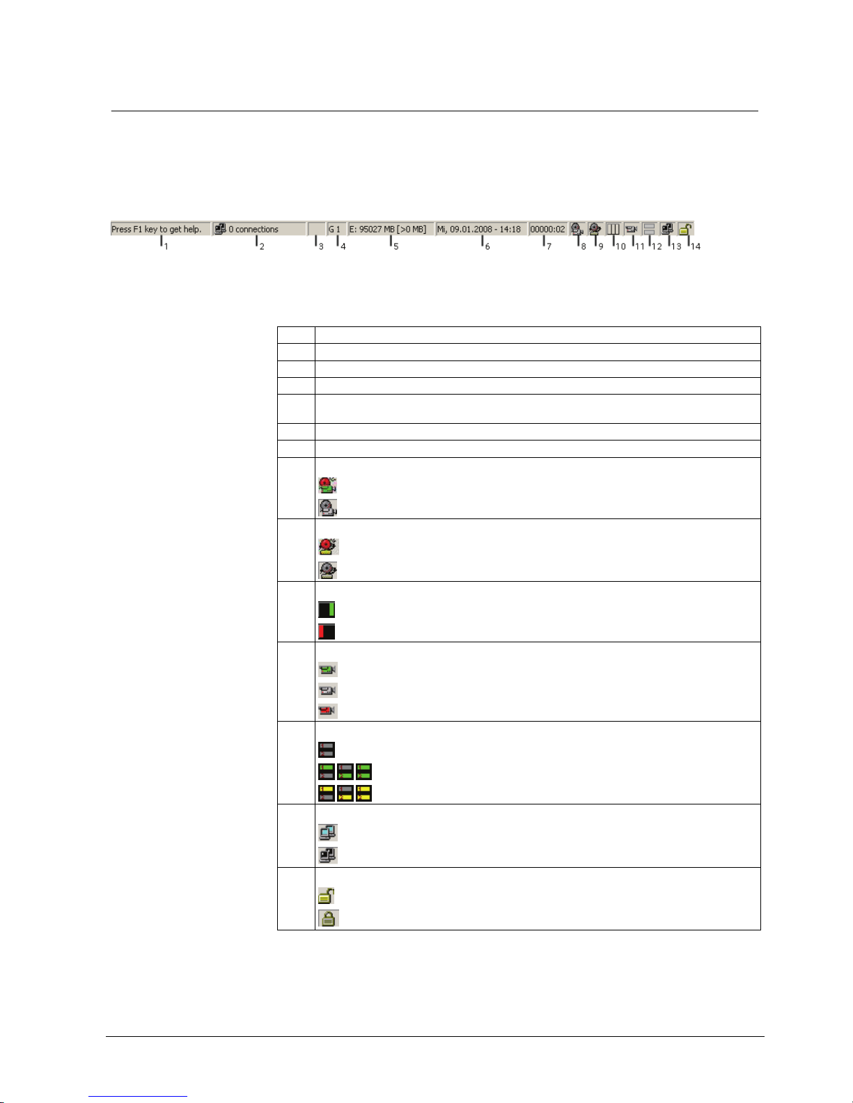
Fig. 6 Status bar
The status bar is divided into 14 fields (see
Fig. 6). The meaning of the fields is as
follows:
1 Brief help text to the menus (Windows standard)
2 Number of active connections
3 Connection speed
4 Currently displayed camera group
5 Free storage space of drive(s) being used and the minimum required free space (see below in
this section)
6 Date and time
7 Application running time in hours and minutes
8 Symbol showing whether a camera has detected a motion
Motion detected
No motion detected
9 Symbol showing whether SISTORE MX is currently recording an alarm
Alarm
No alarm
10 Status indication of the tamper detection
Tamper detection active – no tampering detected.
At least one camera has detected a tamper event.
11 Symbol showing a recording activity or a fault in hardware
(blinking green) Hardware OK, recording in progress
(grey) Hardware OK, no recording activity
(red) Fault in hardware
12 ISDN connection.
Channel 1 and Channel 2 are not busy
Channel 1/Channel 2 is busy, connection is set up.
Dial-up of Channel 1/Channel 2
13 Symbol indicating the connection status of the RemoteView.
There is at least one active connection with a RemoteView PC
There is no active connection with a RemoteView PC
14 Login/logout symbol showing the user status
User logged in
No user logged in

Getting started
26
Siemens Building Technologies
Fire Safety & Security Products 01.2008
The available disk capacity is shown in four stages in the status line, two of these
are shown as a graph display.
Stage 1: The disk capacity which is already occupied is shown as a percentage
in the form of a blue bar.
Stage 2: As stage 1, but showing the estimated remaining recording time. This is
an estimate because the system does not display the actual remaining
recording time but, instead, measures the data volume that can still be
saved and displays it as an estimated available remaining recording
time. The system uses the actual settings (frame rate, image size) as a
basis for this estimate.
Stage 3: Shows in text form the designation of the hard disk where current
recording is taking place, the disk's available capacity and its maximum
capacity.
Stage 4: Shows in text form the available capacity and the maximum capacity of
all hard disks authorised for recording.
The display form set last is stored and used automatically again when SISTORE
MX is restarted. This does not apply to SISTORE MX RemoteView.
RemoteView status displays
There are several server-related status displays on the RemoteView. In multiserver mode, the server whose status is to be displayed must be selected in the list
of cameras.
The status displays always relate to the server that is associated with the selected
camera.
The server-related status displays include:
z Time
z Alarm outputs
z HDD capacity indicator
z Recording duration
z Start/stop of recording
Global status displays for all servers include:
z Motion
z Alarm
z Loss of video
z Camera tamper
z Error
z Connection
Getting started
27
Siemens Building Technologies
Fire Safety & Security Products 01.2008
9.6 Video display area
In display mode all camera pictures are each located within one window. Each
window has a pre-set size and position. The number of visible camera windows
depends on the configuration and the chosen order of the windows. Only those
cameras are displayed which have been configured in the configuration mode
and released for display. The name of the camera, date and time may also be
displayed within the camera picture. Position and colour for these text titles can be
set in the configuration mode.
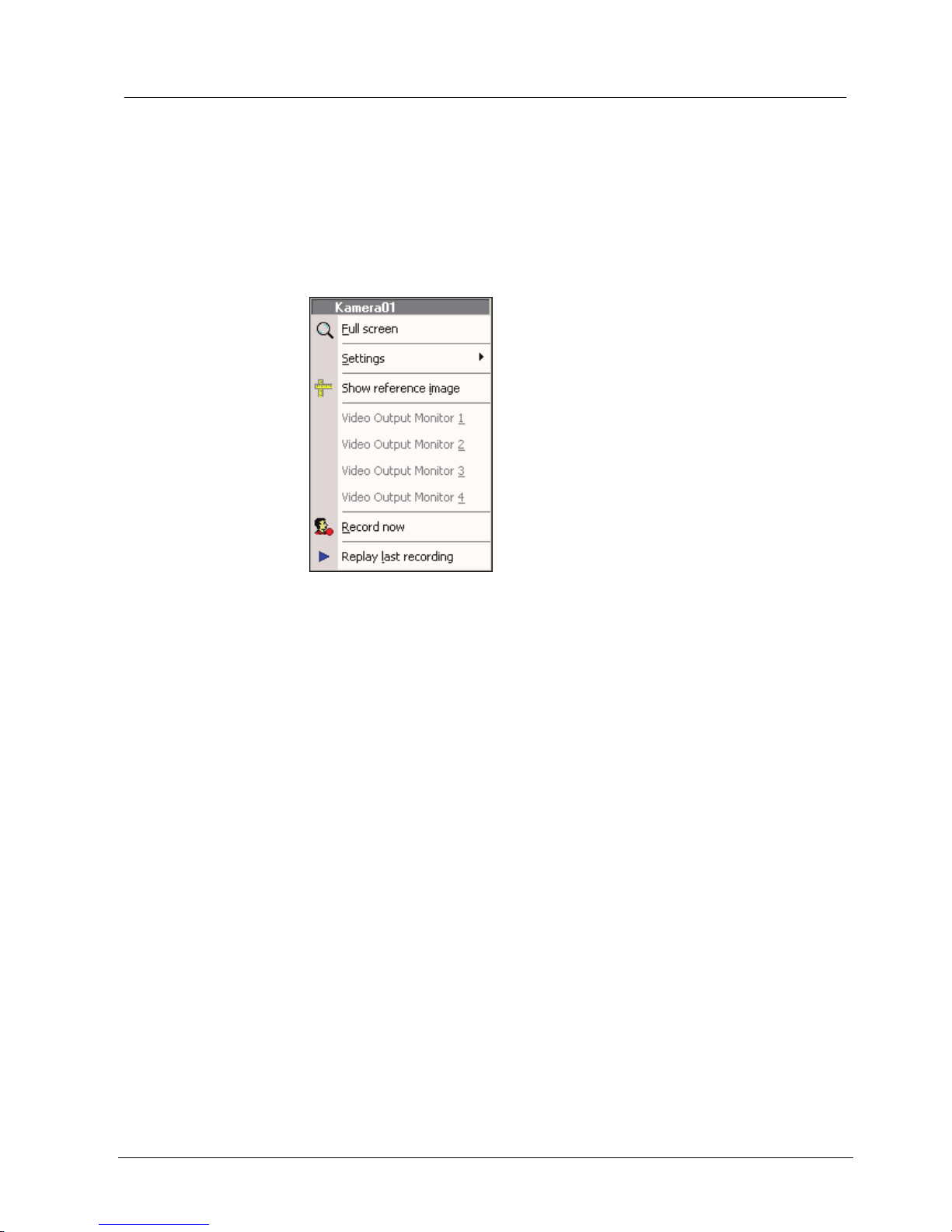
Right-clicking on a camera window will open the appropriate context menu. This
context menu offers additional options.
Fig. 7 Context menu in the video display area
Getting started
28
Siemens Building Technologies
Fire Safety & Security Products 01.2008
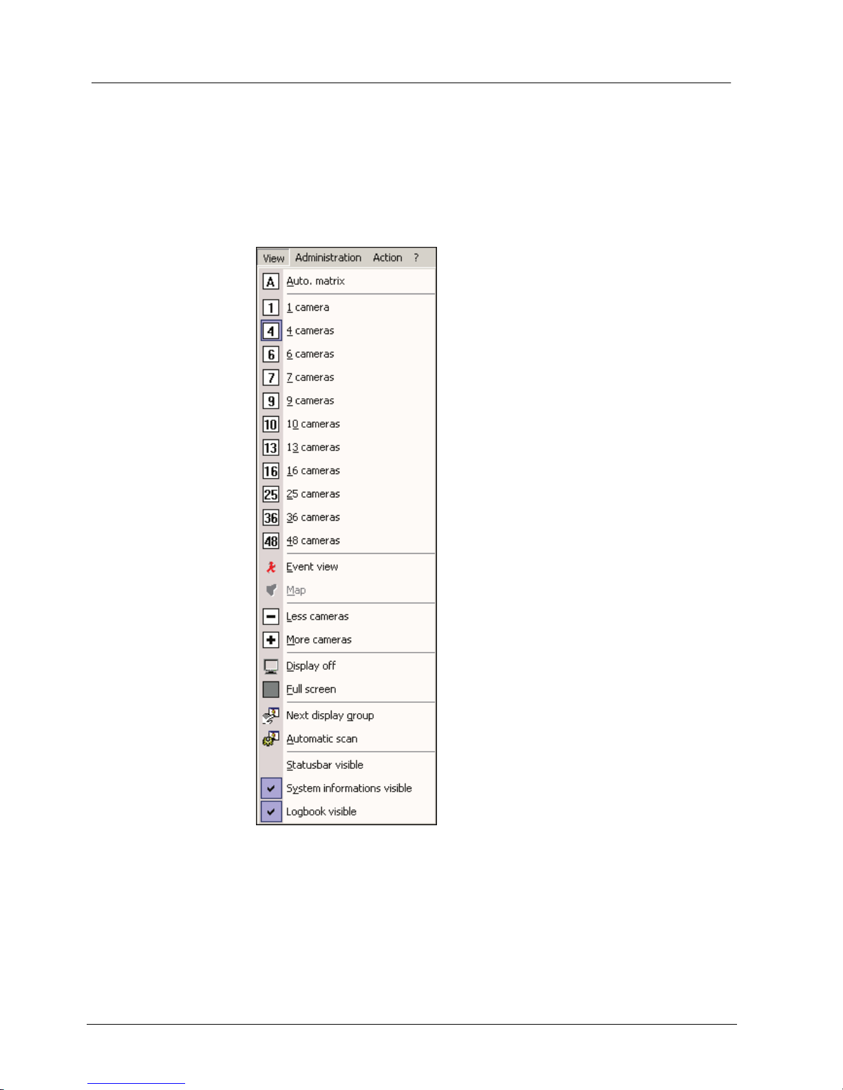
9.6.1 Toggle video display area
By selecting View -> Display off in the display mode you can switch the video
display area on and off even if a user is currently logged on.
Prerequisite:
z You are logged into SISTORE MX and the display mode is opened.
1. Select Display off or Display on in the View menu .
Î The video display area is switched off or on.
Fig. 8 "View" menu
Getting started
29
Siemens Building Technologies
Fire Safety & Security Products 01.2008
9.6.2 Toggle full screen mode
Each camera window can be enlarged.
1. Right-click on the corresponding video image in the video display area.
Î The context menu will open.
2. Select
Full screen in the context menu.
– OR –
Double click the left mouse button on the corresponding video image.
Î The video image is displayed in full screen mode.
Return to normal screen:
1. Double click the left mouse button on the camera picture displayed in full
screen mode.
Î The video image is displayed in the normal screen mode.
NOTE
The size of the video image is limited by the size of the camera window. If the picture supplied by the
camera is larger than the display area, it will be scaled down to an appropriate size so it can be
displayed in the camera window. Only one camera window can be enlarged at a time.
9.7 Video image display modes
You can choose how many camera windows will be displayed simultaneously in
the video display area.
The camera windows are displayed equally in a 1-, 4-, 9-, 16-, 25-, 32- and 64-split.
Using the 6-, 7-, 10- and 13-split, the windows are displayed in different sizes.
NOTE
Adjustments are possible depending on the respective hardware being used; for instance if your HVR
systems is an 8-channel model, then only 8 cameras will be displayed in the 9-split display.
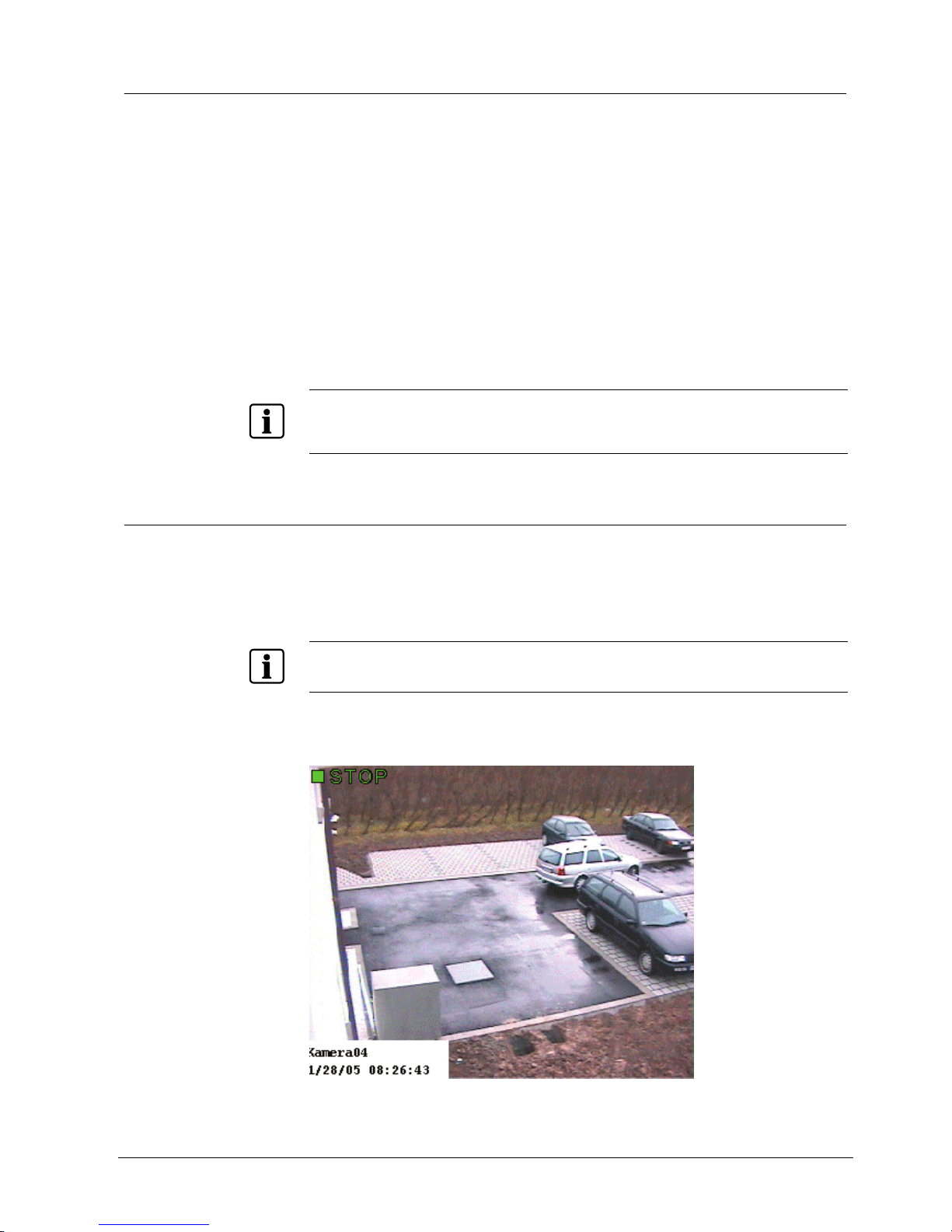
Different acronyms are displayed in the video frame at top left to identify the mode
of operation (see
Fig. 9).
Fig. 9 SISTORE MX camera window
Getting started
30
Siemens Building Technologies
Fire Safety & Security Products 01.2008
The meaning of the acronyms is as follows:
Acronym Meaning
STOP Camera image is only displayed
DET Motion detection is activated
REC Camera is recording
PTZ (yellow) The camera has pan/tilt and zoom functions and is currently active. The window of
an active PTZ camera has yellow edging.
PTZ (grey) The camera has PTZ function, but is not active, i.e. the PTZ function is not being
applied to this camera.
DISP The live image of a LAN camera is displayed.
9.7.1 Changing the number of cameras shown
Prerequisites:
z The SISTORE MX application software has been started.
z You are logged into SISTORE MX..
(See Section
9.2: Login)
z
1. Select the desired menu option
X cameras in the View menu.
Î The selected number of cameras are shown in the video display area.
Increase or reduce the number of cameras shown
1. Click either
or in the toolbar.
Î The number of cameras shown is increased or reduced.
The window split is defined within the “configuration mode”, which is automatically
active after starting SISTORE MX.
9.7.2 Enlarging camera windows
Each camera window can be enlarged and displayed centrally.
1. Right-click on the corresponding video image in the video display area.
Î The context menu will open.
2. Select
Full screen in the context menu.
– OR –
Double click the left mouse button on the corresponding video image.
Î The video image is displayed in full screen mode.
Return to normal screen
1. Double click the left mouse button on the camera picture displayed in full
screen mode.
Î The video image is displayed in the normal screen mode.
NOTE
The size of the video image is limited by the size of the camera window. If the picture supplied by the
camera is larger than the display area, it will be scaled down to an appropriate size so it can be
displayed in the camera window. Only one camera window can be enlarged at a time.
 Loading...