

Siemens SISTORE AX9 250, SISTORE AX9 200, SISTORE AX16 250, SISTORE AX16 200 User Manual
Fire Safety & Security Products
Siemens Building Technologies
Digital Video Recorder
SISTORE AX9 250/200 V3.5
SISTORE AX16 250/200 V3.5
User Manual

Liefermöglichkeiten und technische Änderungen vorbehalten.
Data and design subject to change without notice. / Supply subject to availability.
© 2007 Copyright by
Siemens Building Technologies AG
Wir behalten uns alle Rechte an diesem Dokument und an dem in ihm dargestellten Gegenstand vor. Der Empfänger erkennt diese Rechte
an und wird dieses Dokument nicht ohne unsere vorgängige schriftliche Ermächtigung ganz oder teilweise Dritten zugänglich machen oder
außerhalb des Zweckes verwenden, zu dem es ihm übergeben worden ist.
We reserve all rights in this document and in the subject thereof. By acceptance of the document the recipient acknowledges these rights
and undertakes not to publish the document nor the subject thereof in full or in part, nor to make them available to any third party without our
prior express written authorization, nor to use it for any purpose other than for which it was delivered to him.
Disclaimer
We have taken every possible care in preparing this manual. The contents of this
manual are revised regularly and brought up to latest standards. Nevertheless, we
are unable to provide any guarantee with regard to content, entirety or quality of
the details contained in this manual.
No liability can be assumed for direct or consequential losses and third-party
damages arising from the purchase of this product. In all cases, liability is limited to
the purchase price of the product.
The information in these operating instructions was up to date at the time of
publication. We reserve the right to make subsequent changes to technical or
organizational details. Siemens assumes no liability for problems resulting from the
use of this manual. The information contained in this document may be changed
without prior notice. Siemens reserves the right to publicize any such changes by
issuing updated versions or new editions.
Copyright
Copyright © 2007 Siemens Fire & Security Products. All rights reserved.
Siemens Fire & Security Products confers upon the purchaser the right to use the
software.
This manual may not be copied, reproduced, transcribed or translated into another
language in part or full without our written consent.
Trademarks
SISTORE is a trademark of Siemens Fire & Security Products.
Microsoft is a registered trademark and Windows a trademark of Microsoft
Corporation. All other products or company names referred to explicitly in this
manual are mentioned only for purposes of identification and/or description and
may be trademarks or registered trademarks of their respective owners.
Contacting us
If you have questions or suggestions regarding this product or this documentation,
please contact your local SIEMENS representative. You can also visit our Web site
at http://www.siemens.com/sistoreax
.
Training courses
Siemens Fire & Security Products provides training courses for all products.

3
Siemens Building Technologies
Fire Safety & Security Products 03.2007
About this document
This User Manual contains instructions for installation, configuration and operation
of SISTORE AX. A complete version of this manual can be found in Adobe Acrobat
format (PDF) on the SISTORE AX CD. This is the most recent version, unless
changes have been made after the printing of this manual. All subsequent
alterations have been included as far as possible.

4
Siemens Building Technologies
Fire Safety & Security Products 03.2007

5
Siemens Building Technologies
Fire Safety & Security Products 03.2007
Contents
1 Safety .......................................................................................................9
1.1 Target readers...........................................................................................9
1.2 Work safety information ..........................................................................10
1.2.1 Transport.................................................................................................10
1.2.2 Installation and setup ..............................................................................11
1.2.3 Software installation................................................................................13
1.2.4 Operation ................................................................................................13
1.2.5 Service and maintenance .......................................................................13
1.3 Meaning of the hazard symbols..............................................................13
2 Guidelines and standards ....................................................................14
2.1 EU Directive ............................................................................................14
2.2 UL and FCC compliance.........................................................................14
3 Technical data .......................................................................................15
4 Details for ordering...............................................................................17
5 Scope of delivery ..................................................................................17
6 Description of functions.......................................................................18
7 Installation .............................................................................................20
7.1 Connecting the video input .....................................................................21
7.2 Connecting the loop-through video.........................................................21
7.3 Connecting the monitor...........................................................................21
7.4 Connecting a VGA monitor .....................................................................22
7.5 Connecting audio ....................................................................................22
7.6 Connecting alarms ..................................................................................23
7.7 Connecting to the RS485 port.................................................................24
7.8 Connecting to the USB ports ..................................................................24
7.9 Connecting to the RS232 port.................................................................25
7.10 Connecting to the UltraWide SCSI port ..................................................25
7.11 Connecting to the network port...............................................................26
7.12 Factory reset ...........................................................................................26
7.13 Connecting the power cord .....................................................................27
8 Configuration.........................................................................................28
8.1 Front panel controls ................................................................................28
8.2 Turning on the power ..............................................................................31
8.3 Initial unit setup .......................................................................................31
8.4 Setup screen...........................................................................................32
8.5 Recording settings ..................................................................................33
8.5.1 Record screen.........................................................................................33
8.5.2 Schedule screen .....................................................................................35
8.5.3 Pre-Event screen ....................................................................................37
8.5.4 Archive screen ........................................................................................38
8.6 Network setup .........................................................................................40
8.6.1 Network screen .......................................................................................40
8.6.2 LAN setup screen....................................................................................43
8.6.3 Modem setup ..........................................................................................46

6
Siemens Building Technologies
Fire Safety & Security Products 03.2007
8.7 Event settings..........................................................................................47
8.7.1 Alarm-In screen.......................................................................................47
8.7.2 Motion Detection screen .........................................................................50
8.7.3 Video Loss screen...................................................................................54
8.7.4 Text-In screen .........................................................................................56
8.7.5 System Event screen ..............................................................................60
8.7.6 Event status.............................................................................................64
8.8 Display.....................................................................................................65
8.8.1 OSD screen.............................................................................................65
8.8.2 Main Monitor screen................................................................................66
8.8.3 Spot Monitor screen ................................................................................67
8.9 Configuring devices.................................................................................68
8.9.1 Camera setup screen..............................................................................68
8.9.2 Audio setup screen .................................................................................70
8.9.3 Alarm-Out screen ....................................................................................71
8.9.4 Remote Control screen ...........................................................................72
8.10 Storage screen........................................................................................73
8.10.1 Storage Information screen.....................................................................73
8.10.2 Storage Status screen.............................................................................75
8.11 System ....................................................................................................76
8.11.1 Information screen ..................................................................................76
8.11.2 Date/Time setup......................................................................................79
8.11.3 User setup screen ...................................................................................81
8.11.4 Shutdown… screen.................................................................................83
8.11.5 Log out…screen......................................................................................84
9 Operation ...............................................................................................85
9.1 Turning on the power ..............................................................................85
9.2 Live monitoring........................................................................................85
9.2.1 Active Cameo mode................................................................................86
9.2.2 PIP mode.................................................................................................86
9.2.3 Zoom mode .............................................................................................86
9.2.4 PTZ mode................................................................................................87
9.2.5 Image adjustment....................................................................................89
9.3 Event monitoring .....................................................................................90
9.4 Covert camera.........................................................................................90
9.5 Spot monitoring .......................................................................................91
9.6 Using a mouse ........................................................................................92
9.7 Recording video ......................................................................................93
9.8 Recording audio ......................................................................................94
9.9 Playing recorded video............................................................................94
9.10 Searching video ......................................................................................96
9.10.1 Go to the Date/Time................................................................................97
9.10.2 Calendar Search .....................................................................................97
9.10.3 Event Log Search....................................................................................98
9.10.4 Text-In Search.......................................................................................100
9.10.5 Motion Search .......................................................................................102
9.10.6 Clip-Copy screen...................................................................................104
9.10.7 Print screen ...........................................................................................106
10 Troubleshooting..................................................................................107
11 Disposal ...............................................................................................108

7
Siemens Building Technologies
Fire Safety & Security Products 03.2007
12 Appendix..............................................................................................109
12.1 Preparing the USB-IDE hard disk drive in Windows 2000.................... 109
12.2 Reviewing video clips............................................................................110
12.3 Time overlap .........................................................................................112
12.4 Recording tables ...................................................................................113
12.4.1 Recording times with 250 GB HDD (days) for PAL images..................113
12.4.2 Recording times with 250 GB HDD (days) for NTSC images...............114
12.5 Connector pin outs................................................................................115
12.6 Connection diagrams ............................................................................ 116
12.6.1 Connecting SISTORE AX to Remote Administration Software (RAS)
via dial-up connection (PSTN or ISDN) ................................................116
12.6.2 Connecting the remote keyboard CKA4820 and dome cameras
CCDA1415 and CCDA1425/1435.........................................................117
12.6.3 Connecting alarm input/output..............................................................118
12.7 Map of screens......................................................................................119
12.8 System log notices................................................................................120
12.9 Error code notices.................................................................................121

8
Siemens Building Technologies
Fire Safety & Security Products 03.2007

Safety
9
Siemens Building Technologies
Fire Safety & Security Products 03.2007
1 Safety
1.1 Target readers
The instructions in this document are designed only for the following target
readers:
Target readers Qualification Activity
Installation
personnel
Professional training in the
field of building automation or
electrical installations.
They install product, device or
system components and
subsequently carry out a general
performance check.
Commissioning
personnel
They have had the
professional training
appropriate to their function
and to the commissioning of
the products, systems and
devices and have attended the
technical training courses for
commissioning personnel.
The configuration of the products,
devices or systems for specific
customers at the place of
installation.
They check serviceability and
officially clear the product, device or
system for use by the operator /
customer.
They are also responsible for
trouble-shooting
Product specialist Has suitable technical training
for the function and operation
of the product and has
attended the technical training
courses for product specialists
provided by the manufacturer.
Programs and adjusts the product
parameters for country or customerspecific requirements. Provides
support for solving technical
problems. Provides support for any
product malfunction or failure which
may arise.
Operator Competence in reading and
comprehension of the
instructions contained in the
documentation under the
heading "Operation". No
particular previous knowledge
or training is required, although
an instruction by qualified
personnel may be necessary.
Performs only the procedures for
proper operation of the device.
Maintenance staff Is suitably trained for the
function and operation of the
product.
Performs all maintenance work
described in the product
documentation and checks for
correct functioning of the
equipment.

Safety
10
Siemens Building Technologies
Fire Safety & Security Products 03.2007
1.2 Work safety information
WARNING
To reduce the risk of electric shock, do not remove cover (or back). No userserviceable parts inside. Refer servicing to qualified service personnel.
– Read the general safety precautions before operating the device.
– Follow all warnings and instructions marked on the device.
– Keep this document for reference.
– Always pass this document on together with the device.
Burn hazard
– Do not touch the housing of the device while it is in operation.
Radio interference with other devices in the environment
– This is a Class A device. This equipment may cause radio interference in a
residential installation. In this case the user is encouraged to perform
appropriate measures to correct the interference.
Liability claim
– Do not connect the device if any parts are missing or damaged.
– Do not make any changes or modifications to the device that are not mentioned
in this manual and that have not been approved by the manufacturer.
– Use only spare parts and accessories that have been approved by the
manufacturer. Unauthorized substitutions may result in fire, electric shock or
other hazards.
1.2.1 Transport
Damage during transport
– Keep the packaging material for future transportation.
– Do not expose the device to mechanical vibrations or shocks.

Safety
11
Siemens Building Technologies
Fire Safety & Security Products 03.2007
1.2.2 Installation and setup
Accessories
– Do not place this equipment on an unstable cart, stand or table. The equipment
may fall, causing serious injury to a child or adult, and serious damage to the
equipment. Wall or shelf mounting should follow the manufacturer's instructions,
and should use a mounting kit approved by the manufacturer. Do not misplace
this equipment other than upright position. This equipment has an open frame
SMPS (Switching Mode Power Supply), which may cause a fire or electric shock
if anything is inserted into the unit through the ventilation holes on the side of the
equipment.
– This equipment and cart combination should be moved with care. Quick stops,
excessive force, and uneven surfaces may cause the equipment and cart
combination to overturn.
Attachments
– Never add any attachments and/or equipment without the approval of the
manufacturer as such additions may result in the risk of fire, electric shock or
other personal injury.
Field installation
– This installation should be made by a qualified service person and should
conform to all local codes.
Correct batteries
– Warning: Risk of explosion if battery is replaced by an incorrect type. Dispose of
used batteries according to the instructions.
Cable damage due to mechanical load
– When connecting the cables, do not apply tensile force and make sure not to
bend or damage them.
Overheating due to lack of ventilation
– Do not block or cover ventilation openings.
Damage due to unsuitable mounting location
– The environmental conditions recommended by the manufacturer must be
observed. See Section: 3: Technical data.
– Elevated Operating Ambient Temperature
If installed in a closed or multi-unit rack assembly, the operating ambient
temperature of the rack environment may be greater than room ambient.
Therefore, consideration should be given to installing the equipment in an
environment compatible with the manufacturer’s maximum rated ambient
temperature (Tmra).

Safety
12
Siemens Building Technologies
Fire Safety & Security Products 03.2007
– Reduced Air Flow
Installation of the equipment in the rack should be such that the amount of
airflow required for safe operation of the equipment is not compromised.
– Mechanical Loading
Mounting of the equipment in the rack should be such that a hazardous
condition is not caused by uneven mechanical loading.
– Do not use this equipment near water or in contact with water.
– Do not operate the device close to sources of powerful electromagnetic
radiation.
– Do not operate the device in excessively dusty places.
– Do not operate the device where it is exposed to mechanical vibrations.
Damage to the device due to overvoltage
– This equipment should be operated only from the type of power source indicated
on the marking label. If you are not sure of the type of power, please consult
your equipment dealer or local power company..
– For additional protection of this equipment during a lightning storm, or when it is
left unattended and unused for long periods of time, unplug it from the wall outlet
and disconnect the antenna or cable system. This will prevent damage to the
equipment due to lightning and power-line surges.
– Do not overload wall outlets and extension cords as this can result in the risk of
fire or electric shock.
Risk of failure of the main device
– Power cables to the main device are to be run separately and have a dedicated,
clearly labelled fuse.
Dangerous situation due to false alarm
– Make sure to notify all relevant parties and authorities providing assistance
before testing the system.
– To avoid panic, always inform all those present before testing any alarm
devices.
Danger of electrical shock and damage to the device
– Electrical grounding must meet the customary local safety regulations.
Danger of electrical shock due to insufficient labelling
– Make sure the device is permanently connected to the electricity supply; a
readily accessible disconnect device must be provided.
Liability claim
– For reasons of electromagnetic compatibility RS232, USB, audio in/out and
power supply cables must not exceed 3 meters length.

Safety
13
Siemens Building Technologies
Fire Safety & Security Products 03.2007
1.2.3 Software installation
Data loss after update
– Make sure to backup all data before updating the device.
1.2.4 Operation
Electric shock or fire hazard
– Never insert objects through the openings on the device.
– Never spill liquid of any kind on the equipment.
1.2.5 Service and maintenance
– Always unplug this equipment from the wall outlet before opening it (the
integrated power supply unit is not shielded).
– Do not attempt to service this equipment yourself. Refer all servicing to qualified
service personnel.
– Damage requiring Service
Unplug this equipment from the wall outlet and refer servicing to qualified service
personnel under the following conditions:
– When the power-supply cord or the plug has been damaged.
– If liquid is spilled, or objects have fallen into the equipment.
– If the equipment has been exposed to rain or water.
– If the equipment does not operate normally by following the operating
instructions, adjust only those controls that are covered by the operating
instructions as an improper adjustment of other controls may result in damage
and will often require extensive work by a qualified technician to restore the
equipment to its normal operation.
– If the equipment has been dropped, or the cabinet damaged.
– When the equipment exhibits a distinct change in performance — this
indicates a need for service.
– Upon completion of any service or repairs to this equipment, ask the service
technician to perform safety checks to determine that the equipment is in proper
operating condition:
Danger of electrical shock while cleaning the device
– Unplug this equipment from the wall outlet before cleaning it.
– Do not use liquid aerosol cleaners. Use a damp soft cloth for cleaning.
1.3 Meaning of the hazard symbols
The nature of the hazard is indicated by icons.
Dangerous situation

Guidelines and standards
14
Siemens Building Technologies
Fire Safety & Security Products 03.2007
2 Guidelines and standards
2.1 EU Directive
The product meets the requirements of the EU Directive 89/336/EEC on
electromagnetic compatibility The EU declaration of conformity is available from:
Siemens Building Technologies
Fire & Security Products GmbH & Co. oHG
76181 Karlsruhe, Germany
EU Directive 89/336/EEC on electromagnetic compatibility
Conformity with the EU Directive 89/336/EEC is demonstrated by compliance with
the following standards:
Emitted interference: EN 61000-6-4
EN 55022 Class A
Resistance to interference: EN 50130-4
EU Directive 73/23/EEC „Low-Voltage Directive”
Compliance with the European Directive 73/23/EEC has been proven by testing
according to the following standard:
Safety: EN 60950-1
2.2 UL and FCC compliance
This product complies with the requirements of the Standards
UL 2044 Commercial Closed-Circuit Television Equipment
and
FCC Part 15 – radio frequency devices Class A digital device.
FCC information
This equipment has been tested and found to comply with the limits for a Class A
digital device, pursuant to Part 15 of the FCC Rules. These limits are designed to
provide reasonable protection against harmful interference when the equipment is
operated in a commercial environment.
This equipment generates, uses, and can radiate radio frequency energy and, if
not installed and used in accordance with the instruction manual, may cause
harmful interference to radio communications.
Operation of this equipment in a residential area is likely to cause harmful
interference in which case the user will be required to correct the interference at his
own expense. Shielded cables should be used with this unit to ensure compliance
with class A limits.

Technical data
15
Siemens Building Technologies
Fire Safety & Security Products 03.2007
3 Technical data
Video
Signal format PAL or NTSC (auto-detect)
Video input Composite: 9 or 16 looping inputs, 1 Vpp auto-terminating, 75 Ohms
Monitor outputs Composite: 1 (BNC), 1 Vpp, 75 Ohms
SVHS: 1
VGA: 1
- PAL: 30.8 kHz (horiz. frequency) / 50 Hz (vert. frequency)
- NTSC: 30.8 kHz (horiz. frequency) / 60 Hz (vert. frequency)
Video resolution PAL: 720 x 576
NTSC: 720 x 480
Playback/record speed
(images per second)
Standard resolution (CIF): 200 ips (PAL), 240 ips (NTSC)
High resolution (2CIF): 100 ips (PAL), 120 ips (NTSC)
Inputs / Outputs
Alarm input 9 or 16 TTL, programmable as NC or NO
Alarm output 9 or 16 TTL open collector, 5 mA @ 12 V / 30 mA @ 5 V
Alarm reset input 1x TTL
Internal buzzer 80 dB @ 10 cm
Network connectivity 10/100 Mbps Ethernet (RJ-45), RS-232C for external modem
Audio input RCA input: 4, Line In
Audio output RCA output: 1, Line Out
IR port 1 remote control
Connections
Video input Composite: 9 or 16 BNC
Video loop Composite: 9 or 16 BNC (auto-terminating)
Monitor output Composite: 1x BNC
SVHS: 1 Y/C *
VGA: 1 VGA
SPOT (composite): 4 BNC
Audio In 4 RCA connectors
Audio Out 1 RCA connector
Alarm input/output 16/16 push-button, terminal blocks
Ethernet port RJ-45
RS-232C serial port DB9 (P)
RS-485 serial port 2-connector terminal block
UltraWide SCSI port High-density female 68-pin connector
USB port 3 (USB 2.0)
Storage
Primary storage EIDE hard-disk drive (up to 3)
Built-in CD-RW or DVD-RW drive **
Secondary storage (optional) UltraWide SCSI hard-disk drive (RAID)
USB hard-disk drive, USB CD-RW drive or USB flash drive

Technical data
16
Siemens Building Technologies
Fire Safety & Security Products 03.2007
Environmental
Operating temperature 5 – 40 °C (41 – 104 °F)
Operating humidity 0 – 90%
Power supply
Power 100 - 240 V AC, 2 A, 50/60 Hz
Power consumption 85 W max. (120 W when 3 hard-disk drives are installed)
General
Dimensions (WxHxD) 430 x 88 x 405 mm (16.9" x 3.5" x 15.9")
Unit weight 10.2 kg (22.5 lbs)
Shipping weight 12.5 kg (27.6 lbs)
Shipping dimensions (WxHxD) 540 x 290 x 590 mm (21.3" x 11.4" x 23.2")
Approval
CE, UL, FCC, C-Tick
*) Using a shielded S-Video cable provides better quality video display and
reduces image noise.
**) When installing an internal CD-RW or DVD-RW drive, set the jumper to Master
and connect to the secondary IDE channel.
Specifications are subject to change without notice.

Details for ordering
17
Siemens Building Technologies
Fire Safety & Security Products 03.2007
4 Details for ordering
Type Order No. Designation Weight
SISTORE AX9 250/200 2GF4816-8EA SISTORE AX9, 250 GB, 200 ips (built-in CD-RW) 10.2 kg
SISTORE AX16 250/200 2GF4816-8FA SISTORE AX16, 250 GB, 200 ips (built-in CD-RW) 10.2 kg
SISTORE AX9 250/200 2GF4816-8EB SISTORE AX9, 250 GB, 200 ips (built-in DVD-RW) 10.2 kg
SISTORE AX16 250/200 2GF4816-8FB SISTORE AX16, 250 GB, 200 ips (built-in DVD-RW) 10.2 kg
5 Scope of delivery
z Digital video recorder
z Power cord
z User Manual, Multilingual RAS Software and User Manual on CD-ROM
z Multilingual Installation Guide
z Rack-mount kit
z Assembly screws guide rails for adding hard disk drives
z Screws for fixing SCSI connector
z Infrared remote control

Description of functions
18
Siemens Building Technologies
Fire Safety & Security Products 03.2007
6 Description of functions
SISTORE AX is a digital video recording system for the surveillance of rooms,
premises, buildings, production workshops, critical public areas or any outdoor
areas where security is important.
In addition to replacing both a time-lapse VCR and a multiplexer in a security
installation, your DVR has many features that make it much more powerful and
easier to use than even the most advanced VCR.
The DVR converts analog PAL or NTSC video to digital images and records them
on a hard disk drive. Using a hard disk drive allows you to access recorded video
almost instantaneously; there is no need to rewind tape. The technology also
allows you to view recorded video while the DVR continues recording video.
Digitally recorded video has several advantages over analog video recorded on
tape. There is no need to adjust tracking. You can freeze frames, fast forward, fast
reverse, slow forward and slow reverse without image streaking or tearing. Digital
video can be indexed by time or events, and you can instantly view video after
selecting the time or event.
Your DVR can be set up for event or time-lapse recording. You can define times to
record, and the schedule can change for different days of the week and user
defined holidays.
The DVR can be set up to alert you when the hard disk drive is full, or it can be set
to record over the oldest video once the disk is full.
Your DVR uses a proprietary encryption scheme making it nearly impossible to
alter video.
You can view video and control your DVR remotely by connecting via modem or
Ethernet. There is a SCSI port that can be used to record or archive video to
external hard disk drives, and there are also three USB ports that can be used to
upgrade the system or copy video clips to external hard disk, CD-RW and flash
drives.
NOTE
This manual covers the 9- and 16-channel digital video recorders. The DVRs are identical except for
the number of cameras and alarms that can be connected and the number of cameras that can be
displayed. For simplicity, the illustrations and descriptions in this manual refer to the 16-camera model.
Your colour digital video recorder (DVR) provides recording capabilities for nine or
16 camera inputs. It provides exceptional picture quality in both live and playback
modes, and offers the following features:
– Efficient video compression through “MPEG4 Technology“
– 9 or 16 composite video input connectors
– Compatible with colour (NTSC or PAL) and B/W (CCIR and EIA-170) video
sources
– Auto-detection for PAL and NTSC
– Multiple monitor connectors: 1 BNC Video Out, 1 SVHS, 4 Spot, 1 VGA

Description of functions
19
Siemens Building Technologies
Fire Safety & Security Products 03.2007
– Multiple search engines (date/time, calendar, event, motion, museum, text-in)
– Records up to 200/240 images per second (PAL/NTSC)
(high resolution 100/120)
– “Loop-through” video connectors
– Continuous recording in disk overwrite mode
– Video archiving via UltraSCSI interface
– 3 USB 2.0 ports
– Continues recording while archiving, transmitting to remote site and during
playback
– User-friendly Graphical User Interface (GUI) menu system
– Multiple recording modes (time-lapse, pre-event, alarm, motion and panic)
– 4-channel audio recording and 1-channel audio playback
– Text input for ATM and POS
– Alarm connections include: input, output and reset input
– Built-in alarm buzzer
– Live or recorded video access via Ethernet or modem
– Time synchronization using industry standard protocol
– Built-in CD-RW or DVD-RW drive
– Self-diagnostics with automatic notification including hard disk drive S.M.A.R.T.
protocol
– Infrared remote control
Installation
20
Siemens Building Technologies
Fire Safety & Security Products 03.2007
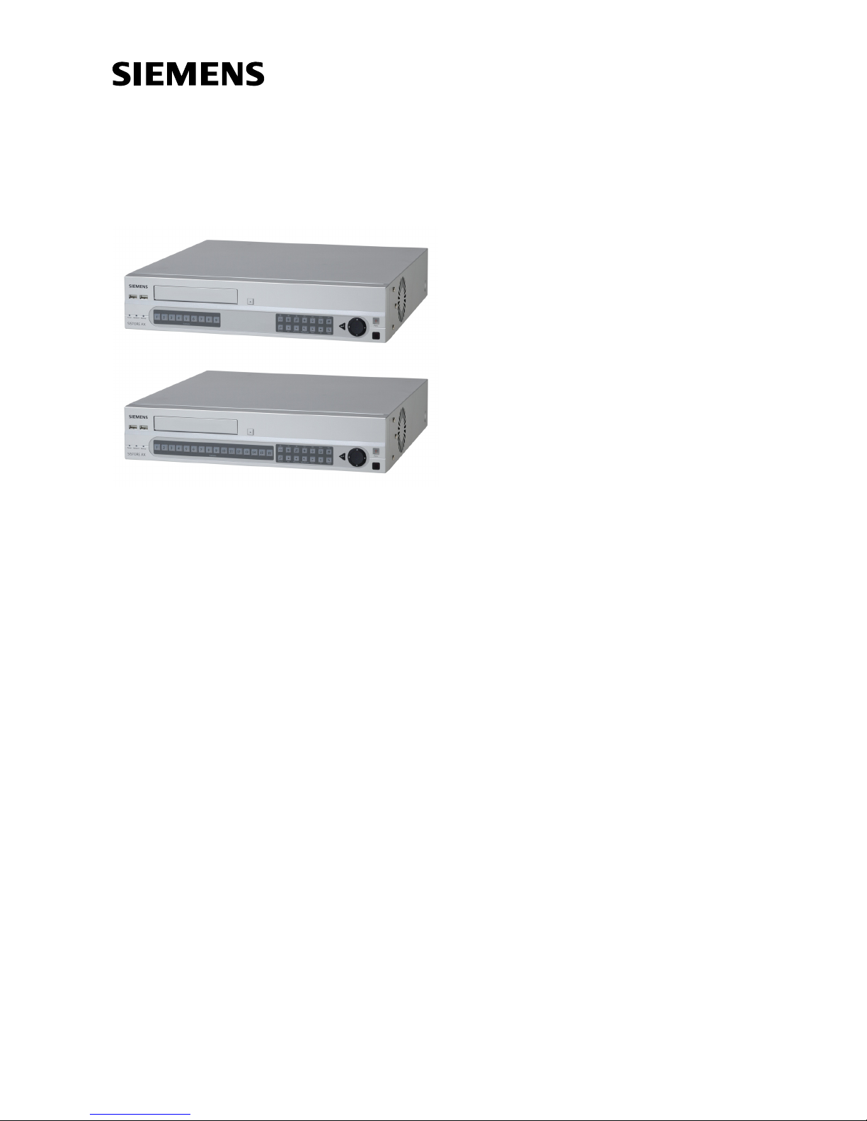
7 Installation
The diagram below shows a typical DVR installation.
Fig. 1 Typical DVR installation
No special tools are required to install the DVR. Refer to the installation manuals
for the other items that make up part of your system.
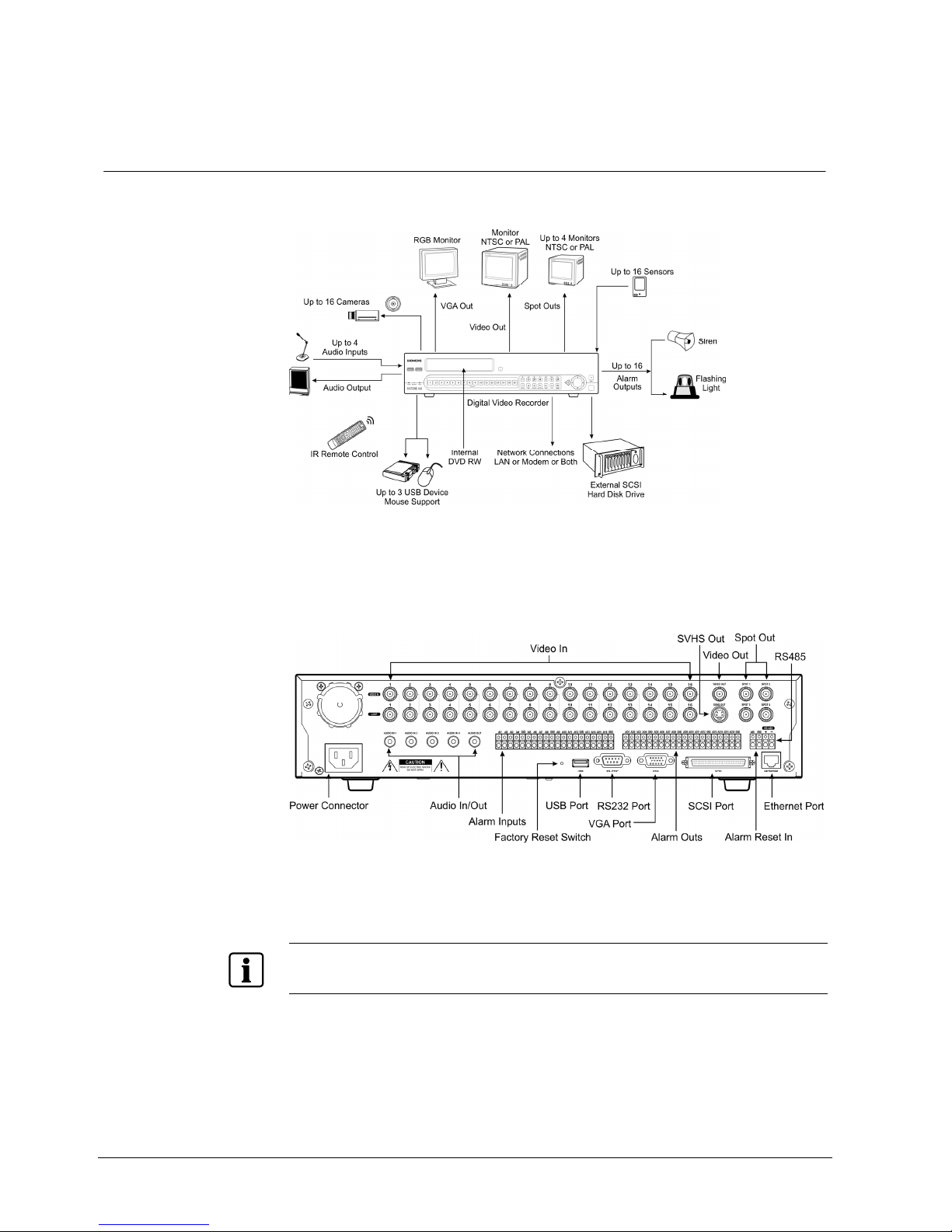
Fig. 2 16-channel DVR rear panel
Your DVR can be used with either PAL or NTSC equipment.
NOTE
You cannot mix PAL and NTSC equipment. For example you cannot use a PAL camera and an NTSC
monitor.
Installation
21
Siemens Building Technologies
Fire Safety & Security Products 03.2007
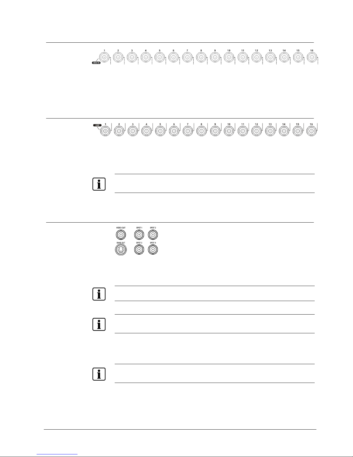
7.1 Connecting the video input
Fig. 3 Video input connectors
Connect the coaxial cables from the video sources to the BNC Video In
connectors.
7.2 Connecting the loop-through video
Fig. 4 Video loop-through connectors
If you would like to connect your video source to another device, you can use the
Loop BNC connectors.
NOTE
The Loop BNC connectors are auto terminated. Do not connect a cable to the Loop BNC unless it is
connected to a terminated device because it will cause poor quality video.
7.3 Connecting the monitor
Fig. 5 Video Out connectors
Connect the main monitor to either the Video Out or SVHS Out connector.
NOTE
If your main monitor has an SVHS input, use it because it will give you better quality video display.
NOTE
The Video Out (BNC) and SVHS Out connectors may be connected to individual monitors for
simultaneous operation.
Up to four Spot monitors can be connected to the DVR. Connect the spot monitors
to the SPOT 1, SPOT 2, SPOT 3 and SPOT 4 connectors as needed.
NOTE
When the DVR is in the Search mode, it can display live video on the SPOT 1 monitor as displayed on
the main monitor during the live mode.

Installation
22
Siemens Building Technologies
Fire Safety & Security Products 03.2007
7.4 Connecting a VGA monitor
Fig. 6 VGA connector
A VGA connector is provided so that you can use a standard, multi-sync computer
monitor as your main monitor. Use the cable supplied with your monitor to connect
it to the DVR.
NOTE
Please note the technical specification for the VGA output in Section 3: Technical data.
NOTE
Pressing and holding the Display button on the front panel for 5 seconds or longer will switch the video
output between Video Out (BNC or SVHS Out) and VGA Out. During clip copy, you cannot switch the
video output between Video Out and VGA Out.
NOTE
The DVR will not record video for about 3 seconds while switching the video output between Video
Out and VGA Out.
7.5 Connecting audio
NOTE
It is the user’s responsibility to determine if local laws and regulations permit recording audio.
Fig. 7 Audio In and Out connectors.
Your DVR can record audio from up to four sources. Connect the audio sources to
Audio In 1, Audio In 2, Audio In 3 and Audio In 4 as needed using RCA jacks.
Connect Audio Out to your amplifier.
NOTE
The DVR does not have amplified audio output, so you will need a speaker with an amplifier. The DVR
does not have a pre-amplifier for audio input, so the audio input should be from an amplified source,
not directly from a microphone.
Installation
23
Siemens Building Technologies
Fire Safety & Security Products 03.2007
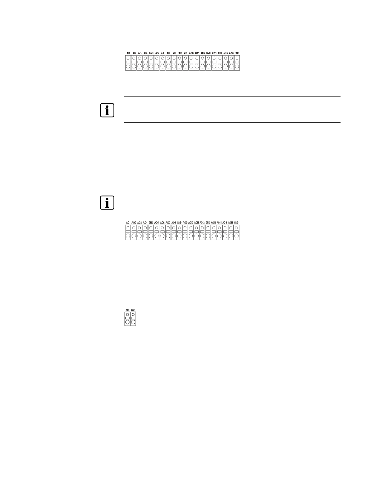
7.6 Connecting alarms
Fig. 8 Alarm Input connectors
NOTE
To make connections on the Alarm Connector Strip, press and hold the button and insert the wire in
the hole below the button. After releasing the button, tug gently on the wire to make certain it is
connected. To disconnect a wire, press and hold the button above the wire and pull out the wire.
AI 1 to 16 (Alarm-In) You can use external devices to signal the DVR to react to events.
Mechanical or electrical switches can be wired to the AI (Alarm-In) and
GND (Ground) connectors. The threshold voltage is 4.3 V and should be
stable at least 0.5 seconds to be detected. See Section 8.7.1: Alarm-In
screen.
GND (Ground) Connect the ground side of the alarm input and/or alarm output to the
GND connector.
NOTE
All the connectors marked GND are common.
Fig. 9 Alarm Output connectors
AO 1 to 16 (Alarm-Out) The DVR can activate external devices such as buzzers or lights. Connect
the device to the AO (Alarm-Out) and GND (Ground) connectors. AO is an
active low open collector output which sinks 5mA @ 12 V and 30 mA @
5 V. See Section 8.9.3: Alarm-Out screen.
ARI (Alarm Reset In)
Fig. 10 Alarm Reset Input connectors
An external signal to the Alarm Reset In can be used to reset both the Alarm Out
signal and the DVR’s internal buzzer. Mechanical or electrical switches can be
wired to the ARI (Alarm Reset In) and GND (Ground) connectors. The threshold
voltage is below 0.3V and should be stable at least 0.5 seconds to be detected.
Connect the wires to the ARI (Alarm Reset In) and GND (Ground) connectors.
Installation
24
Siemens Building Technologies
Fire Safety & Security Products 03.2007
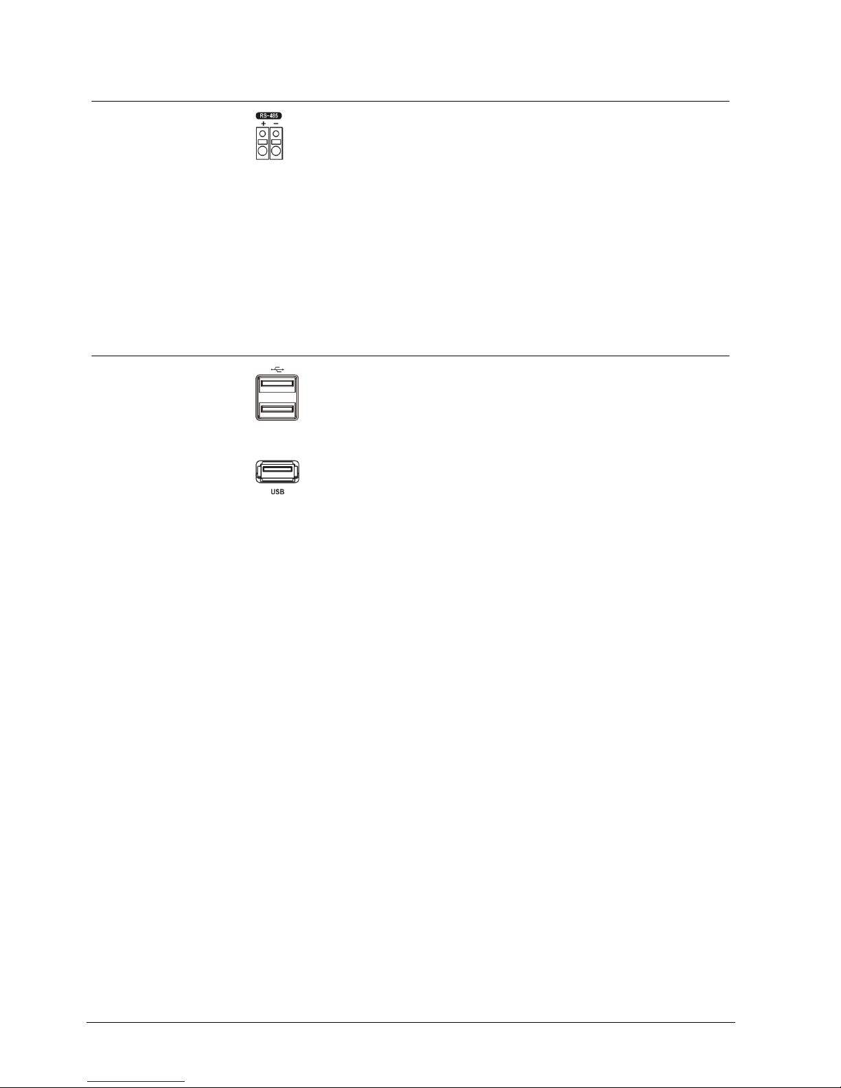
7.7 Connecting to the RS485 port
Fig. 11 RS485 connector
The DVR can be controlled remotely by an external device or control system, such
as a control keyboard, using RS485 half-duplex serial communications signals.
The RS485 connector can also be used to control PTZ (pan, tilt, zoom) cameras.
Connect RX-/TX- and RX+/ TX+ of the control system to the − and + (respectively)
of the DVR. See the Section 8: Configuration and the PTZ camera or remote
keyboard manual for configuring the RS485 connection.
7.8 Connecting to the USB ports
Fig. 12 Front USB connectors
Fig. 13 Rear USB connector
Three USB ports are provided to connect external hard disk, CD-RW or flash
drives for video clip copying or system upgrades. One USB port is on the rear
panel and the other two are on the front panel. Position external drives close
enough to the DVR so that you can make the cable connections, usually less than
6 feet. Use the USB cable provided with the hard disk drive to connect it to the
DVR.
A USB mouse (not supplied) can be connected to one of the ports. You can use
the mouse to navigate through the screens and menus much like you would on a
computer.
A PostScript™ USB printer (not supplied) can be connected to one of the ports.
You can print selected images resulting from a search. Refer to Section 9.10:
Searching video.
A USB to Serial converter can be connected to the USB port. Multiple text-in
devices can be used with a USB to Serial converter.
Installation
25
Siemens Building Technologies
Fire Safety & Security Products 03.2007
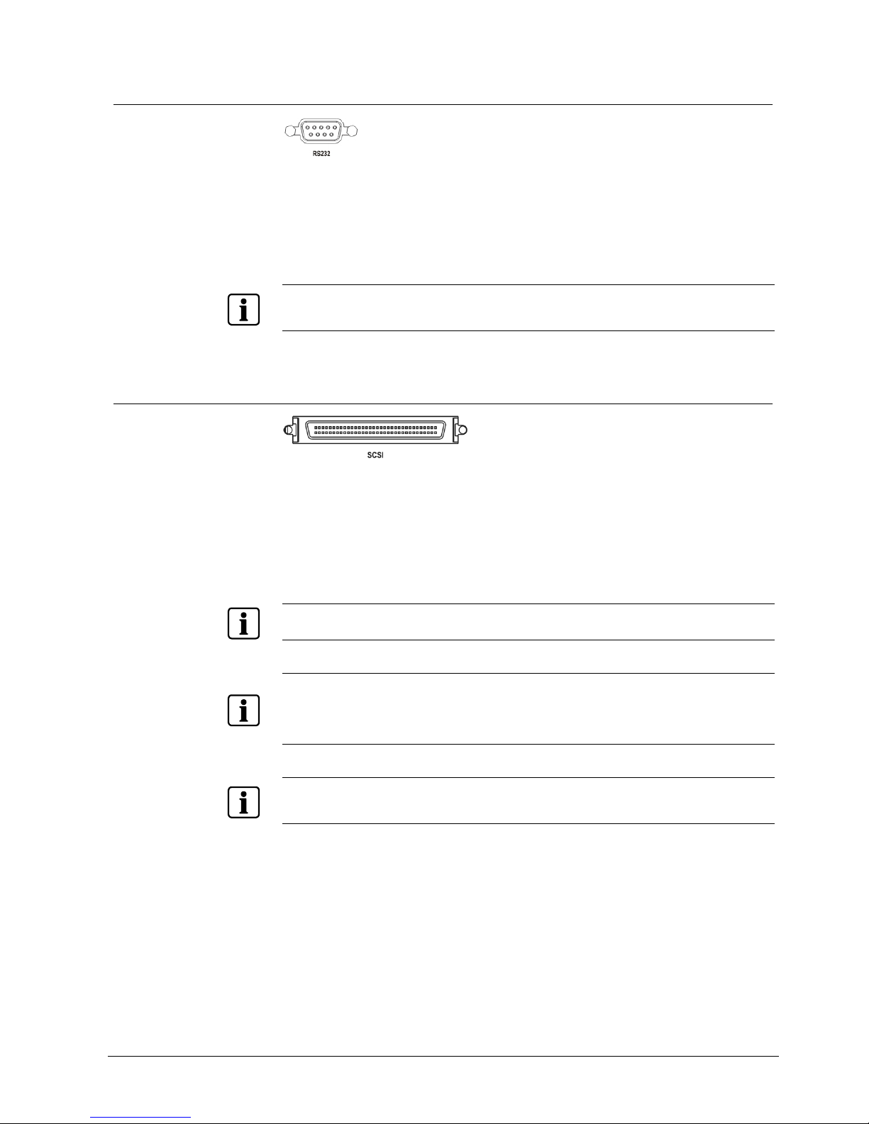
7.9 Connecting to the RS232 port
Fig. 14 RS232 connector
An RS232 port is provided to connect an external modem for remote monitoring,
configuration and software upgrades, and to connect a remote control keyboard.
Use a modem cable with a DB-9S (female) connector to connect to the DVR. See
Section 8: Configuration for configuring the modem.
NOTE
The DVR is not supplied with a modem cable, and many modems are not supplied with cables. Make
certain you have the correct cable when purchasing the modem.
7.10 Connecting to the UltraWide SCSI port
Fig. 15 SCSI connector
A SCSI port is provided to connect external storage devices for recording or
archiving video. Connect the external SCSI hard disk drive (RAID) cable to the
high-density 68-pin female UltraWide SCSI port. The length of SCSI cable should
not exceed1.5 meters (5 feet). You can connect up to 8 UltraWide SCSI devices
with SCSI IDs set from 0 to 15 except for 7, which is assigned as the Host ID.
NOTE
The SCSI bus must be terminated, otherwise the DVR will not operate properly.
NOTE
Do not connect or disconnect SCSI devices while the DVR power is on. The DVR must be powered
down to connect or disconnect SCSI devices. Power up SCSI devices so they are ready for operation
before powering up the DVR. Power down SCSI devices after powering down the DVR and then
disconnect SCSI devices.
NOTE
If the SCSI device is shut down while the device is operating, the DVR system might not operate
normally.
Installation
26
Siemens Building Technologies
Fire Safety & Security Products 03.2007
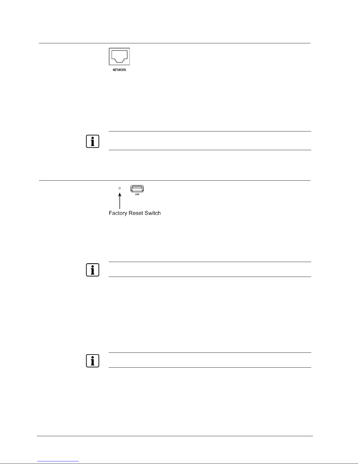
7.11 Connecting to the network port
Fig. 16 Network connector
The DVR can be networked using the 10/100Mb Ethernet connector. Connect a
Cat5 cable with an RJ-45 jack to the DVR connector. The DVR can be networked
with a computer for remote monitoring, searching, configuration and software
upgrades. See the Section 8: Configuration for configuring the Ethernet
connections.
NOTE
The Network connecter is not designed to be connected directly with cable or wire intended for
outdoor use.
7.12 Factory reset
Fig. 17 Factory reset switch
The DVR has a factory reset switch to the left of the USB port on the rear panel.
This switch will only be used on the rare occasions that you want to return all the
settings to the original factory settings.
NOTE
When using the Factory Reset, you will lose any settings you have saved.
To reset the unit, you will need a straightened paperclip:
1. Turn the DVR off.
2. Turn it on again.
Î While the DVR is initializing, the front panel LEDs will blink.
Î When any of the Camera 1 to 8 LEDs blink, poke the straightened paperclip in
the unlabeled hole to the left of the USB port.
3. Hold the switch until all the LEDs on the front panel are lit.
NOTE
When the DVR successfully resets to factory defaults all the LEDs on the front panel flash five times.
4. Release the reset switch.
Î All of the DVR’s settings are now at the original settings it had when it left the
factory.
Installation
27
Siemens Building Technologies
Fire Safety & Security Products 03.2007
7.13 Connecting the power cord
Fig. 18 Power cord connector
Connect the AC power cord to the DVR and then to a wall outlet.
NOTE
Route power cords so that they are not a tripping hazard. Make certain the power cord will not be
pinched or abraded by furniture. Do not install power cords under rugs or carpet.
NOTE
The power cord has a grounding pin. If your power outlet does not have a grounding pin receptacle,
do not modify the plug.
Do not overload the circuit by plugging too many devices in to one circuit.
Your DVR is now ready to operate. Refer to Sections 8: Configuration and
9: Operation.
Configuration
28
Siemens Building Technologies
Fire Safety & Security Products 03.2007
8 Configuration
NOTE
Your DVR should be completely installed before proceeding. Refer to Section 7: Installation.
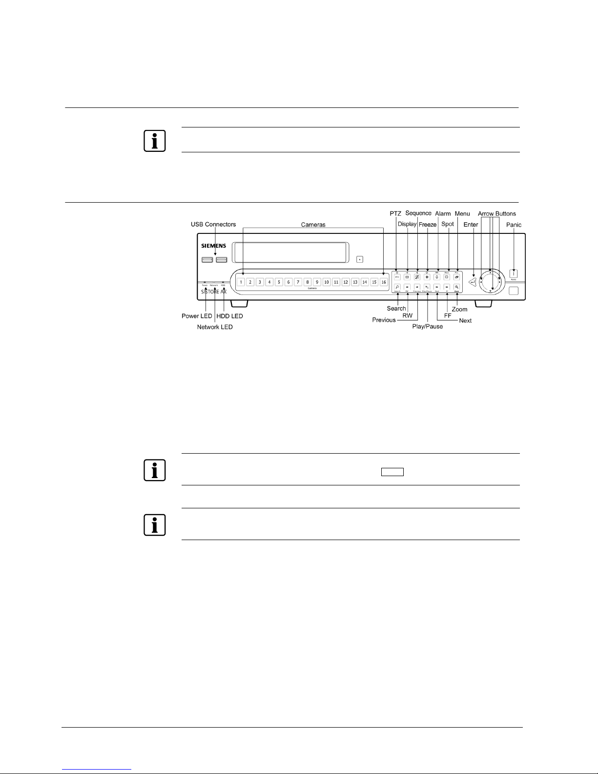
8.1 Front panel controls
Fig. 19 16-channel DVR front panel
The front panel looks and operates much like a VCR combined with a multiplexer.
Many of the buttons have multiple functions. The buttons on the infrared remote
control, while laid out differently, perform the same functions as those on the front
panel. The following describes each button and control. Take a few minutes to
review the descriptions. You will use these to initially set up your DVR and for daily
operations.
NOTE
The infrared sensor on the DVR is just to the lower left of the
PANIC button. Make certain that nothing
blocks the sensor, or the remote control will not function properly.
NOTE
You can also use a USB mouse (not supplied) to navigate through the screens and menus much like
you would on a computer.
Configuration
29
Siemens Building Technologies
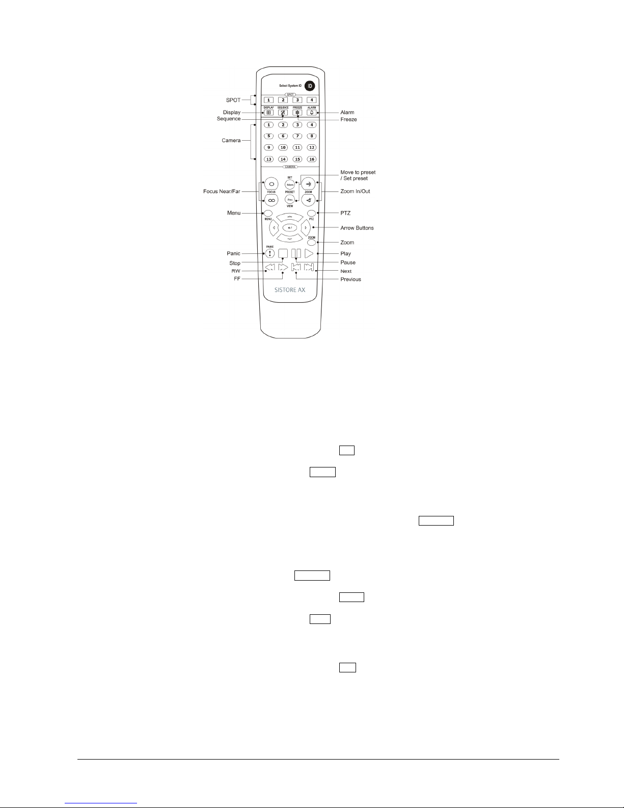
Fire Safety & Security Products 03.2007
Fig. 20 Infrared remote control
Power LED The Power LED is lit when the unit is On.
Network LED The Network LED flickers when the unit is connected to a network via either
Ethernet or modem.
HDD LED The HDD LED flickers when the DVR is recording or searching video on the
hard disk drive.
Camera buttons
(1 to 16)
Pressing the individual camera buttons will cause the selected camera to
display full screen. Buttons 1 to 9 are also used to enter passwords.
PTZ button
Pressing the PTZ button enters the PTZ (Pan/Tilt/Zoom) mode which allows
you to control properly configured cameras.
Display button
The Display button has two functions. First, it toggles between different
display formats. The available formats are: 4x4, 3x3, 2x2 and PIP. Second,
pressing and holding the button for 5 seconds or longer will switch the video
output between Video Out (BNC or SVHS Out) and VGA Out. The button is
also used for Zoom In while in the PTZ mode.
Sequence button
When in the live mode, pressing the Sequence button displays another full
live channel sequentially. When in one of the multi-view formats, pressing
this button will cause the DVR to sequence cameras in two sequence
modes: “Page” and “Cameo”. In the Page mode, the DVR sequences
through user-defined screen layouts (pages). In the Cameo mode, the
bottom, right screen to display live cameras sequentially. Pressing the
Sequence button while in the Sequence mode will exit the Sequence mode.
The button is also used for Zoom Out while in the PTZ mode.
Freeze button
Pressing the Freeze button freezes the current live screen. The button is
also used for Near Focus in the PTZ mode.
Alarm button
The Alarm button has two functions. First, it will reset the DVR’s outputs
including the internal buzzer during an alarm. Second, it will display the
event log when you are in the live monitoring mode unless there is an active
alarm. This operation can be user password protected. The button is also
used for Far Focus while in the PTZ mode.
Spot button
Pressing the Spot button allows you to select which cameras will display on
the four Spot Monitors. After selecting the monitor you can opt to have that
Spot Monitor display a single camera or all cameras sequentially. The
infrared remote control allows you to go directly to the individual Spot
Monitor menus. The button is also saves Presets in PTZ mode.

Configuration
30
Siemens Building Technologies
Fire Safety & Security Products 03.2007
Menu button
Pressing the Menu button enters the Setup screen. You will need to enter
the authorized user and password to access Setup. Pressing the button
also closes the current menu or setup dialog box. In the Playback mode,
pressing the Menu button displays the Search menu. In Search mode clipcopying can be done instantly by pressing and holding the button for two or
more seconds. The button is also loads a Preset View in the PTZ mode.
Search button
Pressing the Search
button enters the Search menu. Pressing the button
again exits the Search mode. You will need to log into the system as a
qualified user to enter the Search mode from the Live Monitoring mode.
RW (Rewind) button
Pressing the RW button plays video backward at high speed. Pressing the
button again toggles the playback speed from , and . The
screen displays
, and respectively.
Previous button
Pressing the Previous button goes to the previous image.
Play/Pause button
Pressing the Play/Pause button plays back images at regular speed.
Pressing the button while in the Playback mode pauses the video. The
screen displays
when the DVR is playing back video. The screen displays
when in the Pause mode.
Next button
Pressing the Next button goes to the next image.
FF (Fast Forward)
button
Pressing the FF button plays video forward at high speed. Pressing the
button again toggles the playback speed from , and . The
screen displays
, and respectively.
Zoom button
Pressing the Zoom button zooms the current image on the screen. A PIP
with a rectangle temporarily displays showing what area of the screen has
been enlarged. You can use the arrow buttons to move the rectangle to
another area. Pressing the
(Enter) button toggles the zoom size
between 2x, 3x and 4x.
Enter button
The
(Enter) button selects a highlighted item or completes an entry that
you have made during system setup.
Up, Down, Left, Right
Arrow buttons
These buttons are used to navigate through menus and GUI. You can also
use them to change numbers by highlighting a number in the menu and
using the Up and Down arrow buttons to increase or decrease the number’s
value.
The arrow buttons are also used to control Pan and Tilt when in the PTZ
mode. When in the PIP display format, pressing the Up and Down arrow
buttons moves the position of the small screen counter-clockwise and
clockwise, and pressing the Left and Right buttons moves through screen
pages.
Panic button
Pressing the Panic button starts panic recoding of all camera channels, and
displays on the screen. Pressing the button again will stop panic
recording.
ID button on remote
control
If a DVR System ID is set to 0, the infrared remote control will control that
DVR without any additional operations. (Refer to Section 8.11.1: Information
screen for further information on setting the System ID.) If the system ID is 1
to 16, you must to press the ID button on the remote control and then press
the number button (1 to 16) in order to control that DVR. If the System ID of
two or more DVRs is set to 0, those DVRs will react to the infrared remote
control at the same time.
 Loading...