

Siemens SISTORE AX9, SISTORE AX16 User Manual
CCTV
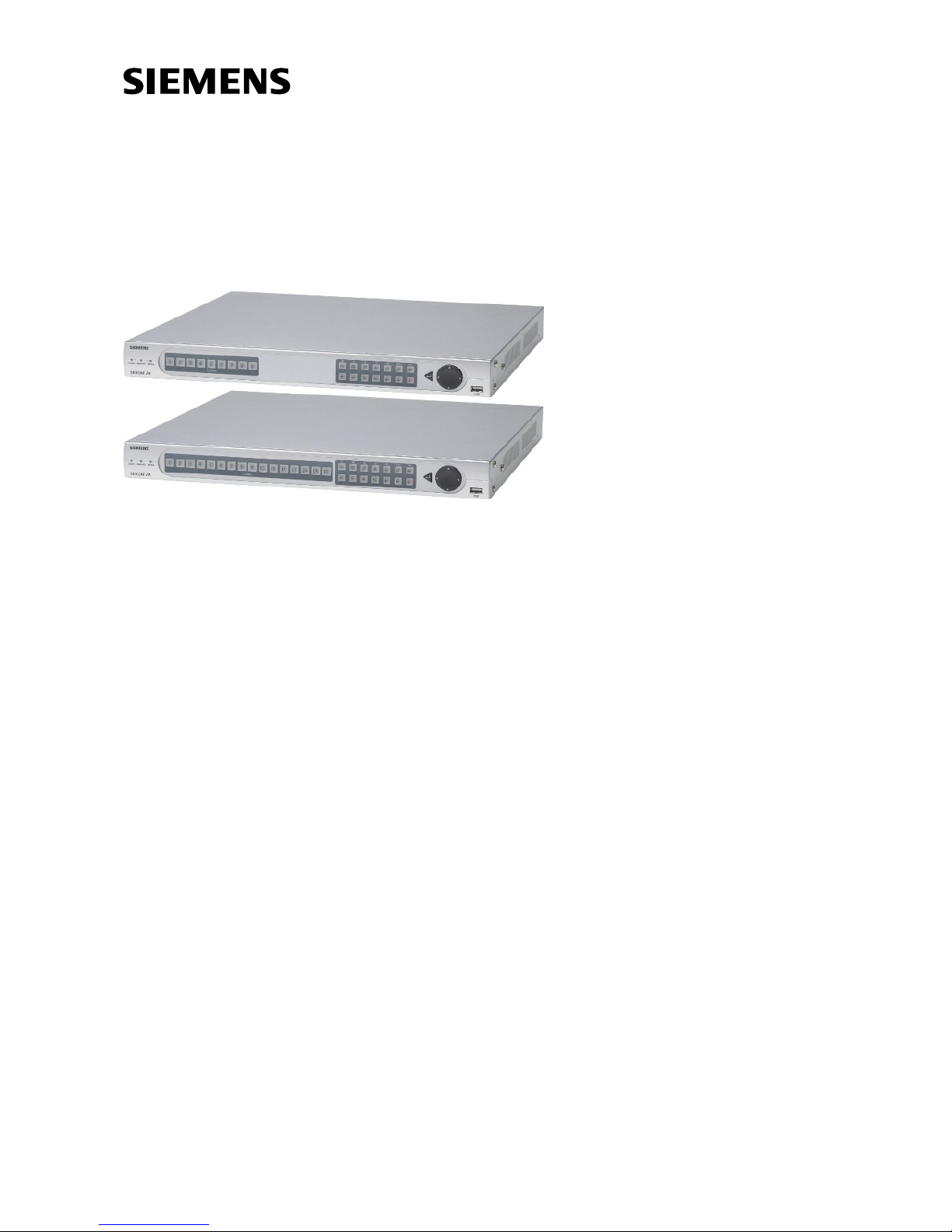
SISTORE AX9/AX16 (V2.5)
User’s Manual
Fire & Security Products
Siemens Building Technologies

Liefermöglichkeiten und technische Änderungen vorbehalten.
Data and design subject to change without notice. / Supply subject to availability.
© 2004 Copyright by
Siemens Building Technologies AG
Wir behalten uns alle Rechte an diesem Dokument und an dem in ihm dargestellten Gegenstand vor. Der Empfänger anerkennt diese
Rechte und wird dieses Dokument nicht ohne unsere vorgängige schriftliche Ermächtigung ganz oder teilweise Dritten zugänglich machen
oder außerhalb des Zweckes verwenden, zu dem es ihm übergeben worden ist.
We reserve all rights in this document and in the subject thereof. By acceptance of the document the recipient acknowledges these rights
and undertakes not to publish the document nor the subject thereof in full or in part, nor to make them available to any third party without our
prior express written authorization, nor to use it for any purpose other than for which it was delivered to him.

Contents
Preface......................................................................................................................7
Compliance notice of FCC ........................................................................................7
Important Safeguards................................................................................................8
1 Introduction...........................................................................................11
1.1 Features..................................................................................................11
1.2 Technical Overview.................................................................................12
2 Installation.............................................................................................13
2.1 Package Contents...................................................................................13
2.2 Required Installation Tools .....................................................................13
2.3 Setting Unit for PAL or NTSC .................................................................13
2.4 Connecting the Video Source.................................................................14
2.5 Connecting the Loop Through Video......................................................14
2.6 Connecting the Monitor...........................................................................14
2.7 Connecting Audio....................................................................................15
2.8 Connecting Alarms..................................................................................15
2.8.1 AI 1 to 16 (Alarm In)................................................................................16
2.8.2 GND (Ground).........................................................................................16
2.8.3 AO 1 and 4 (Alarm Out)..........................................................................16
2.8.4 ARI (Alarm Reset In)...............................................................................16
2.9 Connecting to the RS485........................................................................17
2.10 Connecting to the RS232 Port................................................................17
2.11 Connecting to the UltraWide SCSI Port..................................................18
2.12 Connecting to the Network Port..............................................................18
2.13 Connecting to the USB Port....................................................................19
2.14 Factory Reset..........................................................................................19
2.15 Connecting the Power Cord....................................................................20
3 Configuration.........................................................................................21
3.1 Front Panel Controls...............................................................................21
3.1.1 Power LED..............................................................................................21
3.1.2 Network LED...........................................................................................21
3.1.3 Backup LED............................................................................................21
3.1.4 Camera Buttons (1 to 16)........................................................................21
3.1.5 Sequence Button.....................................................................................22
3.1.6 Display Button.........................................................................................22
3.1.7 PTZ Button..............................................................................................22
3.1.8 Freeze Button..........................................................................................22
3.1.9 Alarm Button ...........................................................................................22
3.1.10 Spot Button .............................................................................................22
3.1.11 Menu Button............................................................................................22
3.1.12 RW (Rewind) Button ...............................................................................23
3.1.13 PREV (Previous) Button .........................................................................23
3.1.14 Search/Stop Button.................................................................................23
3.1.15 PLAY/PAUSE Button ..............................................................................23
3.1.16 Next Button .............................................................................................23
3.1.17 FF (Fast Forward) Button........................................................................23
3.1.18 REC (Record) Button..............................................................................23
3.1.19 Enter Button............................................................................................24
3.1.20 Up, Down, Left, Right Arrow Buttons......................................................24
3
Siemens Building Technologies SISTORE AX9 AX16_EN.doc
Fire & Security Products 09.2004

3.2 Turning on the Power..............................................................................24
3.3 Initial Unit Setup......................................................................................24
3.4 Quick Setup Screen................................................................................25
3.5 Normal Setup Screen..............................................................................26
3.5.1 System Information.................................................................................26
3.5.2 Date/Time Setup.....................................................................................29
3.5.3 System Check Screen.............................................................................32
3.5.4 Storage Screen.......................................................................................33
3.5.5 System Log Screen.................................................................................35
3.5.6 System Shutdown...................................................................................35
3.6 Configuring Input Devices.......................................................................36
3.6.1 Camera Setup Screen.............................................................................36
3.6.2 Alarm In Setup Screen............................................................................37
3.6.3 Motion Detector.......................................................................................38
3.6.4 Alarm Out Setup Screen.........................................................................40
3.6.5 Audio Setup Screen................................................................................41
3.6.6 RS232/RS485 Setup Screen..................................................................42
3.7 Configuring Recording Settings..............................................................43
3.7.1 Record Mode Setup Screen....................................................................43
3.7.2 Time-Lapse Record Mode Setup Screen................................................44
3.7.3 Time-Lapse Recording Schedule............................................................45
3.7.4 Pre-Event Recording Setup Screen........................................................46
3.8 Event Action Setup..................................................................................47
3.8.1 Alarm In Event Action (Record) Setup Screen........................................47
3.8.2 Alarm In Event Action (Alarm Out) Setup Screen...................................48
3.8.3 Alarm In Event Action (Notify) Setup Screen..........................................49
3.8.4 Motion Detector Event Action (Record) Setup Screen ...........................49
3.8.5 Motion Detector Event Action (Alarm Out) Setup Screen.......................50
3.8.6 Motion Detector Event Action (Notify) Setup Screen..............................51
3.8.7 Video Loss Event Action (Record) Setup Screen...................................51
3.8.8 Video Loss Event Action (Alarm Out) Setup Screen ..............................52
3.8.9 Video Loss Event Action (Notify) Setup Screen......................................53
3.9 Display Setup..........................................................................................54
3.9.1 OSD (On-Screen Display) Setup Screen................................................54
3.9.2 Main Monitoring Setup Screen................................................................55
3.9.3 Spot Monitoring Setup Screen................................................................56
3.10 Network Setup Screen............................................................................57
3.10.1 LAN Setup Screen ..................................................................................58
3.10.2 Modem Setup..........................................................................................59
3.10.3 Callback Center (LAN) Setup Screen.....................................................60
3.10.4 Callback Center (Modem) Setup Screen................................................61
3.11 Password Setup Screen..........................................................................62
3.12 Config Screen .........................................................................................63
3.12.1 Archive ....................................................................................................64
3.12.2 Clip Copy.................................................................................................66
3.12.3 Load Default Setup .................................................................................68
3.12.4 Clear All Data..........................................................................................68
4 Operation ...............................................................................................69
4.1 Turning on the Power..............................................................................69
4.2 Live Monitoring........................................................................................69
4.2.1 Active Cameo Mode................................................................................70
4.2.2 PIP Mode.................................................................................................70
4.2.3 PTZ Mode................................................................................................70
4
Siemens Building Technologies SISTORE AX9 AX16_EN.doc
Fire & Security Products 06.2004

4.3 Recording Video......................................................................................71
4.4 Recording Audio......................................................................................71
4.5 Playing Recorded Video .........................................................................72
4.5.1 Camera Buttons (1 to 16)........................................................................72
4.5.2 Display Button.........................................................................................72
4.5.3 RW (Rewind) Button ...............................................................................72
4.5.4 PREV (Previous) Button .........................................................................72
4.5.5 Stop Button .............................................................................................72
4.5.6 Next Button .............................................................................................72
4.5.7 FF (Fast Forward) Button........................................................................73
4.6 Searching Video......................................................................................73
4.6.1 Change Data Source ..............................................................................73
4.6.2 Date/Time Search...................................................................................74
4.6.3 Calendar Search.....................................................................................74
4.6.4 Event Search...........................................................................................75
5 Appendix A — USB-IDE Hard Disk Drive Preparation.......................78
5.1 Preparing the USB-IDE hard disk drive in Windows 2000......................78
5.2 Preparing the USB-IDE hard disk drive in Windows 98..........................79
6 Appendix B — Reviewing Video Clips................................................80
7 Appendix C — Troubleshooting..........................................................82
8 Appendix D — Connector Pin Outs.....................................................83
8.1 Alarm I/O Connector and RS485 Connector Pin Outs............................83
9 Appendix E — Connection Diagram...................................................84
9.1 Sample I. Connecting the Dome Camera and SISTORE AX9/AX16 ....84
9.2 Sample II. Connecting the External Modem and SISTORE AX RAS....84
9.3 Sample III. Connecting the SISTORE AX and SCU...............................85
10 Appendix F — Recording Table...........................................................86
10.1 All 16 Channel Recording Times with 250 GB HDD (Days)...................86
11 Appendix G — Screens Map................................................................87
12 Appendix H — Specifications..............................................................88
13 Keyword Index.......................................................................................90
5
Siemens Building Technologies SISTORE AX9 AX16_EN.doc
Fire & Security Products 09.2004

Preface
Preface
Compliance notice of FCC
This equipment has been tested and found to comply with the limits for a CLASS A
Digital Device, pursuant to part 15 of the FCC rules. These limits are designed to
provide reasonable protection against harmful interference when the equipment is
operated in a commercial environment. This equipment generates, uses, and can
radiate frequency energy and if not installed and used in accordance with the
instruction manual, may cause harmful interference to radio communications.
Operation of this equipment in a residential area is likely to cause harmful
interference, in which case users will be required to correct the interference at their
own expense.
WARNING
Changes or modifications not expressly approved by the party responsible for
compliance could void the user’s authority to operate the equipment. This class
of digital apparatus meets all requirements of the Canadian Interferencecausing Equipment Regulations.
The information in this manual is believed to be accurate as of the date of
publication. Siemens is not responsible for any problems resulting from the use
thereof. The information contained herein is subject to change without notice.
Revisions or new editions to this publication may be issued to incorporate such
changes.
7
Siemens Building Technologies SISTORE AX9 AX16_EN.doc
Fire & Security Products 09.2004

Preface
Important Safeguards
WARNING
TO REDUCE THE RISK OF ELECTRIC SHOCK, DO NOT REMOVE COVER
(OR BACK). NO USER-SERVICEABLE PARTS INSIDE. REFER SERVICING
TO QUALIFIED SERVICE PERSONNEL.
z Read Instructions
All the safety and operating instructions should be read before the appliance is
operated.
z Retain Instructions
The safety and operating instructions should be retained for future reference.
z Cleaning
Unplug this equipment from the wall outlet before cleaning it. Do not use liquid
aerosol cleaners. Use a damp soft cloth for cleaning.
z Attachments
Never add any attachments and/or equipment without the approval of the
manufacturer as such additions may result in the risk of fire, electric shock or
other personal injury.
z Water and/or Moisture
Do not use this equipment near water or in contact with water.
z Accessories
z Do not place this equipment on an unstable cart, stand or table. The equipment
may fall, causing serious injury to a child or adult, and serious damage to the
equipment. Wall or shelf mounting should follow the manufacturer's instructions,
and should use a mounting kit approved by the manufacturer.
z This equipment and cart combination should be moved with care. Quick stops,
excessive force, and uneven surfaces may cause the equipment and cart
combination to overturn.
z Power Sources
This equipment should be operated only from the type of power source indicated
on the marking label. If you are not sure of the type of power, please consult
your equipment dealer or local power company.
z Power Cords
Operator or installer must remove power and TNT connections before handling
the equipment.
z Lightning
For added protection for this equipment during a lightning storm, or when it is left
unattended and unused for long periods of time, unplug it from the wall outlet
and disconnect the antenna or cable system. This will prevent damage to the
equipment due to lightning and power-line surges.
z Overloading
Do not overload wall outlets and extension cords as this can result in the risk of
fire or electric shock.
z Objects and Liquids
Never push objects of any kind through openings of this equipment as they may
touch dangerous voltage points or short out parts that could result in a fire or
electric shock. Never spill liquid of any kind on the equipment.
8
Siemens Building Technologies SISTORE AX9 AX16_EN.doc
Fire & Security Products 09.2004

Preface
z Servicing
Do not attempt to service this equipment yourself. Refer all servicing to qualified
service personnel.
z Damage requiring Service
Unplug this equipment from the wall outlet and refer servicing to qualified service
personnel under the following conditions:
– When the power-supply cord or the plug has been damaged.
– If liquid is spilled, or objects have fallen into the equipment.
– If the equipment has been exposed to rain or water.
– If the equipment does not operate normally by following the operating
instructions, adjust only those controls that are covered by the operating
instructions as an improper adjustment of other controls may result in damage
and will often require extensive work by a qualified technician to restore the
equipment to its normal operation.
– If the equipment has been dropped, or the cabinet damaged.
– When the equipment exhibits a distinct change in performance — this
indicates a need for service.
z Replacement Parts
When replacement parts are required, be sure the service technician has used
replacement parts specified by the manufacturer or that have the same
characteristics as the original part. Unauthorized substitutions may result in fire,
electric shock or other hazards.
z Safety Check
Upon completion of any service or repairs to this equipment, ask the service
technician to perform safety checks to determine that the equipment is in proper
operating condition.
z Field Installation
This installation should be made by a qualified service person and should
conform to all local codes.
z Correct Batteries
Warning: Risk of explosion if battery is replaced by an incorrect type. Dispose of
used batteries according to the instructions.
z Tmra
A manufacturer’s maximum recommended ambient temperature (Tmra) for the
equipment must be specified so that the customer and installer may determine a
suitable maximum operating environment for the equipment.
z Elevated Operating Ambient Temperature
If installed in a closed or multi-unit rack assembly, the operating ambient
temperature of the rack environment may be greater than room ambient.
Therefore, consideration should be given to installing the equipment in an
environment compatible with the manufacturer’s maximum rated ambient
temperature (Tmra).
z Reduced Air Flow
Installation of the equipment in the rack should be such that the amount of
airflow required for safe operation of the equipment is not compromised.
z Mechanical Loading
Mounting of the equipment in the rack should be such that a hazardous
condition is not caused by uneven mechanical loading.
9
Siemens Building Technologies SISTORE AX9 AX16_EN.doc
Fire & Security Products 09.2004

Preface
z Circuit Overloading
Consideration should be given to connection of the equipment to supply circuit
and the effect that overloading of circuits might have on over current protection
and supply wiring. Appropriate consideration of equipment nameplate ratings
should be used when addressing this concern.
z Reliable Earthing (Grounding)
Reliable grounding of rack mounted equipment should be maintained. Particular
attention should be given to supply connections other than direct connections to
the branch circuit (e.g., use of power strips).
z Cable lengths
For reasons of EMC the cable used for RS232, audio In / Out, SCSI
connections and power supply must be not any longer than 3 meters.
10
Siemens Building Technologies SISTORE AX9 AX16_EN.doc
Fire & Security Products 09.2004
Introduction
1 Introduction
1.1 Features
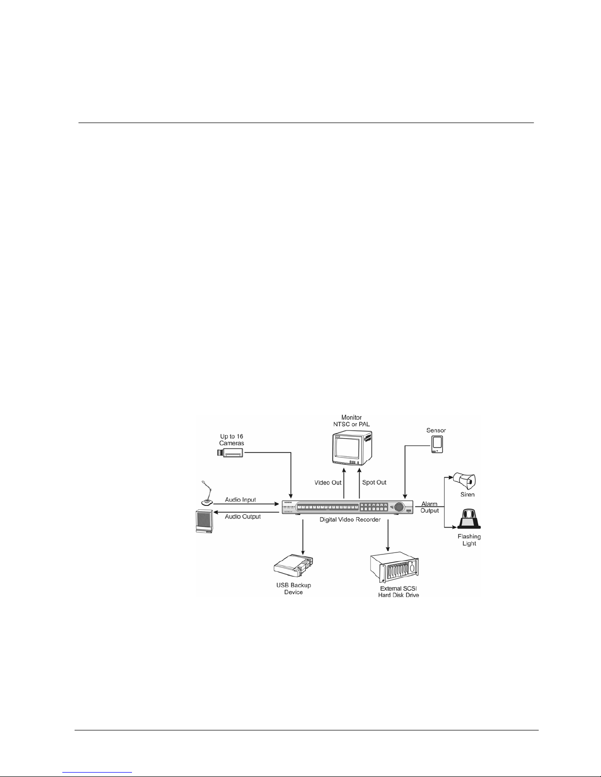
Your color digital video recorder (DVR) provides recording capabilities for 9 or 16
camera inputs. It provides exceptional picture quality in both live and playback
modes, and offers the following features:
z Efficient video compression through “MPEG4 Technology“
z 9 or 16 Composite Input Connectors
z Compatible with Color (PAL or NTSC) and B&W (CCIR and EIA-170) Video
Sources
z Multiple Search Functions (Date/Time, Calendar, Event)
z Records up to 50 PAL Images per Second (60 NTSC Images per Second)
z “Loop-Through” Video Connectors
z Continuous Recording in Disk Overwrite Mode
z Video Archiving via Ultra SCSI Interface
z Continues Recording while Archiving, Transmitting to Remote Site and during
Playback
z User-friendly Graphical User Interface (GUI) Menu System in Multiple
Languages
z Two Record Modes (Time and Event)
z Audio Recording and Playback
z Alarm Connections Include: Input, Output and Reset Input
z Built-in Alarm Buzzer
z Live or Recorded Video Access via Ethernet or External Modem
z
Fig. 1 Typical DVR installation.
11
Siemens Building Technologies SISTORE AX9 AX16_EN.doc
Fire & Security Products 09.2004

Introduction
1.2 Technical Overview
Your DVR can replace both a time-lapse VCR and a multiplexer in a security
installation. However, it has many features that make it much more powerful and
easier to use than even the most advanced VCR.
The DVR converts analog PAL or NTSC video to digital images and records them
on a hard disk drive. Using a hard disk drive allows you to access recorded video
almost instantaneously; there is no need to rewind tape. The technology also
allows you to view recorded video while the DVR continues recording video.
Digitally recorded video has several advantages over analog video recorded on
tape. There is no need to adjust tracking. You can freeze frames, fast forward,
fast reverse, slow forward and slow reverse without image streaking or tearing.
Digital video can be indexed by time or events, and you can instantly view video
after selecting the time or event.
Your DVR can be set up for event or time-lapse recording. You can define times to
record, and the schedule can change for different days of the week and user
defined holidays.
The DVR can be set up to alert you when the hard disk drive is full, or it can be set
up to record over the oldest video once the disk is full.
Your DVR uses a proprietary encryption scheme making it nearly impossible to
alter video.
You can view video and control your DVR remotely by connecting via modem or
Ethernet. There is a SCSI port that can be used to record or archive video to
external hard disk drives, and also there are two USB ports that can be used to
upgrade the system or copy video clips to external hard disk drives, CD-RW drives
or flash drives.
NOTE:
This manual covers the 9- and 16-channel digital video recorders.
The DVRs are identical except for the number of cameras and alarms that can be
connected and the number of cameras that can be displayed.
For simplicity, the illustrations and descriptions in this manual refer to the 16-
camera model.
12
Siemens Building Technologies SISTORE AX9 AX16_EN.doc
Fire & Security Products 09.2004
Installation
2 Installation
2.1 Package Contents
The package contains the following:
z Digital video recorder
z Adaptor (including power cord)
z Alarm I/O board
z Multilingual user’s manual, multilingual RAS software and user’s manual on CD-
ROM
z CD-ROM
z Multilingual quick reference guide
z 19 inch bracket
2.2 Required Installation Tools
No special tools are required to install the DVR. Refer to the installation manuals
for the other items that make up part of your system.
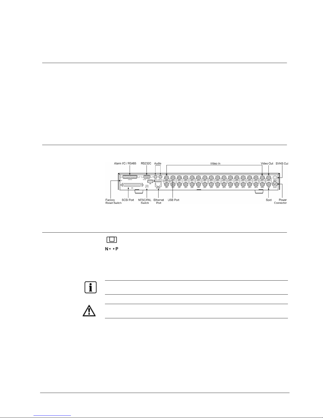
Fig. 2 16-Channel DVR rear panel.
2.3 Setting Unit for PAL or NTSC
Fig. 3 PAL / NTSC switch.
Your DVR can be used with either PAL or NTSC equipment. Before turning on the
DVR, set the switch to P (PAL) or N (NTSC) to match your equipment.
NOTE:
You cannot mix PAL and NTSC equipment. For example you cannot use a PAL camera and an
NTSC monitor.
CAUTION
If you set the switch from PAL (NTSC) to NTSC (PAL), please do the Factory
Reset and Clear All Data. If not, it causes the DVR to perform wrong
operations.
13
Siemens Building Technologies SISTORE AX9 AX16_EN.doc
Fire & Security Products 09.2004
Installation
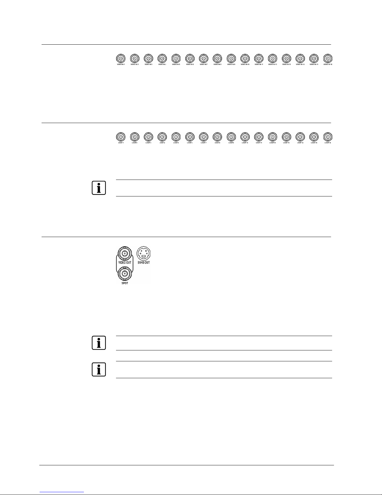
2.4 Connecting the Video Source
Fig. 4 Video input connectors.
Connect the coaxial cables from the video sources to the BNC Video In
connectors.
2.5 Connecting the Loop Through Video
Fig. 5 Video Loop Through connectors.
If you would like to connect your video source to another device, you can use the
Loop BNC connectors.
NOTE:
The Loop BNC connectors are auto terminated. Do NOT connect a cable to the Loop BNC unless it is
connected to another terminated device because it will cause poor quality video.
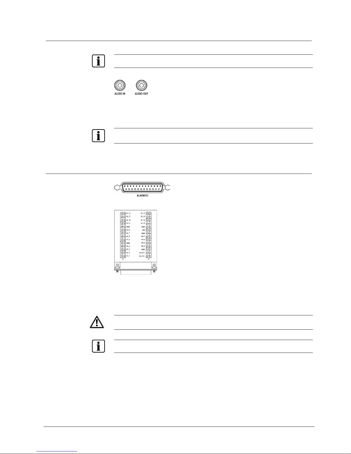
2.6 Connecting the Monitor
Fig. 6 Video Out connectors.
Connect the monitor to either the Video Out or SVHS Out connector.
Connect the spot monitor to the SPOT connector if required.
NOTE:
If your monitor has an SVHS input, use it for better quality video display.
NOTE:
The Video Out (BNC) and the SVHS Out connectors may be connected to individual monitors for
simultaneous operation.
14
Siemens Building Technologies SISTORE AX9 AX16_EN.doc
Fire & Security Products 09.2004
Installation
2.7 Connecting Audio
NOTE:
It is the user’s responsibility to determine if local laws and regulations permit recording audio.
Fig. 7 Audio In and Out connectors.
Your DVR can record audio. Connect the audio source to Audio In. Connect
Audio Out to your amplifier.
NOTE:
The DVR does not have amplified audio output, so you will need a speaker with an amplifier. The
audio input can be from an amplified source or directly from a microphone.
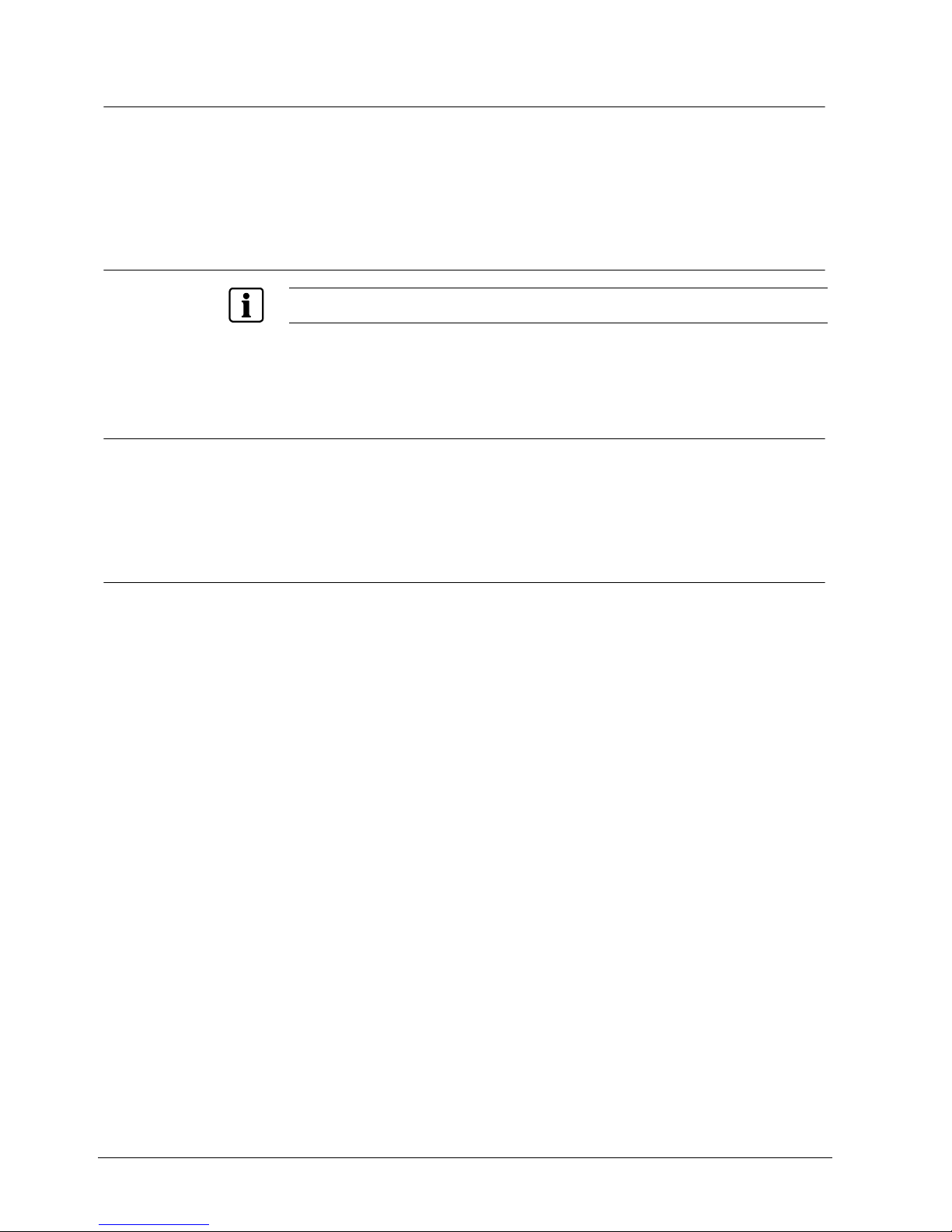
2.8 Connecting Alarms
Fig. 8 Alarm Input/Output and RS485 connector
Fig. 9 Alarm Input/Output board and alarm connector strips
An Alarm I/O port (DB-25 male connector) is provided to connect the alarm inputs
and alarm outputs. Connect the wires to connectors on the Alarm I/O board
(supplied with the unit), and then connect the board to the Alarm I/O port.
CAUTION Do not attempt to wire directly to the DB-25 male connector.
NOTE:
The Alarm I/O Board consists of alarm connector strips and RS485 connector.
15
Siemens Building Technologies SISTORE AX9 AX16_EN.doc
Fire & Security Products 09.2004
Installation
2.8.1 AI 1 to 16 (Alarm In)
You can use external devices to signal the DVR to react to events. Mechanical or
electrical switches can be wired to the AI (Alarm In) and GND (Ground)
connectors. The threshold voltage is 4.3V and should be stable at least 0.5
seconds to be detected. See Chapter 3 — Configuration for configuring alarm
input.
2.8.2 GND (Ground)
NOTE:
All the connectors marked GND are common.
Connect the ground side of the Alarm input and/or alarm output to the GND
connector.
2.8.3 AO 1 and 4 (Alarm Out)
The DVR can activate external devices such as buzzers or lights. Connect the
device to the AO (Alarm Out) and GND (Ground) connectors. AO is an active low
open collector output which sinks 5 mA 12 V and 30 mA 5V. See Chapter 3 —
Configuration for configuring alarm output.
2.8.4 ARI (Alarm Reset In)
An external signal to the Alarm Reset In can be used to reset both the Alarm Out
signal and the DVR’s internal buzzer. Mechanical or electrical switches can be
wired to the AI (Alarm In) and GND (Ground) connectors. The threshold voltage is
4.3 V and should be stable at least 0.5 seconds to be detected. Connect the wires
to the ARI (Alarm Reset In) and GND (Ground) connectors.
16
Siemens Building Technologies SISTORE AX9 AX16_EN.doc
Fire & Security Products 09.2004
Installation
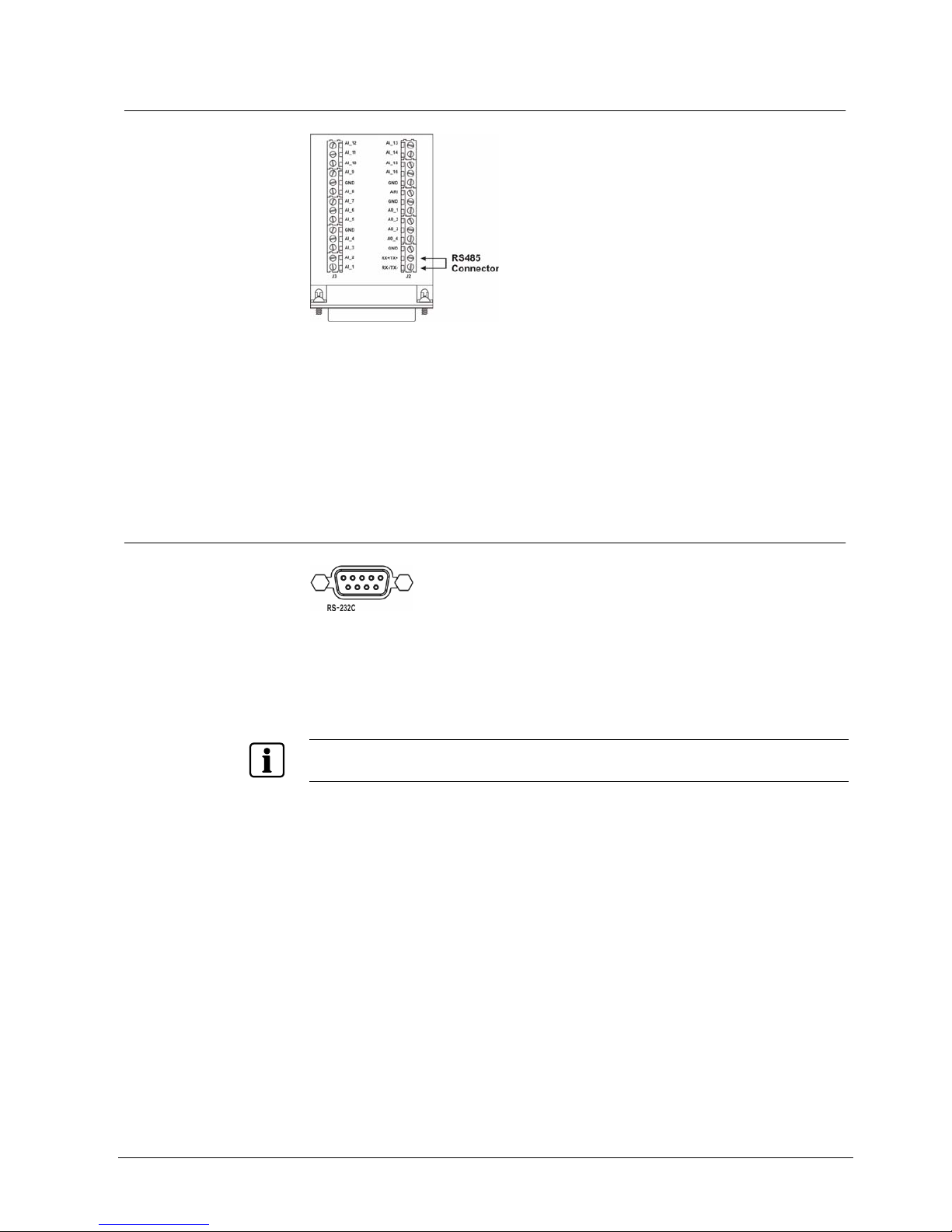
2.9 Connecting to the RS485
Fig. 10 RS485 connector
The DVR can be controlled remotely by an external device or control system, such
as a control keyboard, using RS485 half-duplex serial communications signals.
The RS485 connector can also be used to control PTZ (pan, tilt, zoom) cameras.
Connect RX+ and TX+ of the control system to the RX+/TX+ of the DVR, and RXand TX- to the RX-/TX-. See Chapter 3 — Configuration and the PTZ camera
manufacture’s manual for configuring the RS485 connection.
2.10 Connecting to the RS232 Port
Fig. 11 RS232 connector
An RS232 port is provided to connect a remote control keyboard, or connect an
external modem for remote monitoring, configuration and software upgrades. Use
a modem cable with a DB-9 female connector to connect to the DVR.
See Chapter 3 — Configuration for configuring the modem.
NOTE:
The DVR is not supplied with a modem cable, and many modems are not supplied with cables. Make
certain you have the correct cable when purchasing the modem.
17
Siemens Building Technologies SISTORE AX9 AX16_EN.doc
Fire & Security Products 09.2004
Installation
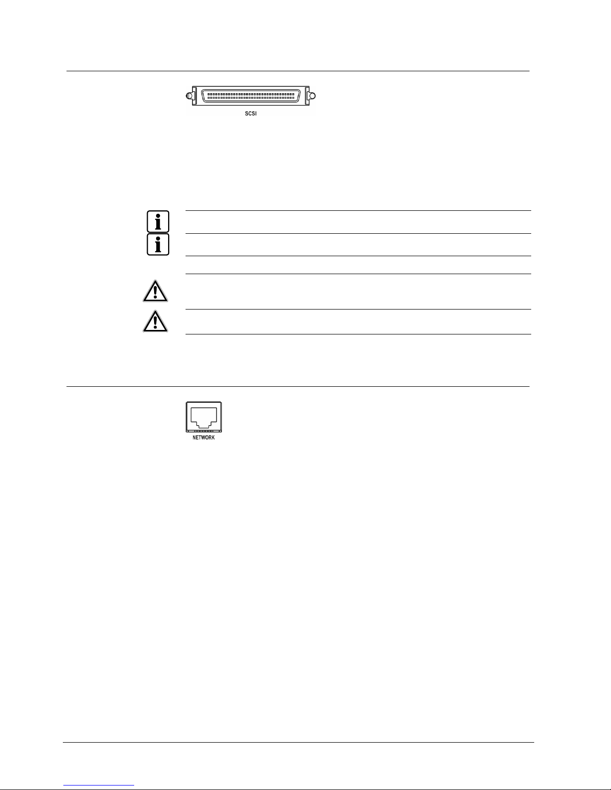
2.11 Connecting to the UltraWide SCSI Port
Fig. 12 SCSI connector
A SCSI port is provided to connect external storage devices for expanded storage.
Connect the external SCSI hard disk drive (RAID) cable to the high-density 68-pin
female UltraWide SCSI port. The length of SCSI cable should not exceed
1.5 meters. You can connect up to 15 UltraWide SCSI devices with SCSI IDs set
to 0, 1, 2, 3, 4, 5, 6, 8, 9, 10, 11, 12, 13, 14 and 15 respectively.
NOTE:
Do NOT set the SCSI ID to 7 because the ID number 7 was assigned to the Host.
NOTE:
The SCSI bus must be terminated properly, otherwise the DVR will not operate properly.
CAUTION
Do NOT connect the SCSI device while the DVR power is on. The DVR
must be powered down to connect the SCSI device and powered up again
after the SCSI device has been connected. Power up the SCSI device so it
is ready for operation in advance of powering up the DVR.
CAUTION
If the SCSI device is shut down while the device is operating, the DVR
system may not work normally.
2.12 Connecting to the Network Port
Fig. 13 Network connector.
The DVR can be networked using the 10/100 MB Ethernet connector. Connect a
Cat5 cable with an RJ-45 jack to the DVR connector. The DVR can be networked
for remote monitoring, searching, configuration and software upgrades. See
Chapter 3 — Configuration for configuring the Ethernet connections.
18
Siemens Building Technologies SISTORE AX9 AX16_EN.doc
Fire & Security Products 09.2004
Installation
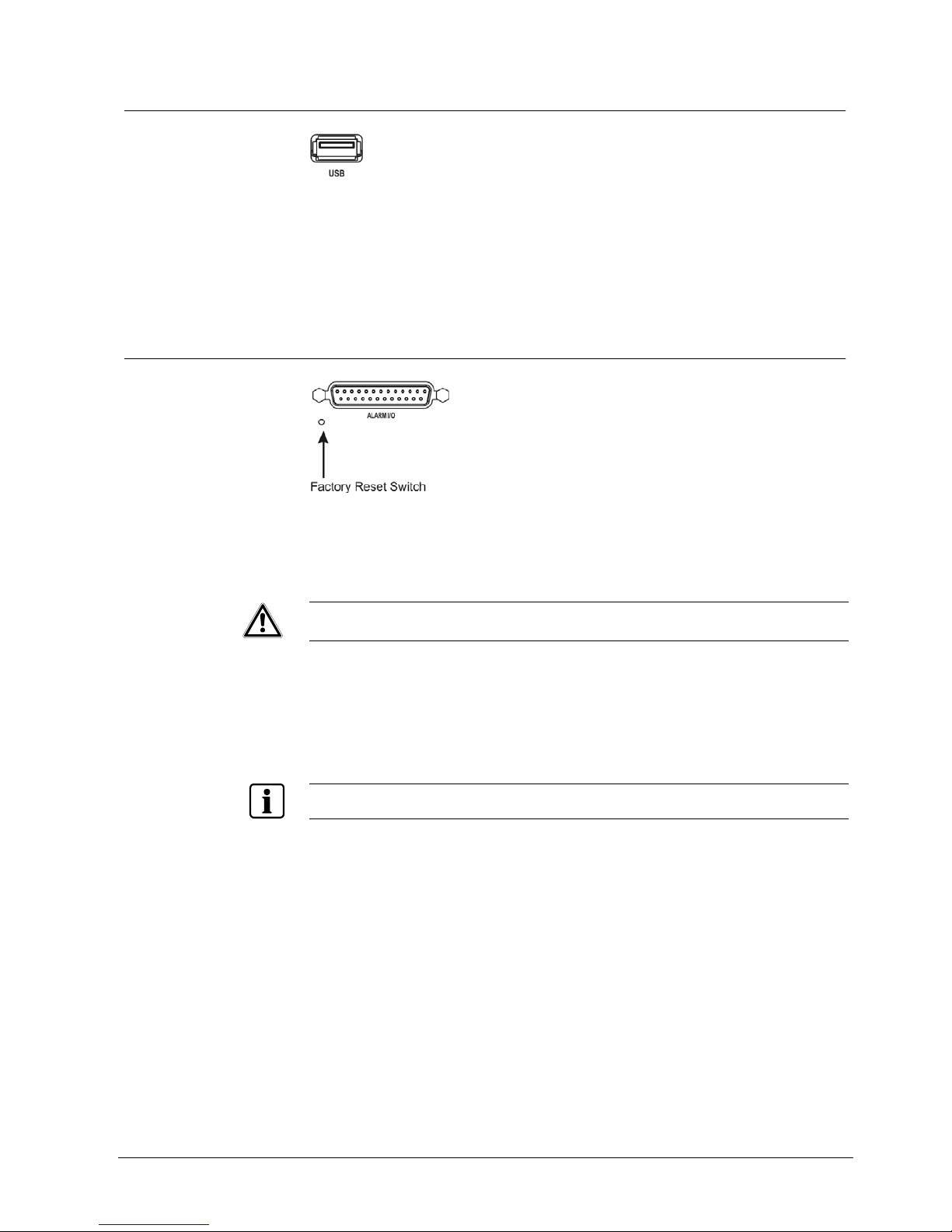
2.13 Connecting to the USB Port
Fig. 14 USB connector.
Two USB ports are provided to connect external hard disk drives, CD-RW or flash
drive for clip copy or system upgrade. Position the external drive close enough to
the DVR so that you can make the cable connections, usually less than 6 feet.
Use the USB cable provided with the drive to connect it to the DVR.
2.14 Factory Reset
Fig. 15 Factory reset switch.
The DVR has a Factory Reset switch to the right of the USB port. This switch will
only be used on the rare occasions that you want to return all the settings to the
original factory settings.
CAUTION When using the Factory Reset, you will lose any setting you have made.
To reset the unit, you will need a straightened paperclip:
1. Unplug the power to turn the DVR off.
2. Plug the power to turn it on again.
3. While the DVR is initializing, poke the straightened paperclip in the unlabeled
hole above the PAL / NTSC switch.
4. Hold the switch until all the LEDs on the front panel a re lit.
NOTE:
When the DVR successfully resets to factory defaults all the LEDs on the front panel flash three times.
5. Release the reset switch. All of the DVR’s settings are now at the original
settings it had when it left the factory.
19
Siemens Building Technologies SISTORE AX9 AX16_EN.doc
Fire & Security Products 09.2004
Installation
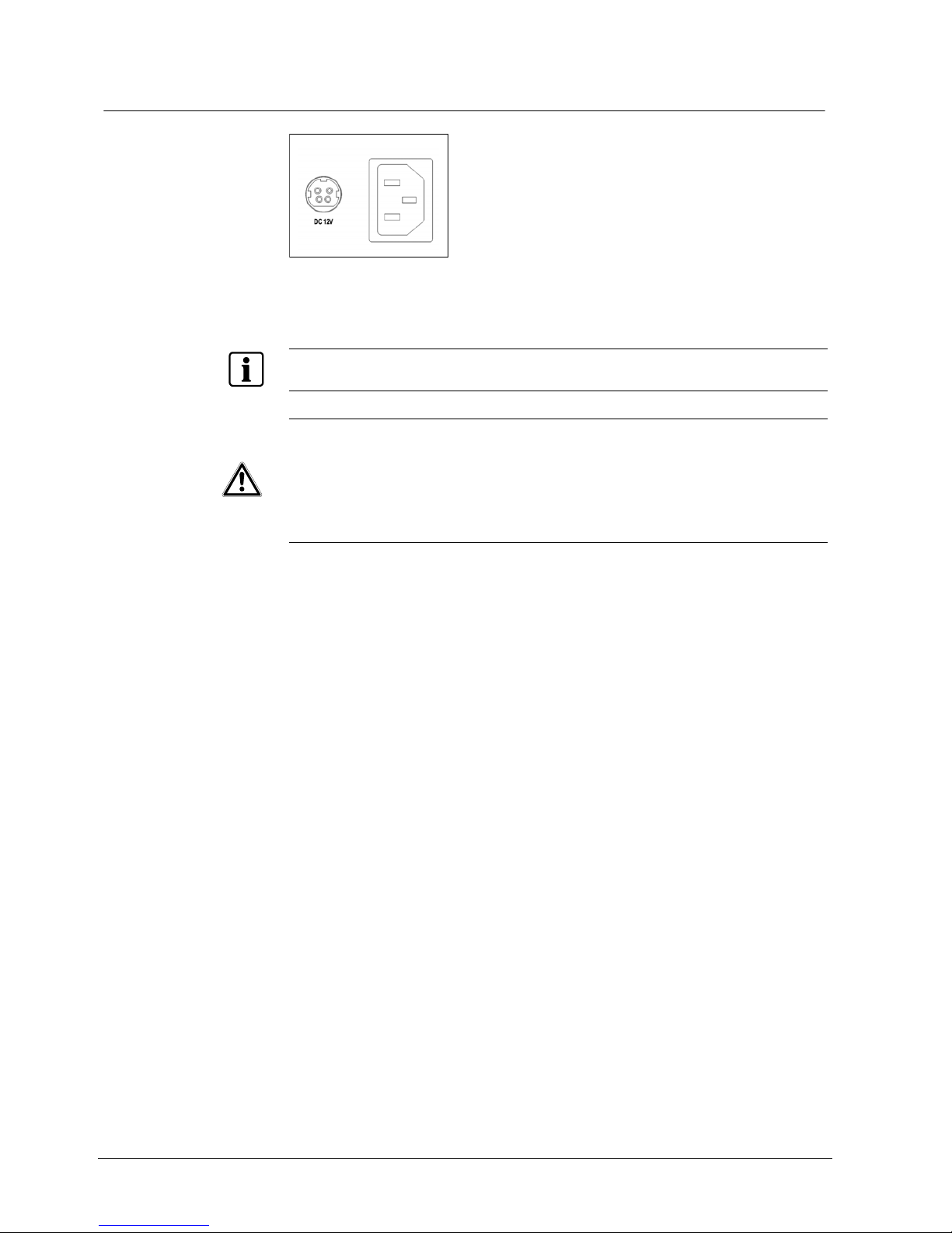
2.15 Connecting the Power Cord
Fig. 16 Power cord connector.
Connect the DC power cord of the adaptor to the DVR, and connect the AC power
cord to the adaptor and then to the wall outlet.
NOTE:
The power cord connector locks into position to prevent accidental power loss. Be sure to slide the
release away from the socket before removing the plug.
WARNING
ROUTE POWER CORDS SO THAT THEY ARE NOT A TRIPPING HAZARD.
MAKE CERTAIN THE POWER CORD WILL NOT BE PINCHED OR ABRADED
BY FURNITURE. DO NOT INSTALL POWER CORDS UNDER RUGS OR
CARPET.
THE POWER CORD HAS A GROUNDING PIN. IF YOUR POWER OUTLET
DOES NOT HAVE A GROUNDING PIN RECEPTACLE, DO NOT MODIFY THE
PLUG.
DO NOT OVERLOAD THE CIRCUIT BY PLUGGING TOO MANY DEVICES IN
TO ONE CIRCUIT.
Your DVR is now ready to operate.
Refer to Chapter 3 - Configuration and Chapter 4 - Operation.
20
Siemens Building Technologies SISTORE AX9 AX16_EN.doc
Fire & Security Products 09.2004
Configuration
3 Configuration
NOTE:
Your DVR should be completely installed before proceeding. Refer to Chapter 2 - Installation.
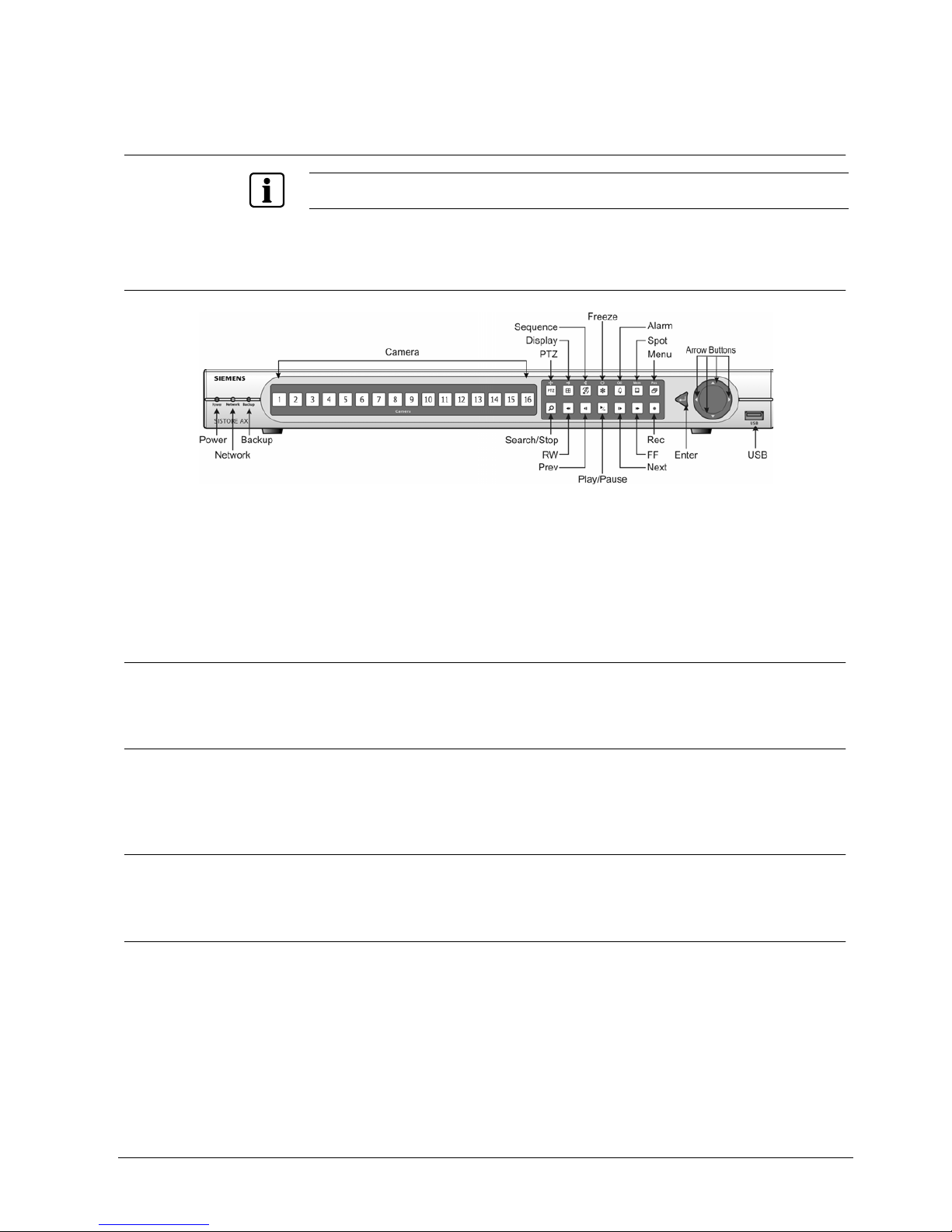
3.1 Front Panel Controls
Fig. 17 16-Channel DVR front panel.
The front panel looks and operates much like a VCR combined with a multiplexer.
Many of the buttons have multiple functions. The following describes each button
and control. Take a few minutes to review the descriptions. You will use these to
initially set up your DVR and for daily operations.
3.1.1 Power LED
The Power LED is lit when the DVR is on.
3.1.2 Network LED
The Network LED is lit when the unit is connected with RAS (Remote
Administration System) either via Ethernet or modem.
3.1.3 Backup LED
The Backup LED is lit when data is being backed up using the USB port.
3.1.4 Camera Buttons (1 to 16)
Pressing the individual camera buttons will cause the selected camera to display
full screen. They are also used to enter passwords.
21
Siemens Building Technologies SISTORE AX9 AX16_EN.doc
Fire & Security Products 09.2004

Configuration
3.1.5 Sequence Button
When in the live mode, pressing the Sequence button displays another full live
channel sequentially. When in one of the multi-view formats, pressing this button
will cause the DVR to sequence cameras in two sequence modes: “Page” and
“Cameo”. In the Page mode, the DVR sequences through user-defined screen
layouts (pages). In the Cameo mode, the bottom, right screen to display live
cameras sequentially. Pressing the Sequence button while in the Sequence mode
will exit the Sequence mode. Zooms Out in PTZ mode.
3.1.6 Display Button
Pressing the Display button toggles between different display formats. The
available formats are: full, 4 x 4, 3 x 3, 2 x 2 and PIP. Zooms In in PTZ mode.
3.1.7 PTZ Button
Pressing the PTZ button opens a Pan/Tilt/Zoom screen which allows you to control
properly configured cameras.
3.1.8 Freeze Button
Pressing the Freeze button freezes the current live screen. Used for near Focus in
the PTZ mode.
3.1.9 Alarm Button
The Alarm button has two functions. First, it will reset the DVR’s outputs including
the internal buzzer during an alarm. Second, it will display the event log when you
are in the live monitoring mode unless there is an active alarm. This operation can
be user password protected. Used for far Focus in PTZ mode.
3.1.10 Spot Button
Pressing the Spot button and pressing the individual camera buttons displays the
selected camera on the spot monitor. For the sequence display on the spot
monitor, press the Spot button and then Sequence button. Saves Presets in PTZ
mode.
3.1.11 Menu Button
Pressing the Menu button enters the Quick Setup screen. You will need to enter
the administrator password to access the Quick Setup. Pressing the button also
closes the current menu or setup dialog box. Pressing the MENU button displays
the Search menu while in the Playback mode. Pressing the button again closes
the Search menu. Loads a Preset View in PTZ mode.
22
Siemens Building Technologies SISTORE AX9 AX16_EN.doc
Fire & Security Products 09.2004
Configuration
3.1.12 RW (Rewind) Button
Pressing the RW button plays video backward at high speed. Pressing the button
again toggles the playback speed from , and . The screen displ ays
, and respectively.
Entering Fast Backward Playback mode from Live Monitoring mode can be
password protected.
3.1.13 PREV (Previous) Button
The PREV button only functions when playback video has been paused. Pressing
the PREV button plays video backward image-by-image.
3.1.14 Search/Stop Button
Pressing the Search/Stop button displays the Search menu. Pressing the button
again will exit the Search menu. This operation can be user password protected.
Pressing the Search/Stop button during Playback mode returns the DVR to the
Live Monitoring mode.
3.1.15 PLAY/PAUSE Button
Pressing the PLAY/PAUSE button plays back images at regular speed. Pressing
the button while in the playback mode will pause the video. The screen displays
when the DVR is playing back video. The screen displays
when in the Pause
mode.
Entering Playback mode from Live Monitoring mode can be user password
protected.
3.1.16 Next Button
The Next button only functions when playback video has been paused. Pressing
the Next button plays video forward image-by-image.
3.1.17 FF (Fast Forward) Button
Pressing the FF button plays video forward at high speed. Pressing the button
again toggles the playback speed from , and . The screen displays
, and respectively.
Entering Fast Playback mode from Live Monitoring mode can be password
protected.
3.1.18 REC (Record) Button
Press the REC button to set the DVR so that it is ready to record video, and
NOTHING will stop the recording, except an end of disk condition when the unit is
set to stop recording at the end of disk. A red dot appears on the screen when the
DVR is recording video. Press the button again to stop recording video. This
operation can be user password protected.
23
Siemens Building Technologies SISTORE AX9 AX16_EN.doc
Fire & Security Products 09.2004
Configuration
3.1.19 Enter Button
The (Enter) button selects a highlighted item or completes an entry that you
have made. It also sets or releases active cameo mode in the live or playback
modes.
3.1.20 Up, Down, Left, Right Arrow Buttons
These buttons are used to navigate through menus and Graphic User Interface
(GUI). They are also used to control Pan and Tilt when in the PTZ mode. The
arrow buttons can be used to move the position of the active cameo screen, and
also move through screen pages.
3.2 Turning on the Power
Connecting the power cord to the DVR turns on the unit. The unit will take
approximately 60 seconds to initialize.
3.3 Initial Unit Setup
Before using your DVR for the first time, you will want to establish the initial
settings. This includes items such as time and date, display language, camera,
audio, remote control, record mode, network and password. Your DVR can be set
up using various screens and dialog boxes.
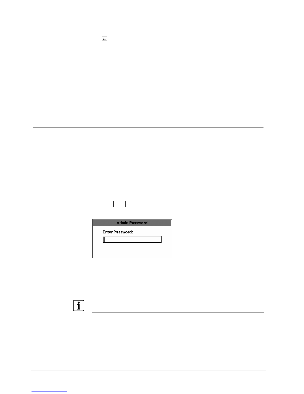
Press the Menu button to enter the setup screens. The Admin Password screen
appears.
Fig. 18 Admin Password screen.
Enter the password by pressing the appropriate combination of Camera number
buttons and then the Enter button. The factory default password is 4321. There
are two Setup screens: Quick Setup and Normal Setup. The factory default is the
Quick Setup screen.
NOTE:
The setup screens can also be accessed by entering the User password if the User password is
turned on. However, only access to the Clip Copy and Password setup screens is permitted.
24
Siemens Building Technologies SISTORE AX9 AX16_EN.doc
Fire & Security Products 09.2004
Configuration
3.4 Quick Setup Screen
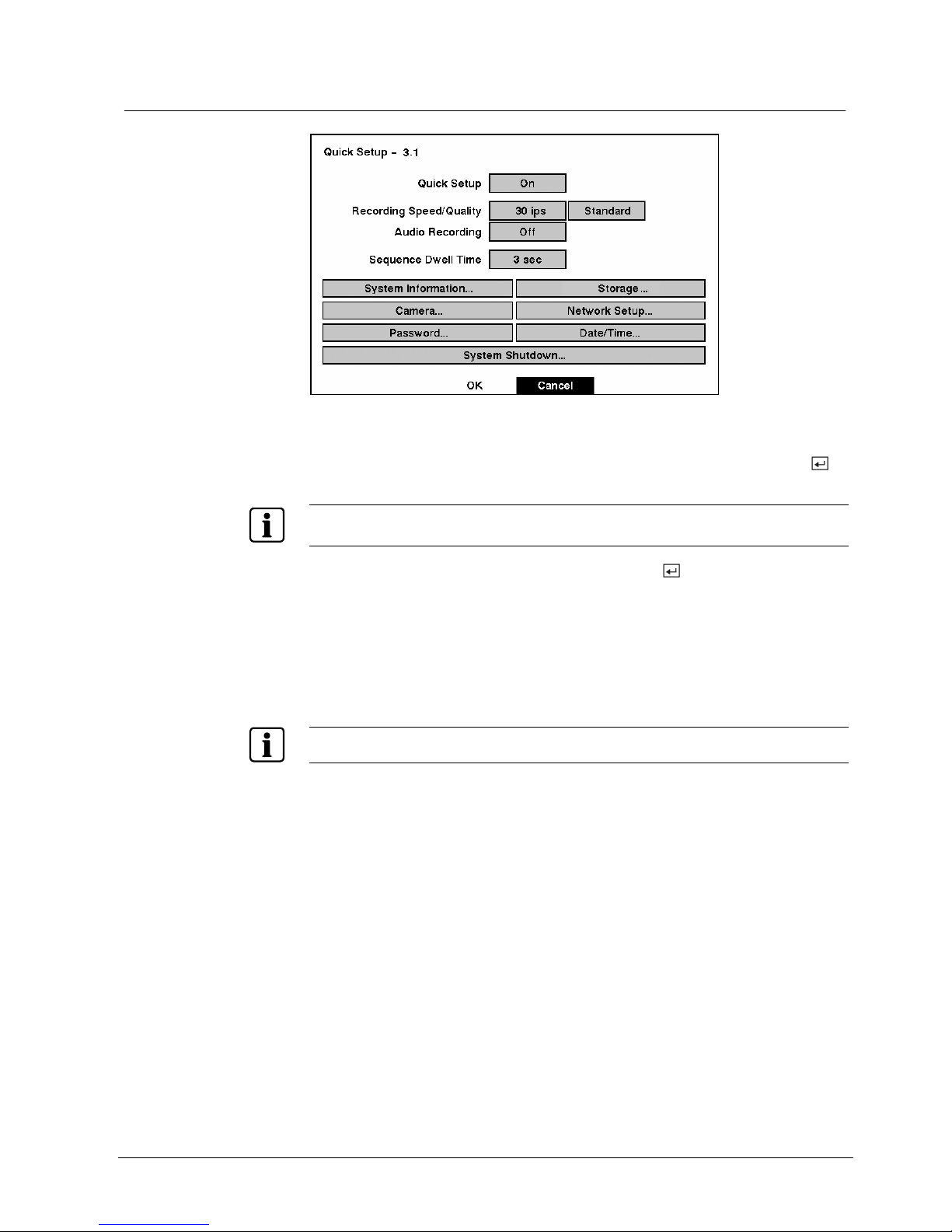
Fig. 19 Quick Setup screen.
The Quick Setup screen allows you to set up the most commonly used features of
your DVR. Use the arrow buttons to move through the options. Pressing the
button lets you make your selections.
NOTE:
If you enter the Quick Setup screen by entering User password, only Password setup will be
permitted.
z Highlight the box beside Quick Setup and press the button to toggle between
On and Off. If you select Off, you will use the Normal Setup screen to change
the DVR’s settings.
z Highlight the Record Speed box and select recording speeds from as few as one
image every 10 seconds to as fast as 50 ips PAL (60 ips NTSC).
z Highlight the Record Quality box and select from Very High, High, Standard and
Low.
z Highlight the box beside Audio Recording and select either On or Off.
NOTE:
It is the user’s responsibility to determine if local laws and regulations permit recording audio.
z Highlight the box beside Sequence Dwell Time and select from 3 to 60 seconds
for the camera sequence dwell time.
z Selecting System Information… enters that screen.
z Selecting Storage… enters a screen where you can check the storage status.
z Selecting Camera… enters a screen where you can set up camera information.
z Selecting Network Setup… enters a screen where you can set up network
information.
z Selecting Password… enters a screen where you will be able to change
passwords.
z Selecting Date/Time… enters a screen where you will be able to set the DVR’s
time and date.
z Selecting System Shutdown… shuts the DVR down. When shutting down the
DVR, you need to confirm that you want to shut down the unit, and you will be
asked for an administrator password.
25
Siemens Building Technologies SISTORE AX9 AX16_EN.doc
Fire & Security Products 09.2004
Configuration
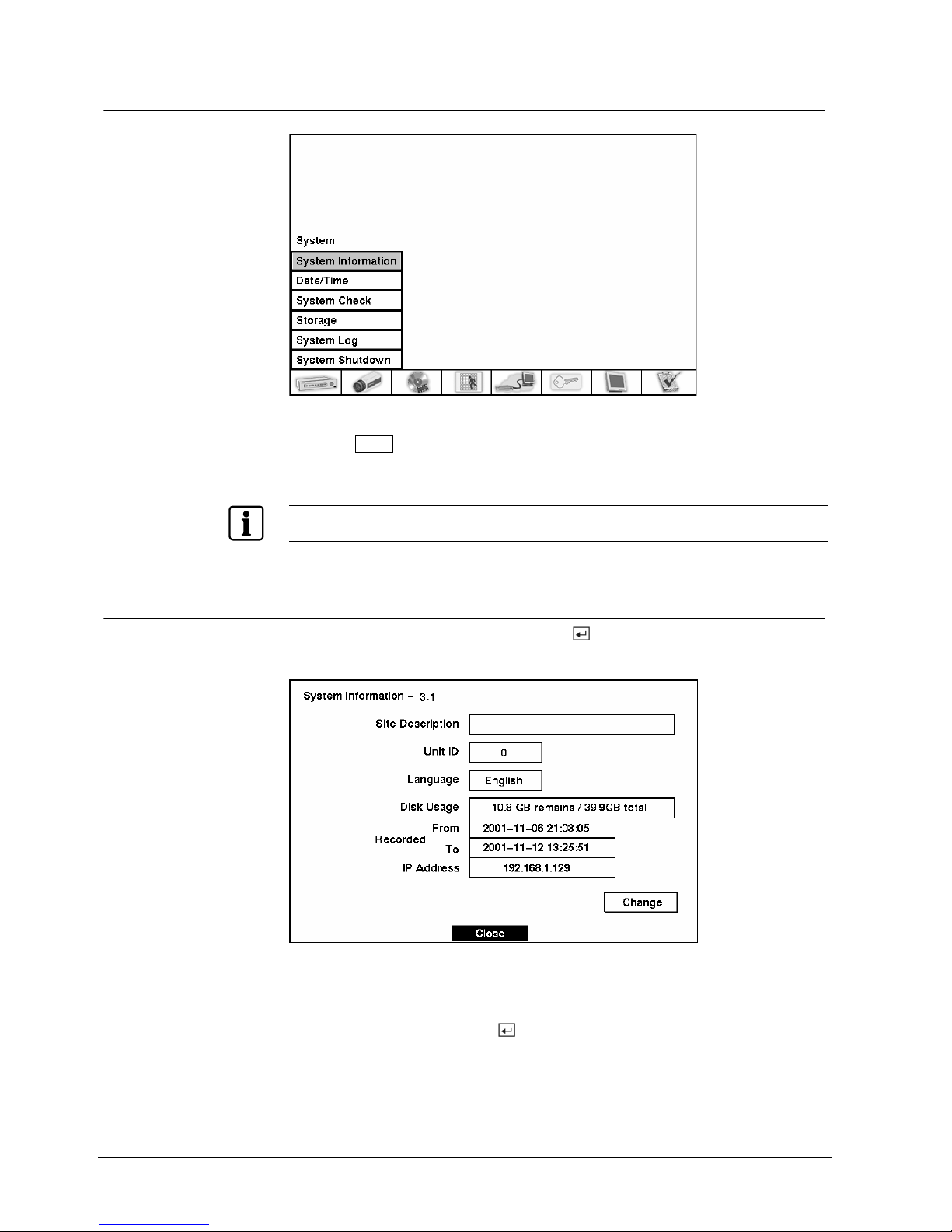
3.5 Normal Setup Screen
Fig. 20 Normal Setup screen.
Press the Menu button to enter the setup screen. If the Quick Setup screen
appears, turn it off as described above. The Normal Setup screen gives you
access to all the DVR’s setup screens.
NOTE:
Switching between Quick Setup and Normal Setup returns their settings to the factory default settings.
3.5.1 System Information
Highlight System Information and press the button. The System Information
screen appears.
Fig. 21 System Information screen.
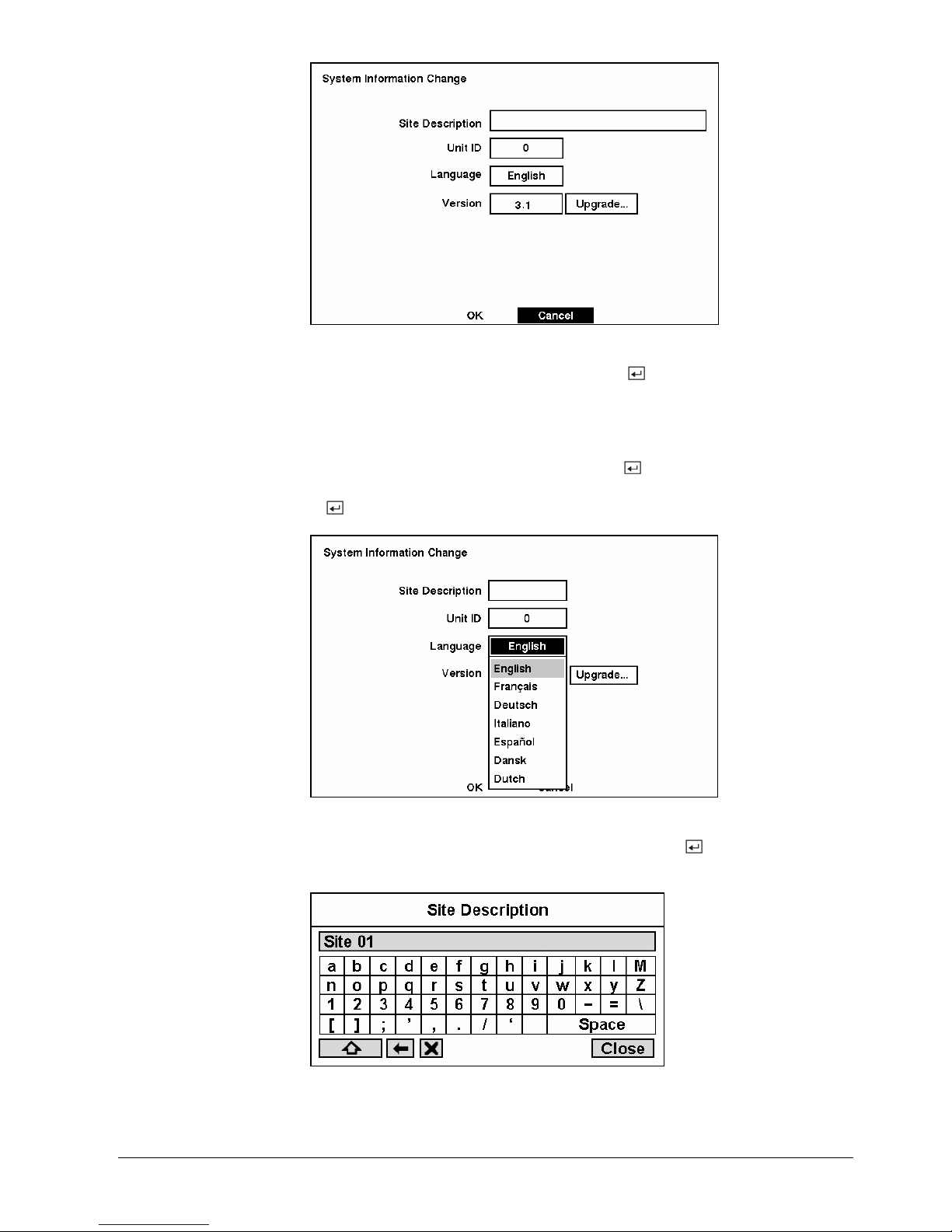
In the System Information screen, you can name the site location, assign a unit ID
number, select the language for the screen display and upgrade the software.
Highlight Change and press the
button. The System Information Change
screen appears.
26
Siemens Building Technologies SISTORE AX9 AX16_EN.doc
Fire & Security Products 09.2004
Configuration
Fig. 22 System Information Change screen.
z Highlight the box beside Unit ID and press the button. Change the number
by highlighting it and using the Up and Down arrow buttons to increase and
decrease the number. The Unit ID number is used to identify the unit when it is
networked with other DVRs. You cannot use the same number for two or more
DVRs that are within the same network.
z Highlight the box beside Language and press
button.
A dropdown menu
displays the available languages. Highlight the desired language and press the
button.
Fig. 23 Language dropdown menu.
z Highlight the box beside Site Description and press the button. A virtual
keyboard displays.
Fig. 24 Virtual keyboard.
27
Siemens Building Technologies SISTORE AX9 AX16_EN.doc
Fire & Security Products 09.2004
Configuration
z Use the arrow keys to highlight the first character you want in the Site Title and
press the
button. That character appears in the title bar and the cursor
moves to the next position. Pressing toggles between the upper and
lower case keyboards, backspaces, and deletes entered characters.
You can use up to 20 characters including spaces in your title.
z Once you have entered your title, highlight Close and press the button.
z After you have created a title, assigned a unit ID number and selected a
language, you can save your changes by highlighting OK and pressing the
button. Selecting Cancel exits the screen without saving the changes.
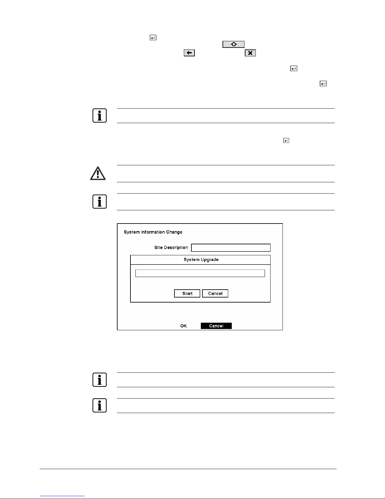
z The box beside Version displays the software version of the DVR.
NOTE:
You can upgrade the software only in the System Information Change screen.
z To upgrade the software, connect the USB device containing the upgrade
package file to the DVR. Highlight Upgrade… and press the
button. The
System Upgrade screen appears. The screen displays the upgrade package file
name.
CAUTION
System upgrade via USB port might NOT be completed properly if the USB
device has been connected to the other USB port. Please remove any other
USB device before system upgrade is attempted.
NOTE:
If the file system on the USB-IDE hard disk drive or USB flash drive is NOT FAT16 or FAT32 format,
format the drive using FAT16 or FAT32 format.
Fig. 25 System Upgrade screen.
z Select Start and enter the Admin password to start the upgrade. The system
restarts automatically after completing the upgrade.
NOTE:
Only the system administrator can upgrade the software.
NOTE:
You cannot upgrade software during clip copy.
28
Siemens Building Technologies SISTORE AX9 AX16_EN.doc
Fire & Security Products 09.2004
 Loading...