

Siemens SISTORE AX4 Lite 1000/100 Configuration & Operation Manual

Siemens AG
Digital Video Recorder
SISTORE AX4 Lite 1000/100
V4.0
Confi
guration &
Operation Manual

Liefermöglichkeiten und technische Änderungen vorbehalten.
Data and design subject to change without notice. / Supply subject to availability.
© 2010 Copyright by Siemens AG
We reserve all rights in this document and in the subject thereof. By acceptance of the document the recipient acknowledges these rights
and undertakes not to publish the document nor the subject thereof in full or in part, nor to make them available to any third party without our
prior express written authorization, nor to use it for any purpose other than for which it was delivered to him.
About this document
This document contains instructions for the configuration and operation of
SISTORE AX4 Lite.
For information on installation please refer to the Installation Manual.
NOTE
This document cannot deal with every possible application. Further useful product information as well
as application examples and supplementary information to the manuals can be found on our intranet
website: https://psp.sbt.siemens.com/
(Product Support Platform).
Trademarks
SISTORE is a trademark of Siemens.
Microsoft is a registered trademark and Windows a trademark of Microsoft
Corporation.
All other product or company names mentioned in this document are trademarks or
registered trademarks of their respective owners and are used only for purposes of
identification or description.
Contacting us
If you have questions or suggestions regarding the product or this documentation,
please contact our Customer Support Center:
Intranet: Customer Support Center
Internet: About us
> Worldwide Contacts
Email: fs.support.sbt@siemens.com
Tel.: +49 89 9221 8000
Fax: +49 89 6367 2000
Training courses
Siemens provides training courses for all products.

3
Siemens AG
06.2010
Contents
1 Safety .......................................................................................................7
1.1 Target readers...........................................................................................7
1.2 Work safety information ............................................................................7
1.2.1 Transport...................................................................................................8
1.2.2 Installation.................................................................................................8
1.2.3 Service and maintenance .........................................................................9
1.3 Meaning of the written warning notices ....................................................9
1.4 Meaning of the hazard symbols................................................................9
2 Directives and standards .....................................................................10
3 Technical data .......................................................................................11
4 Details for ordering...............................................................................12
5 Scope of delivery ..................................................................................12
6 Description of functions.......................................................................13
7 Configuration.........................................................................................15
7.1 Front panel controls ................................................................................15
7.2 Remote controls......................................................................................17
7.3 Turning on the power ..............................................................................17
7.4 Initial unit setup .......................................................................................18
7.5 Logging out .............................................................................................18
7.6 Setup screen...........................................................................................19
7.7 Recording settings ..................................................................................20
7.7.1 Record screen.........................................................................................20
7.7.2 Schedule screen .....................................................................................22
7.7.3 Pre-Event screen ....................................................................................25
7.8 Network setup .........................................................................................26
7.8.1 Network screen .......................................................................................27
7.8.2 LAN setup screen....................................................................................32
7.8.3 DDNS ......................................................................................................35
7.9 Event settings..........................................................................................36
7.9.1 Alarm-In screen.......................................................................................36
7.9.2 Motion Detection screen .........................................................................39
7.9.3 Video Loss screen...................................................................................43
7.9.4 Video Blind screen ..................................................................................45
7.9.5 Text-In screen .........................................................................................47
7.9.6 System Event screen ..............................................................................51
7.9.7 Event status ............................................................................................54
7.10 Display ....................................................................................................55
7.10.1 OSD screen.............................................................................................55
7.10.2 VGA.........................................................................................................57
7.10.3 Main Monitor screen ...............................................................................58
7.11 Configuring devices.................................................................................59
7.11.1 Camera setup screen..............................................................................59
7.11.2 Audio Setup.............................................................................................61
7.11.3 Alarm-Out screen....................................................................................62
7.11.4 Remote Control screen ...........................................................................64

4
Siemens AG
06.2010
7.12 Storage Setup .........................................................................................65
7.12.1 Storage Information.................................................................................65
7.12.2 Storage Status ........................................................................................66
7.13 System ....................................................................................................68
7.13.1 Information screen ..................................................................................68
7.13.1.1 Upgrading the software..........................................................................69
7.13.1.2 Importing settings...................................................................................70
7.13.1.3 Exporting settings...................................................................................70
7.13.1.4 Showing System Log .............................................................................71
7.13.2 Date/Time setup......................................................................................72
7.13.3 User setup screen ...................................................................................75
7.13.4 Shutdown… screen.................................................................................77
8 Operation ...............................................................................................78
8.1 Turning on the power ..............................................................................78
8.2 Live Monitoring Menu..............................................................................78
8.2.1 Freeze Mode ...........................................................................................79
8.2.2 Sequence Mode ......................................................................................79
8.2.3 Camera Menu .........................................................................................80
8.2.3.1 PTZ mode................................................................................................80
8.2.3.2 Zoom mode .............................................................................................83
8.2.3.3 Audio .......................................................................................................83
8.2.3.4 Colour Control .........................................................................................83
8.2.4 Alarm Reset.............................................................................................83
8.2.5 Panic .......................................................................................................83
8.2.6 Setup.......................................................................................................84
8.2.7 Search Mode...........................................................................................84
8.2.8 Login/Logout ...........................................................................................84
8.2.9 Event monitoring .....................................................................................84
8.2.10 Covert camera.........................................................................................84
8.3 Using a mouse ........................................................................................85
8.4 Recording video ......................................................................................86
8.5 Recording Audio......................................................................................86
8.6 Playing recorded video............................................................................87
8.7 Searching video ......................................................................................88
8.7.1 Search Menu...........................................................................................89
8.7.1.1 Event Log Search....................................................................................89
8.7.1.2 Record Table Search ..............................................................................91
8.7.1.3 Motion Search .........................................................................................93
8.7.1.4 Text-In Search.........................................................................................95
8.7.2 Go To Menu ............................................................................................97
8.7.3 Export......................................................................................................98
8.7.4 Camera Menu .......................................................................................100
8.7.5 Alarm Reset...........................................................................................101
8.7.6 Panic .....................................................................................................101
8.7.7 Data Source ..........................................................................................101
8.7.8 Exit ........................................................................................................101
9 Troubleshooting..................................................................................102
10 Disposal ...............................................................................................103

5
Siemens AG
06.2010
11 Appendix..............................................................................................104
11.1 Preparing the USB hard disk drive in Windows 2000...........................104
11.2 Text-In Search Examples......................................................................105
11.2.1 Search Example I..................................................................................105
11.2.2 Search Example II.................................................................................106
11.3 Web Client.............................................................................................107
11.3.1 Web View Mode....................................................................................108
11.3.2 Web Play Mode.....................................................................................110
11.4 Recording tables ...................................................................................112
11.4.1 Recording times with 250 GB HDD (days) for PAL images..................112
11.4.2 Recording times with 250 GB HDD (days) for NTSC images...............113
11.5 Map of screens......................................................................................114
11.6 System log notices................................................................................115
11.7 Error code notices.................................................................................116


Safety
7
Siemens AG
06.2010
1 Safety
1.1 Target readers
The instructions in this document are designed only for the following target readers:
Target readers Qualification Activity
Installer Technical training for building
or electrical installations.
Installs the product, individual
components of the product or
replacement parts.
Operational startup
personnel
Technical training for building
or electrical installations.
Training on the product is
recommended.
Puts the product into operation for
the first time, or changes the
existing configuration.
End user Has working knowledge of
computers.
Instruction by technical
specialists is necessary.
Performs only the procedures for
proper operation of the product.
Service personnel Technical training for building
or electrical installations.
Checks the product at regular
intervals to ensure that it is in good
working order and performs service
work.
1.2 Work safety information
z Read the general safety precautions before operating the device.
z Keep this document for reference.
z Follow all warnings and instructions marked on the device.
z Always pass this document on together with the device.
z Any national or local safety standards or laws that apply to the development,
design, installation, operation or disposal of a product must be adhered to in
addition to the instructions in the product documentation.
Radio interference with other devices in the environment
z This is a Class A device. This equipment may cause radio interference in a
residential installation. In this case the user is encouraged to perform appropriate
measures to correct the interference.
Liability claim
z Do not connect the device if it is damaged or any parts are missing.
z Do not make any changes or modifications to the device unless they have been
approved by the manufacturer.
z Use only spare parts and accessories that have been approved by the
manufacturer.

Safety
8
Siemens AG
06.2010
1.2.1 Transport
Damage during transport
z Keep the packaging material for future transportation.
z Do not expose the device to mechanical vibrations or shocks.
1.2.2 Installation
Damage due to unsuitable mounting location
z The environmental conditions recommended by the manufacturer must be
observed (see Section 3: Technical data).
z Do not operate the device close to sources of powerful electromagnetic radiation.
z Do not operate the device in dusty places.
z The device should only be used for indoor applications.
z Do not expose the device to mechanical vibrations or shocks.
z Protect the device against moisture.
Cable damage due to mechanical load
z Make sure that cables are not under stress, kinked or damaged.
Damage to the device due to lack of ventilation
z Do not block or cover the ventilation openings of the device.
z Do not stack several devices on top of each other and do not place any objects on
the device.
z Place this equipment only in an upright position. This equipment has an open-
frame Switching Mode Power Supply (SMPS), which can cause a fire or electric
shock if anything is inserted through the ventilation holes on the side of the
equipment.
Danger of electrical shock due to incorrect connection
z Use the device only in conjunction with a power supply cable that has been
approved in your country and complies with the national standards.
z This product is designed for TN power systems and for IT power systems in
Norway with 230 V phase-to-phase voltage. Do not connect the device to any
other IT power systems.
Damage to the device due to overvoltage
z Connect the device only to power sources with the specified voltage. Voltage
supply requirements can be found on the type label (see Section 3: Technical
data).
Safety
9
Siemens AG
06.2010
1.2.3 Service and maintenance
Danger of electrical shock during maintenance
z Always disconnect the power cable and other cables from the main power supply
before performing maintenance.
Danger of electrical shock while cleaning the device
z Disconnect the device from the mains supply before cleaning.
z Do not use liquid cleaners or sprays that contain alcohol, spirit or ammonia.
1.3 Meaning of the written warning notices
The severity of a hazard is indicated by the following written warning notices.
Signal word Type of risk
CAUTION There is a risk of minor injuries or damage to property.
1.4 Meaning of the hazard symbols
The nature of the hazard is indicated by icons.
Warning of a hazard

Directives and standards
10
Siemens AG
06.2010
2 Directives and standards
This product complies with the requirements of the following European directives.
The EU declaration of conformity is available to the responsible agencies at:
Siemens AG
76181 Karlsruhe
Germany
European Directive 2004/108/EC "Electromagnetic Compatibility"
Compliance with the European Directive 2004/108/EC has been proven by testing
according to the following standards:
Emitted interference: EN 61000-6-4
EN 55022 Class A
Interference resistance: EN 50130-4
European Directive 2006/95/EEC "Low-Voltage Directive"
Compliance with the European Directive 2006/95/EEC has been proven by testing
according to the following standard:
Safety: EN 60950-1

Technical data
11
Siemens AG
06.2010
3 Technical data
Monitoring
Video inputs Composite: 4 looped through, BNC, PAL/NTSC (auto detection)
Video outputs 1 Composite (BNC)
1 VGA: 800 x 600, 1024 x 768, 1280 x 1024 (60 Hz)
Video resolution 720 x 576 (PAL), 720 x 480 (NTSC)
Display mode 1, 4, Sequence, Digital Zoom, Freeze, Covert
Inputs/Outputs
Audio inputs 4 line level RCA
Audio output 1 line level RCA
Alarm inputs 4, NC or NO, TTL
Alarm outputs 1 relay output, NC or NO, 2 A (125 V AC), 1 A (30 V DC)
Alarm reset input 1
Network Ethernet (10/100 BaseT)
Interfaces Front buttons, mouse, remote keyboard, IR remote control, RAS software
Auxiliary inputs/outputs RS232, RS485, USB 2.0
Internal buzzer 80 dB at 10 cm
Record/Playback
Compression H.264 technology (video), ADPCM (audio)
Recording speed Standard resolution: up to 100 ips (PAL), 120 ips (NTSC)
High resolution: up to 50 ips (PAL), 60 ips (NTSC)
4CIF resolution: up to 25 ips (PAL), 30 ips (NTSC)
Recording resolution CIF, 2CIF, 4CIF
Recording mode Time-Lapse, Event, Pre-Event (up to 30 min.), Text-In, Panic
Search mode Date/Time, Calendar, Event, Motion, Museum, Text-In, Record Table
System
Operating system Embedded Linux (built-in flash memory)
Hard disk capacity 1 internal hard disk drive: 1000 GB SATA
Backup recording media USB (hard disk drive, CD burner, flash memory)
Disk management Temperature check, SMART diagnosis, operation without hard disk drive

Details for ordering
12
Siemens AG
06.2010
Specifications
Power requirements 100 – 240 V AC, 0.8 – 0.4 A, 50/60 Hz ± 10 %
Power consumption Max. 25 W
Ambient temperature, operating 5 – 40 °C
Relative humidity 0 – 90 %, no condensation
Dimensions (W x H x D) 340 x 46.5 x 310 mm
Approvals CE, FCC, C-Tick, RoHS
4 Details for ordering
Type Order No. Designation Weight
SISTORE AX4 Lite 1000/100 S54569-C51-A3 SISTORE AX4 Lite, 1000 GB, 100 ips 4.5 kg
5 Scope of delivery
z Digital video recorder
z Power cord
z CD-ROM including:
Configuration & Operation Manual,
Multilingual RAS Software and User Manual
z Multilingual Installation Manual
z Infrared remote control (including battery)

Description of functions
13
Siemens AG
06.2010
6 Description of functions
SISTORE AX is a digital video recording system for the surveillance of rooms,
premises, buildings, production workshops, critical public areas or any outdoor areas
where security is important.
The DVR converts analog PAL or NTSC video to digital images and records them on
a hard disk drive. The technology also allows you to view recorded video while the
DVR continues recording video.
Digitally recorded video has several advantages. You can freeze frames, fast
forward, fast reverse, slow forward and slow reverse without image streaking or
tearing. Digital video can be indexed by time or events, and you can instantly view
video after selecting the time or event.
Your DVR can be set up for event or time-lapse recording. You can define times to
record, and the schedule can change for different days of the week and user defined
holidays.
The DVR can be set up to alert you when the hard disk drive is full, or it can be set to
record over the oldest video once the disk is full.
Your DVR uses a proprietary encryption scheme making it nearly impossible to alter
video.
You can view video and control your DVR remotely by connecting via Ethernet.
There is a USB port that can be used to upgrade the system or copy video clips to
external hard disk, CD-RW and flash drives.
Your colour digital video recorder (DVR) provides recording capabilities for four
camera inputs. It provides exceptional picture quality in both live and playback
modes, and offers the following features:
– Efficient video compression through “H.264 Technology”
– 4 composite video input connectors
– Compatible with colour (PAL or NTSC) and B/W (CCIR and EIA-170) video
sources
– Auto-detection for PAL and NTSC
– Monitor connectors: 1 BNC Video Out, 1 VGA
– Multiple search engines (date/time, calendar, event, motion, museum, text-in)
– Records up to 100/120 images per second (PAL/NTSC)
– “Loop-through” video connectors
– Continuous recording in disk overwrite mode
– 1 USB 2.0 port
– Continues recording while transmitting to remote site and during playback
– User-friendly Graphical User Interface (GUI) menu system
– Multiple recording modes (time-lapse, pre-event, alarm, motion and panic)
– Two-way audio communication
– 4-channel audio recording and 1-channel audio playback

Description of functions
14
Siemens AG
06.2010
– Text input for Automated Teller Machine and Point of Sales
– Alarm connections include: input, output and reset input
– Built-in alarm buzzer
– Live or recorded video access via Ethernet
– Time synchronization using industry standard protocol
– Self-diagnostics with automatic notification including hard disk drive S.M.A.R.T.
protocol
– Infrared remote control
Configuration
15
Siemens AG
06.2010
7 Configuration
NOTE
Your DVR should be completely installed before proceeding. For further information please refer to the
Installation Manual.
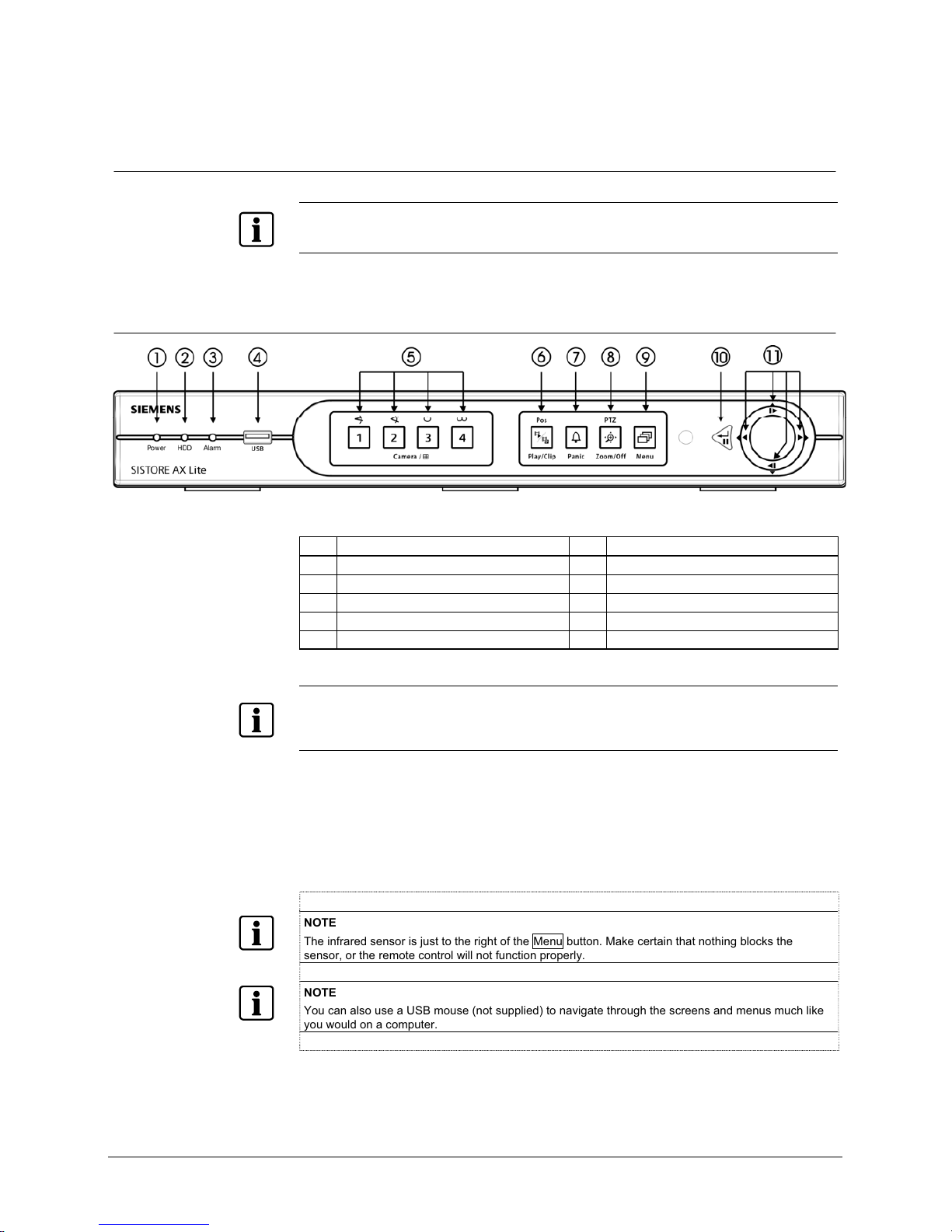
7.1 Front panel controls
Fig. 1 DVR front panel
1 Power LED 7 Panic button
2 HDD LED 8 PTZ/Zoom button
3 Alarm Out LED 9 Menu button
4 USB connector 10 Enter/Pause button
5 Camera buttons 11 Arrow buttons
6 Play/Clip button
NOTE
A separate Alarm button is not provided. Pressing any keys on the front panel or remote control resets
alarm output including the internal buzzer when the alarm is activated. However, when you are in the
menu or PTZ mode, you have to exit the menu or PTZ mode first to reset alarm output.
The front panel looks and operates much like a VCR combined with a multiplexer.
Many of the buttons have multiple functions. The buttons on the infrared remote
control, while laid out differently, perform the same functions as those on the front
panel. The following describes each button and control. Take a few minutes to
review the descriptions. You will use these to initially set up your DVR and for daily
operations.
NOTE
The infrared sensor is just to the right of the Menu button. Make certain that nothing blocks the
sensor, or the remote control will not function properly.
NOTE
You can also use a USB mouse (not supplied) to navigate through the screens and menus much like
you would on a computer.
Power LED The Power LED is lit when the unit is On.
HDD LED The HDD LED flickers when the DVR is recording or searching
video on the hard disk drive.

Configuration
16
Siemens AG
06.2010
Alarm Out LED The Alarm LED is lit when alarm output or internal buzzer is
activated.
USB connector A USB port on the front panel is provided to connect external hard
disk, CD-RW or flash drives for video clip copying or system
upgrades. Position external drives close enough to the DVR so that
you can make the cable connections, usually less than 6 feet. Use
the USB cable provided with the hard disk drive to connect it to the
DVR.
A USB mouse (not supplied) can be connected to the USB port. You
can use the mouse to navigate through the screens and menus
much like you would on a computer.
A USB to Serial converter can be connected to the USB port.
Multiple text-in devices can be used with a USB to Serial converter.
Camera buttons
(1 to 4)
Pressing the individual camera buttons will cause the selected
camera to display full screen, and pressing the button again
changes the display format to the quad (2x2) mode. Buttons 1 to 4
are also used to enter passwords.
In the PTZ mode, pressing the button 1 zooms in the screen and the
button 2 zooms out the screen, and pressing the button 3 focuses
near and button 4 focuses far.
Play/Clip button
Pressing the Play/Clip button enters the playback mode, and
pressing the button again exits the playback mode. When entering
the playback mode, video is paused. Pressing the
arrow button
plays back video at regular speed. The screen displays when the
DVR is in the Pause mode and the screen displays
when the
DVR is playing back video. The button is also used to load a Preset
View in the PTZ mode.
Pressing and holding the Play/Clip button for three seconds or
longer allows you to copy video clips.
Panic button
Pressing the Panic button starts panic recoding of all camera
channels, and displays on the screen. Pressing the button again
will stop panic recording.
NOTE
When the DVR does not detect a VGA monitor automatically, pressing and holding the Panic button
on the front panel for 5 seconds or longer switches the video output to VGA out manually.
PTZ/Zoom button
In the live monitoring mode, pressing the PTZ/Zoom button enters
the PTZ mode, and pressing the button again exits the PTZ mode
and enters the zoom mode. When in the zoom mode, pressing the
button again exits the zoom mode.
When in the PTZ mode, pressing the arrow buttons or Menu button
allows you to control properly configured cameras.
When in the zoom mode, a rectangle displays on the screen. A
rectangle shows the area that will be enlarged. You can move the
rectangle around using the arrow buttons. Pressing the
(Enter)
button in enlarges the area in rectangle.
NOTE
Pressing the PTZ/Zoom button enters directly the zoom mode if there is no PTZ camera you set up in
the Camera setup.
Menu button
Pressing the Menu button enters the Setup screen. You will need to
enter the authorized user and password to access Setup. Pressing
the button also closes the current menu or setup dialog box. In the
Playback mode, pressing the button displays the Search menu.
Pressing and holding the button for three seconds or longer displays
live channels sequentially.
Configuration
17
Siemens AG
06.2010
Enter/Pause button
When in the setup mode, pressing the
button selects a
highlighted item or completes an entry that you have made.
In the live monitoring mode, pressing the button freezes the current
screen and the screen displays
icon. When in the playback
mode, pressing the button pauses playing video.
Up, Down, Left, Right Arrow
buttons
These buttons are used to navigate through menus and GUI.
The Up and Down arrow buttons are also used to change numbers
by highlighting a number in the menu and by increasing or
decreasing the number’s value.
These buttons are also used to control Pan and Tilt when in the PTZ
mode. In the playback mode, pressing the
button plays video
backward at high speed. Pressing the button again toggles the
playback speed from
, and , and the screen displays
, and respectively. While playing video, pressing
the
button plays video forward at high speed. Pressing the button
again toggles the playback speed from , , and , and
the screen displays
, , and respectively. When in
the pause mode, pressing the
button moves to the next image
and pressing the
button moves to the previous image.
ID button on remote control If a DVR System ID is set to 0, the infrared remote control will
control that DVR without any additional operations. (Refer to Section
7.13.1: Information screen for further information on setting the
S
ystem ID.) If the system ID is 1 to 4, you must to press the ID
button on the remote control and then press the number button (1 to
4) in order to control that DVR. If the System ID of two or more
DVRs is set to 0, those DVRs will react to the infrared remote
control at the same time.
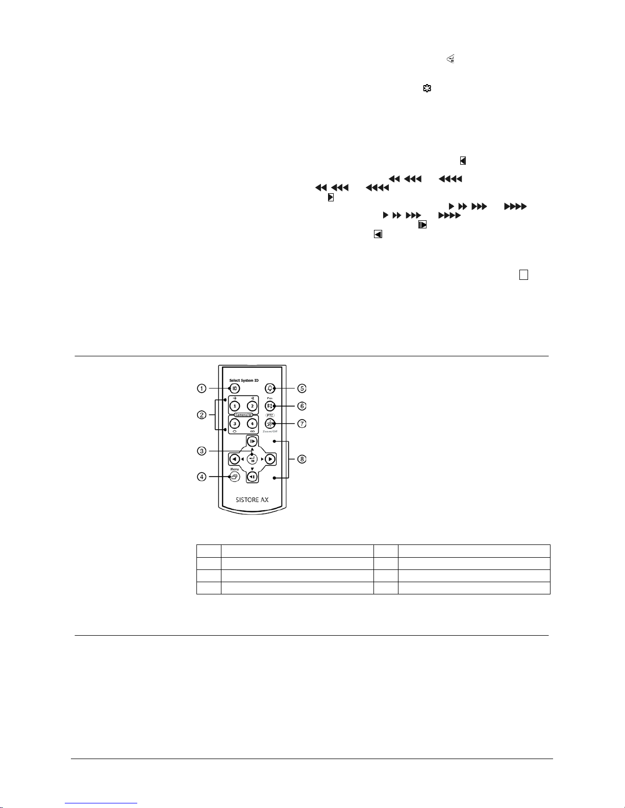
7.2 Remote controls
Fig. 2 Infrared remote control
1 ID button 5 Alarm button
2 Camera buttons 6 Play/Clip button
3 Enter/Pause button 7 PTZ/Zoom button
4 Menu button 8 Arrow buttons
7.3 Turning on the power
Connecting the power cord to the DVR turns on the unit. The unit takes
approximately 60 seconds to initialize.
Configuration
18
Siemens AG
06.2010
7.4 Initial unit setup
Before using your DVR for the first time, you will want to establish the initial settings.
This includes items such as time and date, display language, camera, remote
control, record mode, network and password. Your DVR can be set up using various
screens and dialog boxes.
Throughout the screens you will see
. Highlighting the and pressing the button
gives you the opportunity to reset that screen to its default settings.
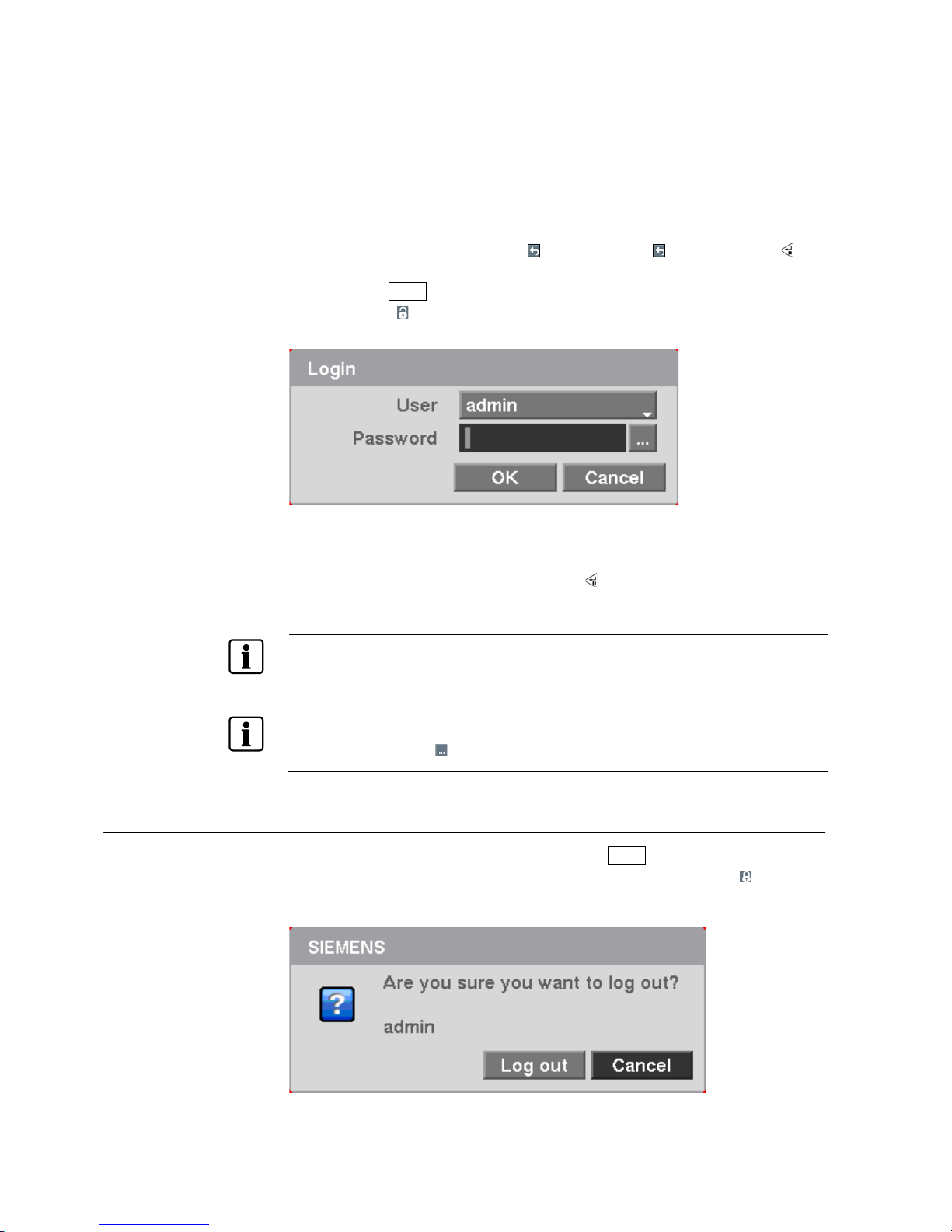
1. Press the Menu
button or move the mouse pointer to the top of the screen and
then select (Login) in the Live Monitoring menu to enter the setup screens.
Î The Login screen appears.
Fig. 3 Login screen
2. Select a User and enter the password by pressing the appropriate combination
of Camera number buttons and then the
button.
There is no default password when logging in the admin user for the first time.
NOTE
To assure the secure management of the system, setting up a password is strongly recommended.
NOTE
You can use a mouse (not supplied) to access the Login screen in addition to using the front panel
buttons or the infrared remote control. Click the right mouse button to display the Login screen. To
enter a password, click the
button, and the virtual keyboard displays. See instructions below for
using the virtual keyboard.
7.5 Logging out
1. To log the user out of the system, press the Menu button on the front panel or
move the mouse pointer to the top of the screen and then select (Logout) in
the Live Monitoring menu. The Logout screen displays asking you to confirm
whether or not you want to log out the current user.
Fig. 4 Logout screen
Configuration
19
Siemens AG
06.2010
7.6 Setup screen
Fig. 5 Setup screen
Press the Menu
button on the front panel or move the mouse pointer to the top of
the screen and then select (Setup) in the Live Monitoring menu to enter the setup
screen.
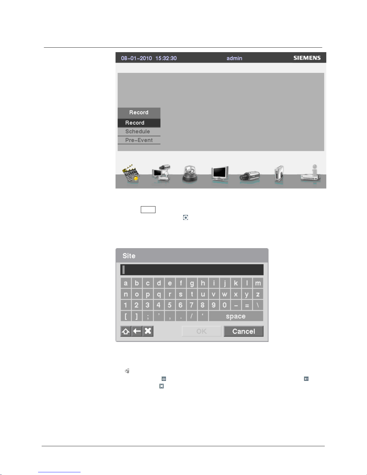
While setting up the DVR, there will be many opportunities to enter names and titles.
When making these entries, a Virtual Keyboard will appear.
Fig. 6 Virtual Keyboard
Use the arrow keys to highlight the character you want in the name or title and press
the
button. That character appears in the title bar and the cursor moves to the next
position. Pressing
toggles between the upper and lower case keyboards,
backspaces, and
deletes entered characters. You can use up to 31 characters
including spaces in your title.
Special characters can be created using ^ and a capital letter; e.g., ^J for NL (New
Line), ^M for CR (Carriage Return). Special characters are commonly used by text
input devices and will be useful when performing Text-In Searches.
Configuration
20
Siemens AG
06.2010
7.7 Recording settings
Your DVR offers a variety of flexible recording modes. You can set it up to record all
the time or to only record events. It can be set up to continue recording once the
hard disk drive is full by recording over the oldest video, or you can set it up to alert
you when the hard disk is full and stop recording.
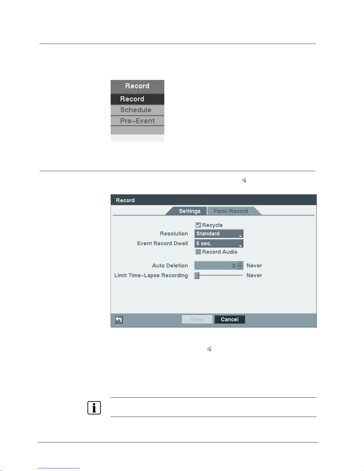
Fig. 7 Record menu
7.7.1 Record screen
Highlight Record in the Record menu and press the button.
Î The Record setup screen appears.
Fig. 8 Record setup screen
Highlighting Recycle and pressing the
button toggles between On and Off. In the
Recycle mode, the DVR records over the oldest video data once all available
storage space has been used. When Recycle is turned off, the DVR stops recording
once all available storage space has been used.
1. Highlight the Resolution box and select from “Very High”, "High" and
"Standard".
NOTE
The total ips of all camera channels will be limited to 50 ips (60 ips for NTSC) when set to High
resolution and 25 ips (30 ips for NTSC) when set to Very High resolution.
Configuration
21
Siemens AG
06.2010
NOTE
When set to High or Very High resolution, the maximum recording speed of each camera channel
decreases by half. However the maximum recording speed of 25 ips (30 ips for NTSC) will maintain if
the number of cameras that are turned On is two or less.
No. of cameras set to On and High or Very High resolution
0 1 2 3 4
25 ips 25 ips 12.5 ips 12.5 ips
NOTE
The DVR will NOT record audio when the record speed is set to less than 1 ips.
2. Highlight the Event Record Dwell box and set the length of time you would like
to record for the associated event.
Î You can set the dwell from 5 seconds to 15 minutes.
Refer to the System Event - Actions screen in Section 7.9.6 for information
rega
rding event recording.
3. Highlight the slide bar beside Auto Deletion, and use the Left and Right arrow
buttons to adjust the length of time recorded data will be kept from 1 to 99 days.
Î The DVR automatically deletes video recorded earlier than the user-defined
period under three conditions: at midnight, whenever the system reboots or
whenever the user changes the Auto Deletion settings. Selecting "Never" will
disable the Auto Deletion function.
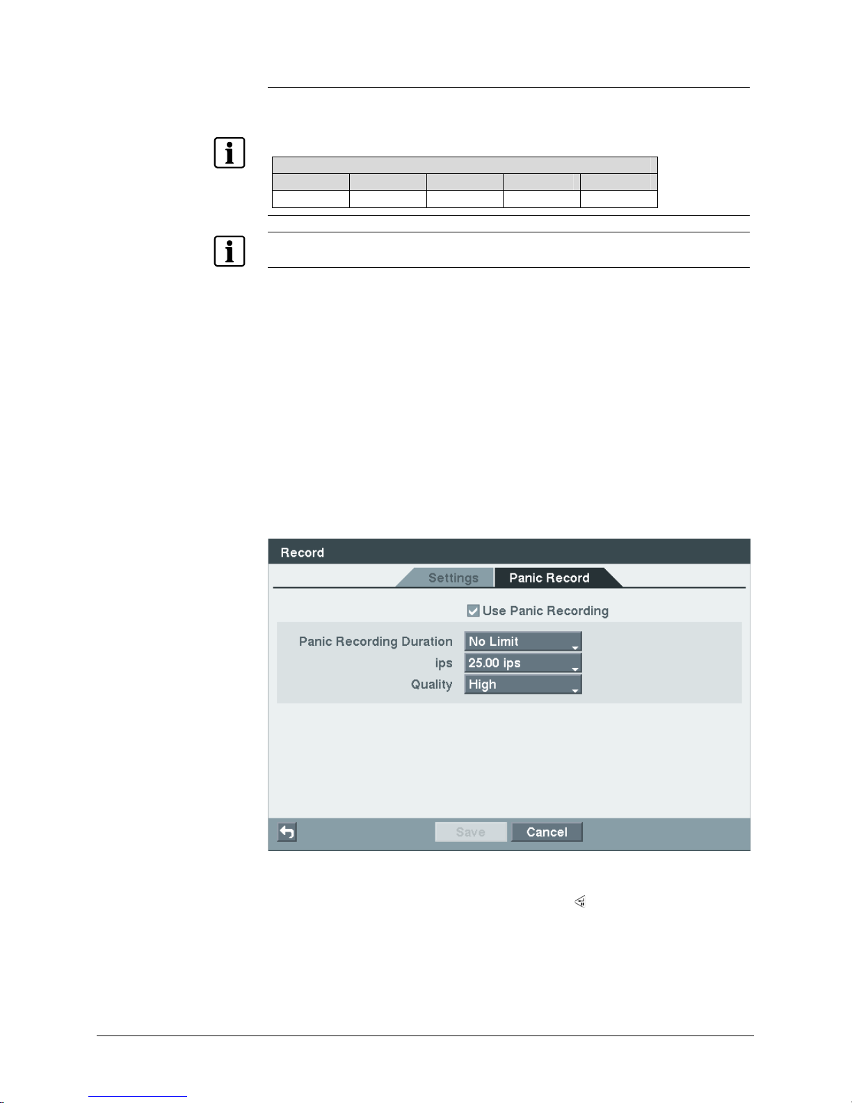
4. Highlight the Panic Record tab.
Î The Panic Record setup screen appears.
Fig. 9 Record setup screen
Highlighting Use Panic Recording and pressing the
button toggles between On
and Off.
1. Highlight the Panic Recording – Duration box and set the duration of panic
recording.
Configuration
22
Siemens AG
06.2010
Î
Panic recording will stop automatically after the preset duration as long as the
Panic button is not pressed to stop the panic recording. You can set the dwell
from 5 minutes to 1 hour. Select "No Limit" if you want to stop panic recording
manually.
Highlighting the Panic Recording – ips box and pressing the
button allows
you to set the images per second for Panic recording. You can select from 0.10
to 25.0 (30.0 for NTSC) images per second.
Highlighting the Panic Recording – Quality box and pressing the
button
allows you to set the recorded image quality for Panic recording. You can select
from: Very High, High, Standard and Basic.
Î You can save your Record settings by highlighting Save and pressing the
button.
Î Selecting Cancel exits the screen without saving the changes.
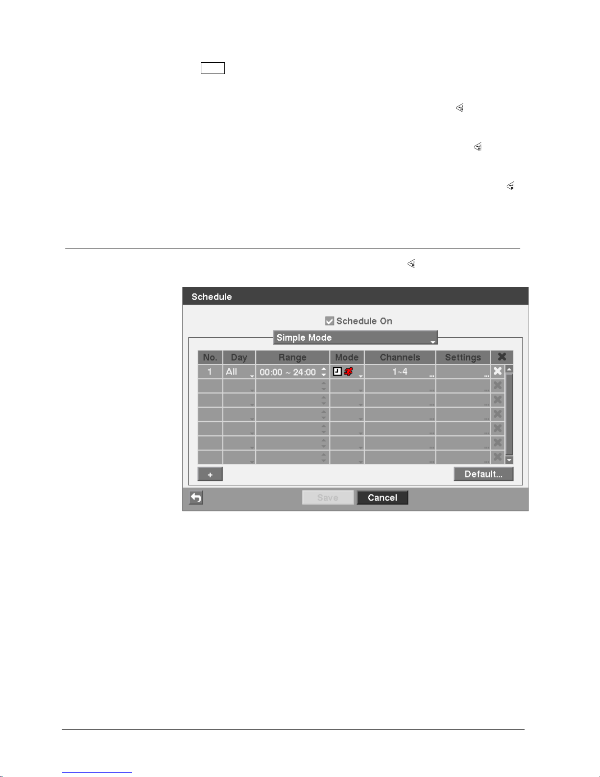
7.7.2 Schedule screen
Highlight Schedule in the Record menu and press the button.
Î The Schedule setup screen appears.
Fig. 10 Schedule setup screen (Simple Mode)
Configuration
23
Siemens AG
06.2010
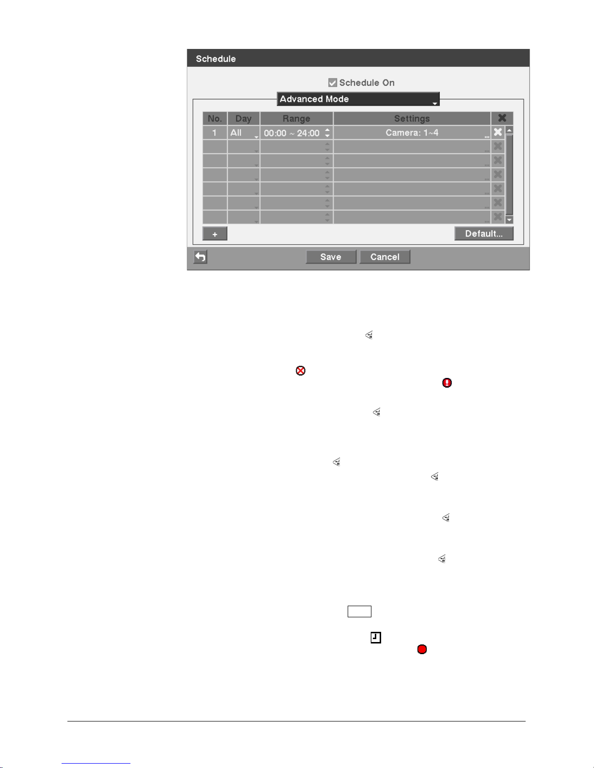
Fig. 11 Schedule setup screen (Advanced Mode)
You can program the DVR to record only during certain times based on time, day of
the week, and holidays. The smallest time segment you can use is 15 minutes.
Highlighting Schedule On and pressing the
button toggles between On and Off. In
the Schedule On mode, the DVR records video based on the schedule established
in the Schedule screen. When turning Schedule recording Off, you will be asked to
confirm your decision, and
displays at the top-left corner of each camera screen.
Panic recording will function even when Schedule is turned off.
displays during
panic recording.
Highlighting Schedule Mode and pressing the
button allows you to select between
Simple Mode and Advanced Mode. Selecting Advanced Mode allows you to set up
an individual recording schedule for each event.
1. Highlight the "+" and press the button to add a schedule item.
2. Highlight the box under the Day heading and press the
button to change the
days that the scheduled recording will take place.
Î Choose from: Sun, Mon, Tue, Wed, Thu, Fri, Sat, M~F, Hol and All.
3. Highlight the box under the Range heading and press the
button to change
the time range that the scheduled recording will take place.
Î The smallest time segment you can use is 15 minutes.
4. Highlight the box under the Mode heading and press the
button to change
the recording mode that will be used.
Î Choose from: No Record, Time, Event and Time & Event (Simple Mode only).
When the DVR is in the No Record mode, it will not record during the preset
day and time range as long as the
Panic
button is not pressed. Use the No
Record mode when you do NOT want the DVR to record during certain times.
When the DVR is in the Time mode, the
icon displays at the top-left corner
of the screen. The DVR will record and displays the
icon at the top-left
corner of the screen during the scheduled times.
Configuration
24
Siemens AG
06.2010
When the DVR is in the Event mode, the red icon displays at the top-left
corner of the screen. The DVR will record and displays the
icon at the topleft corner of the screen when any event occurs. When the DVR is in the PreEvent recoding mode, the yellow
icon displays when there is no event, and
the DVR is not recording. When the DVR is in the Pre-Event mode, the red
and
display when any event occurs and the DVR starts recording.
When the DVR is in the Time & Event mode, the DVR will follow the Time
settings and the
icon displays. The DVR follows the Event settings and the
icon displays.
5. Highlight the box under the Channels heading and press the
button to select
which cameras will be recorded (Simple Mode only).
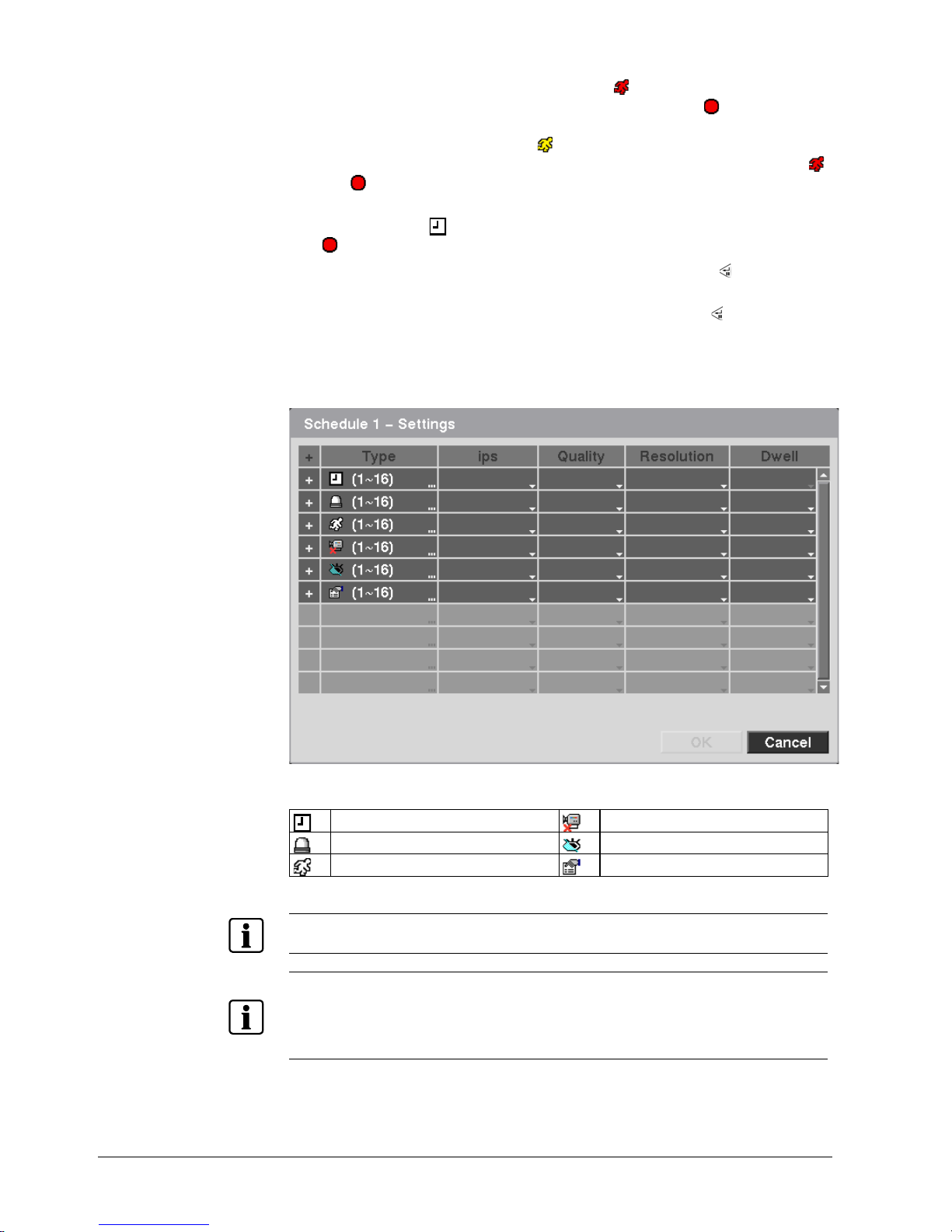
6. Highlight the box under the Settings heading and press the
button to define
the recording settings.
Î You can set the ips and quality of the recording for any modes you set up in the
Mode column. If you do not set the ips and quality in the Settings column, the
DVR will follow the default settings. See below for details.
Fig. 12 Schedule – setup screen (Advanced Mode)
Time-lapse (Time)
Video Loss
Alarm-In
Video Blind
Motion
Text-In
NOTE
Channels that are not defined will use the setting values of the previous schedule item..
NOTE
When multiple events are detected at the same time from a specific channel, the DVR will record
event video with the high setting values if the ips, Quality, Resolution and Dwell values of events are
different from each other. However, the ips will be reset to the supported maximum value when the
ips, Quality, Resolution and Dwell are set to the highest value (Advanced Mode only).
Configuration
25
Siemens AG
06.2010
7. Highlight the box under the heading and press the button to delete the
recording settings.
Î You will be asked to confirm that you want to delete the settings.
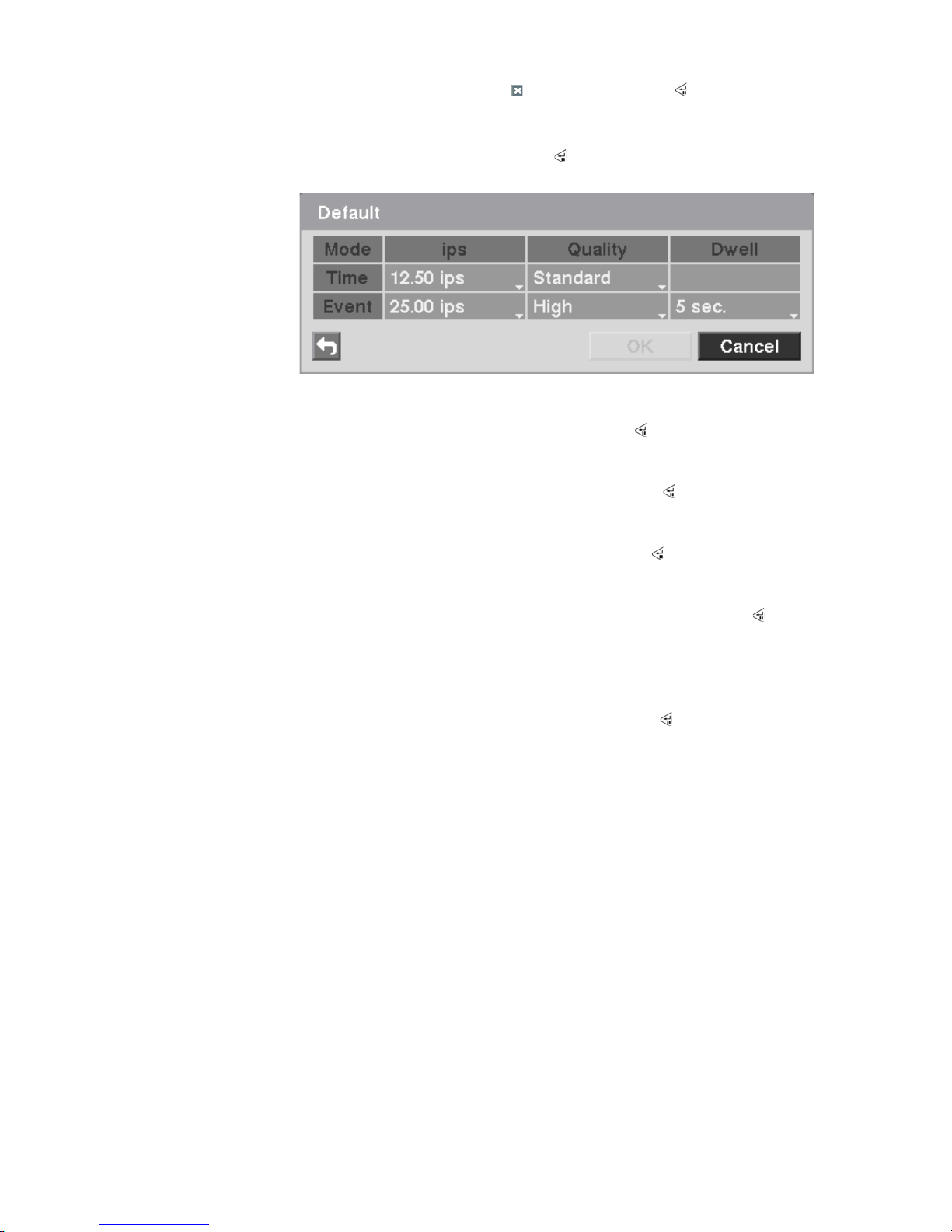
8. Highlight Default… and press the
button.
Î The Default screen appears.
Fig. 13 Default setup screen
Highlighting boxes under ips and pressing the
button allows you to set the
images per second for Time and Event recording. You can select from 0.10 to
25.0 (30.0 for NTSC) images per second.
Highlighting boxes under Quality and pressing the
button allows you to set
the recorded image quality for Time and Event recording. You can select from:
Very High, High, Standard and Basic.
Highlighting boxes under Dwell and pressing the
button allows you to set the
length of time you would like to record for the associated event (Advanced
Mode only).
Î You can save your changes by highlighting OK and pressing the button.
Î Selecting Cancel exits the screen without saving the changes.
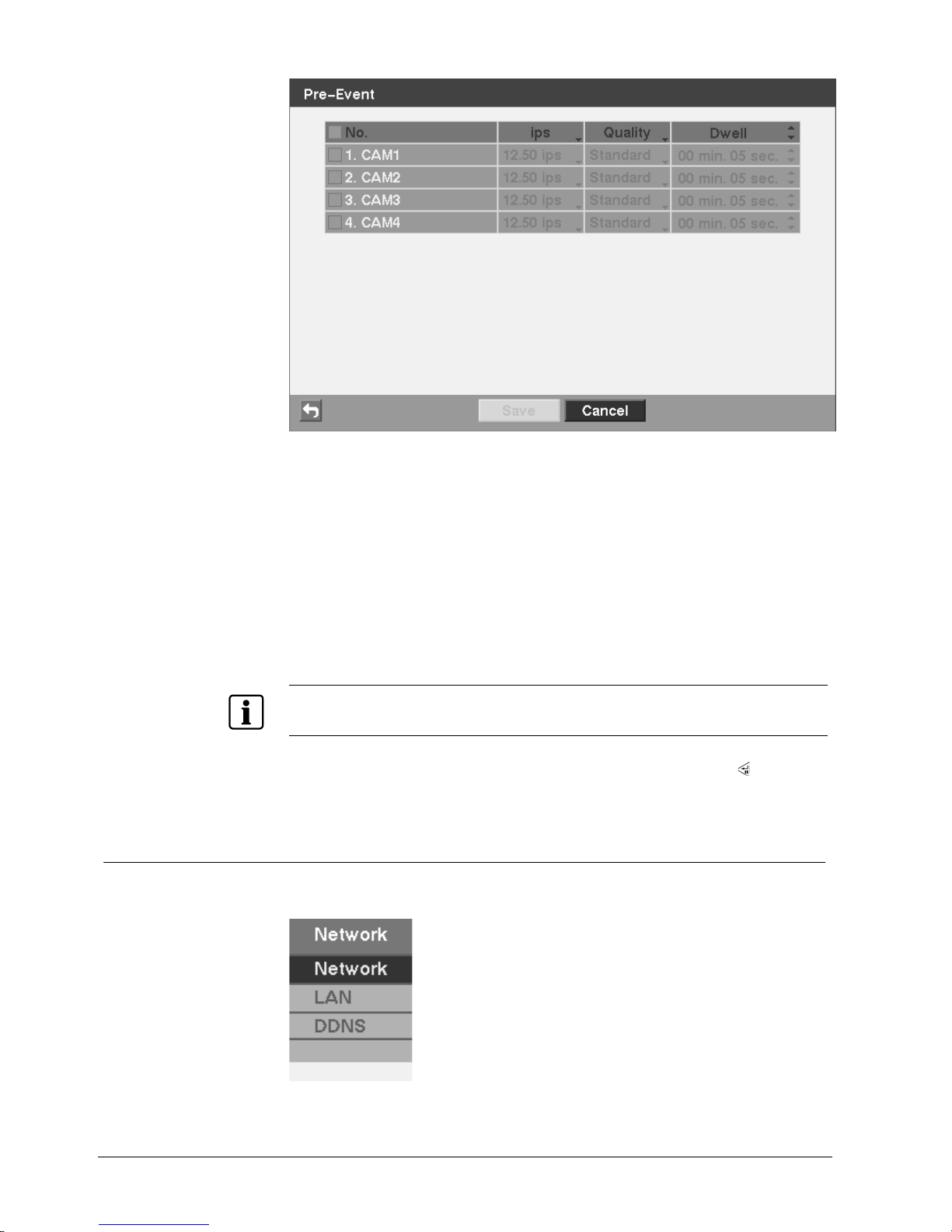
7.7.3 Pre-Event screen
Highlight Pre-Event in the Record menu and press the button.
Î The Pre-Event setup screen appears.
Î If you do not have Event set up in the Record Schedule, a message will display
alerting you to this fact.
Configuration
26
Siemens AG
06.2010
Fig. 14 Pre-Event setup screen
When the DVR is in the Event Record mode it is possible to have it record images
before the event occurs. The Pre-Event screen allows you to define how to handle
pre-event recording.
You can turn individual cameras On or Off for pre-event recording. The image speed
can be set from 0.10 to 25.00 ips (30.00 ips NTSC), and image quality can be
selected from Very High, High, Standard and Basic.
You can set the amount of time to record prior to the event by adjusting the dwell.
You can set the dwell from 5 seconds to 30 minutes. The longer the dwell set, the
fewer maximum ips can be set.
NOTE
When the DVR is in the Time or Time & Event mode, it ignores the pre-event settings and follows the
time settings.
Î You can save your changes by highlighting Save and pressing the button.
Î Selecting Cancel exits the screen without saving the changes.
7.8 Network setup
In the main screen, use the Left or Right arrow buttons to display the Network
menu.
Fig. 15 Network menu
Configuration
27
Siemens AG
06.2010
7.8.1 Network screen
Highlight Network in the Network menu and press the button.
Î The Network setup screen displays.
Î You will be able to change the Network, Mail, Callback and Web Client settings.
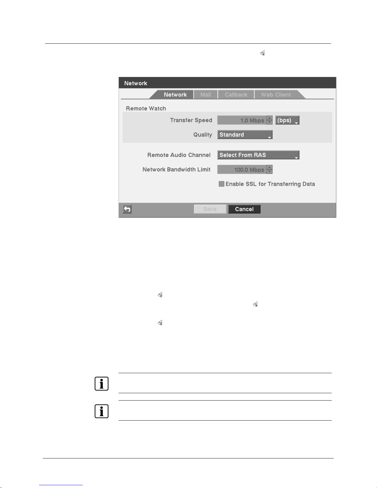
Fig. 16 Network setup screen
Network
1. Highlight the first box beside Transfer Speed.
2. Press the Up and Down arrow buttons to set the Transfer Speed from 50 Kbps
to 100 Mbps.
3. Highlight the second box beside Transfer Speed.
Î You can select the unit of measure for the transfer speed between: bps and ips.
4. Press the
button to set the transfer speed.
5. Highlight the box beside Quality and press the
button.
Î You can select the quality from: Very High, High, Standard and Basic.
6. Press the
button to set the Quality.
7. The DVR supports two-way audio communication between a local system and
a PC running RAS. Highlighting the box beside Remote Audio Channel and
pressing the button allows you to select a camera channel associated with the
audio channel that sends audio to the remote site. Selecting Select From RAS
will send audio of the channel selected from RAS.
NOTE
The higher Quality settings require higher Transfer Speed settings. The transfer speed you set is the
maximum speed. Depending on the network environment, this speed may not be achieved.
NOTE
The local recording speed might be affected by various network bandwidth (Transfer Speed)
conditions.
Configuration
28
Siemens AG
06.2010
NOTE
Depending on network conditions, audio might be interrupted or out of synchronization during
transmission.
NOTE
When limiting the network bandwidth, the remote watch image on the PC running RAS or Web Client
may not be displayed properly.
8. Highlight Enable SSL for Transferring Data and press the button to toggle
between On and Off. When it is On, the security of data except video and audio
transmitted for remote monitoring or remote recording can be enhanced by
using the SSL (Secure Sockets Layer) authentication. When using the SSL
function, the DVR cannot be connected with a remote program which does not
support the SSL function.
NOTE
The remote connection will be disconnected temporarily after changing the SSL settings.
NOTE
This product includes software developed by the OpenSSL Project for use in the OpenSSL Toolkit
(http://www.openssl.org).
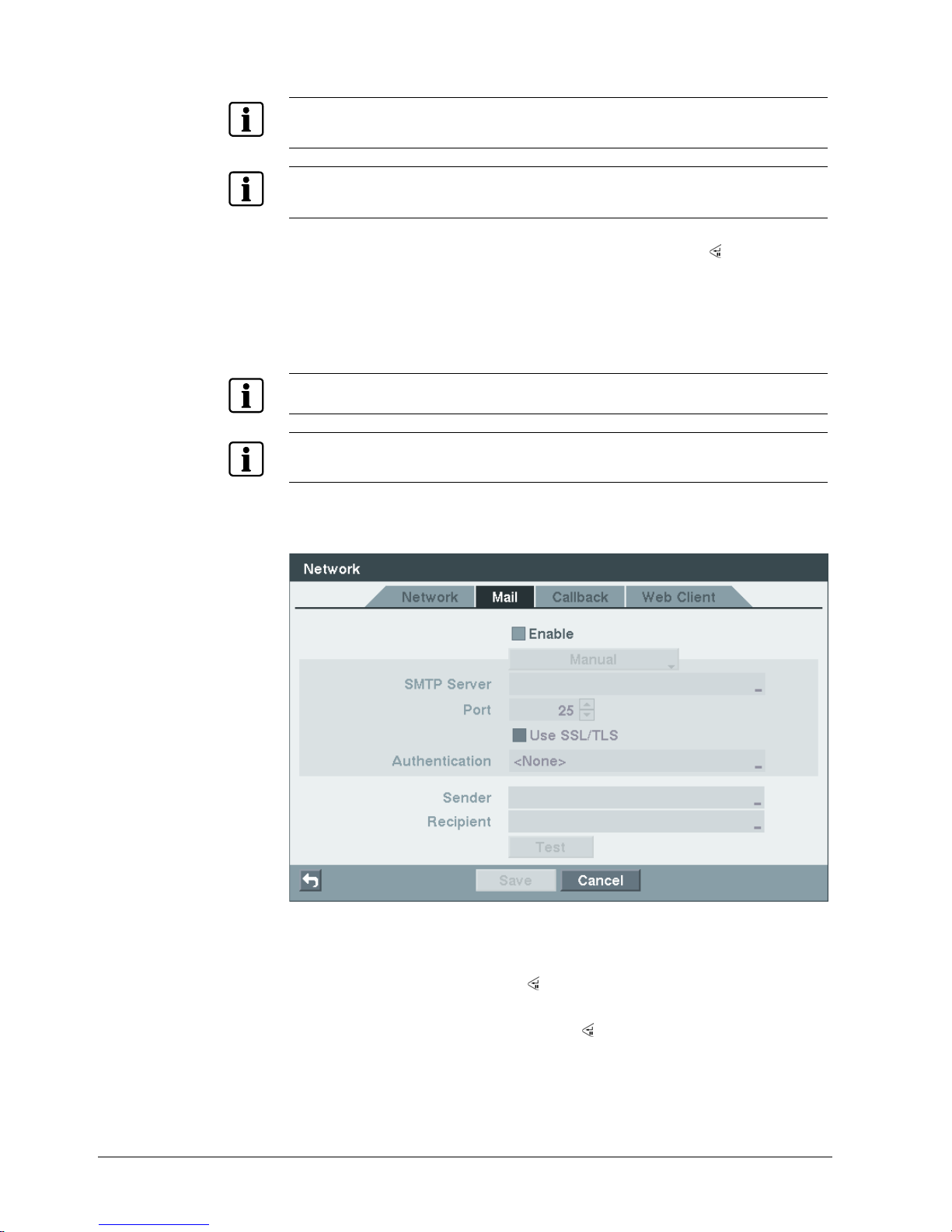
9. Highlight the Mail tab, and the Mail screen displays.
Î The DVR can be set up to send an email when an event occurs.
Fig. 17 Mail setup screen
Mail
1. Highlight Enable and press the
button to toggle between On and Off.
Î You will only be able to change the settings if Mail is enabled.
2. Highlight the Manual box and press the
button. A list of email service
provider appears. Selecting an email service provider from the list automatically
sets up the SMTP server, port and SSL/TLS usage settings. Selecting Manual
allows you to enter the settings manually
.
Configuration
29
Siemens AG
06.2010
3. Highlight the box beside SMTP Server and press the button.
Î A virtual keyboard appears that you can use to enter the IP address or domain
name of the SMTP server.
NOTE
You will need to get the IP Address or domain name of the SMTP Server from your network
administrator.
NOTE
You can use the domain name instead of IP address if you already set up the DNS Server when
setting up the LAN.
4. Use the arrow buttons to enter the SMTP Server IP address obtained from your
system administrator.
5. Highlight the box beside Port and press the
button.
6. Use the arrow buttons to enter the SMTP Server port number obtained from
your system administrator. The default port number is 25.
7. Highlight Use SSL/TLS and press the
button to toggle between On and Off.
Î When it is On, the DVR can send an email via an SMTP server requiring SSL
(Secure Sockets Layer) authentication.
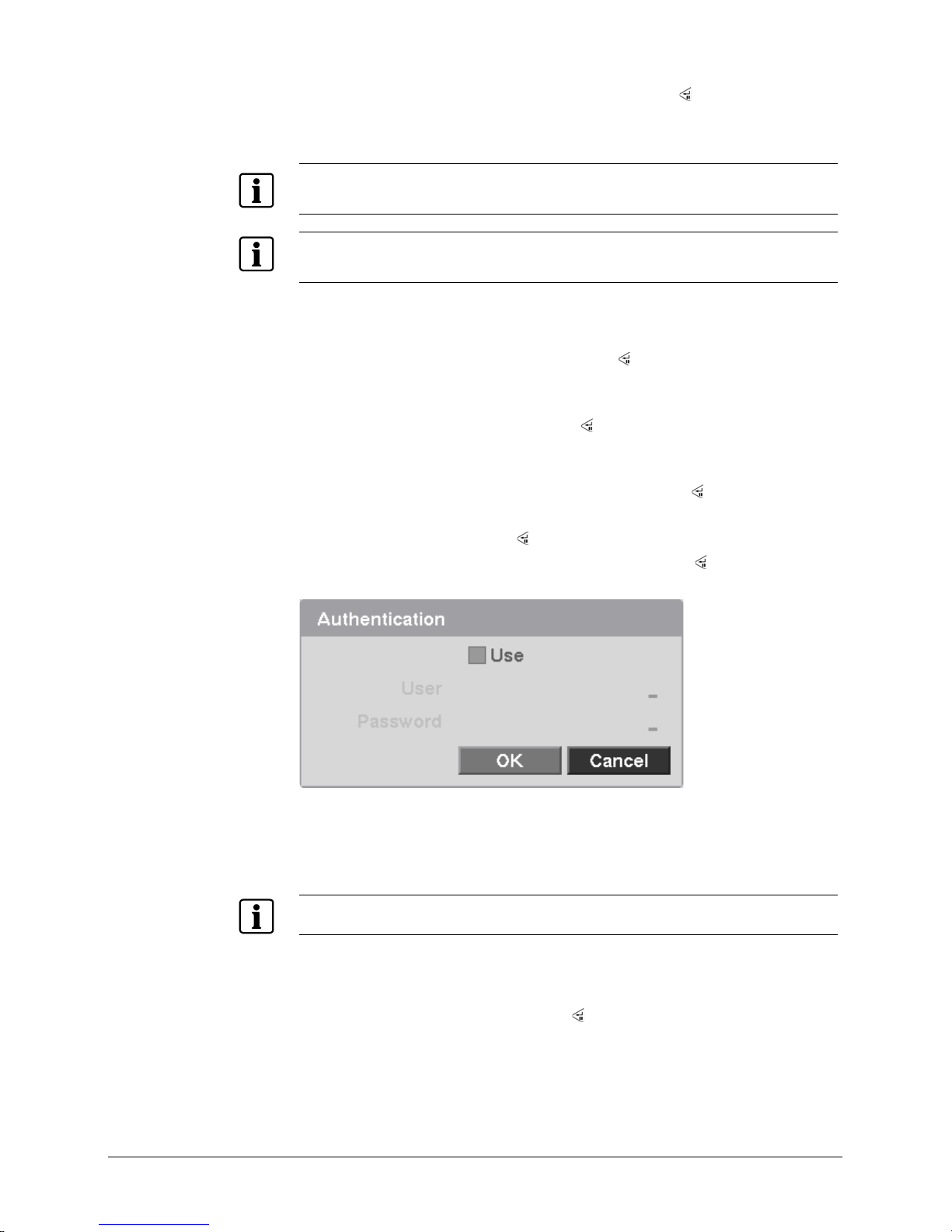
8. Highlight the box beside Authentication and press the
button.
Î An Authentication screen appears.
9. Highlight Use and press the
button to toggle between On and Off.
10. Highlight the box beside User/Password and press the
button.
Î A virtual keyboard appears allowing you to enter the user ID and password.
Fig. 18 Authentication setup screen
11. Highlight the box beside Sender and enter the sender’s e-mail address.
12. Use the virtual keyboard to enter the e-mail address.
NOTE
The e-mail address must include the “@” character to be a valid address.
13. Highlight the box beside Recipient and enter the recipient’s e-mail address.
14. Use the virtual keyboard to enter the e-mail address.
15. Highlight the Test box and press the
button to test emailing with the current
settings you made. Refer to 11.7 Error code notices for the description of SW
error code
s or the common SMTP response codes for the description of SMTP
response codes for the email test
.
Configuration
30
Siemens AG
06.2010
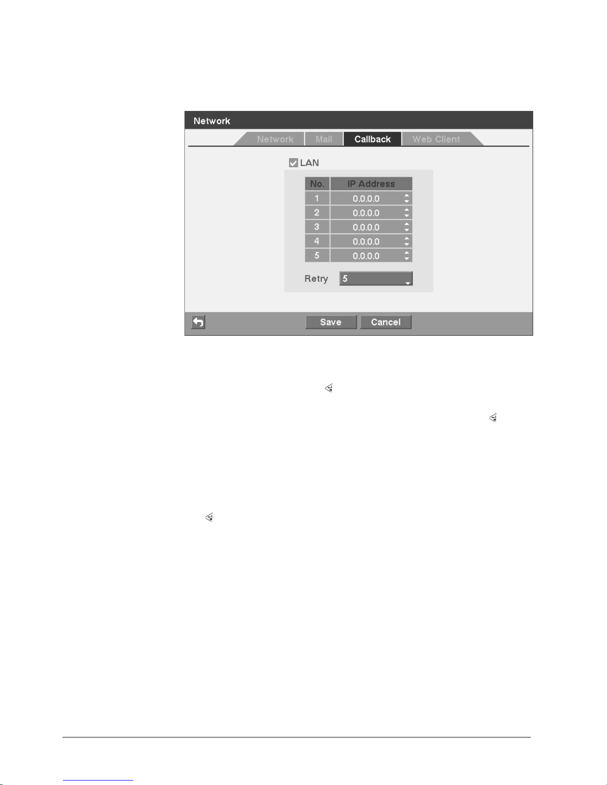
16. Highlight the Callback tab.
Î The Callback screen displays.
Î The DVR can be set up to contact a computer running RAS (Remote
Administration System) when an event occurs.
Fig. 19 Callback setup screen
Callback
1. Highlight LAN and press the
button to toggle between On and Off.
Î When LAN is turned On you can change the IP addresses.
2. Highlight the IP Address box that you want to change and press the
button.
3. Enter the IP address of the computer you want contacted during an event.
Î You can enter up to five IP addresses.
4. Highlight the box beside Retry and enter the number of times you would like
the DVR to try contacting the computer running RAS.
Î You can select from 1 to 10 retries.
5. You can save your notification changes by highlighting Save and pressing the
button.
Î Selecting Cancel exits the screen without saving the changes.
6. Highlight the Web Client tab.
Î The Web Client screen displays.
 Loading...