

Siemens SIROTEC, SIMODRIVE, SIMOTION, SINAMICS S120, SINUMERIK Planning Manual
Planning Guide 03/2004 Edition
EMC Installation Guideline
SINUMERIK, SIROTEC, SIMODRIVE
SIMOTION, SINAMICS S120


Introduction
1
EMC Basic Rules
2
Interference Spreading
3
Equipotential Bonding
4
Control Cabinet
Structure
5
Wiring and Shielding
6
Filtration
7
Troubleshooting and
Fault Elimination
8
Electrostatically
Sensitive Assemblies
(ESA)
9
EMC Law and CE
Mark
10
Health Protection
11
Index
I
EMC Installation Guideline
Planning Guide
Valid for
SINUMERIK
SIROTEC
SIMODRIVE
SIMOTION
SINAMICS S120
03.2004 Edition

Identification of the documentation
This book is part of the documentation on CD-ROM (DOCONCD)
Edition Order No. Remarks
03.04 6FC5298-7CA00-0BG0
C
Trademarks
SIMATIC®, SIMATIC HMI®, SIMATIC NET®, SIROTEC®, SINUMERIK® and SIMODRIVE® are registered
trademarks of Siemens AG. IBM® is a registered trademark of International Business Corporation. MS-DOS® and
WINDOWS
TM
are registered trademarks of Microsoft Corporation. Other product names used in this
documentation may be trademarks which, if used by third parties, could infringe the rights of their owners.
Printing history
Brief details of this edition and previous editions are listed below.
The status of each edition is shown by the code in the "Remarks" columns.
Status code in the "Remarks" column:
A .... New documentation.
B .... Unrevised reprint with new order no.
C .... Revised edition with new status.
Edition Order No. Remarks
12.98 6FC5297-0AD30-0BP0
A
06.99 6FC5297-0AD30-0BP1
C
03.04 6FC5297-0AD30-0BP2
C
Further information is available on the Internet under:
http://www.siemens.com/motioncontrol
This publicatio was produced with WinW ord V 8.0 and Designer V 7.0
and the DocuTool AutWinDoc.
The reproduction, transmission, or use of this document or its contents
is not permitted without express written authority. Offenders will be
liable for damages. All rights, including those created by patent grant or
registration or a utility model or design, are reserved.
© Siemens AG, 2004. All rights reserved
We have checked that the contents of this document corresponds to
the hardware and software described. Nonetheless, differences might
exist and therefore we cannot guarantee that they are completely
identical. The information contained in this documentation is, however,
reviewed regularly and any necessary changes will be included in the
next edition. We welcome suggestions for improvement.
Subject to change without prior notice
Order No. 6FC5297-0AD30-0BP2
Printed in Germany
Siemens Aktiengesellschaft

© Siemens AG, 2004. All rights reserved
EMC Installation Guideline – Planning Guide (EMV) – 03.2004 Edition
v
Preface
What does EMC mean
EMC is the abbreviation for electromagnetic compatibility. Electromagnetic
compatibility is defined as the characteristic of a piece of electrical equipment to
function satisfactory in a predetermined electromagnetic environment without
influencing this environment unduly.
Who is this manual for
· Project managers creating NC and drive system configurations.
· Installers routing the connection lines.
· Service engineers involved in troubleshooting and fault elimination.
Machine manufacturers
The notes indicated in Chapters 2, 4, 5, 6, 7, 9, 10, 11 are primarily directed
towards machine manufacturers, who can influence or change the functional
behaviour of the complete system by means of the described measures.
Subject matter of this manual
You receive the following information in this Guideline:
· Why are EMC guidelines necessary?
· Which interference sizes have an effect on the control from outside
(interference sink)?
· How can EMC malfunctions be prevented?
· Which practical application examples are available for a trouble-free system
structure?
· What must be considered when handling electrostatically sensitive
assemblies?
· How can a malfunction caused by a deficient EMC be eliminated?
Objectives
These guidelines are not, and do not aim to be, a textbook for EMC. The purpose
of these guidelines is to provide the practical person with instructions for securing
the EMC.
Compliance with these EMC guidelines are necessary to
a) achieve a minimum noise immunity of the accessories in such a way that they
function perfectly in a harsh industrial environment and
b) to not have an undue impact on the environment in terms of radio interference.

Preface
© Siemens AG, 2004. All rights reserved
vi EMC Installation Guideline – Planning Guide (EMV) – 03.2004 Edition
These guidelines also describe the necessary measures according to the
European Union (EU) directives for compliance with the EMC law or the EMC
guidelines.
In installation locations with extremely high interference levels, malfunctions can be
caused despite compliance with these EMC Guidelines, although it is very unlikely.
What prior knowledge is required?
Apart from these EMC Guidelines, international and country-specific safety
regulations continue to apply.
Good knowledge of the relevant standards and EU regulations is necessary, so
that the safety concerns are not impaired when implementing these EMC
Guidelines. The implementation of these EMC Guidelines must be performed by
qualified personnel.
Qualified personnel
All persons who are entrusted with the installation, assembly, commissioning and
operation of the product and who possess the necessary qualifications are to be
considered to be qualified personnel.
The authorization to connect circuits and devices in accordance with the approved
standards of electrical engineering, to bring them into operation and to remove
them from operation applies as a particular qualification.
Hotline
If you have any questions, please get in touch via our hotline:
A&D Technical Support Phone.: ++49-(0)180-5050-222
Fax: ++49-(0)180-5050-223
Email: adsupport@siemens.com
If you have any questions about the documentation (suggestions, corrections, etc.),
please send a fax or e-mail to:
Fax: ++49-(0)9131-98-2176
Email: motioncontrol.docu@erlf.siemens.de
Fax form: See the reply form at the end of the document.
Internet addresses
Motion Control Systems: http://www.siemens.com/motioncontrol
Finding your way around
To assist you in your orientation, you have a table of contents and an index.

Preface
© Siemens AG, 2004. All rights reserved
EMC Installation Guideline – Planning Guide (EMV) – 03.2004 Edition
vii
Safety and warning concept
The following safety and warning information is used in this document.
Explanation of symbols used:
!
Danger
Indicates an imminently hazardous situation which, if not avoided, will
result in
death or serious injury or in substantial property damage.
!
Warning
Indicates a potentially hazardous situation which, if not avoided, could
result in
death or serious injury or in substantial property damage.
!
Caution
This symbol (with a warning triangle) indicates that minor injury or damage to
property may
result if proper precautions are not taken.
Caution
Used without safety alert symbol indicates a potentially hazardous situation
which, if not avoided, may
result in property damage.
Notice
Used without the safety alert symbol indicates a potential situation which, if not
avoided, may
result in an undesirable result or state.

Preface
© Siemens AG, 2004. All rights reserved
viii EMC Installation Guideline – Planning Guide (EMV) – 03.2004 Edition
Other information
!
Important
Important indicates an important or especially relevant item of information.
Note
Note refers to an important item of information about the product, handling of
the product or part of the documentation which is particularly relevant in the
current context.
Machine manufacturer
This symbol appears in this documentation whenever the machine manufacturer
can influence or modify the described functional behavior. Please observe
the information provided by the machine manufacturer!
n

© Siemens AG, 2004. All rights reserved
EMC Installation Guideline – Planning Guide (EMV) – 03.2004 Edition
ix
Contents
1 Introduction ..................................................................................... 1-11
2 EMC Basic Rules............................................................................. 2-13
3 Interference Spreading................................................................... 3-15
3.1 Interference sources ..................................................................... 3-16
3.2 Interference sinks.......................................................................... 3-16
3.3 Coupling paths .............................................................................. 3-17
4 Equipotential Bonding.................................................................... 4-19
4.1 Equipotential bonding in built-in cabinets...................................... 4-20
4.2 Equipotential bonding of external components ............................. 4-22
4.3 Examples of equipotential bonding ............................................... 4-25
5 Control Cabinet Structure .............................................................. 5-29
5.1 Design and assembly of the cabinet ............................................. 5-29
5.1.1 Earthing of control cabinet components .................................... 5-29
5.1.2 Breakdowns in the control cabinet wall...................................... 5-29
5.2 Assembly of the components in the control cabinet...................... 5-31
5.3 Wiring, shielding and earthing....................................................... 5-33
6 Wiring and Shielding ...................................................................... 6-35
6.1 Cable running................................................................................ 6-35
6.2 Shielding ....................................................................................... 6-37
6.2.1 Introduction ................................................................................ 6-37
6.2.2 Basic rules for the shield connection of simple shielded lines... 6-38
6.2.3 Shielding measures with power lines......................................... 6-40
6.2.4 Further conduction of the line shield at the interruption point .... 6-41
6.2.5 Example of shield connections .................................................. 6-42
7 Filtration........................................................................................... 7-45
7.1 Interference suppression of inductors........................................... 7-45
7.2 Filter .............................................................................................. 7-46
8 Troubleshooting and Fault Elimination ........................................ 8-49
8.1 Troubleshooting ............................................................................ 8-49
8.2 Fault clearance.............................................................................. 8-49

Contents
© Siemens AG, 2004. All rights reserved
x EMC Installation Guideline – Planning Guide (EMV) – 03.2004 Edition
9 Electrostatically Sensitive Assemblies (ESA) .............................. 9-51
9.1 What does ESD mean? ................................................................ 9-51
9.2 Electrostatic charging of objects and people ................................ 9-52
9.3 Packing and dispatch of electrostatically sensitive assemblies .... 9-52
9.4 Basic protective measures against static electricity discharges ... 9-53
10 EMC Law and CE Mark ................................................................. 10-55
10.1 Notes on the EMC rule................................................................ 10-55
10.2 Notes for machine manufacturers............................................... 10-56
10.3 CE mark/EU declaration of conformity........................................ 10-56
11 Health Protection .......................................................................... 11-59
I Index.................................................................................................. I-61
© Siemens AG, 2004. All rights reserved
EMC Installation Guideline – Planning Guide (EMV) – 03.2004 Edition
1-11
1 Introduction
To attain the electromagnetic compatibility (EMC) requested in the EMC Guideline
of a complete plant (control and drive engine), EMC measures on the part of the
control manufacturer and user (including machine tool manufacturer) are required.
Concerning
manufacturer
EMC compatible
design
(electrically and
mechanically)
Concerning
user
EMC compatible
installation
(in the room with
cabling)
EMC compatible total system
Fig. 1-1 Securing the EMC
!
Important
To secure the EMC, you must pay attention to the:
· product-specific EMC measures contained in
the EMC Guidelines,
· to project or operate only permitted combinations and
· to use the accessories provided in the product-specific documentation
(e.g. ready-made wiring) or equivalent.
n

Introduction
© Siemens AG, 2004. All rights reserved
1-12 EMC Installation Guideline – Planning Guide (EMV) – 03.2004 Edition
Notes

© Siemens AG, 2004. All rights reserved
EMC Installation Guideline – Planning Guide (EMV) – 03.2004 Edition
2-13
2 EMC Basic Rules
Mass of metal parts
· Connect all metal parts of the control cabinet flat and well-conducting with each
other.
· Connect the cabinet doors via short ground straps (upper, middle, lower) with
the cabinet beam.
· Connect the shield bus and potential compensation bus extensively with the
cabinet housing.
· Create permanent connections of the metal parts. Perform screw connections
on painted and anodized metal parts either by means of special contact discs
or permanently remove the insulating protective layer between the parts.
· Do not use any aluminium parts if possible (danger of oxidation).
Filter
· Filter must usually be mounted directly at the place where the line to be filtered
enters the cabinet.
· Specific filters such as e.g. the SIMODRIVE filter module or the STEPDRIVE
filter must be placed, mounted and connected according to the manufacturers’
documentation.
· Filters must be fastened in such a way that they lie flat and have a good,
durable, conductive connection to the cabinet housing (assembly plate).
· The lines running to the filters must be separated from the lines exiting the
filters. Filtered lines must be run separately from unfiltered lines.
Cable running
· Route the signal-/data lines spatially separated from the power current-/power
supply lines (avoid coupling routes). Minimum distance in the control cabinet:
20 cm. Use an earthed separating plate, if necessary.
· Twist unshielded lines of the same circuit (forward and return conductor) if
possible or minimize the distance between the forward and return conductor.
· Route the lines as close as possible to metallic housing parts (e.g. assembly
plate, supporting beams, metal rails).
· Route signal lines and the appropriate potential compensation line as close as
possible to each another.
· Never route signal lines on devices which produce strong magnetic fields. (e.g.
motors, transformers).
· If possible, insert the signal/data lines at only one level (e.g. only from below)
into the cabinet.

EMC Basic Rules
© Siemens AG, 2004. All rights reserved
2-14 EMC Installation Guideline – Planning Guide (EMV) – 03.2004 Edition
· Avoid unnecessary line lengths (also with spare lines).
· Signal lines in particular nominal and actual value lines should be routed
without breaks. Ensure continuous shielding at the dividing points.
Fastening the line shields
· Earth the shields of the data lines, analog signal lines and power lines on both
sides extensively and well conducting.
· Line shields should be inserted directly after the entry of the line into the
cabinet onto a shield bus and routed up to the component. The shield contact
is ensured by screwing the plug to the component housing via the productspecific, ready-made lines.
· Only metallic or metallized plug housings must be used for shielded lines.
Remedy of possible interference sources
· The coils of contactors, relays, solenoid valves and other inductors in the
cabinet, also perhaps in adjacent environment must be wired. Wiring is
performed, for example with RC elements, varistors, etc., directly on the
respective coil.
· Use light bulbs as possible for the lighting of cabinets. Avoid the use of
fluorescent lamps.
Uniform system reference potential
· If system components are housed in different cabinets, then they must be
connected via e.g. an equipotential bonding conductor.
· Adequately-sized equipotential bonding lines must be used against potential
differences between system parts.
Measures against the effects of lightning strikes
Measures must be taken in buildings, rooms and electrical devices for the
protection of the electrical appliances against overvoltage, caused by lightning
strikes. Therefore we recommend you to contact your Siemens office or the
relevant specialist firms.
Handling of components susceptible to electrostatic damage
· Wear an electrostatic wristband when working with components susceptible to
suffering damage due to electrostatic discharge.
· Use storage surfaces suitable for electrostatically damageable components
and packaging made of electrostatically safe materials, e.g. uncoated
cardboard boxes.
· See also Chapter 9.
n

© Siemens AG, 2004. All rights reserved
EMC Installation Guideline – Planning Guide (EMV) – 03.2004 Edition
3-15
3 Interference Spreading
Electromagnetic interference sizes have only an effect on a control or system when
the following three components are available:
• Interference source
• Coupling path
• Interference sink
Source of interference
(interfering object)
Potentially susceptible
equipment
(interfered device)
e.g. drive unit, motor,
inductivity
Data link
e.g. setpoint cabel
e.g. positioning control,
numerical control
Fig. 3-1 Electromagnetic environment

Interference Spreading
© Siemens AG, 2004. All rights reserved
3-16 EMC Installation Guideline – Planning Guide (EMV) – 03.2004 Edition
3.1 Interference sources
The initiator of the interference is described as the interference source. The noise
levels generated by the interference sources or their effects must be eliminated or
at least dampened by appropriate measures.
Table 3-1 Typical interference sources and their effects on interference sinks
Interference source
Interference generated
by…
Effect
Switched inductors such as e.g.
contactors, relays, electronic valves
- Contacts
- Coils
- System disturbances
- Electromagnetic fields
- Magnetic fields
Electrical motors - Collectors
- Coils
- Electromagnetic fields
- Magnetic fields
Sparking machines such as
e. g. electrical welding equipment,
electrical discharge machines
- Contacts
- Transformers
- Electromagnetic fields
- System disturbances
- Compensating currents
- Magnetic fields
Power supply units - Circuits
- Switching components
- Electromagnetic fields
- System disturbances
High-frequency appliances - Circuits - Electromagnetic fields
Transmitters - Antennas - Electromagnetic fields
Earth or reference potential
differences
- Voltage differences - Compensating currents
Operator - Discharges of static
electricity
- Electrical discharge currents
- Electrical fields
Power lines - Current flows
- Fuse cases
- Power break-ins, power
overvoltages
- Electrical and magnetic fields
Transmission lines - Voltage differences
- Corona discharges
- Electromagnetic fields
- Electrical fields
Current converters, power electronics - Circuits - Overvoltages
- Compensating currents
3.2 Interference sinks
An interference sink is an electrical device, whose function can be influenced by
interference sizes.
Table 3-2 Typical interference sinks and their reaction on interferences
Interference sinks are sensitive against… Reaction
Microprocessor-controlled
systems, bus systems
Pulse-shaped noise levels (e.g.
switching operations) and
electromagnetic fields
Sporadic processor shutdown,
transmission errors
Analog circuits Low-frequency noise levels (e.g.
potential differences)
Superimposition of the effective signal
on the noise level (e.g. 50 Hz hum on
setpoint)
Electron beam monitors low-frequency magnetic fields
(> 1.5 A/m)
Flickering screen or image, colour
distortion
Telephones Mains second harmonics Whistling is audible
Fax machines, power
supply units
Mains second harmonics Fuse case or defect in the power supply
unit, whistling is audible
Interference Spreading
© Siemens AG, 2004. All rights reserved
EMC Installation Guideline – Planning Guide (EMV) – 03.2004 Edition
3-17
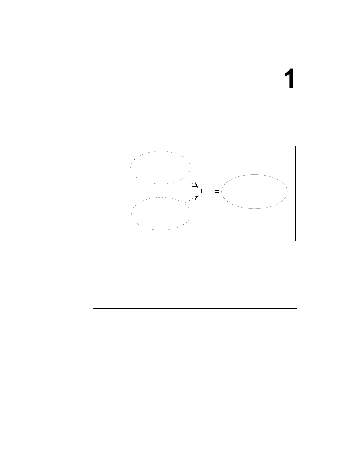
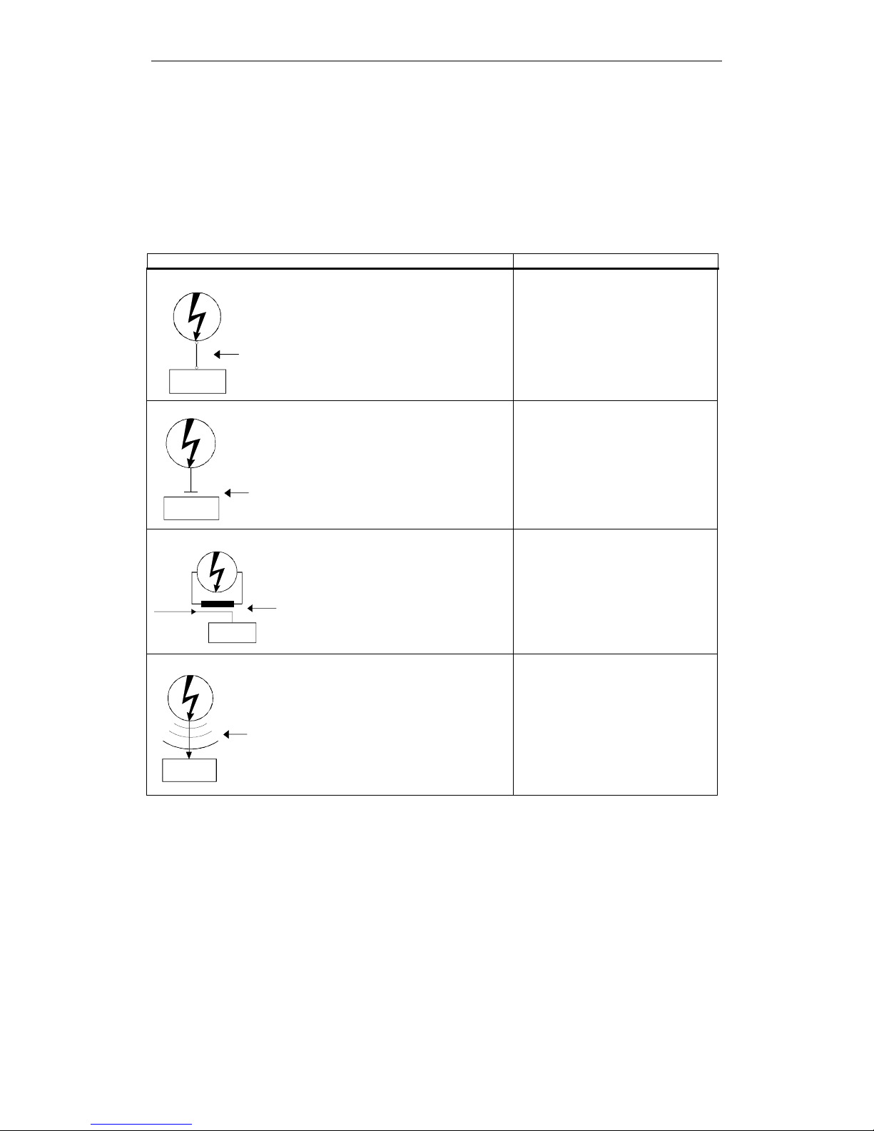
3.3 Coupling paths
The coupling path is the transmission path for the noise levels generated by an
interference source. Through them, the noise levels can spread from the
interference source to the interference sink. Different coupling mechanisms exist
for the interference coupling:
Table 3-3 Coupling mechanisms and their typical interference sources
Coupling mechanism Interference sources
Galvanic coupling
Interferenc e
source
Conductive
coupling path
Interference
sinks
Galvanic or metallic coupling
always occurs when two circuits
jointly use a conductor (e.g.
joint earth line).
• Cycled appliances (mains
influence by converter and
external power supply units)
• Starting motors
• Different potential of component
housings with common power
supply
Capacitive coupling
Interference
source
Capacitive
coupling path
Interference
sink
Capacitive or electrical coupling
occurs between mutually
insulated conductors which are
on a different potential.
• Interference coupling by parallel
running line
• Static discharge of the operator
• Contactors
Inductive coupling
Interference
Inductive
coupling
path
Interference
sink
Useful
signal
source
Inductive or magnetic coupling
occurs between conductor
loops of those at least one is
live. The magnetic flows linked
with the currents induce
interference voltages.
• Transformers, motors, electrical
welding equipment
• Parallel running power line
• Lines with switched currents
• Signal line with high frequency
• Non-switched solenoids
Radiation coupling
Interference
source
Radiated
coupling path
Interference
sink
Radiation coupling is present if
an electromagnetic wave hits a
line formation. The hit of the
electromagnetic wave induces
currents and voltages.
• Adjacent transmitter (e.g. walkie-
talkies)
• Spark paths (spark plugs,
collectors of electric motors,
welding equipment)

Interference Spreading
© Siemens AG, 2004. All rights reserved
3-18 EMC Installation Guideline – Planning Guide (EMV) – 03.2004 Edition
Table 3-4 Examples for coupling paths
Coupling path Cause
Lines
• Incorrect or inappropriate laying
• Missing or incorrectly connected shield
• Inappropriate spatial arrangement of the lines (incl. equipotential
bonding line)
• Unsuitable lines
Control cabinet or housing of the
controls
• Missing or incorrectly wired compensation line
• Missing or incorrect earthing
• Inappropriate spatial arrangement
• Components not mounted securely
• Unfavourable cabinet structure
n

© Siemens AG, 2004. All rights reserved
EMC Installation Guideline – Planning Guide (EMV) – 03.2004 Edition
4-19
4 Equipotential Bonding
Note
Equipotential bonding must not be confused with protection against electric shock
by means of a protective line system. This protective measure must be performed
according to the appropriate standards and guidelines and is not a constituent
part of these EMC Guidelines.
Why is equipotential bonding necessary?
Basic principle:
Control components between which a signal connection exists also require a
potential connection. System malfunctions of the electrical components are
prevented by equipotential bonding between the electrical components among
each other and the earth.
Where is equipotential bonding required?
a) Between all control components which are also interconnected to each other
via signals.
b) Between control components and the central earthing bar.
Note
The central earthing bar is a bus bar for all earth, equipotential bonding and
protective conductors of a control cabinet. The external protective conductor or
the building earthing system is also connected to this bus.
Exception:
A potential connection is not necessary for control components with potential-free
signal transmission (e. g. via light wave conductor), in many cases it is also not
permissible.
No direct potential connection line is required (applicable to all digital signal
transmissions between the central appliance and the cabinet external components)
for control components, for which the signal transmission is conditionally potentialfree, i.e. it is only potential-free up to a certain voltage level. Here a short potential
connection to the respective earth (reference potential) is sufficient.

Equipotential Bonding
© Siemens AG, 2004. All rights reserved
4-20 EMC Installation Guideline – Planning Guide (EMV) – 03.2004 Edition
4.1 Equipotential bonding in built-in cabinets
Equipotential bonding via meshing
The equipotential bonding between the individual control components among each
other and the central earthing bar within a metallic housing (cabinet) should
preferably be performed by meshing.
Meshing is understood to mean the conducting connection of several components,
whereby a direct conducting connection exists between all components. (See
Section 4.2, Fig. 4-1).
Points to bear in mind:
• Components with metal housings must be bolted onto the cabinet housing
(assembly plate). Ensure an large-surface conducting connection.
Note
This direct galvanized connection of the metal housing to the cabinet rear via the
component fastening bolts is only possible if the terminal at the control
components (designation:
or ) for the equipotential bonding line has a
large-surface galvanic connection with the fastening bearing surface of the
components.
In the event that the control components have an insulated housing fastening or
the fastening facing consists of metallized (galvanized) plastics, the connection
between the equipotential bonding terminal of the component and the cabinet
housing must be provided ≥ via a short equipotential bonding line 10 mm
2
Cu
(see Section 4.2 Fig. 4-1, component 3).
• The connection between the central earthing bar and the cabinet housing must
be low-resistance, short and with a large surface area.
• All contact surfaces for earth connections must be metallically bare. It is
absolutely essential to remove the oxide and colour coat permanently.
• The corrosion resistance of the earth connections must be ensured, particularly
in respect of contact corrosion and resistance against external influences.
 Loading...