

Siemens SIRIUS PROFINET,SIRIUS 3RW44 User Manual
Industrial Controls
SIRIUS
PROFINET Communication Module for SIRIUS Soft Starter 3RW44
GerätehandbuchManual
Edition
Answers for industry.
12/2013


PROFINET Communication Module for
SIRIUS Soft Starter 3RW44
___________________
___________________
___________________
___________________
___________________
___________________
___________________
___________________
Industrial Controls
SIRIUS
PROFINET Communication Module
for SIRIUS Soft Starter 3RW44
Manual
12/2013
Introduction
1
Safety information
2
Product description
3
Installation / removal
4
Configuring/assigning
parameters
5
Commissioning
6
Functions
7
Technical specifications
8
Dimension drawings
9
Circuit diagram example
10
Appendix
A
___________________
___________________
___________________
A5E31996495002A/RS-AA/001
Warning notice system
DANGER
will
WARNING
may
CAUTION
NOTICE
Qualified Personnel
personnel qualified
Proper use of Siemens products
WARNING
maintenance are required to ensure that the products operate safely and without any problems. The permissible
Trademarks
Disclaimer of Liability
Legal information
This manual contains notices you have to observe in order to ensure your personal safety, as well as to prevent
damage to property. The notices referring to your personal safety are highlighted in the manual by a safety alert
symbol, notices referring only to property damage have no safety alert symbol. These notices shown below are
graded according to the degree of danger.
indicates that death or severe personal injury
indicates that death or severe personal injury
indicates that minor personal injury can result if proper precautions are not taken.
indicates that property damage can result if proper precautions are not taken.
If more than one degree of danger is present, the warning notice representing the highest degree of danger will
be used. A notice warning of injury to persons with a safety alert symbol may also include a warning relating to
property damage.
The product/system described in this documentation may be operated only by
task in accordance with the relevant documentation, in particular its warning notices and safety instructions.
Qualified personnel are those who, based on their training and experience, are capable of identifying risks and
avoiding potential hazards when working with these products/systems.
result if proper precautions are not taken.
result if proper precautions are not taken.
for the specific
Note the following:
Siemens products may only be used for the applications described in the catalog and in the relevant technical
documentation. If products and components from other manufacturers are used, these must be recommended
or approved by Siemens. Proper transport, storage, installation, assembly, commissioning, operation and
ambient conditions must be complied with. The information in the relevant documentation must be observed.
All names identified by ® are registered trademarks of Siemens AG. The remaining trademarks in this publication
may be trademarks whose use by third parties for their own purposes could violate the rights of the owner.
We have reviewed the contents of this publication to ensure consistency with the hardware and software
described. Since variance cannot be precluded entirely, we cannot guarantee full consistency. However, the
information in this publication is reviewed regularly and any necessary corrections are included in subsequent
editions.
Siemens AG
Industry Sector
Postfach 48 48
90026 NÜRNBERG
GERMANY
3ZX1012-0RW40-0AC0
Ⓟ 12/2013 Technical data subject to change
Copyright © Siemens AG 2013.
All rights reserved

Table of Contents
1 Introduction................................................................................................................................... 9
2 Safety information ....................................................................................................................... 13
3 Product description ...................................................................................................................... 17
4 Installation / removal .................................................................................................................... 23
5 Configuring/assigning parameters ................................................................................................. 27
6 Commissioning ........................................................................................................................... 31
7 Functions ................................................................................................................................... 43
1.1 Important notes ........................................................................................................................ 9
2.1 Security information ................................................................................................................ 13
2.2 Before commencing work: Isolating the equipment from the supply system and ensuring
that it cannot be reconnected.................................................................................................. 13
2.3 Data security in automation .................................................................................................... 14
3.1 Fieldbus interfaces ................................................................................................................. 18
3.1.1 PROFINET IO ........................................................................................................................ 18
3.2 Communication principle ........................................................................................................ 20
3.3 Display when PROFINET communication module is activated ................................................ 21
3.4 Fieldbus for PROFINET menu structure.................................................................................. 22
4.1 Inserting the PROFINET communication module .................................................................... 23
4.2 Ethernet cable to RJ45 socket ................................................................................................ 25
4.3 Removal of the PROFINET communication module ................................................................ 25
5.1 Configuring soft starters ......................................................................................................... 27
5.1.1 Configuring with a GSD file ..................................................................................................... 27
5.1.2 Assigning parameters with the "Soft Starter ES 2007" software .............................................. 27
5.1.3 Diagnostics package .............................................................................................................. 28
5.2 Configuring the properties of 3RW44 PN as IO device ............................................................ 28
6.1 Activation of the PROFINET communication module via the display ....................................... 31
6.1.1 Activation of the fieldbus interface .......................................................................................... 32
6.1.2 Saving settings retentively ...................................................................................................... 33
6.2 Activation of the PROFINET communication module via software ........................................... 34
6.3 Parameter settings in the soft starter under Fieldbus .............................................................. 36
7.1 PROFIenergy ......................................................................................................................... 43
7.1.1 Energy saving function command ........................................................................................... 44
7.1.2 Measured value function command ........................................................................................ 46
7.1.3 Function blocks for SIMATIC S7 ............................................................................................. 46
PROFINET Communication Module for SIRIUS Soft Starter 3RW44
Manual, 12/2013, A5E31996495002A/RS-AA/001
5

Table of Contents
8 Technical specifications ............................................................................................................... 67
9 Dimension drawings .................................................................................................................... 69
10 Circuit diagram example .............................................................................................................. 73
A Appendix ................................................................................................................................... 75
7.2 OPC UA server .......................................................................................................................47
7.2.1 Features of OPC UA ...............................................................................................................47
7.2.2 Reading and writing data .........................................................................................................48
7.2.3 Activating the OPC UA server .................................................................................................48
7.2.4 Setting the IP parameters ........................................................................................................49
7.2.5 Access to the OPC UA server .................................................................................................50
7.2.6 Establishing a connection to the OPC UA server .....................................................................52
7.2.7 Connection monitoring ............................................................................................................53
7.3 Web server .............................................................................................................................54
7.3.1 Contents of web pages ............................................................................................................54
7.3.2 Activating the web server ........................................................................................................54
7.3.3 Setting the IP parameters ........................................................................................................55
7.3.4 Access to the web server ........................................................................................................56
7.3.5 Establishing a connection to the web server ............................................................................56
7.4 Time synchronization ..............................................................................................................57
7.5 SNMP .....................................................................................................................................58
7.6 Diagnostic functions ................................................................................................................59
7.6.1 Diagnostics of the communication module via LED display ......................................................59
7.6.2 Diagnostics with STEP 7 .........................................................................................................60
7.6.2.1 Evaluation of interrupts with PROFINET IO .............................................................................60
7.6.2.2 Error types ..............................................................................................................................61
7.6.3 Diagnostics and alarms ...........................................................................................................62
7.7 Firmware update of the PROFINET communication module ....................................................63
7.8 Factory settings .......................................................................................................................65
8.1 Conditions for storage and operation .......................................................................................67
8.2 Standards and approvals .........................................................................................................67
9.1 PROFINET communication module .........................................................................................69
9.2 PROFINET communication module with connectors ................................................................70
A.1 Data formats and data records ................................................................................................75
A.1.1 Process data and process images ...........................................................................................75
A.1.2 Data record 68 - Read/write process image of the outputs (PIO) ..............................................80
A.1.3 Data record 69 - Process image of the inputs (PII) ...................................................................82
A.1.4 Data record 72 - Log list - Read device error ...........................................................................83
A.1.5 Data record 73 - Log list - Read trips .......................................................................................84
A.1.6 Data record 75 - Log list - Read events....................................................................................85
A.1.7 Data record 81 - Read basic setting of data record 131 ...........................................................86
A.1.8 Data record 82 - Read basic setting of data record 132 ...........................................................86
A.1.9 Data record 83 - Read basic setting of data record 133 ...........................................................87
A.1.10 Data record 92 - Read device diagnostics................................................................................87
A.1.11 Data record 93 - Write commands ...........................................................................................93
A.1.12 Data record 94 - Read measured values .................................................................................94
PROFINET Communication Module for SIRIUS Soft Starter 3RW44
6 Manual, 12/2013, A5E31996495002A/RS-AA/001

Table of Contents
Glossary ................................................................................................................................... 115
Index ....................................................................................................................................... 119
A.1.13 Data record 95 - Read statistical data ..................................................................................... 95
A.1.14 Data record 96 - Read maximum pointer ................................................................................ 96
A.1.15 Data records 131, 141, 151 - Technology parameter 2: Read/write record 1, 2, 3.................... 97
A.1.16 Data records 132, 142, 152 - Technology parameter 3: Read/write record 1, 2, 3.................. 102
A.1.17 Data record 133 - Technology parameter 4: OCM module .................................................... 102
A.1.18 Data record 165 - Read/write comment ................................................................................ 103
A.1.19 OPC UA variables ................................................................................................................ 104
A.2 List of abbreviations ............................................................................................................. 110
A.3 Correction sheet ................................................................................................................... 113
PROFINET Communication Module for SIRIUS Soft Starter 3RW44
Manual, 12/2013, A5E31996495002A/RS-AA/001
7

Table of Contents
PROFINET Communication Module for SIRIUS Soft Starter 3RW44
8 Manual, 12/2013, A5E31996495002A/RS-AA/001

1
1.1
Important notes
Purpose of this manual
Target group
Required basic knowledge
Scope
This manual contains the basics for using SIRIUS 3RW44 soft starters in conjunction with
the PROFINET communication module. The soft starter can be optionally expanded to
include a PROFIBUS or PROFINET communication module. The PROFINET communication
module allows a 3RW44 soft starter to be connected to the PROFINET communication
system.
The SIRIUS 3RW44 soft starter is an electronic motor controller that enables optimized
starting and stopping of three-phase asynchronous motors.
This manual describes all functions of the PROFINET communication module.
This manual is intended for all users involved in
● Commissioning
● Service and maintenance
● Planning and configuring plants
General knowledge of the following areas is needed in order to understand the manual:
● General electrical engineering
● STEP 7
This manual is valid for the PROFINET 3RW4900-0NC00 communication module for SIRIUS
3RW44 soft starters. It contains a description of the components applicable at the time of
printing the manual. SIEMENS reserves the right to provide updated information about new
components or new versions of components in a product information document.
PROFINET Communication Module for SIRIUS Soft Starter 3RW44
Manual, 12/2013, A5E31996495002A/RS-AA/001
9

Introduction
Short designations and their meaning
Short designation
Meaning
Other publications
Standards and approvals
Disclaimer of liability
1.1 Important notes
3RW44 SIRIUS 3RW44 soft starter
3RW44 PN SIRIUS 3RW44 soft starter with activated PROFINET 3RW4900-0NC00 communication
module
● Operating instructions "PROFINET Communication Module for Soft Starter 3RW44",
order no.: 3ZX1012-0RW40-0NA1
● Manual "3RW44 Soft Starters", order no.: 3ZX1012-0RW44-1AB1
(http://support.automation.siemens.com/WW/view/de/21772518)
● Operating instructions "Soft Starter 3RW44", order no.: 3ZX1012-0RW44-0AA0
(http://support.automation.siemens.com/WW/view/de/21189750)
The SIRIUS 3RW44 soft starter is based on IEC/EN 60947-4-2.
It is the responsibility of the manufacturer to ensure that a system or machine is functioning
properly as a whole. SIEMENS AG, its regional offices, and associated companies
(hereinafter referred to as "SIEMENS") cannot guarantee all the properties of a complete
plant or machine that has not been designed by SIEMENS.
Similarly, SIEMENS can assume no liability for recommendations that appear or are implied
in the following description. No new guarantee, warranty, or liability claims beyond the scope
of the SIEMENS general terms of supply are to be derived or inferred from the following
description.
PROFINET Communication Module for SIRIUS Soft Starter 3RW44
10 Manual, 12/2013, A5E31996495002A/RS-AA/001

Introduction
Up-to-the-minute information
Technical assistance:
Correction sheet
1.1 Important notes
Your regional contact for low-voltage switchgear with communications capability will be
happy to help you with any queries you have regarding the soft starters. A list of contacts
and the latest version of the manual are available on the Internet
(http://www.siemens.com/softstarter).
For all technical queries, please contact:
Phone: +49 (911) 895-5900 (8:00 – 17:00 CET)
Fax: +49 (911) 895-5907
Mailing address:
SIEMENS AG
Technical Assistance
Würzburger Str. 121
D-90766 Fürth, Germany
Internet: (http://www.siemens.com/sirius/technical-assistance)
Email: (mailto:technical-assistance@siemens.com)
A correction sheet is included at the end of this manual. Please use it to enter your
suggestions for improvements, additions and corrections, and send it back to us. This will
help us to improve the next edition of the manual.
PROFINET Communication Module for SIRIUS Soft Starter 3RW44
Manual, 12/2013, A5E31996495002A/RS-AA/001
11

Introduction
1.1 Important notes
PROFINET Communication Module for SIRIUS Soft Starter 3RW44
12 Manual, 12/2013, A5E31996495002A/RS-AA/001

2
2.1
Security information
2.2
Before commencing work: Isolating the equipment from the supply system and ensuring that it cannot be reconnected.
DANGER
Hazardous voltage Will cause death or serious injury.
Siemens provides automation and drive products with industrial security functions that
support the secure operation of plants or machines. They are an important component in a
holistic industrial security concept. With this in mind, our products undergo continuous
development. We therefore recommend that you keep yourself informed with the latest
information and updates of our product. You can find additional information and newsletters
at: (http://support.automation.siemens.com)
To ensure the secure operation of a plant or machine, it is also necessary to take suitable
preventive action (e.g. cell protection concept) and to integrate the automation and drive
components into a state-of-the-art holistic industrial security concept for the entire plant or
machine. Any third-party products used must also be taken into account. You can find
additional information at: (http://www.siemens.com/industrialsecurity)
• Disconnect the system and all devices from the power supply before starting work.
• Secure against switching on again.
• Verify that the equipment is not live.
• Ground and short-circuit.
• Erect barriers around or cover adjacent live parts.
PROFINET Communication Module for SIRIUS Soft Starter 3RW44
Manual, 12/2013, A5E31996495002A/RS-AA/001
13

Safety information
DANGER
Hazardous voltage Will cause death or serious injury.
Qualified Personnel.
2.3
Data security in automation
Requirements
2.3 Data security in automation
The equipment / system may only be commissioned and operated by qualified personnel.
For the purpose of the safety information in these operating instructions, a "qualified
person" is someone who is authorized to energize, ground, and tag equipment, systems,
and circuits in accordance with established safety procedures.
The topic of data security and access protection (security) is becoming more and more
important in industrial environments. Increased networking of entire industrial plants, vertical
integration and networking of the levels within a company, and new technologies, such as
remote maintenance, are resulting in more increased requirements for protection of the
industrial plant. Security is the generic term for all protection measures
● Loss of confidentiality due to unauthorized accessing of data
● Loss of integrity due to data manipulation
● Loss of availability due to destruction of data
To provide protection from manipulation in sensitive plant and production networks, it is not
enough to apply data security solutions for offices to industrial applications without any
adaptation.
The special requirements of communication in an industrial environment (e.g.
communication in real time) result in additional requirements for security in industrial use:
● Protection against interaction between automated cells
● Protection of network segments
● Protection from unauthorized access
● Scalability of the security functionality
● No influence on the network structure.
PROFINET Communication Module for SIRIUS Soft Starter 3RW44
14 Manual, 12/2013, A5E31996495002A/RS-AA/001

Safety information
Threats
Precautions
2.3 Data security in automation
Threats can arise from external and internal manipulation. Loss of data security is not always
caused by deliberate actions.
Internal threats arise due to:
● Technical faults
● Operating errors
● Errors in programs.
This internal hazards are compounded by external threats. The external hazards do not differ
from the known threats in the office environment:
● Computer viruses and computer worms
● Trojan horses
● Unauthorized access
● Password phishing.
Password phishing means attempting to get a user to divulge access data and passwords by
masquerading as a different identity in an e-mail.
The most important precautions against manipulation and loss of data security in an
industrial environment are:
● Filtering and verification of data traffic through virtual private networks (VPN). A virtual
private network is used to exchange private data in a public network (e.g. the Internet).
The most common VPN technology is IPsec. IPsec is a collection of protocols based on
the IP protocol at the network layer.
● Segmentation into protected automation cells. The aim of this concept is to protect
devices in the network through security modules. A group of protected devices forms a
protected automation cell. Only security modules in the same group or the device
protected by you can be interchanged.
● Authentication (identification) of the networked devices. The security modules identify
themselves to each other via a secure (encrypted) channel using authentication
procedures. This prevents access to a protected segment by unauthorized persons from
outside.
● Encryption of the data traffic. The confidentiality of the data is ensured by encrypting the
data traffic. For this purpose, every security module is given a VPN certificate which
includes the encryption key.
PROFINET Communication Module for SIRIUS Soft Starter 3RW44
Manual, 12/2013, A5E31996495002A/RS-AA/001
15

Safety information
Guidelines on information security in industrial automation
VDI guideline
PROFINET Security Guideline
2.3 Data security in automation
The VDI/VDE Association of German Engineers "Measurement and Automation" has
published with the VDI guideline "VDI/VDE 2182 Part 1, IT Security for Industrial Automation
- General Model" a guideline in implementation of a security architecture in the industrial
environment. The guideline is found under "VDI guidelines" on the VDI homepage: VDI
guidelines (http://www.vdi.de/43460.0.html).
The PROFIBUS & PROFINET user organization supports you with building up safety
standards in your company with the PROFINET Security Guideline. These guidelines are
found under downloads on the homepage of the PROFIBUS & PROFINET user
organization: PI - PROFIBUS & PROFINET International Home (http://www.profibus.com).
PROFINET Communication Module for SIRIUS Soft Starter 3RW44
16 Manual, 12/2013, A5E31996495002A/RS-AA/001
3
Requirements for the use of the PROFINET communication module
Note
Note
The SIRIUS 3RW44 soft starter can be equipped with an optional PROFINET
communication module (product version E12 or higher). With the help of the PROFINET
communication module, the 3RW44 soft starter and its complete functionality can be
integrated in a PROFINET environment.
An interface enables the connection of the soft starter to PROFINET as well as its operation
and parameter assignment. Likewise, the "Soft Starter ES 2007" software for operator
control and monitoring and parameter assignment can be connected to this interface using a
PC and connection cable.
● You have connected the SIRIUS 3RW44 soft starter.
● You have configured an S7 station, e.g., with CPU315-2 PN/DP.
● STEP 7 (V 5.5 or higher) is fully installed on your PC or programming device.
● You have knowledge of STEP 7.
● The programming device is connected to the PROFINET IO controller.
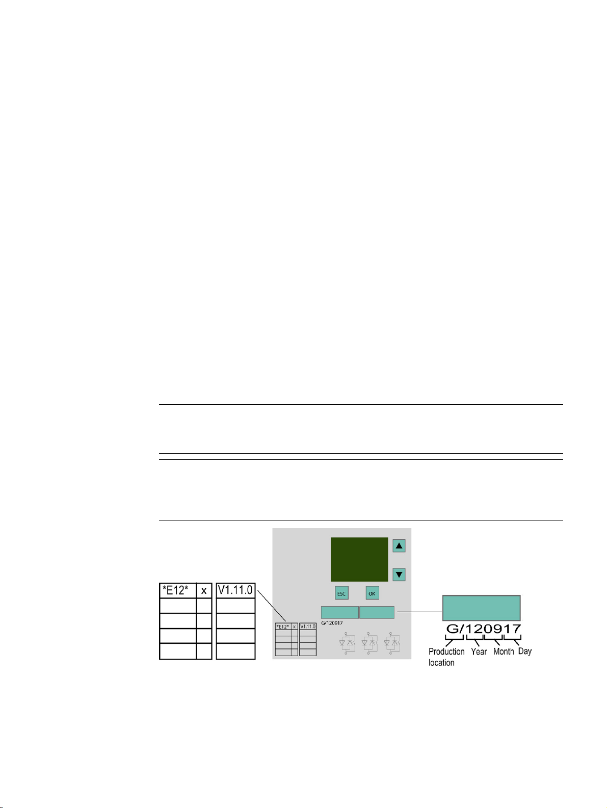
The PROFINET communication module only works with 3RW44 devices with product
version "E12" and firmware version V1.11.0 or higher.
For devices with product version E12 and firmware version 1.10.5, the PROFINET
communication module independently performs a firmware update to version 1.11 after
activation of the fieldbus interface.
PROFINET Communication Module for SIRIUS Soft Starter 3RW44
Manual, 12/2013, A5E31996495002A/RS-AA/001
17

Product description
3.1
Fieldbus interfaces
3.1.1
PROFINET IO
Properties of PROFINET IO
3.1 Fieldbus interfaces
PROFINET IO is an open transmission system with real-time functionality defined in
accordance with the PROFINET standard. This standard defines a manufacturerindependent communication, automation and engineering model.
Accessories for wiring the PROFINET components are available in industrial quality.
● PROFINET discards the hierarchical PROFIBUS master/slave concept and deploys a
provider/consumer principle instead. The modules of an I/O device that will be subscribed
to by an IO controller are defined within the engineering phase.
● The quantity framework is extended in accordance with the options offered on
PROFINET IO. Parameter limits are not exceeded during configuration.
● The transmission rate is 100 Mbps.
● The configuration interface for users is generally the same as that on PROFIBUS DP (the
system is configured in STEP 7 > HW CONFIG).
● Integrated switch with 2 ports
● Supported Ethernet services: ping, arp, network diagnostics (SNMP)/MIB-2, LLDP
● Port diagnostics
● Device replacement without removable medium/programming device
● MRP (Media Redundancy Protocol)
● Supports PROFIenergy
● NTP (Network Time Protocol)
PROFINET Communication Module for SIRIUS Soft Starter 3RW44
18 Manual, 12/2013, A5E31996495002A/RS-AA/001
Product description
Data transfer options
Communication between PC with Soft Starter ES 2007 + SP5 parameter assignment software (IO Supervisor) and
3RW44 via PROFINET
Communication between Soft Starter ES 2007 + SP5 PC parameter assignment software and 3RW44 via the local
Additional information
3.1 Fieldbus interfaces
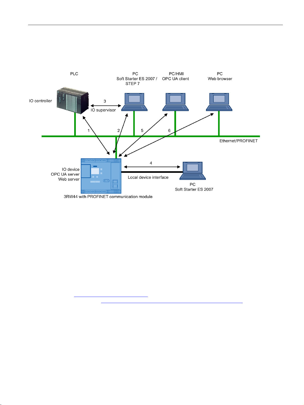
The following figure shows an overview of the communication functions supported by
SIRIUS 3RW44 soft starters, which are described in more detail in the following sections:
1 Communication between PLC (IO controller) and 3RW44 (IO device) via PROFINET / Ethernet
2
3 Communication between PC with Soft Starter ES 2007 + SP5 parameter assignment software and 3RW44 via
SIMATIC S7 (3RW44 integrated in STEP 7)
4
device interface (point-to-point via RS232 or USB)
5 Communication between PC or HMI with OPC UA client and 3RW44 via Ethernet/OPC UA
6 Communication between PC with web browser and 3RW44 via TCP/IP and HTTP/HTTPS (web server)
You can find additional information about PROFINET on the Internet
(http://www.siemens.com/profinet) and in system manual "SIMATIC PROFINET System
Description (http://support.automation.siemens.com/WW/view/de/19292127)".
PROFINET Communication Module for SIRIUS Soft Starter 3RW44
Manual, 12/2013, A5E31996495002A/RS-AA/001
19
Product description
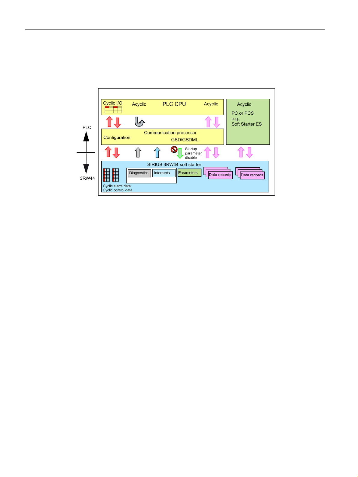
3.2
Communication principle
3.2 Communication principle
The following figure shows the communication principle, in which different data are
transferred depending on the operating mode:
PROFINET Communication Module for SIRIUS Soft Starter 3RW44
20 Manual, 12/2013, A5E31996495002A/RS-AA/001
Product description
3.3
Display when PROFINET communication module is activated
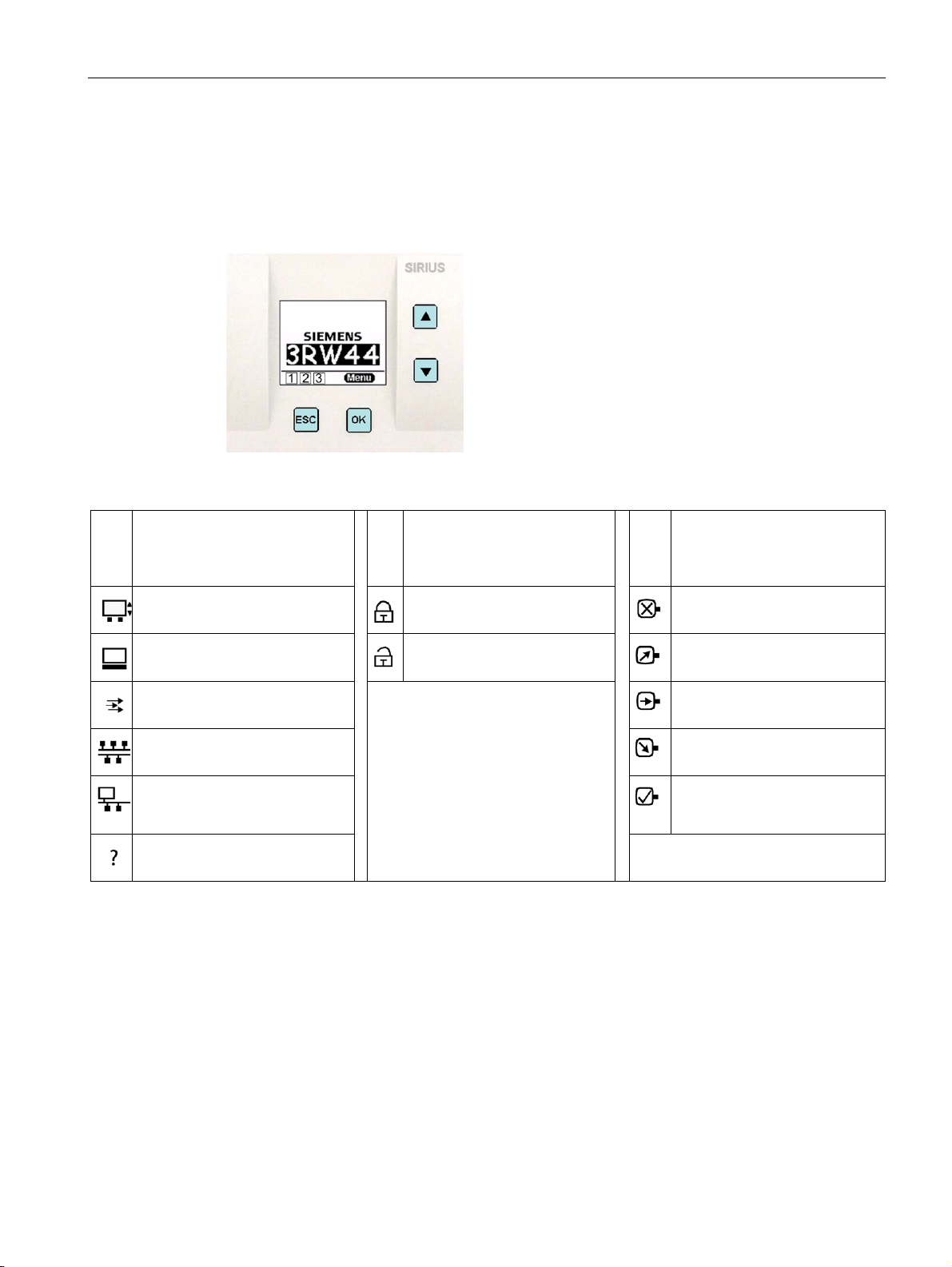
3.3 Display when PROFINET communication module is activated
There is a graphic display on the front of the device from which the functions and states of
the 3RW44 can be read in plain text and with the help of symbols when control voltage is
applied.
1 Shows the operator panel that
currently has control priority and
is thus issuing the control
commands for the motor.
Display with keys
2 Indicates the user level setting 3 Indicates the current motor
status
Customer read only
No motor
Serial interface
Customer write
Control inputs
PLC via fieldbus (PROFIBUS,
PROFINET)
PC via bus (Soft Starter ES 2007
or web server or OPC UA
server)
No control device
Run-up
Motor is running
Coasting down
Motor ready to start
PROFINET Communication Module for SIRIUS Soft Starter 3RW44
Manual, 12/2013, A5E31996495002A/RS-AA/001
21
Product description
3.4
Fieldbus for PROFINET menu structure
Additional menu commands when PROFINET communication module is activated
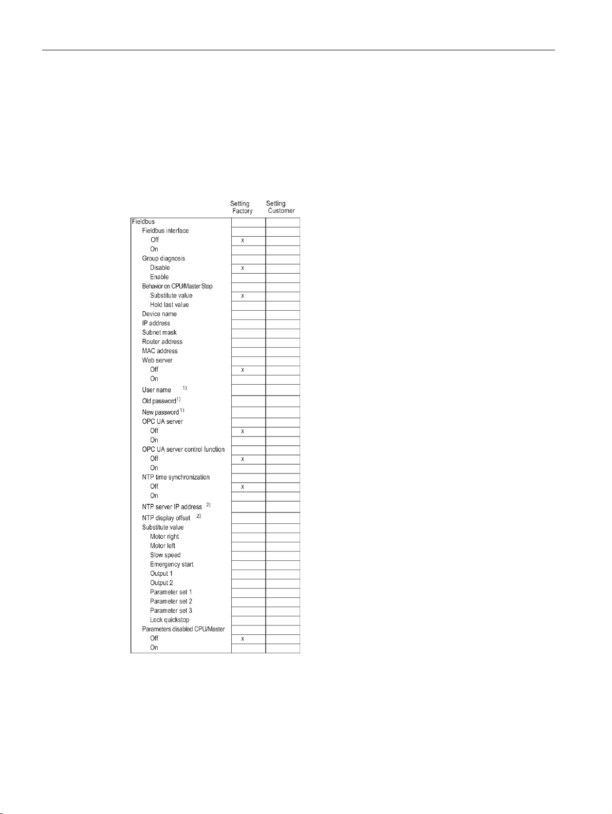
3.4 Fieldbus for PROFINET menu structure
On the display of the 3RW44 soft starter, select "Settings > Fieldbus > Fieldbus interface >
On" to activate the PROFINET communication module. The following menu structure is
displayed:
1)
only if web server is activated
2)
only if NTP time synchronization is activated
PROFINET Communication Module for SIRIUS Soft Starter 3RW44
22 Manual, 12/2013, A5E31996495002A/RS-AA/001

4
WARNING
Hazardous Voltage.
4.1
Inserting the PROFINET communication module
NOTICE
Danger of material damage.
Note
Note
Can Cause Death or Serious Injury. Turn off and lock out all power supplying this device
before working on this device.
Read the information in operating instructions "PROFINET Communication Module for Soft
Starter 3RW44", order no. 3ZX1012-0RW40-0NA1.
Before inserting the PROFINET communication module, disconnect the power to the
3RW44 soft starter.
The PROFINET communication module only works with 3RW44 devices with product
version "E12" and firmware version V1.11.0 or higher (see Product description (Page 17)).
For devices with product version E12 and firmware version 1.10.5, the PROFINET
communication module independently performs a firmware update to version 1.11 after
activation of the fieldbus interface.
PROFINET Communication Module for SIRIUS Soft Starter 3RW44
Manual, 12/2013, A5E31996495002A/RS-AA/001
23
Installation / removal
Step
Description
Note
Combinations of PROFINET connecting cables
4.1 Inserting the PROFINET communication module
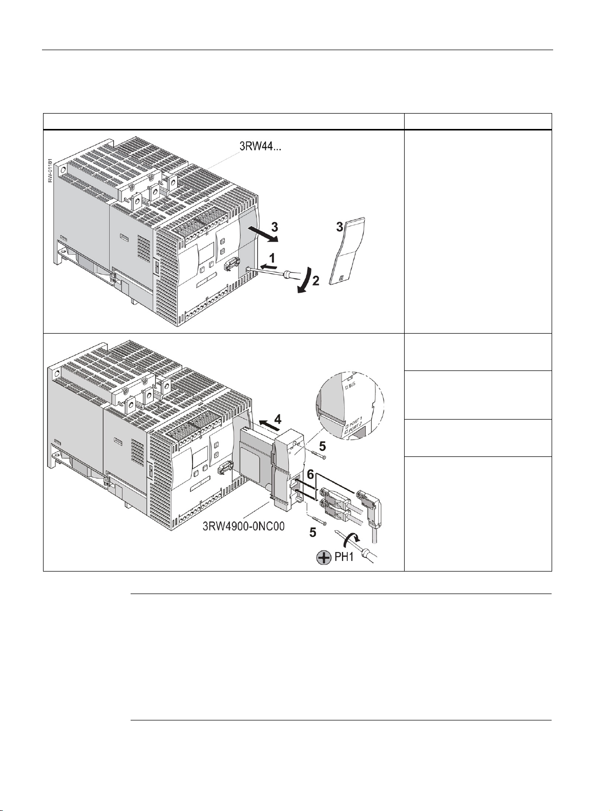
To install the PROFINET communication module, follow these steps:
Slide a small screwdriver into the
opening of the cover of the
3RW44 soft starter (1). Gently
press down with the screwdriver
(2) and remove the cover (3).
The following combinations of connector designs for PROFINET connecting cables are
possible:
• One straight connector
• Two straight connectors
• One angled connector
• One straight and one angled connector
Insert the PROFINET
communication module into the
device (4).
Fasten the PROFINET
communication module with the
enclosed screws (5). Torque 0.8
to 1.2 Nm (7 to 10.3 lb.in).
Insert the PROFINET connecting
cable into one of the sockets of
the communication module (6).
Switch on the supply voltage.
The "BUS" LED flashes yellow.
The communication module has
been inserted correctly, but has
not yet been activated (activation,
see section Commissioning
(Page 31)).
PROFINET Communication Module for SIRIUS Soft Starter 3RW44
24 Manual, 12/2013, A5E31996495002A/RS-AA/001
Installation / removal
4.2
Ethernet cable to RJ45 socket
NOTICE
Ethernet connector
4.3
Removal of the PROFINET communication module
Step
Description
4.2 Ethernet cable to RJ45 socket
The Ethernet cable is connected to the basic unit.
Connect using only industrial Ethernet connectors, e.g.
• Siemens IE FC RJ45 PLUG 180 2x2, RJ45 connector (10/100MBIT/S) with robust metal
housing and Fast Connect connection method, for IE FC Cable 2x2 180° cable outlet,
order number 6GK1901-1BB10-2AA0 or
• Siemens IE FC RJ45 PLUG 90 2x2, RJ45 connector (10/100MBIT/S) with robust metal
housing and Fast Connect connection method, for IE FC Cable 2x2 90° cable outlet,
order number 6GK1901-1BB20-2AA0.
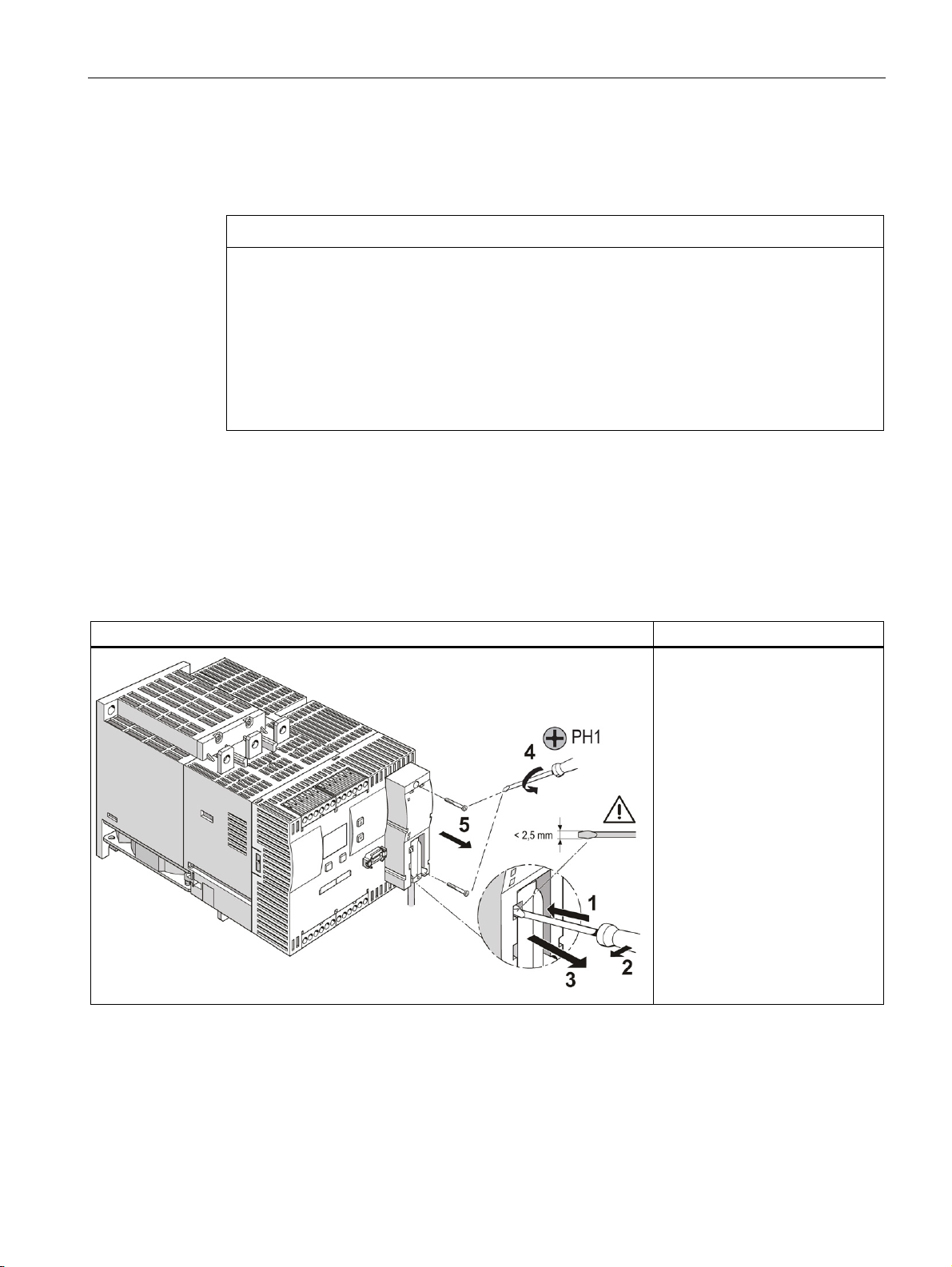
To remove the PROFINET communication module, follow these steps:
Slide a small screwdriver into the
opening of the PROFINET
communication module (1).
Gently press to the left with the
screwdriver (2) and withdraw the
PROFINET connecting cable (3).
Unscrew the screws on the
PROFINET communication
module (4) and withdraw the
communication module (5).
PROFINET Communication Module for SIRIUS Soft Starter 3RW44
Manual, 12/2013, A5E31996495002A/RS-AA/001
25

Installation / removal
4.3 Removal of the PROFINET communication module
PROFINET Communication Module for SIRIUS Soft Starter 3RW44
26 Manual, 12/2013, A5E31996495002A/RS-AA/001

5
5.1
Configuring soft starters
5.1.1
Configuring with a GSD file
General Station Description (GSD)
Configuring with a GSD file
5.1.2
Assigning parameters with the "Soft Starter ES 2007" software
Configuring refers to the configuring and the assigning of parameters of soft starters.
● Configuring: systematic arranging of individual soft starters (configuration).
● Assigning parameters: assigning parameters using the configuring software.
You can find additional information on parameters in the section "Data formats and data
records (Page 75)".
Refer to the glossary for the definition of the generic station description.
You configure the soft starter using the GSD file. The soft starter is integrated into your
system as an IO device by means of the GSD file.
You require a GSD file, which you can download from the Internet at:
PROFINET GSD files (http://support.automation.siemens.com/WW/view/de/38702563) >
PROFINET communication module
Following installation of the GSD file, you can find the SIRIUS Soft Starter 3RW44 PN in the
HW Catalog of STEP 7 V5 under "HW Catalog > PROFINET IO > Switching Devices > Motor
starter > Soft starter -> 3RW44". Insert your device variant into the PROFINET IO system.
You can find additional information on working with GSD files and on parameter assignment
of the PROFINET interface in the system manual SIMATIC PROFINET System Description
(http://support.automation.siemens.com/WW/view/de/19292127).
The "Soft Starter ES 2007 + SP5" software can be used to assign the SIRIUS 3RW44 soft
starter parameters via the device interface (point-to-point connection by means of the RS232
interface cable or USB interface cable).
"Soft Starter ES 2007" is the central software for commissioning, operation, and diagnostics
of SIRIUS 3RW44 soft starters.
PROFINET Communication Module for SIRIUS Soft Starter 3RW44
Manual, 12/2013, A5E31996495002A/RS-AA/001
27

Configuring/assigning parameters
5.1.3
Diagnostics package
5.2
Configuring the properties of 3RW44 PN as IO device
Assigning the device name and IP parameters for an IO device
Assigning the device name using the configuration tool of the automation system
5.2 Configuring the properties of 3RW44 PN as IO device
There are two options for assigning parameters for the PROFINET communication module:
● Stand-alone program on PC or programming device with PROFINET connection (point-
to-point)
● Integration with the object manager (OM) in STEP 7
You can find detailed information about "Soft Starter ES" in the online help for the
program.
You can download the "Soft Starter ES 2007" software under Test version
(http://support.automation.siemens.com/WW/view/de/28323168). This is a free, 14-day test
version.
A free diagnostics package is available for the 3RW44 soft starters. It contains HMI
diagnostics masks for a touch panel. The diagnostics package is available in German and
English. You can download the diagnostics package
at (http://support.automation.siemens.com/WW/view/de/28557893).
PROFINET IO communication requires setting and configuring the IO device name and the
IP parameters.
The device name and the IP parameters can be assigned in different ways:
● Assigning the device name using the configuration tool of the automation system
● Configuring the device name using the "Soft Starter ES 2007" software and transferring it
to the device
● Assigning the device name via the display in the 3RW44 basic device
The device name is assigned during the commissioning phase by the configuration tool of
the automation system (e.g., STEP 7) and transferred to the IO device via Ethernet. For the
transfer, the soft starter must be connected and accessible via the Ethernet interface. The
device can be accessed via LAN using the MAC address (e.g., 00-0E-8C-BD-1F-27) printed
on the front of the communication module.
PROFINET Communication Module for SIRIUS Soft Starter 3RW44
28 Manual, 12/2013, A5E31996495002A/RS-AA/001

Configuring/assigning parameters
Configuring the device name using the "Soft Starter ES 2007" software and transferring it to
the device
Note
Transferring the device parameters
Note
Changing the device name
Transferring IP parameters
5.2 Configuring the properties of 3RW44 PN as IO device
1. When the user performs the configuration, the device is given a technological name (e.g.:
Motor-1). STEP 7 automatically assigns an IP address. This requires that "Assign IP
address via IO controller" is activated.
2. The user assigns the device name to an IO device based on the MAC address and
transfers the name, for example, with the "Edit Ethernet Node" function".
3. The user downloads the configuration to the IO controller
4. The IO controller assigns the IP parameters based on the device name during startup.
In this case, the device name must be configured under "Device parameters > Field bus
interface > PROFINET Parameters > Station" and the "Overwrite device name in device"
parameter must be activated.
It is always possible to transfer the device parameters via the local device interface.
If the IP address has already been configured in a different way, the device parameters can
be transferred via PROFINET, too.
Any change of the device name using the "PROFINET Parameters" dialog box of "Soft
Starter ES 2007" requires a restart of the communication interface. A new start interrupts all
Ethernet and PROFINET links and reestablishes them afterward.
The IP parameters, consisting of IP address, subnet mask, and router can also be assigned
in various ways and transferred to the IO device.
PROFINET Communication Module for SIRIUS Soft Starter 3RW44
Manual, 12/2013, A5E31996495002A/RS-AA/001
29

Configuring/assigning parameters
Note
Deleting IP parameters
Note
Transferring the device parameters
Note
Assigning the IP parameters
Note
Restarting the communication interface
Saving the parameters retentively
5.2 Configuring the properties of 3RW44 PN as IO device
Possibilities for this are:
● The IO controller assigns the IP parameters to the IO device.
IP parameters assigned by the IO controller are not stored retentively in the device, i.e.,
they are deleted when the supply voltage is switched off.
● The IP parameters are configured with the "Soft Starter ES 2007" software and
transferred to the device. In this case, the "Overwrite IP parameters in device" parameter
under "PROFINET Parameters > IP-Parameters" must be activated.
It is always possible to transfer the device parameters via the local device interface.
If the PROFINET IO device name or the IP address has already been configured in a
different way, the device parameters can also be transferred via PROFINET.
The IP parameters can be transferred to the selected device using the following functions
of the "Soft Starter ES 2007" software.
• Select "Target System > Edit Ethernet Node". This function is not identical to the
parameter assignment of the IP parameters using the "PROFINET Parameters" dialog
box.
• Select "PROFINET Parameters > IP-Parameters". The "Overwrite IP parameters in
device" parameter must be activated.
Any change of the IP parameters using the "PROFINET Parameters" dialog box of "Soft
Starter ES 2007" requires a restart of the communication interface.
A new start of the communication interface interrupts all Ethernet and PROFINET links
and reestablishes them afterward.
● Input of IP address, subnet mask, router address via the display of the 3RW44 (for
procedure, see Parameter settings in the soft starter under Fieldbus (Page 36)).
In order to save the modified parameters retentively, select "Save settings" in the menu of
the 3RW44 soft starter.
PROFINET Communication Module for SIRIUS Soft Starter 3RW44
30 Manual, 12/2013, A5E31996495002A/RS-AA/001
 Loading...