

Siemens SIRIUS ACT 3SU1 System Manual

___________________
___________________
___________________
___________________
___________________
___________________
___________________
___________________
___________________
___________________
___________________
___________________
___________________
___________________
___________________
___________________
___________________
Industrial Controls
Command and signaling devices
SIRIUS ACT 3SU1 pushbuttons
and signaling devices
System Manual
08/2018
A5E03457306020A/RS
Introduction
1
Safety notes
2
ATEX for intrinsically safe
circuits
3
Overview
4
3SU10 pushbuttons and
indicator lights
5
3SU11 complete units
6
3SU12 compact units
7
3SU14 modules
8
3SU15 holders
9
3SU18 enclosures
10
AS-Interface 3SU14
11
IO-Link 3SU14
12
3SU19 accessories
13
Technical specifications
14
Dimension drawings
15
Application examples
16
Appendix
A
-AK/010
Siemens AG
Division Digital Factory
Postfach 48 48
90026 NÜRNBERG
GERMANY
Ⓟ
Copyright © Siemens AG 2014.
All rights reserved
Legal information
Warning notice system
DANGER
indicates that death or severe personal injury will result if proper precautions are not taken.
WARNING
indicates that death or severe personal injury may result if proper precautions are not taken.
CAUTION
indicates that minor personal injury can result if proper precautions are not taken.
NOTICE
indicates that property damage can result if proper precautions are not taken.
Qualified Personnel
personnel qualified
Proper use of Siemens products
WARNING
Siemens products may only be used for the applications described in the catalog and in the relevant technical
ambient conditions must be complied with. The information in the relevant documentation must be observed.
Trademarks
Disclaimer of Liability
This manual contains notices you have to observe in order to ensure your personal safety, as well as to prevent
damage to property. The notices referring to your personal safety are highlighted in the manual by a safety alert
symbol, notices referring only to property damage have no safety alert symbol. These notices shown below are
graded according to the degree of danger.
If more than one degree of danger is present, the warning notice representing the highest degree of danger will
be used. A notice warning of injury to persons with a safety alert symbol may also include a warning relating to
property damage.
The product/system described in this documentation may be operated only by
task in accordance with the relevant documentation, in particular its warning notices and safety instructions.
Qualified personnel are those who, based on their training and experience, are capable of identifying risks and
avoiding potential hazards when working with these products/systems.
for the specific
Note the following:
documentation. If products and components from other manufacturers are used, these must be recommended
or approved by Siemens. Proper transport, storage, installation, assembly, commissioning, operation and
maintenance are required to ensure that the products operate safely and without any problems. The permissible
All names identified by ® are registered trademarks of Siemens AG. The remaining trademarks in this publication
may be trademarks whose use by third parties for their own purposes could violate the rights of the owner.
We have reviewed the contents of this publication to ensure consistency with the hardware and software
described. Since variance cannot be precluded entirely, we cannot guarantee full consistency. However, the
information in this publication is reviewed regularly and any necessary corrections are included in subsequent
editions.
3ZX1012-0SU10-0AC0
08/2018 Subject to change

Table of contents
1 Introduction ........................................................................................................................................... 13
2 Safety notes .......................................................................................................................................... 21
3 ATEX for intrinsically safe circuits .......................................................................................................... 25
4 Overview............................................................................................................................................... 29
5 3SU10 pushbuttons and indicator lights ................................................................................................. 41
1.1 Responsibility of the user for system configuration and functionality ..................................... 13
1.2 Target group ........................................................................................................................... 13
1.3 Purpose of this documentation ............................................................................................... 13
1.4 Required knowledge ............................................................................................................... 14
1.5 Scope of validity of the system manual .................................................................................. 14
1.6 Further documentation ............................................................................................................ 14
1.7 Siemens Industry Online Support ........................................................................................... 15
1.8 Siemens Industry Online Support app .................................................................................... 17
1.9 Technical Assistance .............................................................................................................. 17
1.10 Configurator for SIRIUS ACT command devices and signaling devices ................................ 18
1.11 Advantages through energy efficiency .................................................................................... 19
1.12 Recycling and disposal ........................................................................................................... 19
2.1 Intended use ........................................................................................................................... 22
2.2 Current information about operational safety ......................................................................... 23
2.3 Security information ................................................................................................................ 24
4.1 Overview of the device range ................................................................................................. 29
4.2 Application areas .................................................................................................................... 33
4.3 Media resistance ..................................................................................................................... 33
4.4 Failure rates ............................................................................................................................ 34
4.5 Types of 3SU1 actuating elements and signaling elements ................................................... 34
4.5.1 Design of a 3SU1 actuating or signaling element ................................................................... 34
4.5.2 3SU10 actuating and signaling elements ............................................................................... 35
4.5.3 3SU15 holders ........................................................................................................................ 36
4.5.4 3SU14 modules ...................................................................................................................... 38
4.5.5 Design of a 3SU10 and 3SU11 command point ..................................................................... 38
5.1 3SU10 devices for use on 3-slot holder .................................................................................. 41
5.1.1 22.5 mm pushbuttons ............................................................................................................. 41
5.1.2 22.5 mm illuminated pushbuttons ........................................................................................... 45
5.1.3 30.5 mm pushbuttons and illuminated pushbuttons ............................................................... 47
SIRIUS ACT 3SU1 pushbuttons and signaling devices
System Manual, 08/2018, A5E03457306020A/RS-AK/010
3

Table of contents
6 3SU11 complete units .......................................................................................................................... 123
5.1.4 STOP buttons ......................................................................................................................... 49
5.1.5 Twin pushbuttons ................................................................................................................... 50
5.1.6 Mushroom pushbuttons ......................................................................................................... 52
5.1.7 Special variants of mushroom pushbuttons ........................................................................... 56
5.1.8 Illuminated mushroom pushbuttons ....................................................................................... 57
5.1.9 EMERGENCY STOP mushroom pushbuttons ...................................................................... 61
5.1.10 22.5 mm indicator lights ......................................................................................................... 66
5.1.11 22.5 mm illuminated pushbuttons with locked handle ........................................................... 67
5.1.12 30.5 mm indicator lights ......................................................................................................... 68
5.1.13 Selector switches ................................................................................................................... 69
5.1.13.1 Selector switches ................................................................................................................... 69
5.1.13.2 Selector switch 22.5 mm with short handle ........................................................................... 71
5.1.13.3 Selector switch 22.5 mm with long handle ............................................................................. 74
5.1.13.4 Selector switch 22.5 mm with rotary knob ............................................................................. 76
5.1.14 30.5 mm selector switches ..................................................................................................... 77
5.1.15 Toggle switches ..................................................................................................................... 80
5.1.16 22.5 mm key-operated switches ............................................................................................ 81
5.1.17 Selector switch 22.5 mm with key monitoring ........................................................................ 85
5.1.18 30.5 mm key-operated switches ............................................................................................ 87
5.1.19 ID key-operated switches ....................................................................................................... 88
5.1.19.1 Design of a command point with ID key-operated switch ...................................................... 89
5.1.19.2 Operating principle of the command point with ID key-operated switch ................................ 91
5.1.19.3 New functions as of firmware 2.0.0 ........................................................................................ 96
5.1.20 Devices with inscription .......................................................................................................... 98
5.1.20.1 22.5 mm pushbuttons with standard inscription ..................................................................... 98
5.1.20.2 Twin pushbuttons with standard inscription ........................................................................... 99
5.1.20.3 Inscription of actuating and signaling elements ................................................................... 102
5.2 3SU10 devices for use on 4-slot holder ............................................................................... 104
5.2.1 Coordinate switches ............................................................................................................. 104
5.2.2 Selector switches 4 switch positions .................................................................................... 108
5.3 Mounting .............................................................................................................................. 109
5.3.1 Front plate mounting ............................................................................................................ 109
5.3.2 Mounting on printed-circuit boards....................................................................................... 111
5.3.3 Base mounting for the enclosure ......................................................................................... 112
5.3.4 Installation steps for 22.5 mm devices ................................................................................. 113
5.3.5 Installation steps for 30.5 mm devices ................................................................................. 115
5.3.6 Mounting a command point with ID key-operated switch .................................................... 116
5.3.7 Alignment ............................................................................................................................. 117
5.3.8 Disassembly steps for 22.5 mm devices ............................................................................. 118
5.3.9 Disassembly steps for 30.5 mm devices ............................................................................. 121
5.3.10 Disassembly of the button .................................................................................................... 122
6.1 Product description .............................................................................................................. 123
6.2 3SU11 devices for use on 3-slot holder ............................................................................... 124
6.2.1 Pushbuttons ......................................................................................................................... 124
6.2.2 Illuminated pushbuttons ....................................................................................................... 128
6.2.3 Mushroom pushbuttons ....................................................................................................... 132
6.2.4 EMERGENCY STOP mushroom pushbuttons .................................................................... 133
6.2.5 Indicator lights ...................................................................................................................... 136
6.2.6 Selector switches ................................................................................................................. 138
SIRIUS ACT 3SU1 pushbuttons and signaling devices
4 System Manual, 08/2018, A5E03457306020A/RS-AK/010

Table of contents
7 3SU12 compact units .......................................................................................................................... 149
8 3SU14 modules .................................................................................................................................. 169
6.2.7 Key-operated switches.......................................................................................................... 140
6.3 3SU11 devices for use on 4-slot holder ................................................................................ 143
6.3.1 Coordinate switches .............................................................................................................. 143
6.4 Mounting ............................................................................................................................... 148
6.4.1 Front plate mounting ............................................................................................................. 148
7.1 Overview ............................................................................................................................... 151
7.1.1 Indicator lights ....................................................................................................................... 151
7.1.2 Indicator lights with "traffic light" LED ................................................................................... 152
7.1.3 Acoustic signaling devices .................................................................................................... 153
7.1.4 Pushbuttons with extended stroke ........................................................................................ 154
7.1.5 Potentiometers ...................................................................................................................... 156
7.1.6 Sensor switches .................................................................................................................... 158
7.2 Mounting ............................................................................................................................... 160
7.2.1 Front plate mounting ............................................................................................................. 160
7.2.2 Front plate mounting for enclosure mounting ....................................................................... 161
7.2.3 Front plate mounting, sensor switches ................................................................................. 162
7.3 Connecting ............................................................................................................................ 168
8.1 Overview ............................................................................................................................... 169
8.1.1 Contact modules ................................................................................................................... 169
8.1.2 Terminal designations ........................................................................................................... 170
8.1.3 Contact modules for front plate mounting ............................................................................. 171
8.1.4 Contact modules for base mounting (enclosure mounting) .................................................. 174
8.1.5 Contact modules for PCB mounting ..................................................................................... 174
8.1.6 Equipping with contact modules ........................................................................................... 175
8.1.6.1 Minimum clearance for front plate mounting ........................................................................ 175
8.1.6.2 Stackability of contact modules ............................................................................................ 176
8.1.6.3 Equipping with contact modules: Actuator (without EMERGENCY STOP) .......................... 177
8.1.6.4 Equipping with contact modules: EMERGENCY STOP on 3-slot holder ............................. 179
8.1.7 LED modules ........................................................................................................................ 183
8.1.8 LED modules for front plate mounting .................................................................................. 184
8.1.9 LED modules 24 V for intrinsic safety (front plate mounting) ............................................... 186
8.1.10 LED modules for base mounting (enclosure mounting) ....................................................... 187
8.1.11 LED modules for 24 V intrinsic safety (floor mounting) ........................................................ 189
8.1.12 LED modules for PCB mounting ........................................................................................... 189
8.1.13 LED test module ................................................................................................................... 190
8.1.14 ASIsafe F adapters for front plate mounting ......................................................................... 191
8.1.15 AS-Interface modules for front plate mounting ..................................................................... 193
8.1.16 AS-Interface modules for base mounting (enclosure mounting) .......................................... 194
8.1.17 Electronic modules for ID key-operated switches ................................................................. 195
8.1.18 Electronic module for IO-Link ............................................................................................... 196
8.1.19 Support terminal for front plate mounting ............................................................................. 198
8.1.20 Support terminal for base mounting (enclosure mounting)................................................... 198
8.2 Mounting ............................................................................................................................... 199
8.2.1 Front plate mounting ............................................................................................................. 199
8.2.1.1 Contact and LED modules .................................................................................................... 199
8.2.1.2 AS-Interface modules, electronic modules for ID key-operated switch / IO-Link ................. 200
SIRIUS ACT 3SU1 pushbuttons and signaling devices
System Manual, 08/2018, A5E03457306020A/RS-AK/010
5

Table of contents
9 3SU15 holders ..................................................................................................................................... 213
10 3SU18 enclosures................................................................................................................................ 219
11 AS-Interface 3SU14 ............................................................................................................................. 253
8.2.1.3 Disassembling modules ....................................................................................................... 201
8.2.2 Front plate mounting for enclosure mounting ...................................................................... 202
8.2.2.1 Front plate mounting for enclosures .................................................................................... 202
8.2.2.2 Dismantling front plate mounting on enclosures .................................................................. 204
8.2.3 Mounting on printed-circuit boards....................................................................................... 205
8.2.4 Base mounting for the enclosure ......................................................................................... 207
8.2.4.1 Equipping with contact and LED modules ........................................................................... 207
8.2.4.2 Disassembling modules ....................................................................................................... 208
8.2.4.3 AS-Interface modules, electronic modules for IO-Link ........................................................ 208
8.3 Connecting ........................................................................................................................... 209
8.3.1 Contact and LED modules, support terminal ....................................................................... 209
8.3.2 Electronic modules for ID key-operated switches ................................................................ 211
8.3.3 AS-Interface modules and electronic module for IO-Link .................................................... 212
9.1 Holders ................................................................................................................................. 213
9.2 Holders with modules ........................................................................................................... 217
10.1 Enclosures for actuating and signaling elements ................................................................ 219
10.1.1 Overview of empty enclosures ............................................................................................. 220
10.1.2 Mounting positions ............................................................................................................... 224
10.1.3 Mounting .............................................................................................................................. 225
10.1.3.1 Base mounting ..................................................................................................................... 226
10.1.3.2 Front plate mounting for enclosures .................................................................................... 228
10.1.3.3 Mounting the enclosure cover .............................................................................................. 231
10.1.3.4 Mounting of connection pieces ............................................................................................ 232
10.1.3.5 Mounting of screw glands for AS-Interface bus ................................................................... 236
10.2 Enclosures with EMERGENCY STOP devices ................................................................... 237
10.2.1 Overview of enclosures with EMERGENCY STOP mushroom pushbuttons ...................... 238
10.2.2 Palm pushbutton with EMERGENCY STOP function .......................................................... 239
10.3 Enclosures with standard fittings ......................................................................................... 240
10.3.1 Palm pushbutton .................................................................................................................. 242
10.3.2 Enclosures with standard fittings for AS-Interface ............................................................... 243
10.4 3SU18..-3 two-hand operation console ............................................................................... 244
10.4.1 Application areas.................................................................................................................. 244
10.4.2 Function ............................................................................................................................... 244
10.4.3 Overview of two-hand operation consoles ........................................................................... 245
10.4.4 Mounting .............................................................................................................................. 247
10.4.4.1 Installation and wiring of two-hand operation console ......................................................... 247
10.4.4.2 Mounting on stand ............................................................................................................... 249
10.4.5 Equipment ............................................................................................................................ 251
11.1 Application areas.................................................................................................................. 253
11.1.1 Application area of the AS-Interface modules ..................................................................... 253
11.1.2 Application areas for AS-Interface modules for front plate mounting .................................. 254
11.2 ASIsafe F adapters for front plate mounting ........................................................................ 255
11.3 AS-Interface modules for front plate mounting .................................................................... 257
SIRIUS ACT 3SU1 pushbuttons and signaling devices
6 System Manual, 08/2018, A5E03457306020A/RS-AK/010

Table of contents
12 IO-Link 3SU14 .................................................................................................................................... 303
11.4 AS-Interface modules for base mounting (enclosure mounting) .......................................... 258
11.5 Enclosure with standard equipment for AS-Interface ........................................................... 259
11.5.1 Equipping with AS-Interface modules by the customer ........................................................ 260
11.6 Mounting and disassembly of the AS-Interface modules for front plate mounting ............... 261
11.6.1 Installation options ................................................................................................................ 261
11.6.2 Mounting ............................................................................................................................... 262
11.6.3 Removal ................................................................................................................................ 264
11.7 Mounting and disassembling AS-Interface modules (3SU1400-1E.10-6AA0) ..................... 265
11.8 Installing and dismantling AS-Interface modules for base mounting .................................... 266
11.8.1 Mounting / installation positions ............................................................................................ 266
11.8.2 Mounting position of AS-Interface slave ............................................................................... 269
11.8.3 Mounting position of AS-Interface F slave ............................................................................ 270
11.8.4 Mounting of the contact modules and AS-Interface F-Safe slaves ...................................... 271
11.8.5 Mounting the contact modules and AS-Interface modules ................................................... 272
11.8.6 Removal of the modules ....................................................................................................... 273
11.9 Connecting ............................................................................................................................ 274
11.9.1 Connection with AS-Interface modules ................................................................................. 274
11.9.2 Connecting the ASIsafe modules for front plate mounting ................................................... 274
11.9.3 Terminal labeling and conductor cross-sections (AS-Interface modules for front plate
mounting) .............................................................................................................................. 280
11.9.4 Connection option AS-Interface bus (AS-Interface modules for base mounting) ................. 282
11.9.5 Terminal labeling and conductor cross sections (AS-Interface modules for base
mounting) .............................................................................................................................. 284
11.10 Configuring the AS-Interface ................................................................................................
288
11.10.1 Setting the AS-i address ....................................................................................................... 288
11.10.2 Addressing the AS-Interface modules for front plate mounting ............................................ 289
11.10.3 Addressing the AS-Interface modules for base mounting .................................................... 291
11.11 Diagnosis of ASIsafe F adapters for front plate mounting .................................................... 293
11.12 Diagnosis of AS-Interface modules for base mounting ........................................................ 294
11.13 Wiring examples ................................................................................................................... 295
12.1 Configuring the IO-Link ......................................................................................................... 303
12.1.1 Combinations ........................................................................................................................ 303
12.1.2 Configuring with STEP 7 and the S7-PCT Port Configuration Tool ..................................... 304
12.1.2.1 Basic procedure and prerequisites ....................................................................................... 304
12.1.2.2 Configuration ......................................................................................................................... 305
12.1.3 Configuring with the S7-PCT Stand Alone Port Configuration Tool ..................................... 306
12.1.3.1 Application ............................................................................................................................ 306
12.1.3.2 Basic procedure and prerequisites ....................................................................................... 306
12.1.3.3 Configuration ......................................................................................................................... 307
12.1.4 Acyclic data exchange with the IO_LINK_MASTER function block ...................................... 307
12.1.5 Acyclic data exchange with the IO_LINK_DEVICE function block ....................................... 308
12.1.6 Replacing an IO-Link device ................................................................................................. 309
12.1.6.1 Introduction ........................................................................................................................... 309
12.1.6.2 Replacing an IO-Link device (according to IO-Link specification V1.0) ................................ 309
12.1.6.3 Replacing an IO-Link Device (according to IO-Link specification V1.1) ............................... 311
12.1.7 Integration into the SIMATIC environment............................................................................ 311
SIRIUS ACT 3SU1 pushbuttons and signaling devices
System Manual, 08/2018, A5E03457306020A/RS-AK/010
7

Table of contents
12.2 Electronic modules for ID key-operated switches ................................................................ 312
12.2.1 Design of a command point with ID key-operated switch .................................................... 312
12.2.2 Operating principle of the command point with ID key-operated switch .............................. 314
12.2.3 New functions as of firmware 2.0.0 ...................................................................................... 319
12.2.4 Compatibility ......................................................................................................................... 321
12.2.5 Parameters ........................................................................................................................... 322
12.2.5.1 Parameters ........................................................................................................................... 322
12.2.5.2 "Incremental switching mode" parameter ............................................................................ 323
12.2.5.3 "Deactivation of the switch-off function" parameter ............................................................. 323
12.2.5.4 "Switch position memory" parameter ................................................................................... 324
12.2.5.5 “Switch position retentive memory" parameter .................................................................... 324
12.2.5.6 “Individually codable ID keys only" parameter ..................................................................... 325
12.2.5.7 "Switch position delay" parameter ....................................................................................... 325
12.2.5.8 "Select memory range" parameter ....................................................................................... 326
12.2.5.9 "Restore Factory Setting” parameter ................................................................................... 326
12.2.5.10 Manage authorization level (individually encodable ID keys) .............................................. 327
12.2.5.11 Parameters for IO-Link devices (according to IO-Link communication specification
V1.1) ..................................................................................................................................... 333
12.2.6 Process image ..................................................................................................................... 334
12.2.7 Diagnostics ........................................................................................................................... 335
12.2.7.1 IO-Link diagnostics .............................................................................................................. 335
12.2.8 Mounting a command point with ID key-operated switch .................................................... 338
12.2.9 Connecting ........................................................................................................................... 339
12.2.9.1 Electronic modules for the ID key-operated switches for IO-Link ........................................
339
12.3 Electronic modules for IO-Link ............................................................................................. 341
12.3.1 Electronic module for IO-Link ............................................................................................... 341
12.3.2 Functions .............................................................................................................................. 343
12.3.2.1 Input functions ...................................................................................................................... 343
12.3.2.2 Output functions ................................................................................................................... 346
12.3.3 Parameters ........................................................................................................................... 350
12.3.3.1 "Input delay” parameter ........................................................................................................ 351
12.3.3.2 "Inverting input” parameter................................................................................................... 351
12.3.3.3 "Switching input” parameter ................................................................................................. 351
12.3.3.4 "Active edge” parameter input ............................................................................................. 352
12.3.3.5 "Threshold” parameter input ................................................................................................ 352
12.3.3.6 "Inverting output” parameter ................................................................................................ 352
12.3.3.7 "PWM frequency” parameter output .................................................................................... 353
12.3.3.8 "PWM duty cycle” parameter output .................................................................................... 353
12.3.3.9 "Dimming time” parameter output ........................................................................................ 353
12.3.3.10 "Switching output” parameter ............................................................................................... 354
12.3.3.11 "Active edge” parameter output ........................................................................................... 354
12.3.4 Diagnostics ........................................................................................................................... 355
12.3.4.1 IO-Link diagnostics .............................................................................................................. 355
12.3.5 Installing and removing electronic modules for IO-Link ....................................................... 356
12.3.5.1 Installation options ............................................................................................................... 356
12.3.5.2 Installing IO-Link electronic modules for front plate mounting ............................................. 357
12.3.5.3 Mounting position of IO-Link modules for base mounting ................................................... 358
12.3.5.4 Mounting contact modules and IO-Link modules for base mounting ...................................
359
12.3.5.5 Removal of the modules ...................................................................................................... 360
12.3.6 Connecting ........................................................................................................................... 361
12.3.6.1 Electronic modules for IO-Link ............................................................................................. 361
12.3.7 Example of wiring ................................................................................................................. 363
SIRIUS ACT 3SU1 pushbuttons and signaling devices
8 System Manual, 08/2018, A5E03457306020A/RS-AK/010

Table of contents
13 3SU19 accessories ............................................................................................................................. 365
13.1 Influence on the actuators .................................................................................................... 365
13.2 Identification of command points .......................................................................................... 365
13.2.1 Backing labels and backing plates ........................................................................................ 365
13.2.1.1 EMERGENCY STOP ............................................................................................................ 366
13.2.2 Labeling plates ...................................................................................................................... 369
13.2.2.1 Labeling plate 12.5 x 27 mm ................................................................................................. 369
13.2.2.2 Labeling plate 17.5 x 27 mm ................................................................................................. 372
13.2.2.3 Labeling plate 27 x 27 mm .................................................................................................... 374
13.2.2.4 Labeling plates for enclosures (22 x 22 mm) ........................................................................ 376
13.2.2.5 Labeling plates for enclosures with EMERGENCY STOP ................................................... 379
13.2.2.6 Labeling plate for potentiometer ........................................................................................... 380
13.2.2.7 Insert label ............................................................................................................................ 381
13.2.2.8 Customized inscriptions ........................................................................................................ 384
13.2.2.9 Labeling plates for individual printing .................................................................................... 387
13.2.3 Label holders ........................................................................................................................ 388
13.3 Protection .............................................................................................................................. 391
13.3.1 Sealable cap ......................................................................................................................... 391
13.3.2 Protective cap ....................................................................................................................... 392
13.3.3 Protective cap for the food and beverage industry ............................................................... 394
13.3.4 Protective cap, silicone-free .................................................................................................. 400
13.3.5 Dust cap ................................................................................................................................ 401
13.3.6 Sun collar .............................................................................................................................. 402
13.3.7 Protective collar .................................................................................................................... 402
13.3.8 Locking device ......................................................................................................................
406
13.3.9 Locking device with cover ..................................................................................................... 409
13.3.10 Mounting ............................................................................................................................... 410
13.3.10.1 Installation steps for dust cover ............................................................................................ 410
13.3.10.2 Installation steps for locking device ...................................................................................... 411
13.4 Actuators ............................................................................................................................... 413
13.5 Keys ...................................................................................................................................... 414
13.6 ID keys .................................................................................................................................. 415
13.7 USB adapter ......................................................................................................................... 416
13.8 RJ45 adapter ........................................................................................................................ 416
13.9 Sealing plug .......................................................................................................................... 417
13.10 Accessories for enclosures ................................................................................................... 418
13.10.1 Labeling plates for enclosures (22 x 22 mm) ........................................................................ 418
13.10.2 Labeling plates for enclosures with EMERGENCY STOP ................................................... 421
13.10.3 Cable glands and connection pieces .................................................................................... 422
13.10.4 Cable glands and adapters for AS-i ...................................................................................... 423
13.10.5 Enclosure adapter ................................................................................................................. 427
13.10.6 Enclosure mounting adapter ................................................................................................. 428
13.10.7 Enclosure cover monitoring .................................................................................................. 428
13.10.8 Installation steps for enclosure cover monitoring ................................................................. 429
13.11 Miscellaneous accessories ................................................................................................... 432
13.11.1 Square single frame .............................................................................................................. 432
13.11.2 Unit labeling plate ................................................................................................................. 432
SIRIUS ACT 3SU1 pushbuttons and signaling devices
System Manual, 08/2018, A5E03457306020A/RS-AK/010
9

Table of contents
14 Technical specifications ....................................................................................................................... 439
15 Dimension drawings ............................................................................................................................. 459
13.11.3 Additional Accessories ......................................................................................................... 433
13.12 Combination options for accessories ................................................................................... 435
13.13 Use of accessories for the enclosure ................................................................................... 437
13.13.1 Enclosure with recess for labeling plate .............................................................................. 437
13.13.2 Enclosure without recess for labeling plate ......................................................................... 438
14.1 Technical data in Siemens Industry Online Support ............................................................ 439
14.2 Pushbuttons ......................................................................................................................... 440
14.3 Mushroom pushbuttons ....................................................................................................... 442
14.4 EMERGENCY STOP mushroom pushbuttons .................................................................... 444
14.5 Selector switches ................................................................................................................. 445
14.6 Toggle switches ................................................................................................................... 445
14.7 Key-operated switches ......................................................................................................... 446
14.8 Coordinate switches ............................................................................................................. 448
14.9 Indicator lights ...................................................................................................................... 448
14.10 Acoustic signaling devices ................................................................................................... 449
14.11 Potentiometers ..................................................................................................................... 449
14.12 Sensor switches ................................................................................................................... 450
14.13 Two-hand operation console ................................................................................................ 451
14.14 Contact modules .................................................................................................................. 452
14.15 LED modules ........................................................................................................................ 454
14.16 Electronic modules for ID key-operated switches ................................................................ 455
14.17 AS-Interface modules .......................................................................................................... 457
15.1 CAx data .............................................................................................................................. 459
15.2 Mounting dimensions ........................................................................................................... 460
15.3 3SU10 devices ..................................................................................................................... 470
15.3.1 Pushbuttons / illuminated pushbuttons ................................................................................ 470
15.3.2 30.5 mm pushbuttons / illuminated pushbuttons ................................................................. 472
15.3.3 STOP buttons ....................................................................................................................... 472
15.3.4 Twin pushbuttons ................................................................................................................. 473
15.3.5 Mushroom pushbuttons / illuminated mushroom pushbuttons ............................................ 475
15.3.6 EMERGENCY STOP with rotate-to-unlatch mechanism ..................................................... 477
15.3.7 EMERGENCY STOP with pull-to-unlatch mechanism ........................................................ 478
15.3.8 EMERGENCY STOP with lock ............................................................................................ 479
15.3.9 Indicator lights ...................................................................................................................... 482
15.3.10 Selector switches ................................................................................................................. 482
15.3.11 30.5 mm selector switches ................................................................................................... 483
15.3.12 Selector switches 4 switch positions .................................................................................... 484
15.3.13 Toggle switches ................................................................................................................... 484
SIRIUS ACT 3SU1 pushbuttons and signaling devices
10 System Manual, 08/2018, A5E03457306020A/RS-AK/010

Table of contents
15.3.14 Key-operated switches.......................................................................................................... 485
15.3.15 30.5 mm key-operated switches ........................................................................................... 486
15.3.16 ID key-operated switches ..................................................................................................... 487
15.3.17 Coordinate switches .............................................................................................................. 487
15.4 3SU12 devices ...................................................................................................................... 488
15.4.1 Indicator lights ....................................................................................................................... 488
15.4.2 Acoustic signaling devices .................................................................................................... 488
15.4.3 Pushbuttons with extended stroke ........................................................................................ 489
15.4.4 Potentiometers ...................................................................................................................... 490
15.4.5 Sensor switches .................................................................................................................... 490
15.5 3SU14 modules .................................................................................................................... 491
15.5.1 Contact modules for front plate mounting ............................................................................. 491
15.5.2 Contact modules for base mounting ..................................................................................... 494
15.5.3 LED modules for front plate mounting .................................................................................. 496
15.5.4 LED modules for base mounting .......................................................................................... 497
15.5.5 LED modules for PCB mounting ........................................................................................... 498
15.5.6 LED test module for base mounting (enclosure mounting) .................................................. 498
15.5.7 AS-Interface modules for front mounting .............................................................................. 499
15.5.8 AS-Interface modules for base mounting ............................................................................. 502
15.5.9 Electronic modules for ID key-operated switches ................................................................. 503
15.5.10 Electronic modules for IO-Link .............................................................................................. 504
15.6 3SU15 holders ...................................................................................................................... 505
15.6.1 Holders with contact modules ...............................................................................................
506
15.6.2 Holders with contact and LED modules ................................................................................ 508
15.7 3SU18 enclosures ................................................................................................................. 509
15.7.1 Enclosures, plastic ................................................................................................................ 509
15.7.2 Enclosures, metal ................................................................................................................. 514
15.7.3 Two-hand operation console ................................................................................................ 519
15.7.4 Palm pushbutton ................................................................................................................... 525
15.8 Accessories ........................................................................................................................... 527
15.8.1 Labels and label holders ....................................................................................................... 527
15.8.1.1 Labels ................................................................................................................................... 527
15.8.1.2 Label holders ........................................................................................................................ 532
15.8.2 Protection .............................................................................................................................. 538
15.8.2.1 Protective caps ..................................................................................................................... 538
15.8.2.2 Protection for sensor switch .................................................................................................. 542
15.8.2.3 Protective collars ................................................................................................................... 543
15.8.2.4 Locking devices .................................................................................................................... 546
15.8.3 Actuators ............................................................................................................................... 550
15.8.4 Keys ...................................................................................................................................... 551
15.8.5 USB adapter ......................................................................................................................... 553
15.8.6 RJ45 adapter ........................................................................................................................ 554
15.8.7 Accessories for enclosures ................................................................................................... 555
15.8.7.1 Cable glands and connection pieces .................................................................................... 555
15.8.7.2 Adapters for AS-i shaped cables .......................................................................................... 558
15.8.7.3 Adapters for AS-i tab connection ..........................................................................................
559
15.8.7.4 Enclosure cover monitoring .................................................................................................. 563
15.8.8 Miscellaneous accessories ................................................................................................... 563
SIRIUS ACT 3SU1 pushbuttons and signaling devices
System Manual, 08/2018, A5E03457306020A/RS-AK/010
11

Table of contents
16 Application examples ........................................................................................................................... 565
A Appendix ............................................................................................................................................. 575
Index ................................................................................................................................................... 609
16.1 Examples of EMERGENCY STOP shutdown applications ................................................. 565
16.1.1 Emergency stop shutdown to SIL 3 or PL e with a safety relay .......................................... 565
16.1.2 Emergency stop shutdown via AS-i with a Modular Safety System to SIL 3 or PL e .......... 567
16.2 Examples of two-hand operation console applications ........................................................ 569
16.2.1 Safety Evaluation Tool ......................................................................................................... 569
16.2.2 Two-hand operation to SIL 3 or PL e with a safety relay ..................................................... 570
16.2.3 Two-hand operation to SIL 3 or PL e with a Modular Safety System .................................. 572
16.3 Application examples for ID key-operated switches ............................................................ 574
A.1 Process data and data sets ................................................................................................. 575
A.1.1 Electronic module for ID key-operated switches .................................................................. 575
A.1.1.1 Structure of the data sets ..................................................................................................... 575
A.1.1.2 IO-Link communication parameters ..................................................................................... 576
A.1.1.3 Identification data ................................................................................................................. 577
A.1.1.4 System commands - data set (index) 2 ............................................................................... 578
A.1.1.5 Add individually encodable ID key - dataset (index) 79 ....................................................... 579
A.1.1.6 Delete individually encodable ID key - data set (index) 80 .................................................. 579
A.1.1.7 Memory for the individually encodable ID keys (1-30) - data set (index) 81........................ 580
A.1.1.8 Memory for the individually encodable ID keys (31-50) - data set (index) 82 ..................... 582
A.1.1.9 Diagnostics - data set (index) 92 ......................................................................................... 583
A.1.1.10 Diagnostics - dataset (index) 92 (FW 2.0.0 or higher) ......................................................... 584
A.1.1.11 Diagnostics - data set (index) 94 ......................................................................................... 585
A.1.1.12 Diagnostics - dataset (index) 94 (FW 2.0.0 or higher) ......................................................... 585
A.1.1.13 Parameters - Data set (index) 131 ....................................................................................... 586
A.1.1.14 Parameters - Data set (index) 131 (from FW 2.0.0) ............................................................ 587
A.1.2 Electronic module for IO-Link ............................................................................................... 588
A.1.2.1 Structure of the data sets ..................................................................................................... 588
A.1.2.2 IO-Link communication parameters ..................................................................................... 589
A.1.2.3 Identification data ................................................................................................................. 590
A.1.2.4 System commands - data set (index) 2 ............................................................................... 591
A.1.2.5 Process Data Out - data set (index) 67 ...............................................................................
592
A.1.2.6 Process Data In - data set (index) 69 .................................................................................. 593
A.1.2.7 Diagnostics - data set (index) 92 ......................................................................................... 594
A.1.2.8 Diagnostics - data set (index) 94 ......................................................................................... 596
A.1.2.9 Parameters - Data set (index) 131 ....................................................................................... 598
A.2 PSS classification................................................................................................................. 601
A.3 Certifications and approvals ................................................................................................. 608
SIRIUS ACT 3SU1 pushbuttons and signaling devices
12 System Manual, 08/2018, A5E03457306020A/RS-AK/010

1
1.1
Responsibility of the user for system configuration and functionality
1.2
Target group
1.3
Purpose of this documentation
The products described here have been developed to perform safety-related functions as
part of an overall system or machine.
A complete safety-related system generally includes sensors, evaluation units, signaling
devices and concepts for safe tripping.
The manufacturer of a system or machine is responsible for ensuring its correct overall
function.
Siemens AG, its subsidiaries and affiliated companies (hereinafter referred to as "Siemens")
are not able to guarantee all properties of an overall system or machine not designed by
Siemens.
Siemens also does not assume any liability for recommendations that are made or implied in
the following description. No new guarantee, warranty, or liability claims beyond the scope of
the general terms of delivery of Siemens may be derived based on the following description.
This documentation contains information for the following target groups:
● Decision makers
● Technologists
● Project planning engineers
● Commissioning engineers
This System Manual describes the many different possible uses of the
SIRIUS ACT (3SU1) pushbuttons and signaling devices and provides the following
information:
● Information regarding integration of the 3SU1 pushbuttons and signaling devices into the
system environment
● Information on the principle of operation, selection, installation, and connection of
pushbuttons and signaling devices
● Technical information such as dimension drawings
The information in this manual enables you to configure and commission the pushbuttons
and signaling devices.
SIRIUS ACT 3SU1 pushbuttons and signaling devices
System Manual, 08/2018, A5E03457306020A/RS-AK/010
13

Introduction
1.4
Required knowledge
1.5
Scope of validity of the system manual
1.6
Further documentation
Operating Instructions title1)
Article number1)
SIRIUS Complete Units with EMERGENCY STOP 3SU11..-1.
3ZX1012-0SU11-1AA1
Directive
Directive
SIRIUS Two-Hand Operation Consoles 3SU18..-3
3ZX1012-0SU18-3NA1
SIRIUS AS-Interface Module (Base Element) 3SU14..-.E
3ZX1012-0SU14-1EA1
SIRIUS Electronic Module for ID Key-Operated Switches 3SU14..-.G
3ZX1012-0SU14-1GA1
SIRIUS Sensor Switches
3ZX1012-0SU12-1SA1
1)
The documents are available for download free of charge in the Service&Support Portal.
1.4 Required knowledge
A general knowledge of the following areas is needed in order to understand this
documentation:
● Low-voltage industrial controls
● Digital circuit logic
● Automation systems
● AS-Interface
● IO-Link
● Safety technology
The system manual is valid for the present pushbuttons and signaling devices. It contains a
description of the devices that are valid at the time of publication.
SIRIUS AS-Interface Module (Front Plate Mounting) 3SU14.0-1E..0-.AA0 3ZX1012-0SU14-1AA1
SIRIUS AS-Interface Module (Base Mounting) in accordance with the Machinery
SIRIUS Enclosures with EMERGENCY STOP 3SU18..-.N 3ZX1012-0SU18-1NA1
SIRIUS Two-Hand Operation Consoles 3SU18..-3 in accordance with the Machinery
Please observe the following Operating Instructions for this system manual.
3ZX1012-0SU14-1CA1
3ZX1012-0SU18-3AA1
SIRIUS ACT 3SU1 pushbuttons and signaling devices
14 System Manual, 08/2018, A5E03457306020A/RS-AK/010

Introduction
1.7
Siemens Industry Online Support
Information and Service
Link:
Product support
FAQs
Manuals/operating instructions
Certificates
Characteristic curves
Product announcements
Downloads
Application examples
Technical data
Link:
1.7 Siemens Industry Online Support
In Siemens Industry Online Support, you can obtain up-to-date information from our global
support database quickly and simply. To accompany our products and systems, we offer a
wealth of information and services that provide support in every phase of the lifecycle of your
machine or plant – from planning and implementation, through commissioning, up to
maintenance and modernization:
● Product support
● Application examples
● Services
● Forum
● mySupport
Siemens Industry Online Support (https://support.industry.siemens.com/cs/de/en)
You will find here all the information and comprehensive know-how covering all aspects of
your product:
●
Our answers to frequently asked questions.
●
Read online or download, available as PDF or individually configurable.
●
Clearly sorted according to approving authority, type and country.
●
For support in planning and configuring your system.
●
The latest information and news concerning our products.
●
You can find here updates, service packs, HSPs and much more for your product.
●
Function blocks, background and system descriptions, performance statements,
demonstration systems, and application examples, clearly explained and represented.
●
Technical product data for support in planning and implementing your project.
Product support (https://support.industry.siemens.com/cs/ww/en/ps)
SIRIUS ACT 3SU1 pushbuttons and signaling devices
System Manual, 08/2018, A5E03457306020A/RS-AK/010
15

Introduction
mySupport
Personal messages
Inquiries
Notifications
Filters
Favorites / Tags
Entries last viewed
Documentation
Personal data
CAx data
1.7 Siemens Industry Online Support
With "mySupport", your personal workspace, you get the very best out of your Industry
Online Support. Everything to enable you to find the right information every time.
The following functions are now available:
●
Your personal mailbox for exchanging information and managing your contacts
●
Use our online form for specific solution suggestions, or send your technical inquiry
directly to a specialist in Technical Support
●
Make sure you always have the latest information - individually tailored to your needs
●
Simple management and re-use of your filter settings from Product Support and the
Technical Forum
●
Create your own knowledge database by assigning "Favorites" and "Tags" to documents
– simply and efficiently
●
Clear presentation of your last viewed entries
●
Configure your individual documentation from different manuals – quickly and without
complications
●
Change personal data and contact information here
●
Simple access to thousands of items of CAx data such as 3D models, 2D dimension
drawings, EPLAN macros and much more
SIRIUS ACT 3SU1 pushbuttons and signaling devices
16 System Manual, 08/2018, A5E03457306020A/RS-AK/010
Introduction
1.8
Siemens Industry Online Support app
Siemens Industry Online Support app
Link for Android
Link for iOS
Link for Windows Phone
1.9
Technical Assistance
Technical Assistance:
Internet (http://www.siemens.com/sirius/technical-assistance)
1.8 Siemens Industry Online Support app
You can use the Siemens Industry Online Support app to access all the device-specific
information available on the Siemens Industry Online Support portal for a particular article
number, including operating instructions, manuals, datasheets, FAQs etc.
The Siemens Industry Online Support app is available for iOS, Android or Windows Phone
devices. You can download the app from the following links:
Using the support request form in Online Support you can send your query directly to our
Technical Assistance. After describing your query in a few guided steps, you will immediately
be provided with possible suggestions for solving the problem.
Telephone: +49 (0) 911-895-5900 (8:00 a.m. - 5:00 p.m. CET)
Fax: +49 (0) 911-895-5907
E-mail (mailto:technical-assistance@siemens.com)
SIRIUS ACT 3SU1 pushbuttons and signaling devices
System Manual, 08/2018, A5E03457306020A/RS-AK/010
17

Introduction
1.10
Configurator for SIRIUS ACT command devices and signaling
devices
1.10 Configurator for SIRIUS ACT command devices and signaling devices
Various configurators are available online to assist you during the configuration process.
The configurator for SIRIUS ACT pushbuttons and signaling devices and matching
accessories is an easy-to-use selection and configuration tool. You can select the individual
components and plan your system in accordance with your specific requirements. You can
save your selection, export it as a text file or order it directly.
The configurator automatically compiles a document list of the information available in
Service&Support for every component. You can use it as the basis for putting together your
system documentation.
A further aid to configuring your customized device is the Configuration Identification Number
(CIN).
When you finish configuring your customized device, you receive a CIN. With this number,
you can retrieve and order your configuration from anywhere in the world. The CINs are also
saved with the user login and can be selected on your Start page.
Link: Configurator (https://www.siemens.com/sirius-act/configurator
)
SIRIUS ACT 3SU1 pushbuttons and signaling devices
18 System Manual, 08/2018, A5E03457306020A/RS-AK/010

Introduction
1.11
Advantages through energy efficiency
Advantages through energy efficiency
1.12
Recycling and disposal
1.11 Advantages through energy efficiency
Siemens offers you a unique portfolio for efficient energy management in industry – a
process that serves to optimally shape your energy requirement. Operational energy
management is subdivided into three phases:
● Identifying
● Evaluating
● Realizing
Siemens supports you with suitable hardware and software solutions in every phase of a
project.
More information can be found on the Internet
(http://www.automation.siemens.com/mcms/industrial-controls/en/energy-efficiency
The 3SU1 pushbuttons and signaling devices contribute to energy efficiency throughout the
plant as follows:
).
● Low power consumption as a result of LED technology
● Long service life
Figure 1-1 Overview of the energy management process
For environmentally friendly recycling and disposal of your old device, please contact a
company certified for the disposal of old electrical and/or electronic devices and dispose of
the device in accordance with the regulations in your country.
SIRIUS ACT 3SU1 pushbuttons and signaling devices
System Manual, 08/2018, A5E03457306020A/RS-AK/010
19

Introduction
1.12 Recycling and disposal
SIRIUS ACT 3SU1 pushbuttons and signaling devices
20 System Manual, 08/2018, A5E03457306020A/RS-AK/010
2
DANGER
Hazardous voltage. Will cause death or serious injury.
DANGER
Hazardous voltage. Will cause death or serious injury.
Qualified Personnel.
CAUTION
Safe equipment operation
NOTICE
Grounding
NOTICE
Radio interference
Note
No liability shall be accepted for any damage or injuries sustained as a result of improper
use or incorrect dismantling of the equipment (i.e. opening of components other than those
specifically designed to be opened by the user). Any improper handling of the equipment can
result in very serious physical injury.
• Turn off and lock out all power supplying this device before working on this device.
• Secure against switching on again.
• Verify that the equipment is not live.
• Ground and short-circuit.
• Erect barriers around or cover adjacent live parts.
The equipment / system may only be commissioned and operated by qualified personnel.
For the purpose of the safety information in this documentation, a “qualified person” is
someone who is authorized to energize, ground, and tag equipment, systems, and circuits
in accordance with established safety procedures.
Safe operation of the equipment is only ensured with certified components.
Grounding is required for voltages higher than safety extra-low voltage!
This is a Class A product. In a domestic environment this product may cause radio
interference in which case the user may be required to take adequate measures.
SIRIUS ACT 3SU1 pushbuttons and signaling devices
System Manual, 08/2018, A5E03457306020A/RS-AK/010
21
Safety notes
Note
Lamps and LED modules are designed solely for use with SIRIUS pushbuttons and signaling
devices. They are not suitable for use in domestic lighting syst
Note
Always make sure that the components (particularly those with a holder or actuator) are
securely installed (free from vibration). Mount them on a support of at least 1 mm thickness.
Note
The 3SU1 devices described in this manual may only
2.1
Intended use
WARNING
Hazardous Voltage
Can Cause Death, Serious Injury, or Property Damage.
Intended use of hardware products
WARNING
Hazardous Voltage
Can Cause Death, Serious Injury, or Damage to Property.
Carry out function test of the system
2.1 Intended use
ems.
be installed at temperatures of > -5 °C.
This equipment is only allowed to be used for the applications described in the catalog and
in the technical description, and only in conjunction with non-Siemens equipment and
components recommended by Siemens.
Correct transport, storage, installation and assembly, as well as careful operation and
maintenance, are required to ensure that the product operates safely and without faults.
EU note: Commissioning is absolutely prohibited until it has been ensured that the machine
in which the component described here is to be installed complies with the stipulations of
the Directive 2006/42/EC.
To ensure the safety of the system, any changes to it or any replacement of defective
components must be followed by a thorough and successfully completed function test of
the system.
A complete function test consists of the following tests:
• Configuration test (test of the configuration)
• System test (wiring test of the connected sensors and actuators)
SIRIUS ACT 3SU1 pushbuttons and signaling devices
22 System Manual, 08/2018, A5E03457306020A/RS-AK/010

Safety notes
2.2
Current information about operational safety
Important note for maintaining operational safety of your system
WARNING
Hazardous Voltage
Can Cause Death, Serious Injury, or Property Damage.
Please take note of our latest information.
2.2 Current information about operational safety
Systems with safety-related characteristics are subject to special operational safety
requirements on the part of the operator. The supplier is also obliged to comply with special
product monitoring measures. For this reason, we publish a special newsletter containing
information on product developments and features that are (or could be) relevant to
operation of safety-related systems. By subscribing to the appropriate newsletter, you will
ensure that you are always up-to-date and able to make changes to your system, when
necessary:
SIEMENS newsletter (http://www.industry.siemens.com/newsletter
Request the following newsletter under "Products and Solutions":
• Industrial Controls - SIRIUS News (en)
• Safety Integrated Newsletter
)
SIRIUS ACT 3SU1 pushbuttons and signaling devices
System Manual, 08/2018, A5E03457306020A/RS-AK/010
23

Safety notes
2.3
Security information
2.3 Security information
Siemens provides products and solutions with industrial security functions that support the
secure operation of plants, systems, machines, and networks.
In order to protect plants, systems, machines and networks against cyber threats, it is
necessary to implement – and continuously maintain – a holistic, state-of-the-art industrial
security concept. Siemens’ products and solutions constitute one element of such a concept.
Customers are responsible for preventing unauthorized access to their plants, systems,
machines and networks. Such systems, machines and components should only be
connected to an enterprise network or the internet if and to the extent such a connection is
necessary and only when appropriate security measures (e.g. firewalls and/or network
segmentation) are in place.
For additional information on industrial security measures that may be implemented, please
visit:
https://www.siemens.com/industrialsecurity
Siemens’ products and solutions undergo continuous development to make them more
secure. Siemens strongly recommends that product updates are applied as soon as they are
available and that the latest product versions are used. Use of product versions that are no
longer supported, and failure to apply the latest updates may increase customer’s exposure
to cyber threats.
To stay informed about product updates, subscribe to the Siemens Industrial Security RSS
Feed under
https://www.siemens.com/industrialsecurity.
SIRIUS ACT 3SU1 pushbuttons and signaling devices
24 System Manual, 08/2018, A5E03457306020A/RS-AK/010

ATEX for intrinsically safe circuits
3
Type of protection "i" - intrinsic safety
Safety instructions
Simple electrical equipment (gas/dust atmosphere)
Link
The intrinsic safety of a circuit is achieved by safe restriction of the energy taking faults into
consideration.
● No thermal ignition (temperature rise)
● No spark ignition (closing / opening sparks).
Suitable applications are found, for example, in measuring and control engineering.
The basis for the "intrinsically safe" protection type is that a specific minimum ignition energy
is required to ignite a potentially explosive atmosphere. In an intrinsically-safe circuit, no
sparks or thermal effects occur in operation or in the event of a fault that ignite a potentially
explosive atmosphere.
Intrinsic safety is divided into various levels of protection: ia, ib and ic.
● Based on standard: IEC 60079-11, IEC 60079-0
The mounting specifications from the system manual are to be observed. Only in this way
are the safety function and the conformity with the guideline for explosion protection
maintained.
Note: Requirements from standards IEC 60079-0; IEC 60079-11; IEC 60079-14; IEC 6007917; IEC 60079-19; IEC 60079-25
From our portfolio of pushbuttons and indicator lights, actuators, contact modules, empty
enclosures and special accessories have been classified according to the requirements
(IEC 60079-11: 2011, Para. 5.7 Simple apparatus) and are thus suitable for use in
intrinsically safe circuits.
: Siemens Confirmation No.: 3287
https://support.industry.siemens.com/cs/document/109476838/confirmation-
(
manufacturer?dti=0&lc=en-WW)
SIRIUS ACT 3SU1 pushbuttons and signaling devices
System Manual, 08/2018, A5E03457306020A/RS-AK/010
25

ATEX for intrinsically safe circuits
Protection by intrinsic safety (gas atmosphere)
Link:
Link:
The LED modules (Type 3SU1401-xBBx0-xAA2) are approved in accordance with
IEC 60079-11 (Equipment protection by intrinsic safety "i") and are used in hazardous zones
1, 2. They comply with the "ib" type of protection for intrinsic safety. The use of the LED
modules is not allowed in circuits without corresponding intrinsic safety.
The LED modules may only be used in connection with a suitable 3SU1 pushbutton or
signaling device, in the suitable enclosure or a control panel. Note the corresponding zone
eligibility in accordance with Siemens Confirmation No.: 3287
Siemens Confirmation No.: 3287
https://support.industry.siemens.com/cs/document/109476838/confirmation-
(
manufacturer?dti=0&lc=en-WW)
Note the technical data, as well as parameters of the interfaces. You can find these in the
product datasheet.
Product data sheet
http://mall.industry.siemens.com/mall/en/WW/Catalog/Products/10221527)
(
SIRIUS ACT 3SU1 pushbuttons and signaling devices
26 System Manual, 08/2018, A5E03457306020A/RS-AK/010
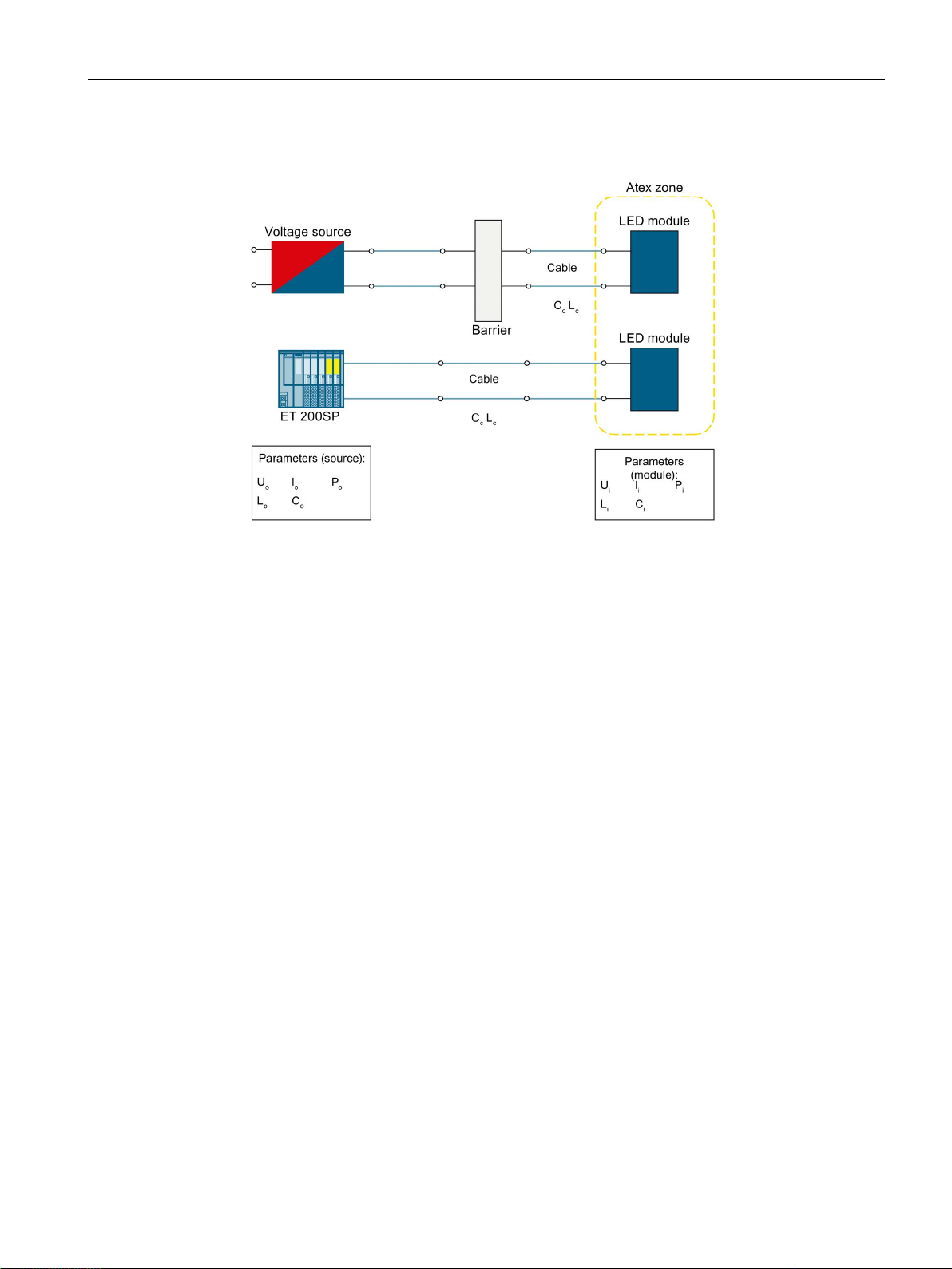
ATEX for intrinsically safe circuits
Basic representation of the use of the 24 V LED modules for intrinsic safety
Please note:
U
≤ U
0
i
I0 ≤ I
i
P0 ≤ Pi
C
≥ CC
0
L
≥ LC
0
● U
= maximum input voltage
i
● I
= maximum input current
i
● P
= maximum input power
i
● C
= maximum inner capacitance
i
● L
= maximum inner inductance
i
● U
= maximum output voltage
0
● I
= maximum output current
0
● P
= maximum output power
0
● C
= maximum outer capacitance
0
● L
= maximum outer inductance
0
SIRIUS ACT 3SU1 pushbuttons and signaling devices
System Manual, 08/2018, A5E03457306020A/RS-AK/010
27

ATEX for intrinsically safe circuits
SIRIUS ACT 3SU1 pushbuttons and signaling devices
28 System Manual, 08/2018, A5E03457306020A/RS-AK/010

4
4.1
Overview of the device range
3SU1 pushbuttons and indicator lights
SIRIUS ACT pushbuttons and indicator lights
3SU10 actuating and
signaling elements
3SU11 complete units1)
3SU12 compact units1)
3SU14 modules
without holder
3SU15 modules with
holder
3SU18 enclosures
3SU18..-3 two-hand
operation consoles
Description
• Pushbuttons
• Mushroom pushbuttons
• EMERGENCY STOP
mushroom pushbuttons
• Sensor switches
• Selector switches
• Twin pushbuttons
• Key-operated switches
• Indicator lights
• Indicator lights with "traffic
light" LED
• Illuminated pushbuttons
• ID key-operated switches
• Stop pushbuttons
• Toggle switches
• Coordinate switches
• Potentiometers
• USB adapters (3SU19)
• RJ45 adapters (3SU19)
• Contact modules
• LED modules
• LED test modules
• AS-Interface modul
e (front plate
mounting)
• AS-
Interface module
(base mounting)
• IO-Link
• Support terminal
• ID key module
• Unequipped
enclosures with
1, 2, 3, 4 or 6
command points
• EMERGENCY
STOP enclosures
• Enclosures with 1,
2 or 3 command
points
pre-equipped
• Palm pushbuttons
• Customized
enclosures on
request
• Two-hand operation
consoles including
EMERGENCY STOP
and two mushroom
pushbuttons
• Additional command
devices can be
mounted
SIRIUS ACT 3SU1 pushbuttons and signaling devices
System Manual, 08/2018, A5E03457306020A/RS-AK/010
29

Overview
SIRIUS ACT pushbuttons and indicator lights
3SU10 actuating and
signaling elements
3SU11 complete units1)
3SU12 compact units1)
3SU14 modules
without holder
3SU15 modules with
holder
3SU18 enclosures
3SU18..-3 two-hand
operation consoles
Version
Installation /
Connection
Degree of
protection
4.1 Overview of the device range
Front ring / Collar:
• Metal / Metal
• Metal, matte / Metal
• Metal, matte / Plastic
• Plastic / Plastic
• One-person installation
without special tools
• Modular equipping of the
actuating elements with
contact and/or LED
modules
• Screw terminal, spring-
loaded terminal, solder pin
connection
• IP66 / IP67 / IP692)
(plastic / metal)
• Plastic, black • Plastic
• Metal
• Front plate
mounting
• Base mounting
• Mounting on
printed-circuit
boards
• Screw terminals
• Spring-loaded
terminals
• Solder pin
connections
• Push-in for AS-I
• Insulation piercing
method for AS-I
Enclosure: IP40
Connecting terminals:
IP20
• Vertical /
Horizontal
• AS-I adapter M12
• AS-I cable gland
with insulation
piercing method
• Circular cable
glands
• Circular cable
glands with AS-I
cable entry
• Enclosure cover
monitoring
IP66 / IP67 / IP69
(plastic / metal)
• Plastic
• Metal
• Can be mounted on a
wall, stand, or directly
within the system
IP66
(plastic / metal)
SIRIUS ACT 3SU1 pushbuttons and signaling devices
30 System Manual, 08/2018, A5E03457306020A/RS-AK/010
 Loading...