

Siemens SIRIUS 3RW52 User Manual

___________________
___________________
___________________
___________________
___________________
___________________
___________________
___________________
___________________
___________________
___________________
___________________
___________________
___________________
Industrial Controls
Soft starters and solid-state
switching devices
SIRIUS 3RW52 Soft Starter
Manual
01/2019
A5E35630451002A/RS
Description
1
Safety information
2
Mounting and dismantling
3
Wiring
4
Parameter assignment
5
Commissioning
6
Functions
7
Messages and diagnostics
8
Maintenance and servicing
9
Technical specifications
10
Dimension drawings
11
Circuit diagrams
12
Example circuits
A
Third-party software
B
-AD/004
Siemens AG
Division Digital Factory
Postfach 48 48
90026 NÜRNBERG
GERMANY
A5E35630451002A/RS-AD/004
Ⓟ
Copyright © Siemens AG 2018.
All rights reserved
DANGER
indicates that death or severe personal injury will result if proper precautions are not taken.
WARNING
indicates that death or severe personal injury may result if proper precautions are not taken.
CAUTION
indicates that minor personal injury can result if proper precautions are not taken.
NOTICE
indicates that property damage can result if proper precautions are not taken.
WARNING
Siemens products may only be used for the applications described in the catalog and in the relevant technical
ambient conditions must be complied with. The information in the relevant documentation must be observed.
Legal information
Warning notice system
This manual contains notices you have to observe in order to ensure your personal safety, as well as to prevent
damage to property. The notices referring to your personal safety are highlighted in the manual by a safety alert
symbol, notices referring only to property damage have no safety alert symbol. These notices shown below are
graded according to the degree of danger.
If more than one degree of danger is present, the warning notice representing the highest degree of danger will
be used. A notice warning of injury to persons with a safety alert symbol may also include a warning relating to
property damage.
Qualified Personnel
The product/system described in this documentation may be operated only by personnel qualified for the specific
task in accordance with the relevant documentation, in particular its warning notices and safety instructions.
Qualified personnel are those who, based on their training and experience, are capable of identifying risks and
avoiding potential hazards when working with these products/systems.
Proper use of Siemens products
Note the following:
documentation. If products and components from other manufacturers are used, these must be recommended
or approved by Siemens. Proper transport, storage, installation, assembly, commissioning, operation and
maintenance are required to ensure that the products operate safely and without any problems. The permissible
Trademarks
All names identified by ® are registered trademarks of Siemens AG. The remaining trademarks in this publication
may be trademarks whose use by third parties for their own purposes could violate the rights of the owner.
Disclaimer of Liability
We have reviewed the contents of this publication to ensure consistency with the hardware and software
described. Since variance cannot be precluded entirely, we cannot guarantee full consistency. However, the
information in this publication is reviewed regularly and any necessary corrections are included in subsequent
editions.
01/2019 Subject to change

Table of contents
1 Description .............................................................................................................................................. 7
1.1 Target group ............................................................................................................................. 7
1.2 Device design ........................................................................................................................... 8
1.3 Operating principle .................................................................................................................... 9
1.4 Interaction interfaces............................................................................................................... 11
1.5 Operating modes and master control function ........................................................................ 12
1.6 Device versions ....................................................................................................................... 14
1.7 Areas of application / load types ............................................................................................. 16
1.8 Selection of the soft starter using the Simulation Tool for Soft Starters ................................. 17
1.9 Structure of the article number ............................................................................................... 18
1.10 Accessories ............................................................................................................................. 20
1.10.1 Accessories for 3RW52 soft starter ........................................................................................ 20
1.10.2 3RW5 communication module ................................................................................................ 22
1.10.3 SIRIUS Soft Starter ES (TIA Portal) ....................................................................................... 23
1.10.4 3RW5 HMI .............................................................................................................................. 24
1.11 Additional documentation ....................................................................................................... 27
1.12 Siemens Industry Online Support ........................................................................................... 29
1.13 Support Request ..................................................................................................................... 31
1.14 Siemens Industry Online Support app .................................................................................... 31
2 Safety information ................................................................................................................................. 33
2.1 ESD Guidelines ....................................................................................................................... 33
2.2 Reactive power compensation ................................................................................................ 35
2.3 Electromagnetic compatibility (EMC) according to IEC 60947-4-1 ........................................ 35
2.4 Security information ................................................................................................................ 35
2.5 Recycling and disposal ........................................................................................................... 36
3 Mounting and dismantling ..................................................................................................................... 37
3.1 Installing the 3RW52 soft starter ............................................................................................. 37
3.2 Mounting the fan cover ........................................................................................................... 38
3.3 Mounting the 3RW52 soft starter on a level surface ............................................................... 40
3.4 Installing / mounting / removing 3RW5 HMI ........................................................................... 42
3.4.1 Installing the Standard 3RW5 HMI in 3RW52 soft starter ...................................................... 42
3.4.2 Removing Standard 3RW5 HMI ............................................................................................. 43
3.4.3 Installing the High Feature 3RW5 HMI in the 3RW52 soft starter .......................................... 44
3.4.4 Removing the High Feature 3RW5 HMI ................................................................................. 45
SIRIUS 3RW52 Soft Starter
Manual, 01/2019, A5E35630451002A/RS-AD/004
3

Table of contents
3.4.5 Installing the Standard 3RW5 HMI into the control cabinet door ........................................... 46
3.4.6 Installing the High Feature 3RW5 HMI in the control cabinet door ........................................ 49
3.4.7 Installing the Standard 3RW5 HMI on a flat surface .............................................................. 53
3.4.8 Installing the High Feature 3RW5 HMI on a flat surface........................................................ 55
3.4.9 Cut out the hinged cover for 3RW5 HMI ................................................................................ 57
3.4.10 Replacing the hinged cover of the 3RW52 soft starter .......................................................... 58
4 Wiring ................................................................................................................................................... 59
4.1 Connections ........................................................................................................................... 59
4.1.1 Overview of all connections ................................................................................................... 59
4.1.2 State diagrams of the inputs and outputs .............................................................................. 61
4.2 Connecting the 3RW52 soft starter ........................................................................................ 63
4.3 Connect the 3RW52 soft starter to the main circuit connection (line side / motor side) ........ 64
4.4 Mounting terminal covers on main circuit connections .......................................................... 66
4.5 Replacing the terminals on size 2 devices ............................................................................. 67
4.6 Connecting the control terminals (screw terminals) ............................................................... 69
4.7 Disconnecting the control current form the screw-type terminals .......................................... 70
4.8 Connecting the control terminals (spring-type terminals) ...................................................... 71
4.9 Disconnecting the control current from the spring-loaded terminals ..................................... 72
4.10 Replacing the control terminals .............................................................................................. 73
4.11 Installing the cover for the control cable duct ........................................................................ 75
4.12 Removing the cover of the control cable duct ........................................................................ 76
5 Parameter assignment .......................................................................................................................... 77
5.1 Setting elements on the 3RW52 soft starter .......................................................................... 77
5.2 Overview of parameters ......................................................................................................... 80
5.3 Suggested settings ................................................................................................................ 81
5.4 Parameterizing the 3RW52 soft starter .................................................................................. 82
5.5 Setting RESET MODE and Soft Torque ................................................................................ 83
5.6 RESET MODES ..................................................................................................................... 85
5.7 Parameterizing output 13 / 14 (output signal ON or RUN) .................................................... 86
6 Commissioning ..................................................................................................................................... 89
6.1 Commissioning the 3RW52 soft starter ................................................................................. 89
6.2 Sealing the 3RW52 soft starter .............................................................................................. 90
6.3 First commissioning of the High Feature 3RW5 HMI ............................................................. 91
7 Functions .............................................................................................................................................. 93
7.1 Soft starting ............................................................................................................................ 93
7.2 Current limiting function ......................................................................................................... 96
7.3 Soft stopping .......................................................................................................................... 98
SIRIUS 3RW52 Soft Starter
4 Manual, 01/2019, A5E35630451002A/RS-AD/004

Table of contents
7.4 Motor protection ...................................................................................................................... 99
7.4.1 Electronic motor overload protection ...................................................................................... 99
7.4.2 Thermistor motor protection with temperature sensor (optional) .......................................... 100
7.5 Intrinsic device protection ..................................................................................................... 101
7.6 Soft Torque ........................................................................................................................... 102
7.7 Additional parameters ........................................................................................................... 104
7.8 Standard 3RW5 HMI ............................................................................................................. 105
7.8.1 Design of the Standard 3RW5 HMI ...................................................................................... 105
7.8.2 Standard 3RW5 HMI menu ................................................................................................... 107
7.9 High Feature 3RW5 HMI....................................................................................................... 110
7.9.1 Design and operator controls of the High Feature 3RW5 HMI ............................................. 110
7.9.2 Main menu of the High Feature 3RW5 HMI with the 3RW52 soft starter ............................. 112
7.9.3 Parameterizing the High Feature 3RW5 HMI ....................................................................... 116
7.9.4 Monitoring ............................................................................................................................. 117
7.9.4.1 Monitoring the measured values of the 3RW52 soft starter with the High Feature
3RW5 HMI ............................................................................................................................ 117
7.9.4.2 Monitoring the process image of the 3RW52 soft starter with the High Feature 3RW5
HMI........................................................................................................................................ 118
7.9.5 Parameterizing analog output AQ via the High Feature 3RW5 HMI .................................... 119
7.9.6 Overview ............................................................................................................................... 121
7.9.7 Defining the local access protection (PIN) ............................................................................ 122
7.9.8 Micro SD card ....................................................................................................................... 124
8 Messages and diagnostics .................................................................................................................. 127
8.1 Diagnostics options ............................................................................................................... 127
8.2 LED display ........................................................................................................................... 128
8.2.1 Overview of the device LEDs of the 3RW52 soft starter ...................................................... 128
8.2.2 Status and error displays ...................................................................................................... 129
8.2.3 LED STATE / OVERLOAD ................................................................................................... 130
8.2.4 Overview of LEDs on Standard 3RW5 HMI .......................................................................... 131
8.2.5 Overview of LEDs on High Feature 3RW5 HMI ................................................................... 132
8.3 Warnings and remedial measures ........................................................................................ 133
8.4 Faults and remedial actions of the 3RW52 soft starter ......................................................... 134
8.5 Faults and remedial actions on the 3RW5 HMI High Feature .............................................. 138
8.6 RESET MODES .................................................................................................................... 139
8.7 Diagnostics of the 3RW52 soft starter with the 3RW5 HMI High Feature ............................ 140
8.8 Diagnostics of communication with the High Feature 3RW5 HMI ........................................ 142
8.9 Execute HMI diagnostics with the 3RW5 HMI High Feature ................................................ 142
8.10 Logbooks .............................................................................................................................. 143
9 Maintenance and servicing .................................................................................................................. 145
9.1 Maintenance and repairs ...................................................................................................... 145
9.2 User test ................................................................................................................................ 146
9.3 Firmware update ................................................................................................................... 149
SIRIUS 3RW52 Soft Starter
Manual, 01/2019, A5E35630451002A/RS-AD/004
5

Table of contents
9.4 Performing firmware update with micro SD card (3RW5 HMI High Feature) ...................... 150
9.5 Restore factory setting ......................................................................................................... 151
9.5.1 Restoring the factory settings via High Feature 3RW5 HMI ................................................ 152
9.5.2 Restoring the factory settings with the Master RESET button via 3RW5 HMI High
Feature ................................................................................................................................. 153
10 Technical specifications ....................................................................................................................... 155
10.1 Technical data in Siemens Industry Online Support ............................................................ 155
11 Dimension drawings ............................................................................................................................. 157
11.1 CAx data .............................................................................................................................. 157
12 Circuit diagrams ................................................................................................................................... 159
12.1 CAx data .............................................................................................................................. 159
A Example circuits ................................................................................................................................... 161
A.1 Main circuit connection ........................................................................................................ 161
A.1.1 Feeder assembly, type of coordination 1 fuseless............................................................... 161
A.1.2 Feeder assembly, type of coordination 1 with fuses ............................................................ 162
A.1.3 Feeder assembly, type of coordination 2 ............................................................................. 163
A.1.4 Inside-delta circuit ................................................................................................................ 164
A.2 Control circuit connection ..................................................................................................... 167
A.2.1 Control by pushbutton .......................................................................................................... 167
A.2.2 Control by switch .................................................................................................................. 168
A.2.3 Switching with the control supply voltage ............................................................................ 169
A.2.4 Control by PLC ..................................................................................................................... 171
A.2.5 Actuation of a line contactor ................................................................................................. 172
A.2.6 Wiring for remote RESET .................................................................................................... 174
A.2.7 Connecting the temperature sensor .................................................................................... 175
A.2.8 Connecting the evaluation unit to the analog output............................................................ 176
A.3 Special applications ............................................................................................................. 177
A.3.1 Controlling a motor with a magnetic parking brake .............................................................. 177
A.3.2 EMERGENCY STOP shutdown to SIL 1 or PL c with a 3SK1 safety relay ......................... 179
A.3.2.1 Wiring of the 3SK1 safety relay SIL 1 with line contactor .................................................... 181
A.3.2.2 Wiring of the 3SK1 safety relay SIL 1 without line contactor ............................................... 182
A.3.3 EMERGENCY STOP shutdown to SIL 3 or PL e with a 3SK1 safety relay......................... 183
A.3.3.1 Wiring of the 3SK1 safety relay SIL 3 with line contactor .................................................... 185
A.3.3.2 Wiring of the 3SK1 safety relay SIL 3 without line contactor ............................................... 186
A.3.4 Contactor for emergency start ............................................................................................. 187
B Third-party software ............................................................................................................................. 189
B.1 Information about third-party software ................................................................................. 189
Glossary .............................................................................................................................................. 193
Index ................................................................................................................................................... 195
SIRIUS 3RW52 Soft Starter
6 Manual, 01/2019, A5E35630451002A/RS-AD/004

1
1.1 Target group
Target group
The manual is intended for everyone involved in the following tasks:
● Planning and configuring systems
● Installation
● Commissioning
● Service and maintenance
Requirements for use of 3RW5 soft starters
Basic knowledge of the following areas:
● General electrical engineering
● Drive technology
● Automation technology
● Handling the automation system and the software used
SIRIUS 3RW52 Soft Starter
Manual, 01/2019, A5E35630451002A/RS-AD/004
7
Description
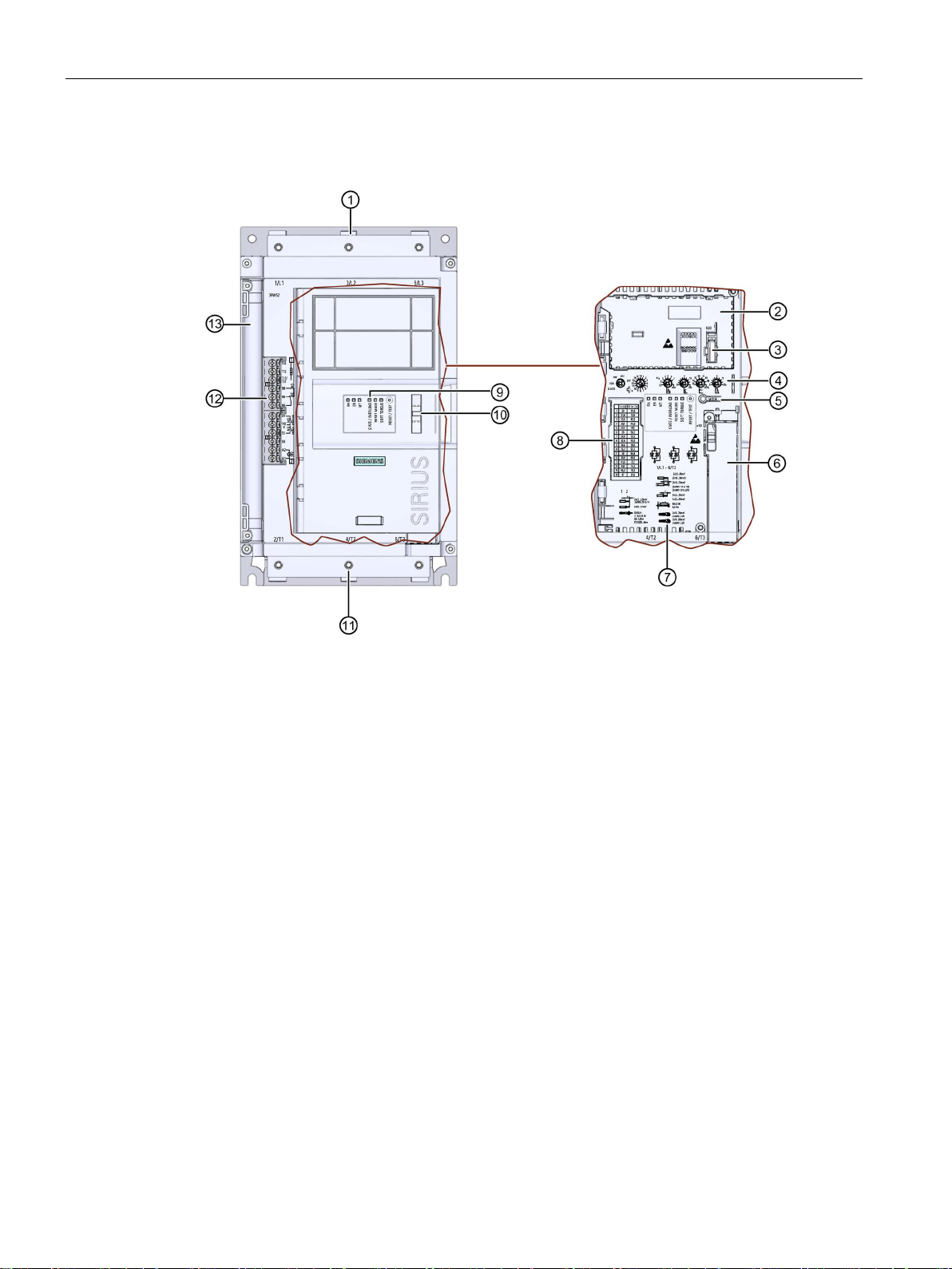
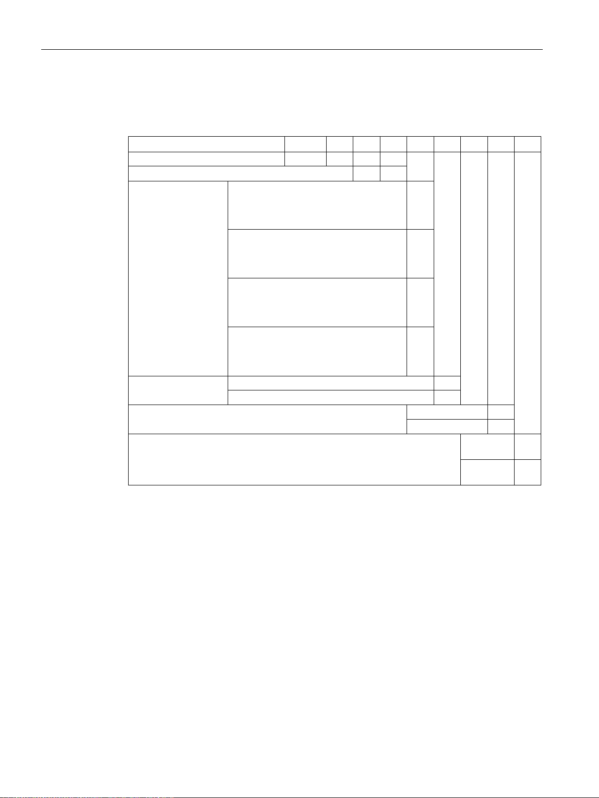
①
Main circuit connection (mains supply)
②
Slot for 3RW5 HMI Standard or 3RW5 HMI High Feature (accessories)
③
Interface for 3RW5 HMI Standard or 3RW5 HMI High Feature (accessories)
④
Setting elements for parameter assignment
⑤
MODE key
⑥
Slot for 3RW5 communication module (accessory)
⑦
Connectable conductor cross sections
⑧
Scale of the setting element Ie
⑨
Diagnostics LEDs and RESET key
⑩
Eye for lead seal
⑪
Main circuit connection (motor)
⑫
Control terminals (inputs / outputs)
⑬
Control cable duct
1.2 Device design
1.2 Device design
SIRIUS 3RW52 Soft Starter
8 Manual, 01/2019, A5E35630451002A/RS-AD/004

Description
①
(t5-t4)
②
Voltage
t6
Motor at standstill
t1
Motor start-up with set starting voltage US
US
Set starting voltage
t2
Rated speed ne achieved
Ue
Rated operational voltage
(t3-t1)
switched off
1.3 Operating principle
1.3 Operating principle
Soft starters are used to start three-phase induction motors with reduced torque and reduced
starting current.
The 3RW52 soft starter starts the motor as soon as the switch-on command is issued (t
During the ramp-up time (t
to t3), the current is conducted via power semiconductors which
1
).
1
start the motor up smoothly.
The 3RW52 soft starter features internal run-up recognition. If it detects that the motor has
reached its rated operating speed before the ramp-up time expires, the motor voltage is
immediately increased to 100 % of the line voltage (t
). The internal bypass contacts close
2
and the power semiconductors are bypassed. The 3RW52 soft starter is then in bypass
operation.
Coast-down to zero speed is activated when the switch-on command is cancelled (t
) and
4
the motor is shut down. The power semiconductors also ensure that the motor coasts down
smoothly to a stop. The power supply to the motor is maintained (t
ramp-down time is reached (t
to a standstill (t
).
6
to t5). It may take longer for the motor to actually coast down
4
) until the end of the
5
Speed t5 End of the set ramp-down time
t3 End of the set ramp-up time
t
Switch-on command is cancelled, motor is
4
SIRIUS 3RW52 Soft Starter
Manual, 01/2019, A5E35630451002A/RS-AD/004
ne Rated motor speed
9

Description
1.3 Operating principle
Functions
● Soft starting with parameterizable starting voltage and starting ramp time
● Soft stopping with parameterizable ramp-down time
● Parameterizable current limiting function
● Soft torque for smooth ramp-up and ramp-down (avoiding torque peaks by means of
torque limitation)
● Integrated motor overload protection with adjustable trip class (Off, Class 10A, 10E, 20E)
● The intrinsic device protection protects the 3RW52 soft starter against overload.
● Ramp-up detection
● Extended operating and diagnostic functions provided by the optional 3RW5 HMI
Standard or 3RW5 HMI High-Feature
● Connection to motor in inline circuit or inside-delta circuit
● Adjustable RESET MODE (manual RESET, remote RESET, auto RESET) for the
functions of motor protection
● Extended full motor protection via optional thermistor motor protection for connection of a
temperature switch (e.g. Thermoclick) or a thermistor (e.g. PTC type A) (alternative to
analog output)
● Optional analog output for output of a measured value (alternative to thermistor motor
protection)
● Optional 3RW5 communication module for integration into bus systems
● Firmware updates upgrade the firmware of the respective device.
Further details can be found in Chapter Functions (Page 93).
SIRIUS 3RW52 Soft Starter
10 Manual, 01/2019, A5E35630451002A/RS-AD/004
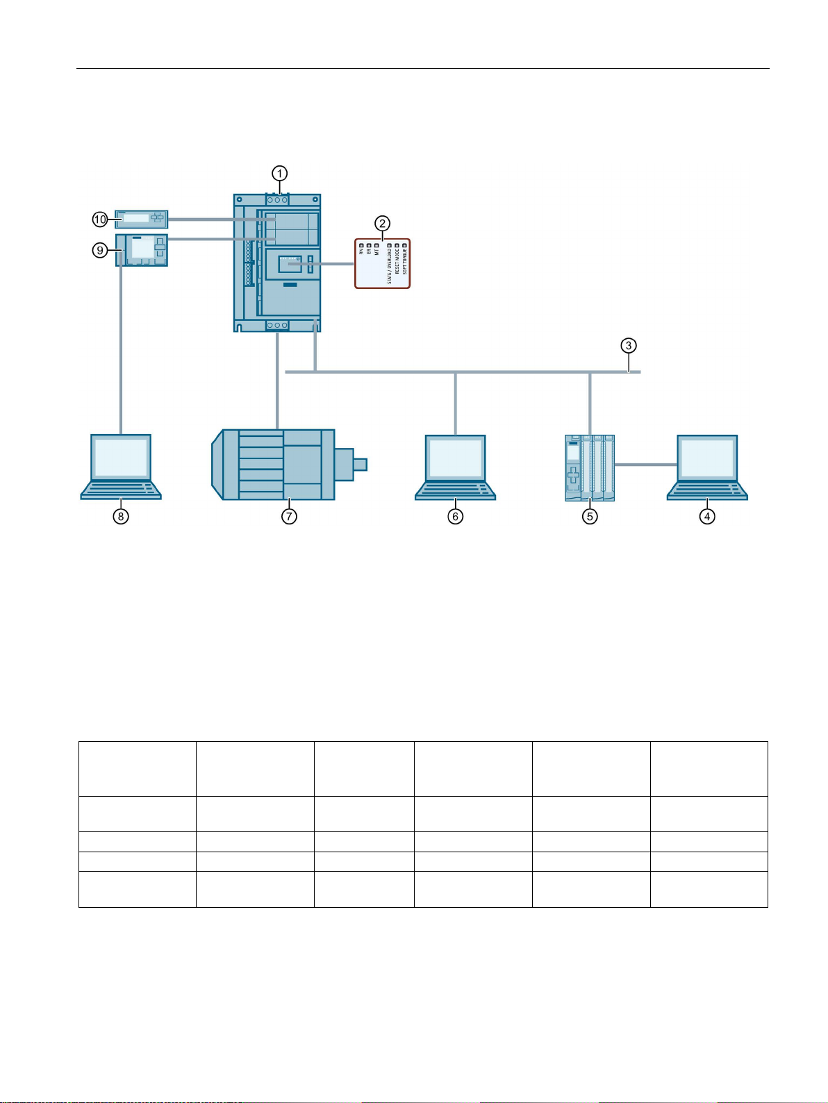
Description
①
SIRIUS 3RW52 soft starter
②
LED display on 3RW52 soft starter
③
Fieldbus (via optional communication module)
④
PC or programming device with configuring software of controller (e.g. STEP 7)
⑤
Programmable logic controller (e.g. SIMATIC S7-1500)
⑥
PC with SIRIUS Soft Starter ES (TIA Portal) Premium via 3RW5 communication module
⑦
Motor
⑧
PC with SIRIUS Soft Starter ES (TIA Portal) via local interface on 3RW5 HMI High Feature
⑨
3RW5 HMI High Feature (accessories)
⑩
3RW5 HMI Standard (accessories)
3RW5 HMI
High Feature
3RW5 HMI
Standard
SIRIUS Soft
Starter ES
(TIA Portal)1)
Fieldbus via 3RW5
communication
module
3RW52 soft starter
program)
Diagnostics ✓ ✓ ✓ ✓
LEDs
Control ✓ ✓ ✓ ✓
Via input IN
1)
2)
3)
Station address for PROFIBUS is adjustable.
1.4 Interaction interfaces
1.4 Interaction interfaces
Monitoring ✓ ✓ ✓ ✓ (via user
Parameter
assignment
Via local interface on 3RW5 HMI High Feature or via 3RW5 communication module.
Analog output (for device version with analog output only) and ON / RUN relay output parameterizable.
2), 3)
-
-3) - - Setting elements
LEDs
SIRIUS 3RW52 Soft Starter
Manual, 01/2019, A5E35630451002A/RS-AD/004
11
Description
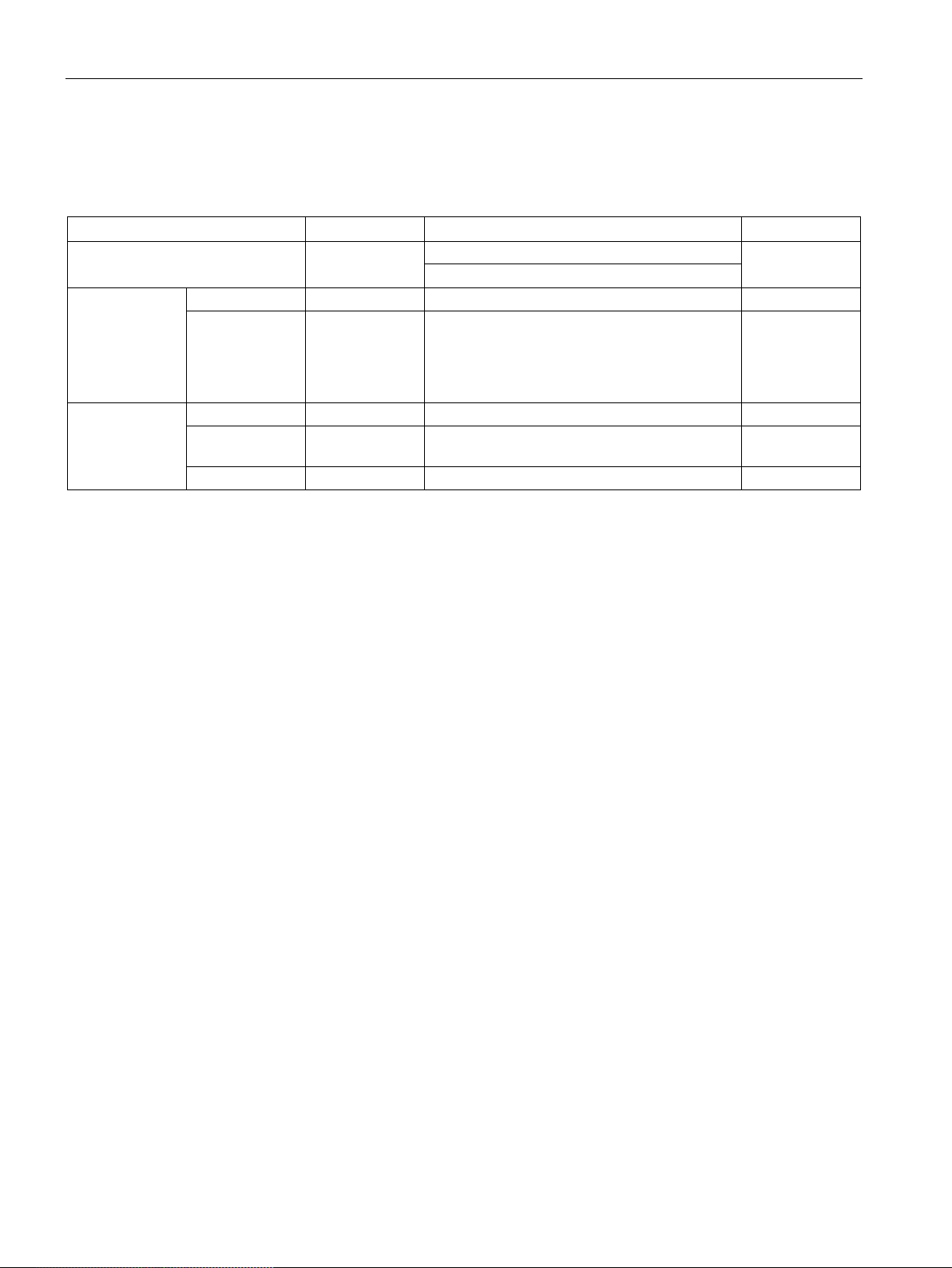
Mode
Control source
Control of the 3RW5 soft starter
Priority
PROFINET and PROFIBUS: PLC controls
module)
- - Connection abort
↓
Input controlled
Digital inputs
Input actions control
↓
controls
PC controlled
Local interface
SIRIUS Soft Starter ES (TIA Portal) controls
Highest
1.5 Operating modes and master control function
1.5 Operating modes and master control function
The following modes are available (in ascending order of priority):
Automatic Fieldbus
Manual
operation bus
(depending on
the 3RW5
communication
Manual
operation local
PC controlled Fieldbus SIRIUS Soft Starter ES (TIA Portal) Premium
3RW5 HMI
3RW5 HMI 3RW5 HMI controls ↓
If the connection to the control source is aborted, the control priority automatically switches
back to the lowest priority of the current mode.
Sets the operating mode
A higher-priority mode can actively take over as master control from a lower-priority mode at
any time; the reverse is not possible.
The master control function can only be returned to the mode with the lowest priority. Control
sources with higher priority must take the master control function from the mode with the
lowest priority.
Lowest
Modbus: Modbus client (e.g. PLC) controls
↓
controls
A mode with lower priority can only take the master control function back while the motor is
switched off.
The mode with higher priority takes over or receives the master control function from the
current mode in the following ways:
● The mode with higher priority actively takes over the master control function:
– 3RW5 HMI: With the action "LOCAL / REMOTE"
– SIRIUS Soft Starter ES (TIA Portal)
● The digital inputs receive the control priority from an operating mode with lower priority
via the following options:
– Via the "Manual operation local - input controlled" bit in the process image output
(PIQ) or in the data table "process image output (PIQ)" (depending on the 3RW5
communication module). You will find more information on the process images and
data tables in the manual for the 3RW5 communication module in question.
– SIRIUS Soft Starter ES (TIA Portal) (depending on the 3RW5 communication module)
SIRIUS 3RW52 Soft Starter
12 Manual, 01/2019, A5E35630451002A/RS-AD/004

Description
1.5 Operating modes and master control function
The mode with the lowest priority receives or takes over the master control function from the
current mode in the following ways:
● The mode with higher priority actively returns the master control function:
– 3RW5 HMI: With the action "LOCAL / REMOTE"
– SIRIUS Soft Starter ES (TIA Portal)
● With control priority of the digital inputs or in the event of a connection abort, the
operating mode with the lower priority can actively retrieve the control priority:
– Via the "Manual operation local - input controlled" bit in the process image output
(PIQ) or in the data table "process image output (PIQ)" (depending on the 3RW5
communication module). You will find more information on the process images and
data tables in the manual for the 3RW5 communication module in question.
– SIRIUS Soft Starter ES (TIA Portal) (depending on the 3RW5 communication module)
SIRIUS 3RW52 Soft Starter
Manual, 01/2019, A5E35630451002A/RS-AD/004
13
Description
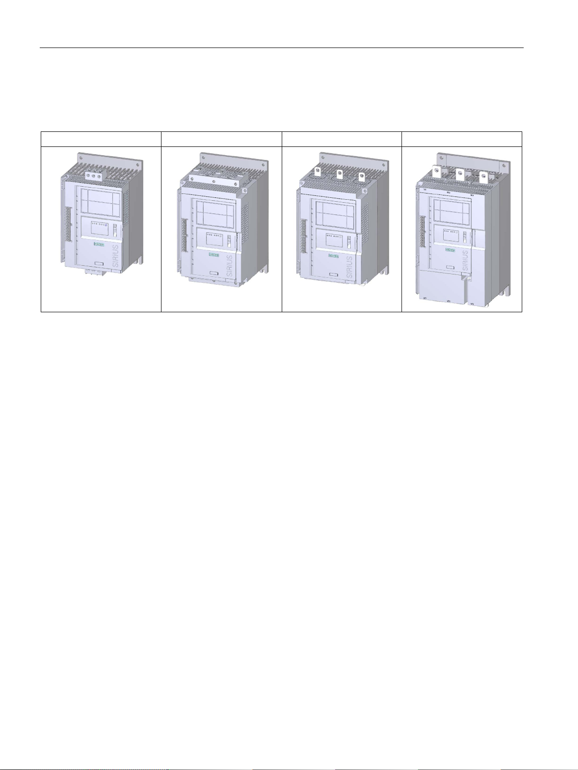
Size 1
Size 2
Size 3
Size 4
1.6 Device versions
1.6 Device versions
SIRIUS 3RW52 Soft Starter
14 Manual, 01/2019, A5E35630451002A/RS-AD/004
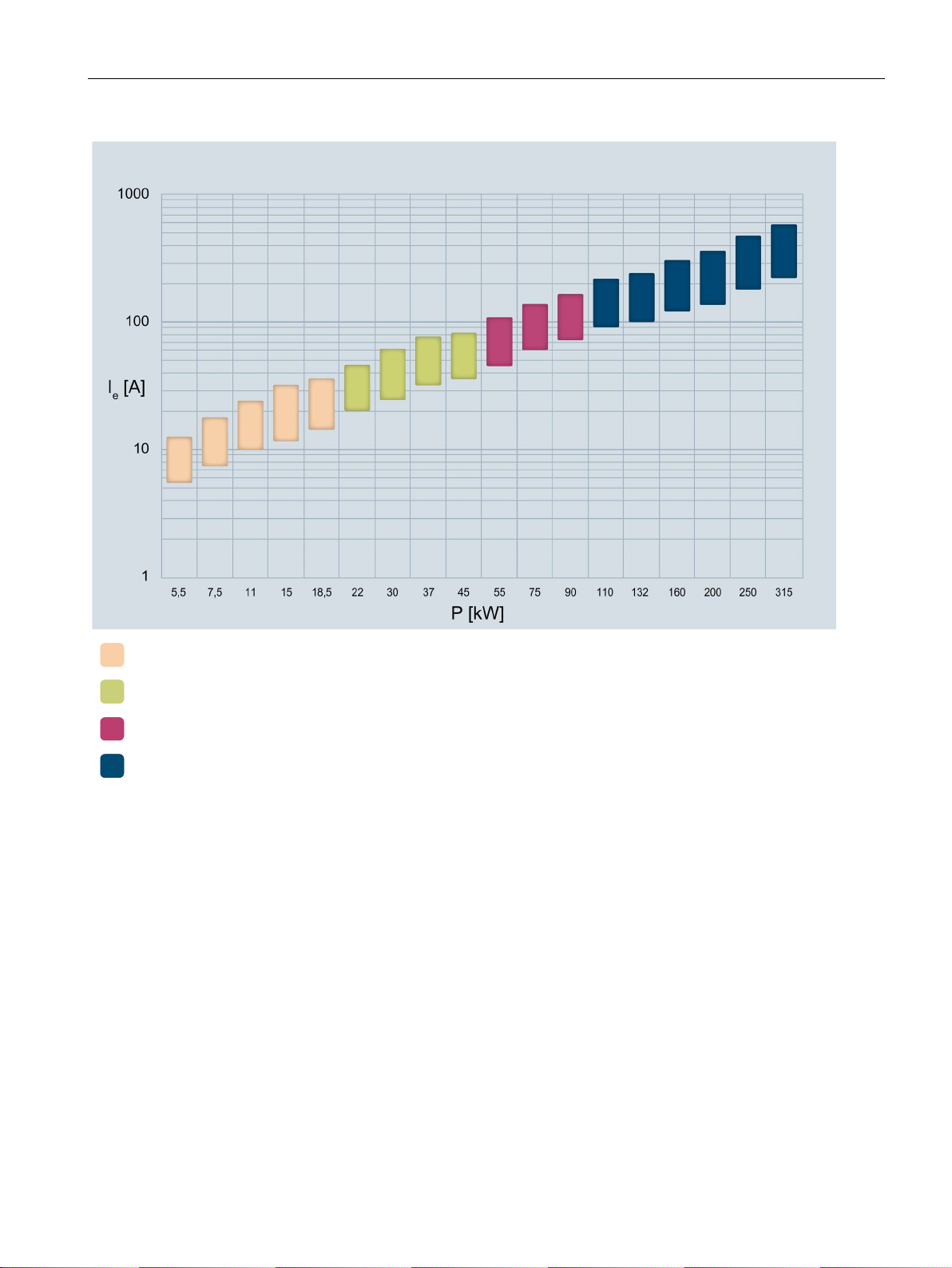
Description
Ie
Rated operational current
P
Rated power
The stated power ratings apply to a rated operational voltage of Ue = 400 V in a standard circuit.
1.6 Device versions
Size 1
Size 2
Size 3
Size 4
SIRIUS 3RW52 Soft Starter
Manual, 01/2019, A5E35630451002A/RS-AD/004
15
Description
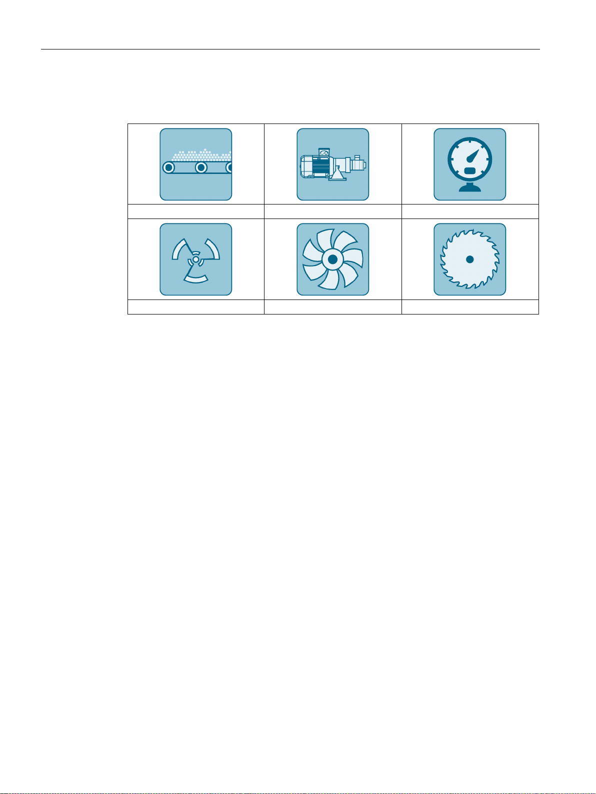
Conveyor belts
Pumps
Compressors
1.7 Areas of application / load types
1.7 Areas of application / load types
Agitators Fans Saws
Starting of a motor causes a rapid change in the load current. The resulting torque impulses
place severe stresses on the mechanical parts of a machine or plant. Moreover, voltage dips
can occur in the power supply system which can have a negative influence on other devices:
● Flicker in lights
● Influence on computer systems
● Contactors and relays dropping out
The 3RW52 soft starter controls the voltage continuously. The torque and the current are
thus also increased continuously. The power supply system is safeguarded against peak
loads and the drive train is protected against damage:
● Smooth starting / stopping, e.g. for conveyor belts
● No pressure surges, e.g. for pumps
● Increased service life of the pipe system, e.g. for compressors
● Reduced starting current, e.g. for agitators
● Reduced stress on gearbox and V belt, e.g. for saws
SIRIUS 3RW52 Soft Starter
16 Manual, 01/2019, A5E35630451002A/RS-AD/004
Description
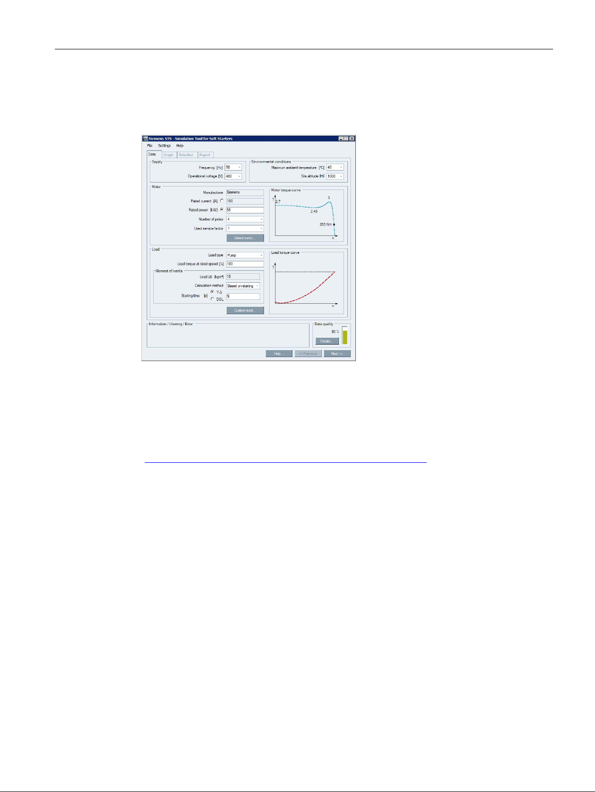
1.8 Selection of the soft starter using the Simulation Tool for Soft Starters
1.8 Selection of the soft starter using the Simulation Tool for Soft
Starters
The soft starter can be configured with the STS (Simulation Tool for Soft Starters) software.
The STS suggests suitable soft starters for the respective application based on the entered
motor and load data and application requirements, as well as providing information on the
parameterization.
The Simulation Tool for Soft Starters (STS) can be downloaded from the Internet
(https://support.industry.siemens.com/cs/ww/en/view/101494917
).
SIRIUS 3RW52 Soft Starter
Manual, 01/2019, A5E35630451002A/RS-AD/004
17
Description
Digit of the article number
1st-4th
5th
6th
7th
8th
9th
10th
11th
12th
SIRIUS 3RW soft starter
3RW5
2
Analog output
A
24 V AC / DC
0
110 V - 250 V AC
1
480 V AC
600 V AC
*see table below.
1.9 Structure of the article number
1.9 Structure of the article number
C
Size and rated operational current Ie of the soft starter x* x**
Connection system
Control terminals with
Rated control supply voltage US
• Applies to sizes 1 / 2
• Main circuit: Screw terminals
• Control circuit: Screw terminals
• Applies to sizes 3 / 4
• Main circuit: Bus connection
• Control circuit: Spring-type terminals
• Applies to sizes 1 / 2
• Main circuit: Screw terminals
• Control circuit: Spring-type terminals
• Applies to sizes 3 / 4
• Main circuit: Bus connection
• Control circuit: Screw terminals
Thermistor motor protection T
1
2
3
6
Rated operational voltage Ue 200 -
200 -
4
5
SIRIUS 3RW52 Soft Starter
18 Manual, 01/2019, A5E35630451002A/RS-AD/004

Description
Ie = 13 A
Pe = 5.5 kW
1
3
Ie = 25 A
Pe = 11 kW
1
5
Ie = 32 A
Pe = 15 kW
1
6
Ie = 38 A
Pe = 18.5 kW
1
7
Ie = 47 A
Pe = 22 kW
2
4
Ie = 63 A
Pe = 30 kW
2
5
Ie = 77 A
Pe = 37 kW
2
6
Ie = 93 A
Pe = 45 kW
2
7
Ie = 113 A
Pe = 55 kW
3
4
Ie = 143 A
Pe = 75 kW
3
5
Ie = 171 A
Pe = 90 kW
3
6
Ie = 210 A
Pe = 110 kW
4
3
Ie = 250 A
Pe = 132 kW
4
4
Ie = 315 A
Pe = 160 kW
4
5
Ie = 370 A
Pe = 200 kW
4
6
Ie = 470 A
Pe = 250 kW
4
7
Ie = 570 A
Pe = 315 kW
4
8
1.9 Structure of the article number
Table 1- 1 Size and rated operational current at Ue = 400 V and TU = 40°C and in a standard circuit
Rated operational current Ie of
the soft starter
Size 1
Ie = 18 A Pe = 7.5 kW 1 4
Size 2
Size 3
Size 4
Rated operating power Pe of
the soft starter
x* x**
SIRIUS 3RW52 Soft Starter
Manual, 01/2019, A5E35630451002A/RS-AD/004
19
Description
1.10 Accessories
1.10 Accessories
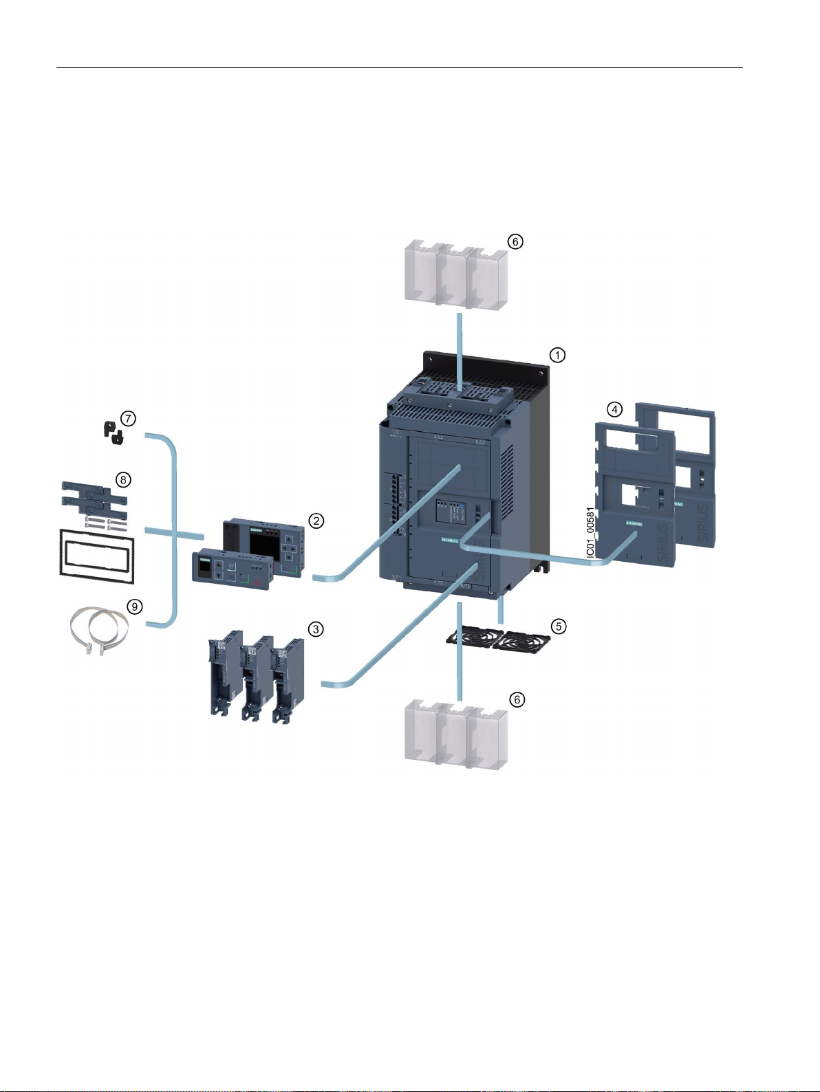
1.10.1 Accessories for 3RW52 soft starter
SIRIUS 3RW52 Soft Starter
20 Manual, 01/2019, A5E35630451002A/RS-AD/004

Description
①
3RW52 soft starter
②
③
④
⑤
⑥
⑦
Push-in lugs for wall mounting (3ZY1311-0AA00)
⑧
IP65 door mounting kit (3RW5980-0HD00)
⑨
1.10 Accessories
3RW5 HMI modules
• 3RW5 HMI Standard (3RW5980-0HS00)
• 3RW5 HMI High Feature (3RW5980-0HF00)
3RW5 communication modules
• PROFIBUS (3RW5980-0CP00)
• PROFINET Standard (3RW5980-0CS00)
• Modbus TCP (3RW5980-0CT00)
Hinged cover
• Hinged cover with cutout for 3RW5 HMI Standard (3RW5950-0GL40)
• Hinged cover with cutout for 3RW5 HMI High Feature (3RW5950-0GL30)
Fan cover:
• Sizes 1, 2 and 3 (3RW5983-0FC00)
• Size 4 (3RW5984-0FC00)
Terminal cover, top and bottom:
• Sizes 2 and 3 (3RW5983-0TC20)
• Size 4 (3RW5984-0TC20)
HMI connecting cable:
• 0.1 m (3UF7931-0AA00-0)
• 0.5 m (3UF7932-0BA00-0)
• 1 m (3UF7937-0BA00-0)
• 2.5 m (3UF7933-0BA00-0)
• 5 m (3RW5980-0HC60)
SIRIUS 3RW52 Soft Starter
Manual, 01/2019, A5E35630451002A/RS-AD/004
21
Description
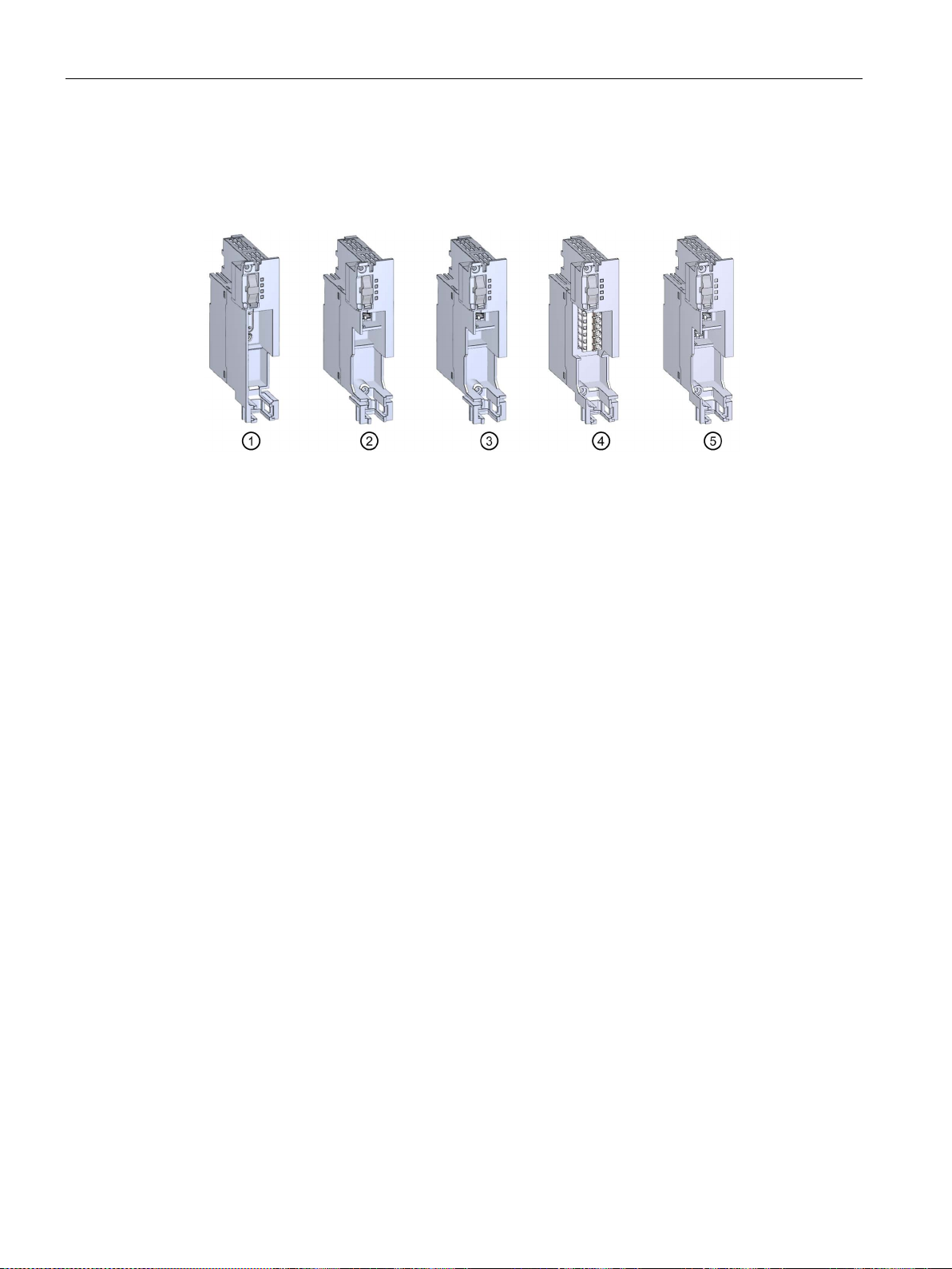
①
3RW5 PROFIBUS communication module
②
3RW5 PROFINET Standard communication module
③
3RW5 Modbus TCP communication module
④
3RW5 Modbus RTU communication module
⑤
3RW5 Ethernet IP communication module
1.10 Accessories
1.10.2 3RW5 communication module
The following 3RW5 communication modules are available for integration of the 3RW52 soft
starters in fieldbus systems:
Integration into the automation software
The 3RW52 soft starter can be integrated in an automation software, e.g. STEP 7
(TIA Portal) via GSD / GSDML or HSP.
You will find further information on operation of the 3RW5 communication module in the
equipment manual for the 3RW5 communication module in question.
SIRIUS 3RW52 Soft Starter
22 Manual, 01/2019, A5E35630451002A/RS-AD/004
Description
1.10 Accessories
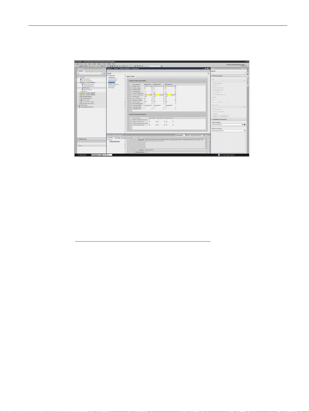
1.10.3 SIRIUS Soft Starter ES (TIA Portal)
SIRIUS Soft Starter ES (TIA Portal) is the central software for configuring, commissioning,
operation, and diagnostics of 3RW5 soft starters.
You connect your PC / programming device to the soft starter via the local interface on the
optional 3RW5 HMI High Feature.
By displaying all operating data, service data and diagnostics data, SIRIUS Soft Starter ES
supplies reliable information, helping to avoid faults, or quickly locating and eliminating them
if they occur.
With the premium license, soft starters can also be parameterized and diagnosed from a
central location via PROFIBUS DP or PROFINET on the optional communication module.
SIRIUS Soft Starter ES (TIA Portal) can be downloaded from the Internet
(https://support.industry.siemens.com/cs/ww/en/ps/24231/dl
).
SIRIUS 3RW52 Soft Starter
Manual, 01/2019, A5E35630451002A/RS-AD/004
23
Description
1.10 Accessories
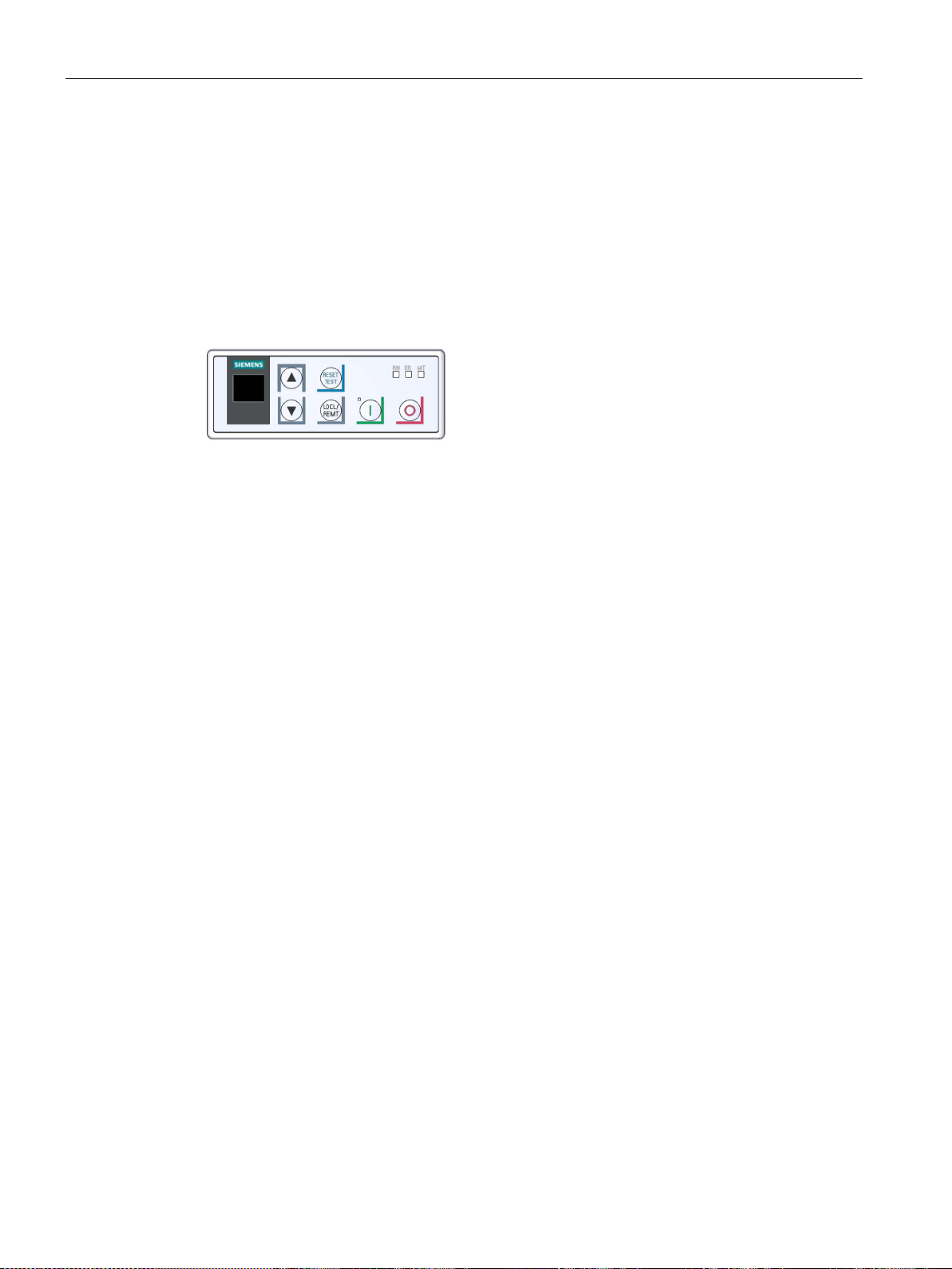
1.10.4 3RW5 HMI
3RW5 HMI Standard
The 3RW5 HMI Standard can be used to monitor and control (motor ON / OFF) the 3RW52
soft starter and acknowledge faults. The 3RW5 HMI Standard can either be installed in the
3RW52 soft starter or in the control cabinet door (using accessories) or mounted on a wall
(using accessories). It features an LCD with red display illumination and LEDs for status
display, as well as function and control keys.
Functions
● Any changes of setting elements will be indicated immediately in the display.
● Error diagnostics are output as error numbers (Faults and remedial actions of the 3RW52
soft starter (Page 134)).
● Acknowledgment of faults and execution of user tests via the RESET / TEST key
● Starting and stopping the motor via control keys
● Mode change with the LOCAL / REMOTE key.
● Setting the PROFIBUS station address.
● Display of the device LEDs of the 3RW5 HMI Standard shows the messages of the
following devices:
– 3RW52 soft starter
– 3RW5 HMI Standard
– Communication module (if there is one)
SIRIUS 3RW52 Soft Starter
24 Manual, 01/2019, A5E35630451002A/RS-AD/004
Description
1.10 Accessories
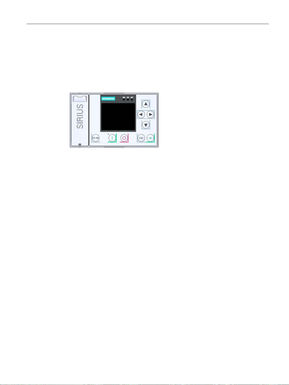
3RW5 HMI High Feature (HF)
The 3RW5 HMI High Feature can be used to parameterize, monitor and control (motor ON /
OFF) the 3RW52 soft starter. The HMI High Feature module can either be installed in the
3RW52 soft starter or in the control cabinet door (using accessories) or mounted on a wall
(using accessories). It can be connected to the SIRIUS Soft Starter ES software (TIA Portal)
via the local interface. It has a TFT color display, LEDs for displaying the system status as
well as function and control keys.
Functions
● Editable Favorites key F1 - F9
● Language selection
● Starting and stopping the motor via control keys
● Local interface
● Display of error diagnoses as plain-text messages
● Display of up to 5 measured values at the same time
● Analog output and ON / RUN relay output can be parameterized with the 3RW5 HMI High
Feature.
● Setting communication parameters of 3RW5 communication modules:
– PROFINET (device names and the IP parameters)
– PROFIBUS (station address)
– Modbus TCP (IP parameters)
– Modbus RTU (server address)
– Ethernet IP (IP parameters)
● Backup of parameterization data
SIRIUS 3RW52 Soft Starter
Manual, 01/2019, A5E35630451002A/RS-AD/004
25

Description
1.10 Accessories
● Display of the device LEDs of the 3RW5 HMI High Feature shows the messages of the
following devices:
– 3RW52 soft starter
– 3RW5 HMI High Feature
– Communication module (if there is one)
● Firmware update can be performed using the High Feature 3RW5 HMI and a memory
card for the following devices (Performing firmware update with micro SD card (3RW5
HMI High Feature) (Page 150)):
– 3RW52 soft starter
– 3RW5 HMI High Feature
– Communication module
SIRIUS 3RW52 Soft Starter
26 Manual, 01/2019, A5E35630451002A/RS-AD/004

Description
1.11 Additional documentation
1.11 Additional documentation
Manuals / online help
At this point, you will find further manuals and online help that may be of interest to you for
your automation system. They are available to download from the Internet free of charge.
You can create your own individual system documentation in mySupport.
● 3RW5 topic page (https://support.industry.siemens.com/cs/ww/en/view/109747404
● Equipment Manual for the 3RW52 soft starter
(https://support.industry.siemens.com/cs/ww/en/view/109753751
● Equipment Manual for the 3RW55 soft starter
(https://support.industry.siemens.com/cs/ww/en/view/109753752
● Equipment Manuals for the 3RW5 soft starter
(https://support.industry.siemens.com/cs/ww/en/ps/16212/man
● Equipment Manual for the 3RW5 PROFINET communication modules
(https://support.industry.siemens.com/cs/ww/en/view/109753754
● Equipment Manual for the 3RW5 PROFIBUS communication module
(https://support.industry.siemens.com/cs/ww/en/view/109753753
● Equipment Manual for the 3RW5 Modbus communication modules
(https://support.industry.siemens.com/cs/ww/en/view/109753755
● Equipment Manual for the 3RW5 Ethernet IP communication module
(https://support.industry.siemens.com/cs/ww/en/view/109758201
● Online help for SIRIUS Soft Starter ES (TIA Portal)
● Online help for STEP 7
● The EMC Directive 2014/30/EU in practice (http://www.siemens.com/emc-guideline
● Industrial Control Panels and Electronic Equipment of Industrial Machinery for North
America (http://www.siemens.com/UL508A
)
)
)
)
)
)
)
)
)
)
● Control Panels compliant with IEC Standards and European Directives
(http://www.siemens.com/iec60204
SIRIUS 3RW52 Soft Starter
Manual, 01/2019, A5E35630451002A/RS-AD/004
)
27

Description
1.11 Additional documentation
Interesting links
● FAQs for soft starters 3RW5
(https://support.industry.siemens.com/cs/ww/en/ps/16212/faq
● Downloads for soft starters 3RW5
(https://support.industry.siemens.com/cs/ww/en/ps/16212/dl
● Manuals in Siemens Industry Online Support
(https://support.industry.siemens.com/cs/ww/en/ps/man
● Product support for STEP 7 (TIA Portal)
(https://support.industry.siemens.com/cs/ww/en/ps/14672
● Further information on PROFINET
https://www.siemens.com/global/en/home/products/automation/industrial-
(
communication/profinet.html)
● SIMATIC Modbus/TCP - The easy way to interface SIMATIC controllers to multi-vendor
systems (
products/customized-software/Pages/default.aspx?tabcardname=simatic%20modbus/tcp)
● Premium Efficiency - Efficiency class IE3
http://w3.siemens.com/mcms/topics/en/application-
(
consulting/ie3ready/Pages/Default.aspx)
http://w3.siemens.com/mcms/human-machine-interface/en/customized-
)
)
)
)
SIRIUS 3RW52 Soft Starter
28 Manual, 01/2019, A5E35630451002A/RS-AD/004

Description
1.12 Siemens Industry Online Support
1.12 Siemens Industry Online Support
Information and service
At Siemens Industry Online Support you can obtain up-to-date information from our global
support database quickly and simply. To accompany our products and systems, we offer a
wealth of information and services that provide support in every phase of the lifecycle of your
machine or plant – from planning and implementation and commissioning, right through to
maintenance and modernization:
● Product support
● Application examples
● Services
● Forum
● mySupport
Link: Siemens Industry Online Support (https://support.industry.siemens.com/cs/de/en)
Product support
Here you will find all the information and comprehensive know-how for your product:
● FAQs
Our replies to frequently asked questions.
● Manuals/operating instructions
Read online or download, available as PDF or individually configurable.
● Certificates
Clearly sorted according to approving authority, type and country.
● Characteristics
For support in planning and configuring your system.
● Product announcements
The latest information and news concerning our products.
● Downloads
Here you will find updates, service packs, HSPs and much more for your product.
● Application examples
Function blocks, background and system descriptions, performance statements,
demonstration systems, and application examples, clearly explained and represented.
● Technical data
Technical product data for support in planning and implementing your project.
Link: Product support (https://support.industry.siemens.com/cs/ww/en/ps)
SIRIUS 3RW52 Soft Starter
Manual, 01/2019, A5E35630451002A/RS-AD/004
29

Description
1.12 Siemens Industry Online Support
mySupport
With "mySupport", your personal work area, you get the very best out of your Industry Online
Support experience. Everything enables you to find the right information - every time.
The following functions are now available:
● Personal Messages
Your personal mailbox for exchanging information and managing your contacts
● Requests
Use our online form for specific solution suggestions, or send your technical inquiry
directly to a specialist in Technical Support
● Notifications
Make sure you always have the latest information - individually tailored to your needs
● Filter
Simple management and re-use of your filter settings from Product Support and the
Technical Forum
● Favorites / Tagging
Create your own knowledge database by assigning "Favorites" and "Tags" to documents
– simply and efficiently
● Entries last viewed
Clear presentation of your last viewed entries
● Documentation
Configure your individual documentation from different manuals – quickly and without
complications
● Personal data
Change personal data and contact information here
● CAx data
Simple access to thousands of items of CAx data such as 3D models, 2D dimension
drawings, EPLAN macros, and much more
SIRIUS 3RW52 Soft Starter
30 Manual, 01/2019, A5E35630451002A/RS-AD/004
 Loading...