

Siemens SIRIUS 3RW40 2, SIRIUS 3RW40, SIRIUS 3RW40 3, SIRIUS 3RW40 4 Operating Instructions Manual
SIRIUS
Sanftstarter 3RW40
Soft starter 3RW40
Démarreur progressif 3RW40
Arrancador suave 3RW40
Avviatore dolce 3RW40
Chave de partida e parada suave 3RW40
Yumuşak Yol verici 3RW40
Устройство плавного пуска 3RW40
软启动器 3RW40
3RW40 2
3RW40 3
3RW40 4
EN/IEC 60947-4-2
DE
EN
FR
ES
IT
PT
TR
PY
中
文
Sanftstarter 3RW40
Betriebsanleitung — Bestell-Nr.: 3ZX1012-0RW40-2DA1
Grafiken 29 - 32
Soft starter 3RW40
Operating Instructions — Order No.: 3ZX1012-0RW40-2DA1
Graphics 29 - 32
Démarreur progressif 3RW40
Instructions de service — N° de référence : 3ZX1012-0RW40-2DA1
Graphiques 29 - 32
Arrancador suave 3RW40
Instructivo — Referencia: 3ZX1012-0RW40-2DA1
Gráficos 29 - 32
Avviatore dolce 3RW40
Istruzioni operative — N° di ordinaz.: 3ZX1012-0RW40-2DA1
Grafiche 29 - 32
Chave de partida e parada suave 3RW40
Instruções de Serviço — Nº de enc.: 3ZX1012-0RW40-2DA1
Gráficos 29 - 32
Yumuşak Yol verici 3RW40
İşletme kılavuzu — Sipariş no.: 3ZX1012-0RW40-2DA1
grafikler 29 - 32
Устройство плавного пуска 3RW40
Инструкция по эксплуатации —№ для заказа: 3ZX1012-0RW40-2DA1
графики 29 - 32
Seite
2 - 4
Page
5 - 7
Page
8 - 10
Página
11 - 13
Pagina
14 - 16
Página
17 - 19
Sayfa
20 - 22
Cтраница
23 - 25
软启动器 3RW40
操作规程 - 订货号:3ZX1012-0RW40-2DA1 第 26-28
图表 和 29-32 页
Technical Assistance: Telephone: +49 (0) 911-895-5900 (8°° - 17°° CET) Fax: +49 (0) 911-895-5907
E-mail: technical-assistance@siemens.com
Internet: www.siemens.de/lowvoltage/technical-assistance
Technical Support: Telephone: +49 (0) 180 50 50 222
GWA 4NEB 535 1993-10 DS 04 Last update: 09 July 2007
Deutsch
Sanftstarter 3RW40 2, 3RW40 3, 3RW40 4 Deutsch
Vor der Installation, dem Betrieb oder der Wartung des Geräts muss diese Anleitung gelesen und verstanden werden.
GEFAHR
!
VORSICHT
Gefährliche Spannung.
Lebensgefahr oder schwere Verletzungsgefahr.
Vor Beginn der Arbeiten Anlage und Gerät
Eine sichere Gerätefunktion ist nur mit zertifizierten Komponenten
gewährleistet!
spannungsfrei schalten.
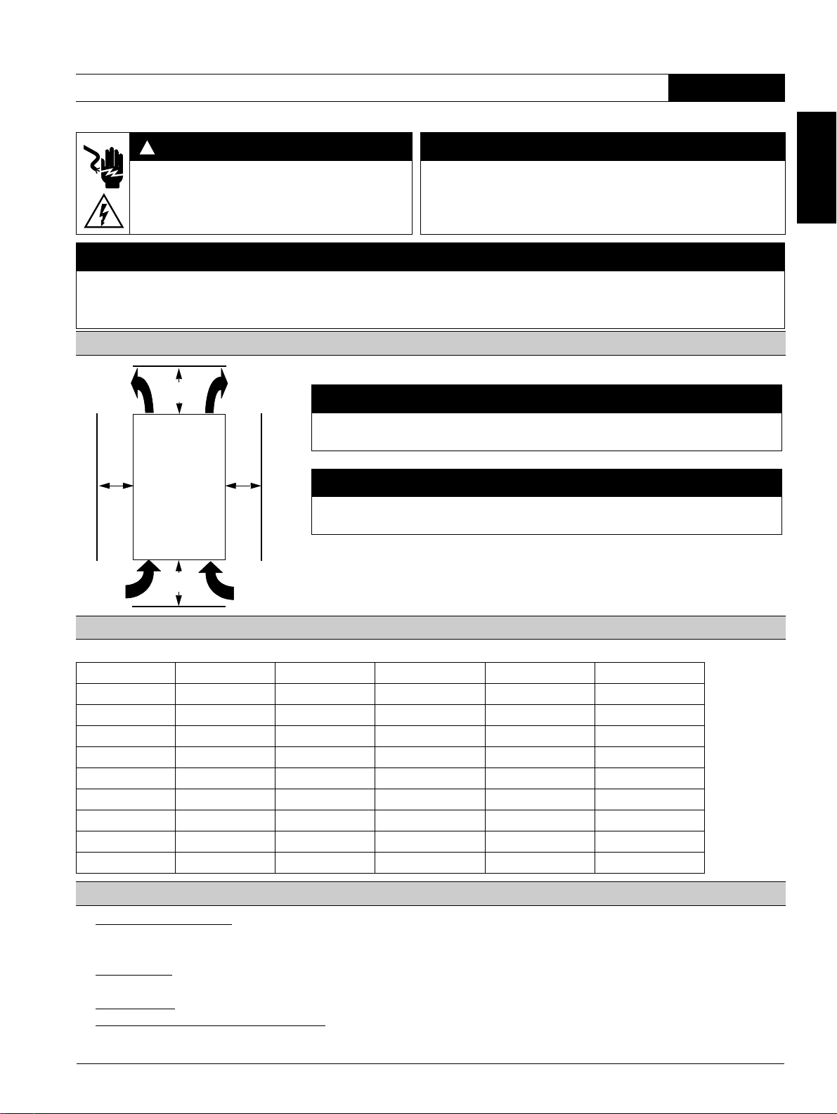
GEFAHR
Gefährliche Spannung. Lebensgefahr oder schwere Verletzungsgefahr.
Um elektrischen Stromschlag oder Verbrennungen zu vermeiden, dürfen die Klemmen des Motorsteuergeräts nicht berührt werden, wenn das
Gerät mit Spannung versorgt wird. An den Ausgangsklemmen steht auch im AUS-Zustand des Motorsteuergeräts Spannung an.
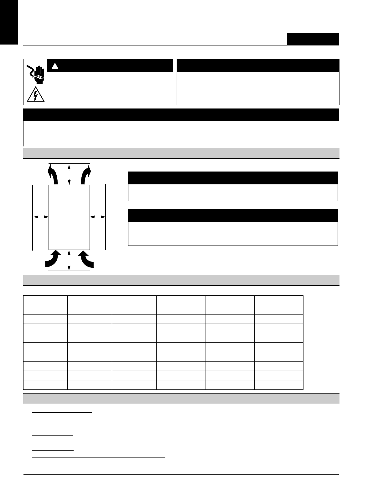
Einbauabstände in Einzelaufstellung (Dicht-an-dicht-Aufstellung siehe Sanftstarter-Handbuch)
≥ 60 mm
[≥ 2.36 in]
1
1
a
2
≥ 40 mm
[≥ 1.56 in]
5
3
a
6
4
a) 3RW40 2: 15 mm [0.59 in]
3RW40 3; 3RW40 4: 30 mm [1.18 in]
ACHTUNG
Beachten Sie beim Einbau des Geräts die angegebenen Abstände, damit genügend Luft für
Kühlung zirkulieren kann. Das Gerät wird von unten nach oben belüftet.
VORSICHT
Gefahr von Sachschäden.
Achten Sie darauf, dass keine Flüssigkeit, kein Staub oder leitender Gegenstand in den
Sanftstarter gelangt.
Motorstromeinstellwerte
Zulässige Motorstromeinstellwerte in Abhängigkeit von der CLASS-Einstellung bei 40° C Umgebungstemperatur
Ie [A] I
3RW40 24-... 12,5 5 12,5 11 10
3RW40 26-... 25,3 10 25,3 23 21
3RW40 27-... 32,2 17 32,2 30 27
3RW40 28-... 38 23 38 34 31
3RW40 36-... 45 22,5 45 42 38
3RW40 37-... 63 25,5 63 50 46
3RW40 38-... 72 34,5 72 56 50
3RW40 46-... 80 42,5 80 70 64
3RW40 47-... 106 46 106 84 77
[A] I
min
[A] CLASS 10 I
max
[A] CLASS 15 I
max
[A] CLASS 20
max
Programmieren des ON/RUN Ausgangs 13/14 (Werkseinstellung: ON) (Grafikteil, Bild 3)
1. Programmierung starten: (Beim Gerät 3RW40 2 die Abdeckung wie in Bild 2 gezeigt entfernen.) Die Taste "RESET MODE" (2)
länger als 2 s drücken, bis die LED "DEVICE" (5) grün flimmert. Die Taste "RESET MODE" (2) gedrückt halten und zusätzlich die
Taste "RESET/TEST" (1) länger als 1 s drücken, bis die LED "DEVICE" (5) am Gerät rot leuchtet.
2. Modus anzeigen:
mert grün: RUN-Modus.
3. Modus wechseln:
4. Programmierung beenden und Einstellungen speichern:
(5) grün leuchtet.
LED "STATE/BYPASSED/FAILURE" (6) blinkt grün: ON-Modus. LED "STATE/BYPASSED/FAILURE" (6) flim-
Taste "RESET MODE" (2) drücken.
Taste "RESET/TEST" (1) länger als 1 s drücken, bis die LED "DEVICE"
2 3ZX1012-0RW40-2DA1
Schnellinbetriebnahmeanleitung
Thermistoranschluss (nur 3RW40.-.TB0.)
– Anschluss Thermoclick gemäß Bild 6.3 (Drahtbrücke entfernen)
– Anschluss PTC Typ A gemäß Bild 6.4 (Drahtbrücke entfernen)
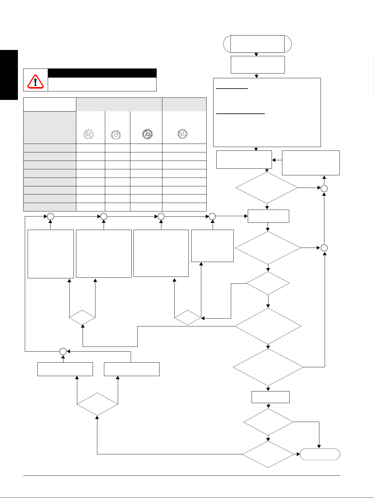
VORSICHT
Gefahr von Sachschäden!
Anschluss an nicht belegte Klemmen ist unzulässig.
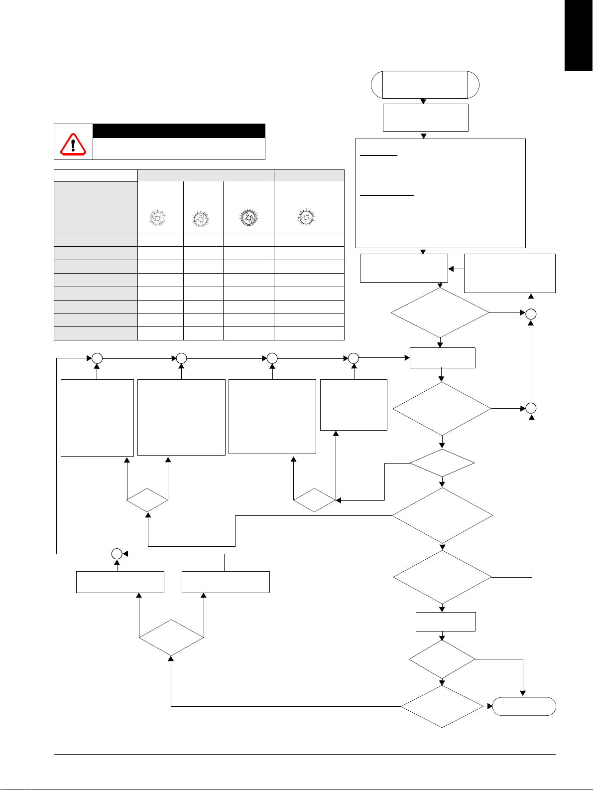
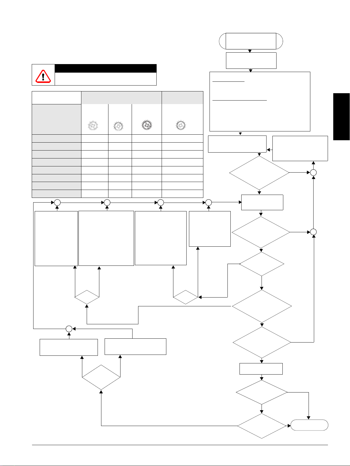
Einstellungsvorschlag
Applikation
Förderband
Rollenförderer
Kompressor
kleiner Ventilator
Pumpe
Hydraulikpumpe
Rührwerk
Fräsmaschine
1. Sanftstarter ausschalten (IN 1 -> 0).
2. Anlaufzeit erhöhen
(Poti nach
rechts drehen).
3. Strombegrenzungswert reduzieren
(Poti nach
links drehen).
Der Motor erreicht
seine Nenndrehzahl
- mit zu schnellem
Momentenanstieg
- schneller als
gewünscht,
mit zu hohem
Anlaufstrom
Auslaufzeit erhöhen
(Poti nach rechts drehen)
Der Motor bleibt
abrupt, nicht sanft
stehen.
spannung %
40
1. Sanftstarter ausschalten
(IN 1 -> 0).
2. Anlaufzeit reduzieren
(Poti nach links drehen)
oder
3. wenn Strombegrenzung
eingestellt ist, Begrenzungswert erhöhen (Poti
nach rechts drehen).
Motor:
Anlauf Parameter Auslauf Parameter
5
10
20s
Strombegren-
zungswert
xI
e
1.3
5xI
5xI
4xI
4xI
4xI
4xI
4xI
4xI
Start-
100%
Anlaufzeit s
0
70 10
60 10
50 10
40 10
40 10
40 10
40 20
40 20
1. Sanftstarter ausschalten
(IN 1 -> 0).
2. Startspannung erhöhen
(Poti nach rechts drehen)
oder
3. wenn Strombegrenzung
eingestellt ist, Begrenzungswert erhöhen (Poti
nach rechts drehen).
Der Motor
erreicht seine
Nenndrehzahl
- langsamer als
gewünscht,
- mit zu hohem
Anlaufstrom
- gar nicht
(bleibt hängen)
Auslaufzeit reduzieren
(Poti nach links drehen)
Der Motor läuft zu
lange nach.
Sanftauslauf
5
e
e
e
e
e
e
e
e
Der Motor
läuft nicht
sofort los
und brummt
Auslaufzeit s
5
10
0
20s
5
5
0
0
10
0
0
0
Motor:
2. Gerät parametrieren
Motorschutz
- am Ie-Einsteller Motorbemessungsstrom des
Antriebs einstellen
- am CLASS-Schalter erforderliche Abschaltklasse
einstellen.
Sanftstartfunktion
- Strombegrenzungswert (x Ie)
- Anlaufzeit (s)
- Startspannung (%)
- Auslaufzeit (s)
auf gewünschte Werte einstellen (siehe Tabelle
Einstellungsvorschlag).
3. Spannungen im Steuer-
und Hauptstromkreis überprüfen und zuschalten.
1. Sanftstarter ausschalten (IN 1 -> 0).
2. Startspannung
reduzieren (Poti
nach links drehen).
Der Motor
läuft mit
Momentenschlag an
Schnellinbetriebnahme
3RW40 SIRIUS
Sanftstarter
1. Verdrahtungskontrolle
- Steuerteil und
- Leistungsteil
LED "DEVICE"
grünes Dauerlicht,
die anderen LEDs
sind aus?
ja
4. Sanftstarter einschalten (IN 0 -> 1)
ja
"DEVICE" grün Dauerlicht,
LEDs:
"STATE/BYPASSED"
blinkt grün?
ja
nein
Motor läuft
sanft an?
ja
Motor
nein
erreicht zügig,
innerhalb der gewünschten
Zeit seine Nenn-
drehzahl?
ja
LEDs:
"DEVICE" grün
Dauerlicht, "STATE/
BYPASSED" grün
Dauerlicht?
ja
Sanftstarter aus-
schalten (IN 1 -> 0)
ja
Welche
Auslaufart ist
gewählt?
Sanftauslauf
nein
Motor
kommt wie gewünscht
zum Stillstand?
Über LED-Anzeige und
Zustandstabelle Fehlerursache ermitteln und beheben.
(siehe Seite 4)
nein
nein
nein
Freier Auslauf
ja
Inbetriebsetzung
beendet
Deutsch
3ZX1012-0RW40-2DA1 3
Deutsch
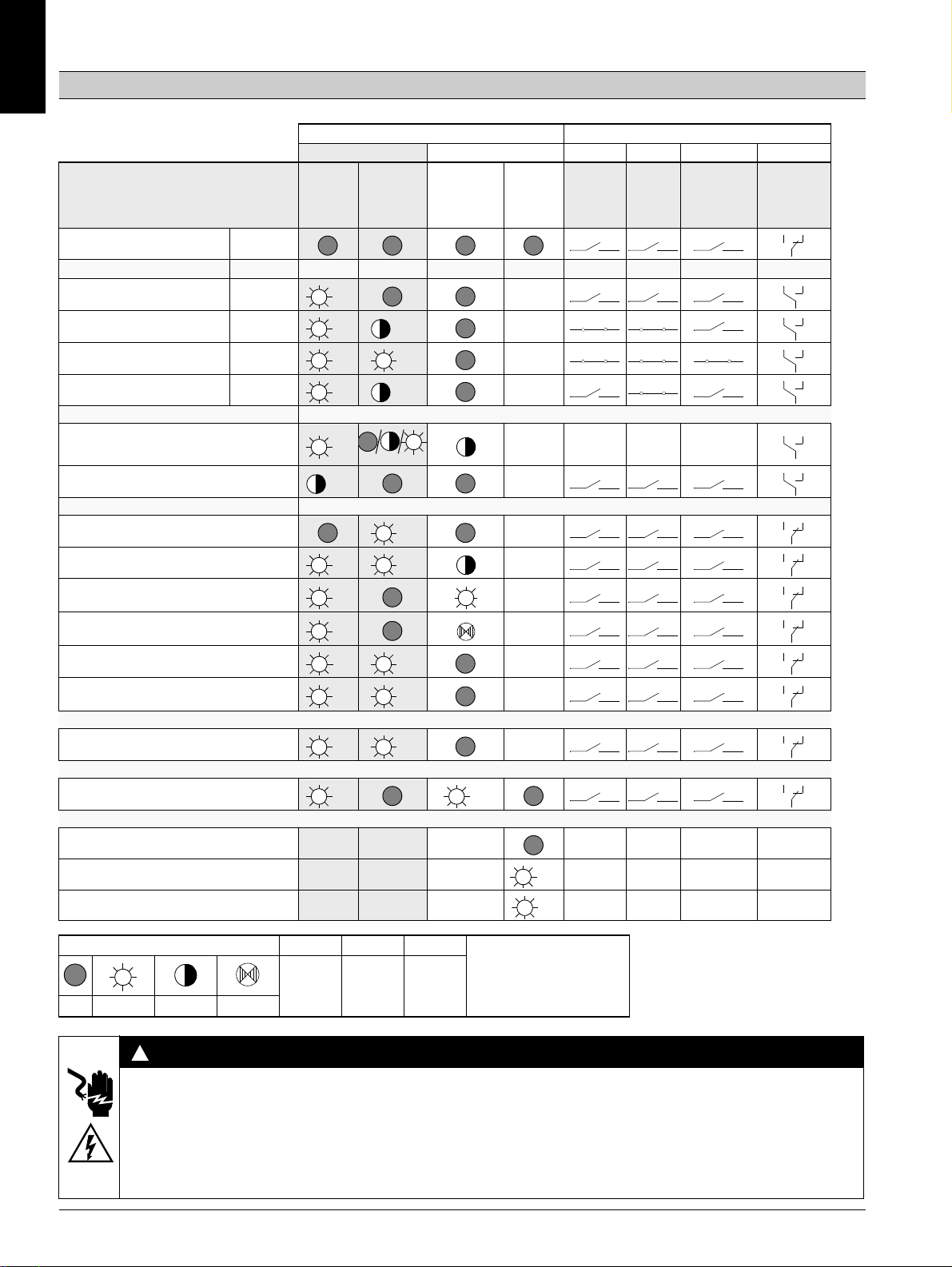
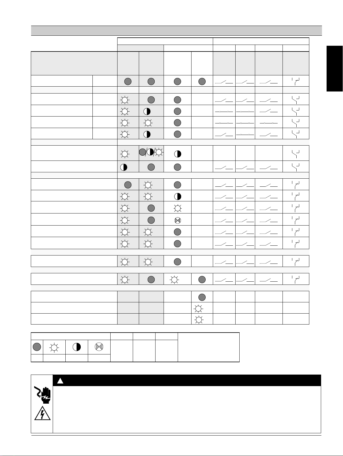
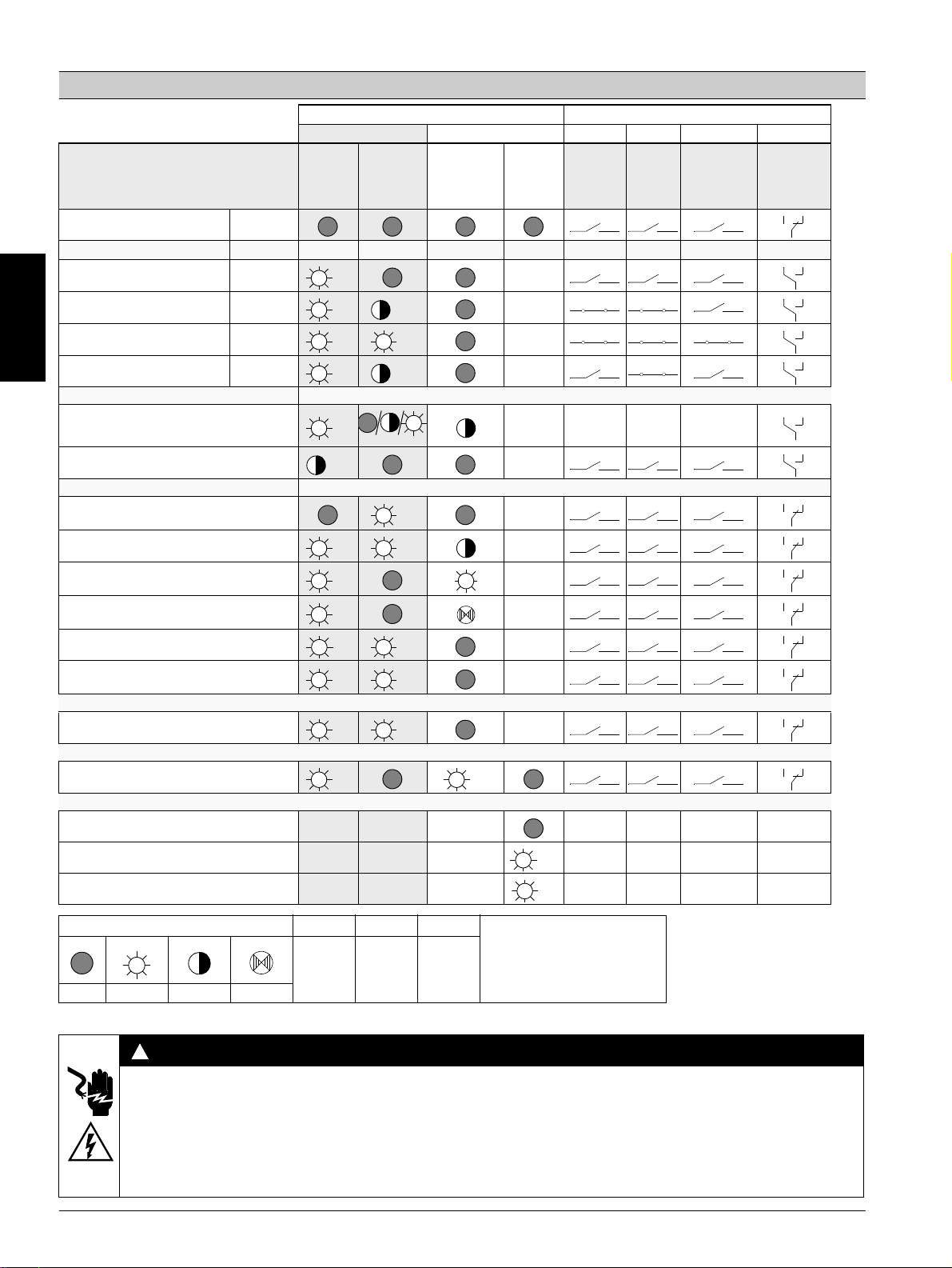
Anzeigenübersicht
3RW40
U
= 0
s
Betriebszustand
Aus
LED-Anzeigen 3RW40 Hilfskontakte
Sanftstarter Motorschutz
STATE /
DEVICE
(rd/gn/ylw)
BYPASSED
/ FAILURE
(gn/rd))
OVERLOAD
(rd)
RESET
MODE
(ylw/gn)
13 14
(ON)
13 14
(RUN)
24 23
(BYPASSED)
96 95 98
FAILURE /
OVERLOAD
IN
0
gn
Anlauf
Bypassed
Auslauf
Warnung
Ie/Class-Einstellung unzulässig
Start gesperrt, Gerät zu warm
Fehler
Versorgungsspannung Elektronik unzulässig
unzulässige Ie/Class-Einstellung und IN (0 -> 1)
Motorschutzabschaltung
Überlastrelais / Thermistor
Thermistormotorschutz
Drahtbruch / Kurzschluss
Thermische Überlastung Gerät
- fehlende Lastspannung
- Phasenausfall, fehlende Last
Gerätefehler
Testfunktion
1)
TEST t > 5 s drücken
RESET MODE (Drücken zum Wechseln)
Manual Reset
1
1
0
gn
gn gn
gn
gn
ylw
gn rd
gn
gn
ylw rd
gn rd
rd rd
gn rd
gn
gn
gn
gn
rd
Auto Reset
Remote Reset siehe Bild 6.2
ylw
gn
Anzeige der LEDs
gn
=
ylw
=
rd
1)
Test Motorschutzabschaltung
=
aus ein blinkend flimmernd grün gelb rot
WARNUNG
!
Automatischer Wiederanlauf.
Kann zu Tod, schwerer Körperverletzung oder Sachbeschädigung führen.
Der automatische Rücksetzmodus (RESET MODE) darf nicht in Anwendungen verwendet werden, in denen der unerwartete Neustart
des Motors nach Ablauf der Wiederbereitschaftszeit zu Personen- oder Sachschäden führen kann.
Der Startbefehl (z. B. durch die SPS) muss vor einem Resetbefehl zurückgesetzt werden, da bei anstehendem Startbefehl nach dem
Resetbefehl automatisch ein erneuter, selbsttätiger Wiederanlauf erfolgt. Dies gilt insbesondere bei Motorschutzauslösung. Aus
Sicherheitsgründen wird empfohlen, den Sammelfehlerausgang (Klemmen 95 und 96) in die Steuerung einzubinden.
4 3ZX1012-0RW40-2DA1
Soft starter 3RW40 2, 3RW40 3, 3RW40 4 English
Read and understand these instructions before installing, operating, or maintaining the equipment.
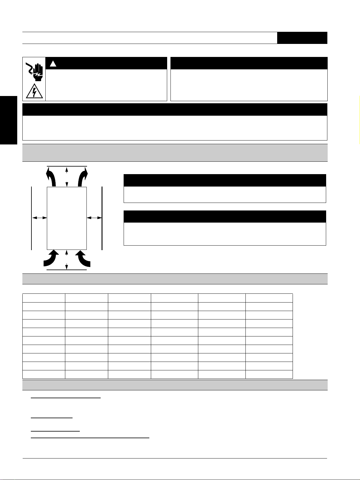
DANGER
!
CAUTION
Hazardous voltage.
Will cause death or serious injury.
Disconnect power before working on equipment.
Reliable functioning of the equipment is only ensured with certified
components.
DANGER
Dangerous voltage. Danger to life or danger of serious injury.
The terminals of the motor control device must not be touched when it is connected to a voltage in order to prevent electrical shocks or burning.
The output terminals of the motor control device are connected to a voltage even when it is in the OFF state.
Stand-alone installation spacings (see soft starter manual for side-by-side installation)
≥ 60 mm
[≥ 2.36 in]
1
1
a
2
≥ 40 mm
[≥ 1.56 in]
5
3
a
6
4
a) 3RW40 2: 15 mm [0.59 in]
3RW40 3; 3RW40 4: 30 mm [1.18 in]
NOTICE
Please adhere to the specified spacings when installing the device so that sufficient air can
circulate for ventilation. The unit is ventilated from bottom to top.
CAUTION
Risk of damage to property.
Ensure that no liquids, dust or conductive parts enter the soft starter.
English
Setpoint values for motor current
Permitted setpoint values for the motor current, dependent on the CLASS setting at 40 °C ambient temperature
Ie [A] I
3RW40 24-... 12.5 5 12.5 11 10
3RW40 26-... 25.3 10 25.3 23 21
3RW40 27-... 32.2 17 32.2 30 27
3RW40 28-... 38 23 38 34 31
3RW40 36-... 45 22.5 45 42 38
3RW40 37-... 63 25.5 63 50 46
3RW40 38-... 72 34.5 72 56 50
3RW40 46-... 80 42.5 80 70 64
3RW40 47-... 106 46 106 84 77
[A] I
min
[A] CLASS 10 I
max
[A] CLASS 15 I
max
[A] CLASS 20
max
Programming the ON/RUN output 13/14 (factory setting: ON) (Fig. 3 in graphics section)
1. Start programming mode:
button (2) for longer than 2 seconds until the LED "DEVICE" (5) flickers green. While pushing the "RESET MODE" button (2),
press the "RESET/TEST" button (1) for longer than 1 second until the LED "DEVICE" (5) on the device lights up red.
2. Display mode:
LED "STATE/BYPASSED/FAILURE" (6) flashes green: ON mode. LED "STATE/BYPASSED/FAILURE" (6) flickers
green: RUN mode.
3. Change mode:
Press the "RESET MODE" (2) button.
4. Exit programming mode and save settings: Press and hold the "RESET/TEST" button (1) for longer than 1 second until the LED
"DEVICE" (5) lights up green.
(For the 3RW40 2 device, remove the cover as shown in Figure 2.) Press and hold the "RESET MODE"
3ZX1012-0RW40-2DA1 5
Quick commissioning instructions
Thermistor connection (3RW40.-.TB0. only)
– Thermoclick connection according to Fig. 6.3 (remove jumper)
– PTC connection type A according to Fig. 6.4
English
CAUTION
Risk of damage to property!
Connection to an unassigned terminal is not permitted.
Suggested setting
Application
Conveyor belt
Roller conveyor
Compressor
Small fan
Pumps
Hydraulic pump
Stirrers
Milling machines
1. Switch soft starter
off (IN 1 -> 0).
2. Increase startup
time (turn potentiometer clockwise).
3. Reduce current limit
value (turn
potentiometer anticlockwise).
The motor reaches
its nominal rotational
speed
- with a torque
increase that is too
high
- faster than desired,
with a startup
current that is too
high
voltage %
40
1. Switch off soft starter
(IN 1 -> 0).
2. Reduce startup time (turn
potentiometer anticlockwise).
or
3. Increase limit value if the
current limit is set (turn
potentiometer clockwise).
Motor:
Startup parameters
Start
100%
70 10
60 10
50 10
40 10
40 10
40 10
40 20
40 20
The motor reaches
its nominal
rotational speed
- slower than
desired,
- with a startup
current that is too
high
- not at all
(motor stuck)
Startup
time s
5
0
Current limit
value
xI
10
20s
1.3
e
5xI
5xI
4xI
4xI
4xI
4xI
4xI
4xI
5
e
e
e
e
e
e
e
e
1. Switch off soft starter
(IN 1 -> 0).
2. Increase start voltage
(turn potentiometer
clockwise)
or
3. Increase limit value if the
current limit is set (turn
potentiometer clockwise).
The motor
hums and
does not
start
immediately
Stopping
parameters
Stopping time s
5
10
0
20s
5
5
0
0
10
0
0
0
1. Switch soft starter
off (IN 1 -> 0).
2. Reduce start
voltage (turn
potentiometer anticlockwise).
Motor:
Quick commissioning of
the 3RW40 SIRIUS
soft starter
1. Wiring control
- Control part and
- Performance part
2. Configure device
Motor protection
- Set the rated motor current of the device using the
I
controller
e
- Set required switch-off class with the CLASS
switch.
Set the soft start function
- Current limit value (x Ie)
- Startup time (s)
- Start voltage (%)
- Stopping time (s)
to the desired value (see table for suggested
settings).
3. Check and connect the
voltages in the control and
main circuits.
"DEVICE" LED
cont. green light,
are the other LEDs
off?
Determine and rectify the
cause of the fault using the
LED display and the status
table (see Page 7).
Yes
4. Switch soft starter
on (IN 0 -> 1)
Yes
LEDs:
"DEVICE" cont. green
light, "STATE/BYPASSED"
flashing green?
The motor
starts with a
sudden
increase in
torque
No
Yes
Does
the motor
start softly?
Yes
Does
No
the motor reach
its nominal rotational speed
quickly and within the
desired time?
Yes
No
No
Increase stopping time (turn
potentiometer clockwise)
The motor stops
abruptly and not
softly.
Soft stopping
Reduce stopping time (turn
potentiometer anticlockwise)
The motor keeps
going for too long.
"DEVICE" cont. green light,
"STATE/BYPASSED" green
LEDs:
cont. light?
Yes
Switch soft starter
off (IN 1 -> 0)
Yes
Which type of
stopping has been
selected?
No
Coasting down
Soft stopping
No
Motor
reaches stationary
state as desired?
Yes
End of
commissioning
6 3ZX1012-0RW40-2DA1
Display overview
3RW40
U
= 0
s
Operating state
OFF
LED displays on 3RW40 Auxiliary contacts
Soft starter Motor protection
DEVICE
(rd/gn/ylw)
STATE /
BYPASSED
/ FAILURE
(gn/rd)
OVERLOAD
(rd)
RESET
MODE
(ylw/gn)
13 14
(ON)
13 14
(RUN)
24 23
(BYPASSED)
96 95 98
FAILURE /
OVERLOAD
English
IN
0
gn
Start-up
Bypassed
Run-out
Warning
Ie / class setting invalid
Start-up locked, device too warm
Error
Supply voltage electronics invalid
Invalid Ie / class setting and IN (0 -> 1)
Motor protection switch-off
Overload relay / thermistor
Thermistor motor protection
Wire break / short circuit
Thermal overload device
- Missing load voltage
- Phase failure, no load
Device fault
Test function
1)
Press TEST for t > 5 s
RESET MODE (press to change)
Manual Reset
1
1
0
gn
gn gn
gn
gn
ylw
gn rd
gn
gn
ylw rd
gn rd
rd rd
gn rd
gn
gn
gn
gn
rd
Auto Reset
Remote Reset see Fig. 6.2
ylw
gn
LED display
gn
=
ylw
rd
1)
=
Motor protection shutdown test
=
OFF ON flashing flickering green yellow red
WARNING
!
Automatic restart.
May result in death, serious injury or damage to property.
The automatic reset mode (RESET MODE) must not be used in applications where an unexpected restart of the motor after the
recovery time has elapsed may lead to personal injury or damage to property.
The start command (e.g. by the PLC) must be reset before a reset command, since an automatic restart is executed when a start
command is pending after the reset command. This especially applies to motor protection tripping. For safety reasons we recommend
you integrate the group fault output (terminals 95 and 96) into the control.
3ZX1012-0RW40-2DA1 7
Démarreur progressif 3RW40 2, 3RW40 3, 3RW40 4 Français
Ne pas installer, utiliser ou intervenir sur cet équipement avant d'avoir lu et assimilé ces instructions..
DANGER
!
PRUDENCE
Tension dangereuse.
Danger de mort ou risque de blessures graves.
Mettre hors tension avant d’intervenir sur l’appareil.
Le fonctionnement sûr de l'appareil n'est garanti qu'avec des
composants certifiés.
Français
DANGER
Tension dangereuse. Danger de mort ou danger de lésions graves.
Il est interdit de toucher les bornes du bloc de commande du moteur lorsque l’appareil est sous tension pour éviter les chocs électriques ou les
brûlures. Une tension est présente aux bornes de sortie même à l’ARRET du bloc de commande du moteur.
Distances de montage pour installation séparée (installation juxtaposée, voir le manuel Démarreurs
progressifs)
≥ 60 mm
[≥ 2.36 in]
1
1
a
2
5
3
a
6
4
IMPORTANT
Veuillez respecter au montage de l’appareil les distances indiquées pour assurer une circulation
suffisante de l’air de refroidissement. L’appareil est ventilé du bas vers le haut.
PRUDENCE
Risque de dommages matériels.
Veuillez à ce que ni liquide, ni poussière ou objet conducteur ne puisse pénétrer dans le
démarreur progressif.
≥ 40 mm
[≥ 1.56 in]
a) 3RW40 2 : 15 mm [0.59 in]
3RW40 3 ; 3RW40 4 : 30 mm [1.18 in]
Valeurs de réglage du courant du moteur
Valeurs de réglage du courant du moteur admissible en fonction du CLASS à une température ambiante de 40° C
Ie [A] I
3RW40 24-... 12,5 5 12,5 11 10
3RW40 26-... 25,3 10 25,3 23 21
3RW40 27-... 32,2 17 32,2 30 27
3RW40 28-... 38 23 38 34 31
3RW40 36-... 45 22,5 45 42 38
3RW40 37-... 63 25,5 63 50 46
3RW40 38-... 72 34,5 72 56 50
3RW40 46-... 80 42,5 80 70 64
3RW40 47-... 106 46 106 84 77
[A] I
min
[A] CLASS 10 I
max
[A] CLASS 15 I
max
[A] CLASS 20
max
Programmation de la sortie ON/RUN 13/14 (réglage standard : ON) (partie graphique, figure 3)
1. Lancement de la programmation : (retirez tout d’abord le couvercle de l’appareil 3RW40 2 comme le montre la figure 2.) Appuyez sur la touche
"RESET MODE" (2) pendant plus de 2 secondes jusqu’à ce que la LED verte "DEVICE" (5) scintille. Maintenez la touche "RESET MODE" (2)
appuyée et pressez la touche "RESET/TEST" (1) pendant plus de 1 s, jusqu’à ce que la LED rouge "DEVICE" (5) scintille sur l’appareil.
2. Affichage du mode :
scintille : mode RUN.
3. Changement de mode :
4. Fin de la programmation et enregistrement des réglages :
LED verte "DEVICE" (5) s’allume.
la LED verte "STATE/BYPASSED/FAILURE" (6) clignote : mode ON. La LED verte "STATE/BYPASSED/FAILURE" (6)
appuyez sur la touche "RESET MODE" (2).
appuyez sur la touche "RESET/TEST" (1) pendant plus d’1 seconde jusqu’à ce que la
8 3ZX1012-0RW40-2DA1
Instructions de mise en service rapide
Raccordement de thermistance (uniquement 3RW40.-.TB0.)
– Raccordement du thermoclick selon la figure 6.3 (retirer les ponts à fil)
– Raccordement PTC type A selon la figure 6.4
PRUDENCE
Risque de dommages matériels !
Un raccordement aux bornes libres est inadmissible.
Proposition de réglage
Application
Convoyeur
Convoyeur à rouleaux
Compresseur
Petit ventilateur
Pompe
Pompe hydraulique
Malaxeur
Fraiseuse
1. Arrêt du démarreur
progressif (IN 1 -> 0).
2. Allonger le temps de
démarrage
(potentiomètre
vers la droite).
3. Réduire la valeur de
limitation de courant
(potentiomètre vers la
gauche).
Le moteur atteint sa
vitesse nominale
- avec une montée
de couple trop
rapide
- plus rapidement
que souhaité, avec
un courant de
démarrage trop fort
1. Arrêt du démarreur
progressif (IN 1 -> 0).
2. Réduire le temps de
démarrage (potentiomètre
vers la gauche)
ou
3. Augmenter la valeur de
limitation si réglage de
limitation de courant
(potentiomètre vers la droite).
Moteur
Paramètres de démarrage
Tension
démarrage %
40
100%
0
70 10
60 10
50 10
40 10
40 10
40 10
40 20
40 20
Le moteur atteint
sa vitesse
nominale
- plus lentement
que souhaité,
:
- avec courant de
démarrage trop fort
- pas du tout
(s'arrête)
Te mp s
dém. s
5
Val. limitation
courant
xI
e
10
1.3
20s
5
5xI
e
5xI
e
4xI
e
4xI
e
4xI
e
4xI
e
4xI
e
4xI
e
1. Arrêt du démarreur
progressif (IN 1 -> 0).
2. Augmenter la tension de
démarrage (potentiomètre
vers la droite)
ou
3.Augmenter la valeur de
limitation si réglage de
limitation de courant
(potentiomètre vers la
droite).
Le moteur ne
démarre pas
immédiatement
et ronfle
Temps ralent. s
Paramètres de
ralentissement
5
10
0
20s
5
5
0
0
10
0
0
0
1. Arrêt du démarreur
progressif (IN 1 -> 0).
2. Réduire la tension
de démarrage
(potentiomètre vers
la gauche)
Moteur :
Mise en service rapide
3RW40 SIRIUS
démarreur progressif
1. Contrôle du câblage
- bloc de commande et
- bloc de puissance
2. Paramétrage de l’appareil
Protection moteur
- sur régleur Ie régler le courant assigné du moteur
- régler la classe de coupure nécessaire sur le
commutateur CLASS.
Fonction démarreur progressif
- valeur limitation de courant (x Ie)
- temps démarrage (s)
- tension de démarrage (%)
- temps de ralentissement (s)
à régler sur les valeurs souhaitées (voir le tableau
Proposition de réglage).
3. Contrôler et mettre en circuit
les tensions dans le circuit
principal et de commande.
LED "DEVICE"
feu fixe vert,
les autres LED
sont éteintes ?
oui
4. Mettre en marche
le démarreur
progressif (IN 0 -> 1)
oui
LED :
"DEVICE" feu fixe
vert, "STATE/BYPASSED"
vert clignotant ?
oui
Le moteur
démarre
avec choc de
couple
non
Moteur en
marche progressive-
ment ?
oui
Le moteur
non
atteint rapidement,
sa vitesse nominale dans le
temps souhaité ?
Déterminer et supprimer
l’origine du défaut via
l’affichage LED et la table des
états.
(voir Page 10)
non
non
Français
oui
LED :
Allonger le temps de
ralentissement
(potentiomètre vers la droite)
Le moteur s'arrête de
manière abrupte et
non progressive.
Ralentissement
Réduire le temps de
ralentissement
(potentiomètre vers la gauche)
Le moteur poursuit
sa marche encore
trop longtemps.
progressif
"DEVICE" vert
feu fixe, "STATE/
BYPASSED" vert
feu fixe ?
oui
Arrêt du démarreur
progressif (IN 1 -> 0)
oui
Quel mode
de ralentissement
sélectionné ?
non
Ralentissement naturel
Ralentissement progressif
non
Le moteur
s’arrête comme
prévu ?
Mise en service
oui
achevée
3ZX1012-0RW40-2DA1 9
Vue d’ensemble des affichages
3RW40
U
= 0
s
Etat de fonctionnement
Français
Arrêté
LED de signalisation 3RW40 Contacts auxiliaires
Démarreur progressif Protection moteur
STATE /
DEVICE
(rd/gn/ylw)
BYPASSED
/ FAILURE
(gn/rd))
OVERLOAD
(rd)
IN
0
gn
RESET
MODE
(ylw/gn)
13 14
(ON)
13 14
(RUN)
24 23
(BYPASSED)
96 95 98
FAILURE /
OVERLOAD
Démarrage
Bypassed
Ralentissement
Alarme
Réglage Ie/Class incorrect
Démarrage bloqué, appareil trop chaud
Défauts
Tension d’alimentation de l’électronique
incorrecte
Réglage Ie/Class incorrect et IN (0 -> 1)
Coupure du moteur par protection
Relais de surcharge / thermistance
Protection des moteurs par thermistance
Rupture de câble / court-circuit
Surcharge thermique appareil
- manque de tension de charge
- coupure de phase, charge non raccordée
Défaut sur l’appareil
Fonction de test
1)
Appuyer sur TEST t > 5 s
RESET MODE (appuyer pour changer)
Reset manuel
1
1
0
gn
gn gn
gn
gn
ylw
gn rd
gn
gn
ylw rd
gn rd
rd rd
gn rd
gn
gn
gn
gn
rd
Reset automatique
Remote Reset voir la figure 6.2
ylw
gn
Affichage des LED
gn
=
éteinte allumée clignotante scintillante verte jaune rouge
ATTENTION
!
ylw
=
rd
=
1)
Test Coupure protection moteur
Redémarrage automatique.
Peut causer la mort, des lésions graves ou des dommages matériels.
Le réarmement automatique (RESET MODE) ne peut être utilisé dans des applications où le redémarrage inattendu du moteur après
le temps du récupération peut provoquer des lésions ou des dommages matériels importants. L’ordre de marche (de l’API par ex.) doit
être annulé avant de donner l’ordre de réarmement ; en effet, la présence de l’ordre de marche à la suite du réarmement donne lieu à
un redémarrage automatique. Ceci vaut tout particulièrement pour le déclenchement de protection du moteur. Pour des raisons de
sécurité, il est recommandé d’intégrer la sortie de signalisation de défauts groupés (bornes 95 et 96) à la commande.
10 3ZX1012-0RW40-2DA1
 Loading...