

Siemens SIRIUS 3RT User Manual
Manual
Industrial Controls
Switching Devices
SIRIUS - SIRIUS 3RT Contactors /
Contactor assemblies
Edition
09/2017
siemens.com


___________________
___________________
___________________
___________________
___________________
___________________
___________________
___________________
___________________
___________________
___________________
___________________
___________________
___________________
Industrial Controls
Switching devices
SIRIUS - SIRIUS 3RT
Contactors/Contactor assemblies
Manual
09/2017
A5E03656507120A/RS
Introduction
1
Standards
2
Safety instructions
3
Product description
4
Product combinations
5
Configuration
6
Mounting
7
Connection
8
Accessories
9
Technical data
10
Circuit diagrams
11
Types of coordination
A
References
B
Dimension drawings
(dimensions in mm)
C
-AE/006
Siemens AG
Division Digital Factory
Postfach 48 48
90026 NÜRNBERG
GERMANY
3ZX1012-0RT20-5AC1
Ⓟ
Copyright © Siemens AG 2011.
All rights reserved
Legal information
Warning notice system
DANGER
indicates that death or severe personal injury will result if proper precautions are not taken.
WARNING
indicates that death or severe personal injury may result if proper precautions are not taken.
CAUTION
indicates that minor personal injury can result if proper precautions are not taken.
NOTICE
indicates that property damage can result if proper precautions are not taken.
Qualified Personnel
personnel qualified
Proper use of Siemens products
WARNING
Siemens products may only be used for the applications described in the catalog and in the relevant technical
maintenance are required to ensure that the products operate safely and without any problems. The permissible
ambient conditions must be complied with. The information in the relevant documentation must be observed.
Trademarks
Disclaimer of Liability
This manual contains notices you have to observe in order to ensure your personal safety, as well as to prevent
damage to property. The notices referring to your personal safety are highlighted in the manual by a safety alert
symbol, notices referring only to property damage have no safety alert symbol. These notices shown below are
graded according to the degree of danger.
If more than one degree of danger is present, the warning notice representing the highest degree of danger will
be used. A notice warning of injury to persons with a safety alert symbol may also include a warning relating to
property damage.
The product/system described in this documentation may be operated only by
task in accordance with the relevant documentation, in particular its warning notices and safety instructions.
Qualified personnel are those who, based on their training and experience, are capable of identifying risks and
avoiding potential hazards when working with these products/systems.
Note the following:
documentation. If products and components from other manufacturers are used, these must be recommended
or approved by Siemens. Proper transport, storage, installation, assembly, commissioning, operation and
All names identified by ® are registered trademarks of Siemens AG. The remaining trademarks in this publication
may be trademarks whose use by third parties for their own purposes could violate the rights of the owner.
We have reviewed the contents of this publication to ensure consistency with the hardware and software
described. Since variance cannot be precluded entirely, we cannot guarantee full consistency. However, the
information in this publication is reviewed regularly and any necessary corrections are included in subsequent
editions.
for the specific
09/2017 Subject to change

Table of contents
1 Introduction ........................................................................................................................................... 13
2 Standards ............................................................................................................................................. 21
3 Safety instructions ................................................................................................................................. 29
4 Product description ............................................................................................................................... 31
1.1 Responsibility of the user for system configuration and functionality ..................................... 13
1.2 Purpose of the manual ............................................................................................................ 14
1.3 Advantages through energy efficiency .................................................................................... 15
1.4 Required basic knowledge ...................................................................................................... 15
1.5 Scope of the manual ............................................................................................................... 15
1.6 Siemens Industry Online Support ........................................................................................... 16
1.7 Further documentation ............................................................................................................ 17
1.8 DataMatrix code ...................................................................................................................... 18
1.9 Siemens Industry Online Support app .................................................................................... 18
1.10 Recycling and disposal ........................................................................................................... 19
1.11 Technical Assistance .............................................................................................................. 19
2.1 Standards and product approvals ........................................................................................... 21
2.2 Protective separation .............................................................................................................. 23
2.3 Positively driven contact elements/Mirror contacts ................................................................. 24
2.4 Used for stop category 0 / 1 .................................................................................................... 25
2.5 IE3 / IE4 ready ........................................................................................................................ 26
2.6 Applications ............................................................................................................................. 27
3.1 General safety notes ............................................................................................................... 29
3.2 Intended use ........................................................................................................................... 30
3.3 Current information about operational safety ......................................................................... 30
4.1 Overview of the contactor range ............................................................................................. 31
4.2 Device versions ....................................................................................................................... 35
4.2.1 3RT2 power contactors ........................................................................................................... 36
4.2.2 3RT10 / 3RT14 power contactors and 3RT12 vacuum contactors ........................................ 41
4.2.3 3RH2 contactor relays ............................................................................................................ 47
4.2.4 3RT26 capacitor contactors .................................................................................................... 50
4.2.5 3RA23 reversing contactor assemblies .................................................................................. 56
4.2.6 3RA24 contactor assemblies for star-delta (wye-delta) start .................................................. 59
4.2.7 Drive options ........................................................................................................................... 63
SIRIUS - SIRIUS 3RT Contactors/Contactor assemblies
Manual, 09/2017, A5E03656507120A/RS-AE/006
5

Table of contents
5 Product combinations............................................................................................................................ 65
6 Configuration ........................................................................................................................................ 67
4.3 Reference ............................................................................................................................... 63
6.1 Overview of applications for contactors and contactor assemblies ....................................... 67
6.2 SIRIUS system configurator ................................................................................................... 68
6.3 Operating mechanism system / coil selection 3RT contactors and 3RH2 contactor
relays ...................................................................................................................................... 69
6.3.1 Operating mechanism system / coil selection 3RT2 contactors and 3RH2 contactor
relays ...................................................................................................................................... 69
6.3.2 Operating mechanism system / coil selection 3RT1 contactors ............................................ 70
6.3.2.1 Conventional operating mechanism....................................................................................... 72
6.3.2.2 Solid-state operating mechanism for standard contactors .................................................... 73
6.3.2.3 Solid-state operating mechanism for standard contactors with remaining lifetime signal
RLT ........................................................................................................................................ 77
6.3.2.4 Solid-state operating mechanism for contactors with extended operating range and rail
applications ............................................................................................................................ 83
6.3.2.5 Solid-state operating mechanism for contactors with fail-safe control input .......................... 85
6.3.2.6 Typical circuit diagrams (standard contactors) ...................................................................... 87
6.4 Application environment ......................................................................................................... 89
6.4.1 3RH2 contactor relays ........................................................................................................... 89
6.4.2 3RT power contactors ............................................................................................................ 90
6.4.3 Contactors for railway applications ........................................................................................ 93
6.4.4 Installation altitude ................................................................................................................. 94
6.5 Switching motorized loads ..................................................................................................... 95
6.6 Switching resistive loads ...................................................................................................... 100
6.7 Changing the polarity of hoisting gear motors ..................................................................... 103
6.8 Switching in the auxiliary circuit ........................................................................................... 105
6.9 Switching of capacitive loads ............................................................................................... 106
6.10 Contactors with extended operating range .......................................................................... 114
6.10.1 Contactors for rail applications according to IEC 60077-2 .................................................. 114
6.10.2 Coupling relays .................................................................................................................... 116
6.10.2.1 Technical background information ....................................................................................... 117
6.11 Contactors in safety applications ......................................................................................... 118
6.11.1 Safety notes ......................................................................................................................... 118
6.11.1.1 General safety notes ............................................................................................................ 118
6.11.1.2 Intended use ........................................................................................................................ 119
6.11.1.3 Current information about operational safety ....................................................................... 121
6.11.1.4 Security information ............................................................................................................. 121
6.11.2 Examples/applications ......................................................................................................... 122
6.11.2.1 User responsibility for system design and function .............................................................. 122
6.11.2.2 Safety information ................................................................................................................ 123
6.11.2.3 Layout of application examples ............................................................................................ 124
6.11.2.4 P-switching fail-safe outputs ................................................................................................ 125
6.11.2.5
PM-switching fail-safe outputs ............................................................................................. 132
6.12 Operation of a motor in two directions of rotation (reversing contactor assembly) ............. 140
SIRIUS - SIRIUS 3RT Contactors/Contactor assemblies
6 Manual, 09/2017, A5E03656507120A/RS-AE/006

Table of contents
7 Mounting ............................................................................................................................................. 179
8 Connection ......................................................................................................................................... 227
9 Accessories ........................................................................................................................................ 243
6.12.1 Reference ............................................................................................................................. 146
6.13 Starting three-phase motors with reduced starting current peaks (contactor assembly
for star-delta (wye-delta) start) .............................................................................................. 147
6.13.1 Reference ............................................................................................................................. 152
6.13.2 Technical background information ........................................................................................ 153
6.14 Using long control cables ...................................................................................................... 158
6.15 Configuration information for use downstream of frequency converters .............................. 164
6.16 Contact service life of auxiliary and main contacts ............................................................... 166
6.16.1 3RT2 power contactors (sizes S00 to S3) ............................................................................ 166
6.16.1.1 Contact service life of auxiliary and main contacts (sizes S00 and S0) ............................... 166
6.16.1.2 Contact service life of auxiliary and main contacts (size S2)................................................ 169
6.16.1.3 Contact service life of auxiliary and main contacts (size S3)................................................ 171
6.16.2 3RT26 capacitor contactors (sizes S00 to S3) ..................................................................... 173
6.16.2.1 Contact service life of auxiliary and main contacts ............................................................... 173
6.16.3 3RT10 power contactors and 3RT12 vacuum contactors (sizes S6 to S12) ........................ 175
6.16.3.1 Mechanical endurance .......................................................................................................... 175
6.16.3.2 Electrical endurance ............................................................................................................. 175
7.1 Warning notice ...................................................................................................................... 179
7.2 Mounting ............................................................................................................................... 179
7.2.1 Mounting options ................................................................................................................... 179
7.2.2 Mounting position .................................................................................................................. 180
7.2.3 Mounting on mounting plate / wall mounting ........................................................................ 181
7.2.4 Snapping onto DIN rail (snap-on mounting) ......................................................................... 185
7.3 Replacing solenoid coils ....................................................................................................... 188
7.3.1 Replacing solenoid coils for size S0 ..................................................................................... 188
7.3.2 Replacing solenoid coils for size S2 ..................................................................................... 191
7.3.3 Replacing solenoid coils for size S3 ..................................................................................... 196
7.3.4 Replacing solenoid coils for sizes S6-S12 ............................................................................ 202
7.4 Contact piece replacement (sizes S2 to S12) ...................................................................... 205
7.4.1 Contact piece replacement (size S2) .................................................................................... 205
7.4.2 Contact piece replacement (size S3) .................................................................................... 211
7.4.3 Contact piece replacement (size S6) .................................................................................... 217
7.4.4 Contact piece replacement (size S10 and S12) ................................................................... 219
7.5 Replacing the vacuum interrupters (sizes S10 and S12) ..................................................... 222
8.1 Warning notice ...................................................................................................................... 227
8.2 Conductor cross-sections ..................................................................................................... 230
8.2.1 Conductor cross-sections for screw-type connection systems ............................................. 230
8.2.2 Conductor cross-sections for spring-loaded connection systems ........................................ 238
8.2.3 Conductor cross-sections for ring cable lug connection system .......................................... 240
9.1 Overview of accessories for 3RT2 contactors ...................................................................... 243
9.1.1 Overview of accessories for 3RT2 contactors ...................................................................... 243
SIRIUS - SIRIUS 3RT Contactors/Contactor assemblies
Manual, 09/2017, A5E03656507120A/RS-AE/006
7

Table of contents
9.2 Overview of accessories for 3RT1 contactors ..................................................................... 253
9.2.1 Overview of accessories for 3RT1 contactors ..................................................................... 253
9.3 Auxiliary switch blocks ......................................................................................................... 255
9.3.1 Auxiliary switch block for 3RT2 power contactors and 3RH2 contactor relays ................... 255
9.3.1.1 Description ........................................................................................................................... 255
9.3.1.2 Configuration ........................................................................................................................ 258
9.3.1.3 Selection guide for mountable auxiliary switch blocks for power contactors and
contactor relays .................................................................................................................... 264
9.3.1.4 Mounting/Disassembly ......................................................................................................... 284
9.3.2 Auxiliary switch blocks for 3RT1 power contactors .............................................................. 287
9.3.2.1 Description ........................................................................................................................... 287
9.3.2.2 Configuration ........................................................................................................................ 290
9.3.2.3 Terminal designations and identification numbers for auxiliary contacts............................. 292
9.3.2.4 Mounting/Disassembly ......................................................................................................... 293
9.4 Surge suppressor ................................................................................................................. 296
9.4.1 Description ........................................................................................................................... 296
9.4.2 Configuration ........................................................................................................................ 300
9.4.3 Mounting .............................................................................................................................. 308
9.5 EMC suppression module .................................................................................................... 315
9.5.1 Description ........................................................................................................................... 315
9.5.2 Configuration ........................................................................................................................ 317
9.5.3 Mounting .............................................................................................................................. 319
9.6 OFF-delay device ................................................................................................................. 320
9.6.1 Description ........................................................................................................................... 320
9.6.2 Configuration ........................................................................................................................ 320
9.6.3 Mounting .............................................................................................................................. 321
9.7 Mechanical latch .................................................................................................................. 323
9.7.1 Description ........................................................................................................................... 323
9.7.2 Mounting/Disassembly ......................................................................................................... 324
9.7.3 Operation ............................................................................................................................. 326
9.8 Additional load module ......................................................................................................... 327
9.8.1 Description ........................................................................................................................... 327
9.8.2 Mounting .............................................................................................................................. 327
9.9 Control kit for manual operation of contactor contacts ........................................................ 328
9.9.1 Description ........................................................................................................................... 328
9.9.2 Mounting .............................................................................................................................. 329
9.10 Coupling link for PLC
........................................................................................................... 331
9.10.1 Description ........................................................................................................................... 331
9.10.2 Mounting the 3RH2924-1GP11 coupling link ....................................................................... 334
9.10.3 Mounting and disassembling the 3RH2926-1AP1 coupling module.................................... 335
9.11 LED display indicator module .............................................................................................. 338
9.11.1 Description ........................................................................................................................... 338
9.11.2 Mounting .............................................................................................................................. 339
9.12 Solder pin adapter ................................................................................................................ 340
9.12.1 Description ........................................................................................................................... 340
9.12.2 Mounting .............................................................................................................................. 341
9.13 Coil terminal module ............................................................................................................ 343
SIRIUS - SIRIUS 3RT Contactors/Contactor assemblies
8 Manual, 09/2017, A5E03656507120A/RS-AE/006

Table of contents
9.13.1 Description ............................................................................................................................ 343
9.13.2 Mounting ............................................................................................................................... 344
9.14 Cover for ring cable lug ......................................................................................................... 346
9.14.1 Description ............................................................................................................................ 346
9.15 Sealable cover ...................................................................................................................... 347
9.15.1 Description ............................................................................................................................ 347
9.15.2 Mounting ............................................................................................................................... 347
9.16 3-phase infeed terminal ........................................................................................................ 348
9.16.1 Description ............................................................................................................................ 348
9.16.2 Mounting ............................................................................................................................... 348
9.17 1-phase infeed terminal ........................................................................................................ 349
9.17.1 Description ............................................................................................................................ 349
9.17.2 Mounting ............................................................................................................................... 349
9.18 Parallel switching connectors ............................................................................................... 350
9.18.1 Description ............................................................................................................................ 350
9.18.2 Configuration ......................................................................................................................... 351
9.18.3 Mounting ............................................................................................................................... 353
9.19 Link module for two contactors in series ............................................................................... 354
9.19.1 Description ............................................................................................................................ 354
9.19.2 Mounting ............................................................................................................................... 354
9.20 Link module for motor starter protector ................................................................................. 356
9.20.1 Description ............................................................................................................................ 356
9.21 Pneumatically delayed auxiliary switch................................................................................. 357
9.21.1 Description ............................................................................................................................ 357
9.21.2 Mounting/Disassembly .......................................................................................................... 358
9.21.3 Operation .............................................................................................................................. 359
9.22 Insulating stop ....................................................................................................................... 360
9.22.1 Description ............................................................................................................................ 360
9.23 Terminal module for contactors with screw connections ...................................................... 361
9.23.1 Description ............................................................................................................................ 361
9.23.2 Mounting ............................................................................................................................... 362
9.24 3RA27 function modules for connection to the automation level (AS-Interface or IO-
Link) ...................................................................................................................................... 363
9.24.1 Description ............................................................................................................................ 363
9.25 3RA28 function modules for mounting on 3RT2 contactors ................................................. 364
9.25.1 Description
............................................................................................................................ 364
9.26 Assembly kit for reversing contactor assemblies (sizes S00 to S3) ..................................... 366
9.26.1 Description ............................................................................................................................ 366
9.26.2 Mounting size S00 ................................................................................................................ 368
9.26.3 Mounting size S0 .................................................................................................................. 371
9.26.4 Mounting size S2 .................................................................................................................. 376
9.26.5 Mounting size S3 .................................................................................................................. 380
9.27 Wiring kit for reversing contactor assemblies (sizes S6 to S12) .......................................... 385
9.27.1 Description ............................................................................................................................ 385
9.27.2 Mounting size S6 .................................................................................................................. 386
SIRIUS - SIRIUS 3RT Contactors/Contactor assemblies
Manual, 09/2017, A5E03656507120A/RS-AE/006
9

Table of contents
10 Technical data ..................................................................................................................................... 461
11 Circuit diagrams ................................................................................................................................... 463
A Types of coordination ........................................................................................................................... 493
B References .......................................................................................................................................... 495
9.27.3 Mounting sizes S10 and S12 ............................................................................................... 389
9.28 Assembly kit for contactor assemblies for star-delta (wye-delta) start (sizes S00 to S3) .... 391
9.28.1 Description ........................................................................................................................... 391
9.28.2 Mounting size S00 ............................................................................................................... 395
9.28.3 Mounting size S0.................................................................................................................. 399
9.28.4 Mounting size S2.................................................................................................................. 404
9.28.5 Mounting size S3.................................................................................................................. 415
9.29 Wiring kit for contactor assemblies for star-delta (wye-delta) start (sizes S6 to S12). ........ 427
9.29.1 Description ........................................................................................................................... 427
9.29.2 Mounting size S6.................................................................................................................. 429
9.29.3 Mounting sizes S10 and S12 ............................................................................................... 435
9.30 Terminal cover for cable lug connection and busbar connection ........................................ 439
9.30.1 Description ........................................................................................................................... 439
9.30.2 Mounting .............................................................................................................................. 441
9.31 Terminal covers for box terminal block ................................................................................ 450
9.31.1 Description ........................................................................................................................... 450
9.31.2 Mounting .............................................................................................................................. 450
9.32 Main current path surge attenuation module for vacuum contactors ................................... 451
9.32.1 Description ........................................................................................................................... 451
9.32.2 Mounting .............................................................................................................................. 452
9.33 Box terminal block (size S6 to S12) ..................................................................................... 454
9.33.1 Description ........................................................................................................................... 454
9.33.2 Mounting .............................................................................................................................. 455
9.34 Solid-state time-delay auxiliary switch blocks (size S6 to S12) ........................................... 456
9.34.1 Description ........................................................................................................................... 456
9.34.2 Configuration ........................................................................................................................ 459
9.34.3 Mounting/Disassembly ......................................................................................................... 459
10.1 Technical data in Siemens Industry Online Support ............................................................ 461
10.2 Overview tables.................................................................................................................... 461
11.1 CAx data .............................................................................................................................. 463
11.2 Contactors and contactor accessories ................................................................................. 464
11.3 Capacitor contactors (S00 /S0 / S2 / S3) ............................................................................. 480
11.4 Reversing contactor assemblies (S00 / S0 / S2 / S3) .......................................................... 484
11.5 Reversing contactor assemblies (S6 / S10 / S12) ............................................................... 485
11.6 Contactor assemblies for star-delta (wye-delta) start (S00 / S0 / S2 / S3) .......................... 487
11.7 Contactor assemblies for star-delta (wye-delta) start (S6 / S10 / S12) ............................... 490
B.1 References ........................................................................................................................... 495
SIRIUS - SIRIUS 3RT Contactors/Contactor assemblies
10 Manual, 09/2017, A5E03656507120A/RS-AE/006

Table of contents
C Dimension drawings (dimensions in mm) ............................................................................................ 501
Index................................................................................................................................................... 547
B.2 Manuals - SIRIUS Modular System ...................................................................................... 497
B.3 More information ................................................................................................................... 499
C.1 CAx data ............................................................................................................................... 501
C.2 3RT2.1 contactors and 3RH2 contactor relays (size S00) ................................................... 502
C.3 3RT2.2 contactors (size S0) ................................................................................................. 508
C.4 3RT2.3 contactors (size S2) ................................................................................................. 514
C.5 3RT2.4 contactors (size S3) ................................................................................................. 518
C.6 3RT1.5 contactors (size S6) ................................................................................................. 522
C.7 3RT1.6 contactors (size S10) ............................................................................................... 523
C.8 3RT1.7 contactors (size S12) ............................................................................................... 524
C.9 3RT26 capacitor contactors .................................................................................................. 525
C.9.1 3RT261 capacitor contactors (size S00)............................................................................... 525
C.9.2 3RT262 capacitor contactors (size S0) ................................................................................. 526
C.9.3 3RT263 capacitor contactors (size S2) ................................................................................. 529
C.9.4 3RT264 capacitor contactors (size S3) ................................................................................. 530
C.10 3RA23 reversing contactor assemblies ................................................................................ 531
C.10.1 3RA231 reversing contactor assemblies (size S00) ............................................................. 531
C.10.2 3RA232 reversing contactor assemblies (size S0) ............................................................... 533
C.10.3 3RA233 reversing contactor assemblies (size S2) ............................................................... 537
C.10.4 3RA234 reversing contactor assemblies (size S3) ............................................................... 538
C.10.4.1 3RA234.-8X.30-1 reversing contactor assemblies (size S3) ................................................ 538
C.10.4.2 Drilling diagram for 3RA234.-8X.30-1 reversing contactor assemblies (size S3)................. 538
C.11 3RA24 contactor assemblies for star-delta (wye-delta) start ................................................ 539
C.11.1 3RA241 contactor assemblies for star-delta (wye-delta) start (size S00) ............................ 539
C.11.2 3RA242 contactor assemblies for star-delta (wye-delta) start (size S0) .............................. 541
C.11.2.1 3RA242.-8X.3.-1 contactor assemblies for star-delta (wye-delta) start (size S0, screw-
type connection system) ....................................................................................................... 541
C.11.2.2 Drilling diagram for 3RA242.-8X.3.-1 contactor assemblies for star-delta (wye-delta)
start (size S0, screw-type connection system) ..................................................................... 541
C.11.2.3 3RA242.-8X.3.-2 contactor assemblies for star-delta (wye-delta) start (size S0, spring-
loaded connection system) ................................................................................................... 542
C.11.2.4 Drilling diagram for 3RA242.-8X.3.-2 contactor assemblies for star-delta (wye-delta)
start (size S0, spring-loaded connection system) ................................................................. 542
C.11.3 3RA243 contactor assemblies for star-delta (wye-delta) start (size S2) .............................. 543
C.11.4 3RA244 contactor assemblies for star-delta (wye-delta) start (size S3) .............................. 545
C.11.4.1 3RA244.-8X.32-1 contactor assemblies for star-delta (wye-delta) start (size S3) ............... 545
C.11.4.2 Drilling diagram for 3RA244.-8X.32-1 contactor assemblies for star-delta (wye-delta)
start (size S3) ........................................................................................................................ 546
SIRIUS - SIRIUS 3RT Contactors/Contactor assemblies
Manual, 09/2017, A5E03656507120A/RS-AE/006
11

Table of contents
SIRIUS - SIRIUS 3RT Contactors/Contactor assemblies
12 Manual, 09/2017, A5E03656507120A/RS-AE/006

1
1.1
Responsibility of the user for system configuration and functionality
Note
When designing a system, comply with all valid national installation specifications and
standards.
The SIRIUS modular system offers various switching devices for the safe and functional
switching of electrical loads. 3RT2 contactors are available in sizes S00 to S3.
3RT1 contactors are available in sizes S6 to S12.
● 3RT.0 power contactors and 3RT12 vacuum contactors for switching motorized loads
● 4-pole 3RT23 contactors for switching resistive loads
● 3-pole 3RT24 / 3RT14 contactors for switching resistive loads
● 4-pole 3RT25 contactors for changing the polarity of hoisting gear motors
● 3RH2 contactor relays for switching in the control circuit
● 3RT26 capacitor contactors for switching capacitive loads (AC-6b)
● 3RT1 / 3RT2 / 3RH2 contactors with extended operating range
– 3RT10 / 3RT20 / 3RH21 contactors for rail applications
– 3RT20 / 3RH21 coupling relays for system-compliant interaction with electronic
controllers
● 3RT1...-.S.36 contactors with fail-safe control inputs for safety-related applications
● Operation of a motor in two directions of rotation (reversing contactor assembly)
● Starting three-phase motors with reduced starting current peaks (contactor assemblies for
star-delta (wye-delta) start)
Siemens AG, its regional offices, and associated companies (hereinafter referred to as
"Siemens") cannot guarantee all the properties of an overall installation or machine that has
not been designed by Siemens.
Nor can Siemens assume liability for recommendations that appear or are implied in the
following description. No new guarantee, warranty, or liability claims beyond the scope of the
Siemens general terms of supply are to be derived or inferred from the following description.
SIRIUS - SIRIUS 3RT Contactors/Contactor assemblies
Manual, 09/2017, A5E03656507120A/RS-AE/006
13

Introduction
1.2
Purpose of the manual
1.2 Purpose of the manual
This manual describes 3RT2 contactors (up to 55 kW), 3RT1 contactors (from 55 kW),
3RH21 contactor relays, reversing contactor assemblies, and contactor assemblies for stardelta (wye-delta) start, and it supplies the following information:
● Information about integrating the contactors and contactor assemblies into the system
environment.
● Information on necessary hardware components.
● Information about installing and connecting the contactors.
● Technical information such as dimension drawings and unit wiring diagrams.
The information in this manual enables you to configure and commission the contactors.
SIRIUS - SIRIUS 3RT Contactors/Contactor assemblies
14 Manual, 09/2017, A5E03656507120A/RS-AE/006
Introduction
1.3
Advantages through energy efficiency
1.4
Required basic knowledge
1.5
Scope of the manual
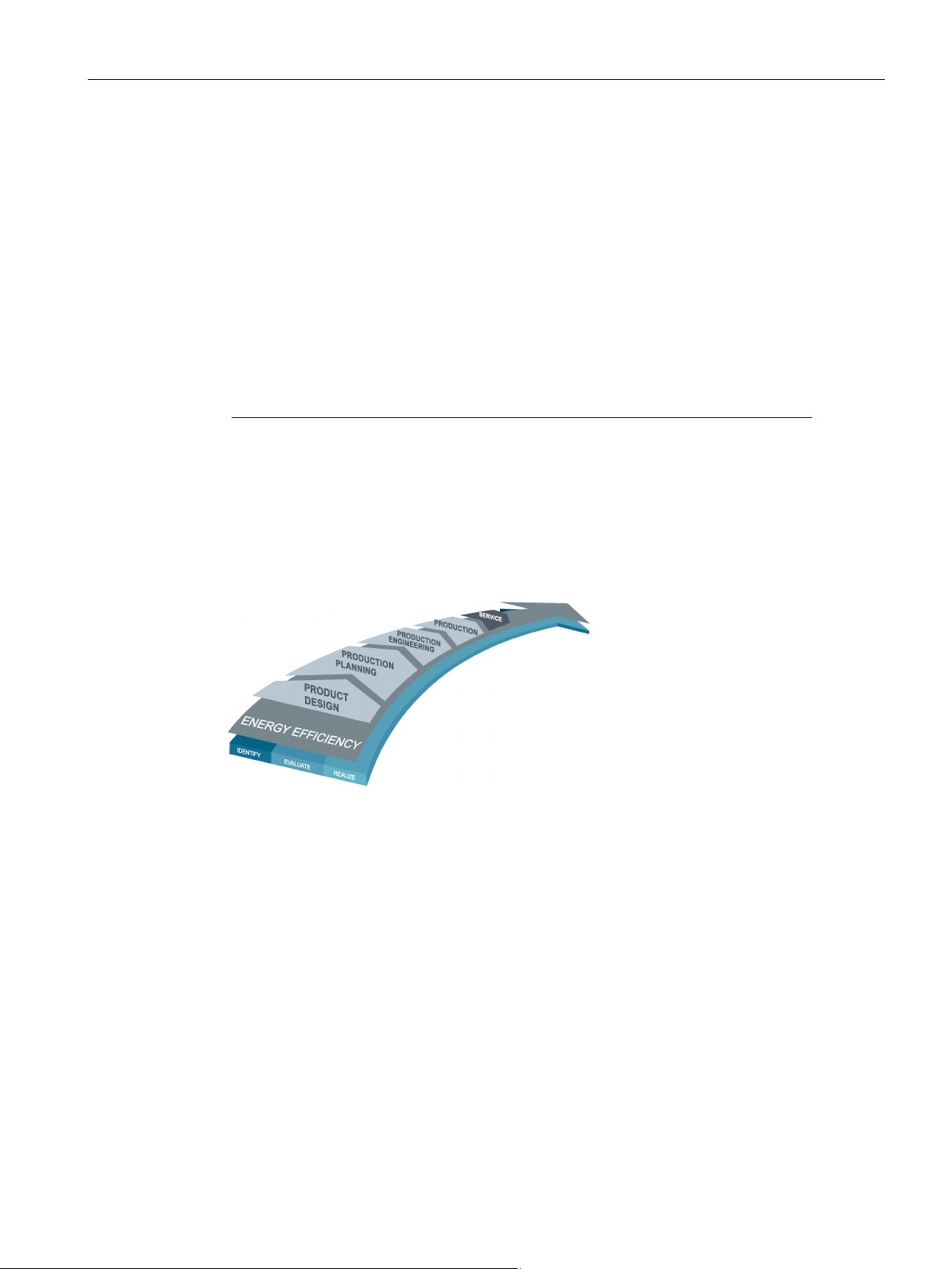
1.3 Advantages through energy efficiency
Siemens offers you a unique portfolio for efficient energy management in industry – a
process that serves to optimally shape your energy requirement. Operational energy
management is subdivided into three phases:
● Identification
● Evaluation
● Realization
Siemens supports you with suitable hardware and software solutions in every phase of a
project.
More information can be found on the Internet
(http://www.automation.siemens.com/mcms/industrial-controls/en/energy-efficiency).
3RT contactors make the following contribution to energy efficiency in the overall plant:
● AC/DC coils with electrical control to reduce the closing power and holding power
● Smaller power supplies in the control circuit through low holding power at 24 V DC
● Reduced energy requirements of the contactors thanks to increased switching capacity in
each size from S00 to S3
Figure 1-1 Overview of the energy management process
To understand these operating instructions you should have a general knowledge of
automation engineering and low-voltage switchgear.
The manual is valid for these contactors and contactor assemblies. It contains a description
of the devices that is valid at the time of publication.
SIRIUS - SIRIUS 3RT Contactors/Contactor assemblies
Manual, 09/2017, A5E03656507120A/RS-AE/006
15

Introduction
1.6
Siemens Industry Online Support
Information and Service
Link:
Product support
FAQs
Manuals/operating instructions
Certificates
Characteristic curves
Product announcements
Downloads
Application examples
Technical data
Link:
1.6 Siemens Industry Online Support
In Siemens Industry Online Support, you can obtain up-to-date information from our global
support database quickly and simply. To accompany our products and systems, we offer a
wealth of information and services that provide support in every phase of the lifecycle of your
machine or plant – from planning and implementation, through commissioning, up to
maintenance and modernization:
● Product support
● Application examples
● Services
● Forum
● mySupport
Siemens Industry Online Support (https://support.industry.siemens.com/cs/ww/en)
You will find here all the information and comprehensive know-how covering all aspects of
your product:
●
Our answers to frequently asked questions.
●
Read online or download, available as PDF or individually configurable.
●
Clearly sorted according to approving authority, type and country.
●
For support in planning and configuring your system.
●
The latest information and news concerning our products.
●
You can find here updates, service packs, HSPs and much more for your product.
●
Function blocks, background and system descriptions, performance statements,
demonstration systems, and application examples, clearly explained and represented.
●
Technical product data for support in planning and implementing your project.
Product support (https://support.industry.siemens.com/cs/ww/en/ps)
SIRIUS - SIRIUS 3RT Contactors/Contactor assemblies
16 Manual, 09/2017, A5E03656507120A/RS-AE/006

Introduction
mySupport
Personal messages
Inquiries
Notifications
Filters
Favorites / Tags
Entries last viewed
Documentation
Personal data
CAx data
1.7
Further documentation
1.7 Further documentation
With "mySupport", your personal workspace, you get the very best out of your Industry
Online Support. Everything to enable you to find the right information every time.
The following functions are now available:
●
Your personal mailbox for exchanging information and managing your contacts
●
Use our online form for specific solution suggestions, or send your technical inquiry
directly to a specialist in Technical Support
●
Make sure you always have the latest information - individually tailored to your needs
●
Simple management and re-use of your filter settings from Product Support and the
Technical Forum
●
Create your own knowledge database by assigning "Favorites" and "Tags" to documents
– simply and efficiently
●
Clear presentation of your last viewed entries
●
Configure your individual documentation from different manuals – quickly and without
complications
●
Change personal data and contact information here
●
Simple access to thousands of items of CAx data such as 3D models, 2D dimension
drawings, EPLAN macros and much more
SIRIUS - SIRIUS 3RT Contactors/Contactor assemblies
Manual, 09/2017, A5E03656507120A/RS-AE/006
To install and connect the contactors and contactor assemblies, you require the operating
instructions of the contactors and contactor assemblies used.
You can find a list of operating instructions and an overview of the manuals pertaining to the
SIRIUS modular system in the Appendix "References (Page 495)".
17

Introduction
1.8
DataMatrix code
1P Article
number
+ S Loc
/ Date
Serial numbe
Data
identifier
User content
Separ
User content
Separ
User content
User content
Note
The information content is displayed without spaces.
1.9
Siemens Industry Online Support app
Siemens Industry Online Support app
Link for Android
Link for iOS
Link for Windows Phone
1.8 DataMatrix code
A Data Matrix code has been lasered onto the contactors and contactor assembly
enclosures.
The Data Matrix codes are standardized in ISO/IEC 16022. The Data Matrix codes on
Siemens devices use ECC200 coding for powerful error correction.
The following information is stored in the Data Matrix code:
ation
ator
ator
r
This machine-readable information simplifies and accelerates handling of the respective
devices.
As well as fast access to the serial numbers of the respective devices for unique
identification, the Data Matrix codes simplify communication with Siemens Technical
Support.
You can use the Siemens Industry Online Support app to access all the device-specific
information available on the Siemens Industry Online Support portal for a particular article
number, including operating instructions, manuals, datasheets, FAQs etc.
The Siemens Industry Online Support app is available for iOS, Android or Windows Phone
devices. You can download the app from the following links:
SIRIUS - SIRIUS 3RT Contactors/Contactor assemblies
18 Manual, 09/2017, A5E03656507120A/RS-AE/006

Introduction
1.10
Recycling and disposal
1.11
Technical Assistance
Up-to-the-minute information
Technical Assistance:
or on the Internet at:
1.10 Recycling and disposal
These devices can be recycled thanks to their low pollutant content. For environmentallyfriendly recycling and disposal of your electronic waste, please contact a company certified
for the disposal of electronic waste.
You can obtain further assistance by calling the following numbers:
Telephone: +49 (911) 895-5900 (8 a.m. to 5 p.m. CET)
Fax: +49 (911) 895-5907
E-mail: (mailto:technical-assistance@siemens.com)
Internet: (http://www.siemens.com/sirius/technical-assistance)
SIRIUS - SIRIUS 3RT Contactors/Contactor assemblies
Manual, 09/2017, A5E03656507120A/RS-AE/006
19

Introduction
1.11 Technical Assistance
SIRIUS - SIRIUS 3RT Contactors/Contactor assemblies
20 Manual, 09/2017, A5E03656507120A/RS-AE/006

2
2.1
Standards and product approvals
Applicable regulations, standards, and approvals
Note
Depending on meaning, some standards and approvals are applied only to specific product
variants and are restricted to these. For example, the IEC
account only for contactors for rail applications but not for standard contactors.
Standard / approvals
Description
Note
General rules
starters
devices
components - General rules
for design
safety-related systems
programmable electronic control systems
Below is a list of extracts from the most important standards and approvals of the 3RT and
3RH contactors.
60077-2 standard is taken into
IEC 60947-1 Low-voltage switchgear and controlgear -
IEC 60947-4-1 Low-voltage switchgear and controlgear Part
4-1: Electromechanical contactors and motor-
IEC 60947-5-1 Low-voltage switchgear and controlgear Part
5-1: Control circuit devices and switching
elements - Electromechanical control circuit
IEC 60077-2 Railway applications - Electric equipment for
rolling stock - Part 2: Electrotechnical
EN ISO 13849-1 Safety of machinery – safety-related parts of
control systems - Part 1: General principles
IEC 61508 Functional safety of
electrical/electronic/programmable electronic
IEC 62061 Safety of machinery - Functional safety of
safety-related electrical, electronic and
Main approval for IEC-orientated international
markets
Relevant for auxiliary circuits and 3RH contactor
relays
Additional approval for railroad applications
Approvals for use in safety-related applications
SIRIUS - SIRIUS 3RT Contactors/Contactor assemblies
Manual, 09/2017, A5E03656507120A/RS-AE/006
21

Standards
Standard / approvals
Description
Note
Part 1: General rules
starters
CSA-C22.2 No. 14-13
Industrial Control Equipment
No 60947-1-13
Part 1: General rules
starters
Certification
Reference
Reference
2.1 Standards and product approvals
UL 60947-1 Low-Voltage Switchgear and Control gear -
UL 60947-4-1 Low-Voltage Switchgear and Control gear -
Part 4-1: Contactors and motor-starters Electromechanical contactors and motor-
CAN/CSA-C22.2
CAN/CSA-C22.2
No 60947-4-1-14
CCC Certificate for China Compulsory Product
Low-Voltage Switchgear and Control gear -
Low-Voltage Switchgear and Control gear Part 4-1: Contactors and motor-starters Electromechanical contactors and motor-
SIRIUS components have been approved by a whole range of bodies for various sectors
(shipbuilding, etc.). More information and certificates for download are available on the
Internet (https://support.industry.siemens.com/cs/ww/en/ps/16131/cert).
Approvals for the UL market, predominantly the
USA
Approvals specifically for the Canadian market
Approval specifically for the Chinese market
You can find all the technical data and other information regarding the products in the
Siemens Industry Online Support
(https://support.industry.siemens.com/cs/ww/en/ps/16132/td).
SIRIUS - SIRIUS 3RT Contactors/Contactor assemblies
22 Manual, 09/2017, A5E03656507120A/RS-AE/006

Standards
2.2
Protective separation
Definition
Protective separation for 3RT10, 3RT20 and 3RH2 contactor relays
Regulations
2.2 Protective separation
In order for the "protective separation" of circuits to be achieved, an individual fault must not
be able to trigger a voltage overspill from one circuit into another. The kinds of fault to be
taken into account include twisted or loose conductive parts, twisted solder pins, broken
winding wires, missing screws, or broken barriers within a device.
The term "protective separation" is used in relation to safety extra low voltage (SELV/PELV)
and functional extra low voltage (FELV). Protective separation reliably prevents a dangerous
contact voltage from spilling over to the voltage which has been protectively separated
(e.g. to a safety extra low voltage which is present or switched in the same device). If the
current paths of a contactor are operated at different voltages, "protective separation"
requirements must be met. With 3RT1 and 3RT2 contactors, and 3RH2 contactor relays,
"protective separation" is ensured up to a certain voltage.
"Protective separation" between circuits within equipment is achieved by complying with the
basic requirements contained in the IEC 60947-1 standard.
Basic requirements include, for example:
● Double or reinforced insulation
● Electrically protective shielding
● Combination of double or reinforced insulation and electrically protective shielding
The insulation must be resistant to aging for the duration of the expected service life.
Circuits without a safety extra low voltage or a functional extra low voltage do not require
protective separation.
SIRIUS - SIRIUS 3RT Contactors/Contactor assemblies
Manual, 09/2017, A5E03656507120A/RS-AE/006
23
Standards
2.3
Positively driven contact elements/Mirror contacts
Positively driven contacts for contactor relays according to IEC 60947-5-1
Mirror contact for power contactors to IEC 60947-4-1
Note
Both contact characteristics, the
well as the mirror contact in the power contactor, meet the same technical requirements.
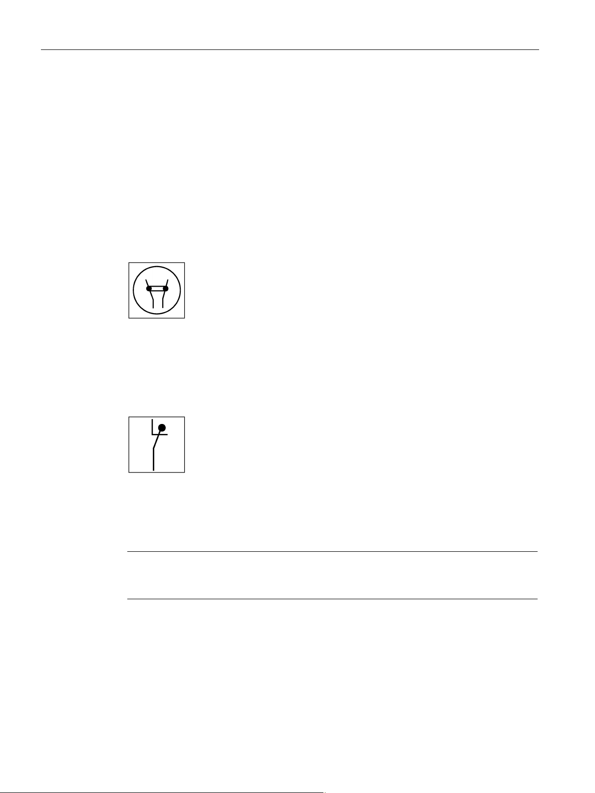
2.3 Positively driven contact elements/Mirror contacts
Positively-driven contact elements according to IEC 60947-5-1 are a combination of "n" NO
contacts and "m" NC contacts which are designed in such a way that they cannot be closed
simultaneously. "Positively driven operation" may only apply to auxiliary switch elements
which are contained in switching devices and whose actuating forces are generated
internally. An example of such elements are the SIRIUS 3RH2 contactor relays.
All SIRIUS 3RH2 contactor relays (with at least 1 NC contact) are tested to IEC 60947-5-1,
and ever since the product was launched, they have featured positively driven contact
elements in the basic device, or in the basic device in conjunction with auxiliary switches.
Figure 2-1 Symbol for positively driven contact elements in a switching device
A mirror contact according to IEC 60947-4-1 is an auxiliary NC contact that cannot be closed
simultaneously with an NO main contact.
Figure 2-2 Symbol for mirror contacts in a switching device
All SIRIUS 3RT1 / 3RT2 motor contactors (with at least 1 NC auxiliary contact) are tested to
IEC 60947-4-1 and have featured mirror contact characteristics in conjunction with auxiliary
switches ever since the product was launched.
positively driven contact element in the contactor relay as
The 3RT1 / 3RT2 / 3RH2 contactors are suitable for applications in the safety circuit. For
contactor relays, this applies on account of the positively driven operation of the contacts.
For motor contactors, it applies on account of the mirror contact properties of the auxiliary
contacts.
SIRIUS - SIRIUS 3RT Contactors/Contactor assemblies
24 Manual, 09/2017, A5E03656507120A/RS-AE/006

Standards
Employer's Liability Insurance Association / SUVA
Note
The SUVA certificate is required if products or systems are operated in Switzerland.
2.4
Used for stop category 0 / 1
Used for stop category 0 / stop category 1
2.4 Used for stop category 0 / 1
In addition to the standards IEC 60947-4-1 and IEC 60947-5-1, the requirements of the
German Employer's Liability Insurance Associations or the Swiss Accident Insurance
Institute (SUVA) also apply in the case of safety circuits for the protection of personnel.
These requirements set stricter conditions for devices with mirror contacts or positively
driven contact elements. The basic SUVA requirement is that all auxiliary switches must be
mounted on the basic device at the factory in such a way that they cannot be removed.
Manual actuation of the contactor must not be possible.
A SUVAPro type-examination certificate confirms that the switching device meets the basic
health and safety requirements and that this requirement agreement has been assessed by
an accredited European Notified Body.
All SIRIUS 3RH2 contactor relays (with at least 1 NC auxiliary contact) are tested according
to IEC 60947-5-1 and have possessed the SUVA type-examination certificate since product
launch.
All SIRIUS 3RT2 motor contactors (with at least 1 NC contact) are tested according to
IEC 60947-4-1 and can be supplied in accordance with SUVA requirements.
Thanks to use of a double bridge for the contacts, all 3RT2 motor contactors and
3RH2 contactor relays feature contact redundancy and optimization of the contact surface.
This crucially enhances the contactors' contact reliability.
The 3RT1 contactors are also available with non-removable lateral auxiliary switches.
All SIRIUS 3RT1, 3RT2 and 3RH2 contactors with mirror contacts / positively driven contacts
are generally suitable for use in safety circuits according to stop category 0 / stop category 1.
SIRIUS - SIRIUS 3RT Contactors/Contactor assemblies
Manual, 09/2017, A5E03656507120A/RS-AE/006
25
Standards
2.5
IE3 / IE4 ready
Note
Using 3RT contactors with IE3 / IE4 motors
For the use of 3RT contactors in conjunction with highly energy
please observe the information on dimensioning and configuring in the "Application Manual
SIRIUS Controls with IE3
(
2.5 IE3 / IE4 ready
Ambitious climate protection goals in Europe call for increasingly energy-efficient
components.
With this in mind, the energy efficiency class IE3 / IE4 has been mandatory since January
2015 (with exceptions) for three-phase asynchronous motors, and this will have an effect on
motors, low-voltage power distribution systems, and industrial controls.
This applies:
● Since January 1, 2015 for motors from 7.5 kW to 375 kW
● From January 1, 2017 for motors from 0.75 kW to 375 kW
You will be optimally equipped for the current motor generation with the SIRIUS modular
system components and 3VA molded case circuit breakers.
You will find information on IE3 / IE4 at:
Information IE3 (http://www.siemens.com/IE3ready)
-efficient IE3 / IE4 motors,
-
/ IE4 Motors
https://support.industry.siemens.com/cs/ww/en/view/94770820)".
SIRIUS - SIRIUS 3RT Contactors/Contactor assemblies
26 Manual, 09/2017, A5E03656507120A/RS-AE/006

Standards
2.6
Applications
Use and application areas
2.6 Applications
Various different switching devices are available for switching electrical loads. When
frequent switching is necessary, the contactor is the ideal device.
Contactors are the most commonly used switching devices in industry, mechanical
engineering and switchgear construction. The progressive automation of production plants
has increased the significance of contactors, but this is also associated with higher and
sometimes different requirements.
An automatic production system is significantly more sensitive to operating faults than
manually operated systems. Every fault on an electrical device means a standstill,
production downtime, and often substantial costs for recommissioning.
For this reason, value was placed on high operational reliability in the development of the
SIRIUS contactor series. High service life, high contact reliability, and the option of using the
contactors in the control cabinet at higher ambient temperatures are among the factors
contributing to this. The contactors can be used at up to 60 °C and without derating even
with side-by-side mounting.
Due to the diverse range application options, the range of contactors also encompasses
versions for special applications such as switching resistive loads or switching capacitors, as
well as the main 3RT20 and 3RT10 series for switching motorized loads. Besides the
contactor versions for various load types, there are also special versions for specific areas of
application with extended operating range and special additional approvals for rail
applications or for fail-safe control in safety applications.
The different contactor series with their possible application areas are explained in the
following subsections.
SIRIUS - SIRIUS 3RT Contactors/Contactor assemblies
Manual, 09/2017, A5E03656507120A/RS-AE/006
27

Standards
Utilization categories
Utilization categories
AC
Main circuit contacts: Utilization category for AC voltages
AC-2
Slip-ring motors: starting, switching off
AC-3
Squirrel-cage motors: starting, switching-off motors during running
AC-4
Squirrel-cage motors: starting, plugging, inching
AC-5a
Switching of discharge lamp controls
AC-5b
Switching of incandescent lamps
AC-6a
Switching of transformers
AC-6b
Switching of capacitive loads
DC
Main circuit contacts: Utilization category for DC voltages
DC-1
Non-inductive or slightly inductive loads, resistance furnaces
DC-3
Shunt-wound motors: Starting, plugging, reversing, inching, dynamic braking
DC-5
Series-wound motors: Starting, plugging, reversing, inching, dynamic braking
AC
Auxiliary circuit contacts: Utilization category for AC voltages
AC-12
Control of resistive loads and solid-state loads with isolation by opto couplers
AC-14
Control of small electromagnetic loads (max. 72 VA)
AC-15
Control of electromagnetic loads (over 72 VA)
DC Auxiliary circuit contacts: Utilization category for DC voltages
DC-12
Control of resistive loads and solid-state loads with isolation by opto couplers
DC-13
Control of electromagnets
2.6 Applications
According to IEC 60947-4-1, the application area of and the load applied to power contactors
can be identified by looking at the specified utilization category in conjunction with the
specified rated operational current or the motor power and the rated voltage. The table below
lists the most important utilization categories for contactors.
AC-1 Non-inductive or slightly inductive loads, resistance furnaces
SIRIUS - SIRIUS 3RT Contactors/Contactor assemblies
28 Manual, 09/2017, A5E03656507120A/RS-AE/006
3
3.1
General safety notes
DANGER
Hazardous voltage.
Will cause death or serious injury.
Electromagnetic compatibility (EMC)
Note
EMC Environment A
The 3RT / 3RH cont
Environment
Use of these products in Environment
in which case the user may be required to take adequate mitigation measures.
Turn off and lock out all power supplying this device before working on this device.
The 3RT / 3RH contactors with electronic operating mechanism have been designed for
Environment A according to IEC 60947-1, IEC 60947-4-1 and Class A according to
CISPR 11, EN 55011.
A.
actors with electronic operating mechanism have been designed for
B may cause unwanted electromagnetic disturbances
SIRIUS - SIRIUS 3RT Contactors/Contactor assemblies
Manual, 09/2017, A5E03656507120A/RS-AE/006
29

Safety instructions
3.2
Intended use
WARNING
Hazardous Voltage
Can Cause Death or Serious Injury.
Use of hardware products for intended purpose
3.3
Current information about operational safety
Important note for maintaining operational safety of your system
3.2 Intended use
This equipment is only allowed to be used for the applications described in the catalog and
in the technical description, and only in conjunction with non-Siemens equipment and
components recommended by Siemens.
Correct transport, storage, installation and assembly, as well as careful operation and
maintenance, are required to ensure that the product operates safely and without faults.
Before you run any sample programs or programs you have written yourself, make sure
that running the plant cannot cause injury to anyone else or damage to the machine itself.
EU note regarding machine safety: Start-up/commissioning is absolutely prohibited until it
has been ensured that the machine in which the component described here is to be
installed fulfills the regulations/specifications of Directive 2006/42/EC.
Please take note of our latest information.
Systems with safety-related characteristics are subject to special operational safety
requirements on the part of the operator. The supplier is also obliged to comply with special
product monitoring measures. For this reason, we publish a special newsletter containing
information on product developments and features that are (or could be) relevant to
operation of safety-related systems. By subscribing to the appropriate newsletter, you will
ensure that you are always up-to-date and able to make changes to your system, when
necessary:
SIEMENS newsletter (http://www.industry.siemens.com/newsletter)
Sign on to the following newsletter under "Products & Solutions":
● Industrial Controls - SIRIUS News (en)
SIRIUS - SIRIUS 3RT Contactors/Contactor assemblies
30 Manual, 09/2017, A5E03656507120A/RS-AE/006
 Loading...