

Siemens SIRIUS 3RM1,SIRIUS 3RM10,SIRIUS 3RM11,SIRIUS 3RM12,SIRIUS 3RM13 User Manual
Industrial Controls
Load Feeders and Motor Starters
SIRIUS 3RM1 Motor Starter
Manual
Edition 06/2016
siemens.com


SIRIUS 3RM1 motor starter
___________________
___________________
___________________
___________________
___________________
___________________
___________________
___________________
___________________
___________________
___________________
___________________
___________________
Industrial Controls
Load feeders and motor starters
SIRIUS 3RM1 motor starter
Manual
06/2016
A5E0345285095020A/RS
Introduction
1
Product-specific safety
information
2
Description
3
Configuration
4
Mounting
5
Connection
6
Operator control and
monitoring
7
Service and maintenance
8
Technical data
9
Dimension drawings
10
Circuit diagrams
11
Typical circuits
A
Directives
B
-AE/005

Siemens AG
Division Digital Factory
Postfach 48 48
90026 NÜRNBERG
GERMANY
3ZX1012-0RM10-2AC1
Ⓟ
Copyright © Siemens AG 2012.
All
Legal information
Warning notice system
DANGER
indicates that death or severe personal injury will result if proper precautions are not taken.
WARNING
indicates that death or severe personal injury may result if proper precautions are not taken.
CAUTION
indicates that minor personal injury can result if proper precautions are not taken.
NOTICE
indicates that property damage can result if proper precautions are not taken.
Qualified Personnel
personnel qualified
Proper use of Siemens products
WARNING
Siemens products may only be used for the applications described in the catalog and in the relevant technical
ambient conditions must be complied with. The information in the relevant documentation must be observed.
Trademarks
Disclaimer of Liability
This manual contains notices you have to observe in order to ensure your personal safety, as well as to prevent
damage to property. The notices referring to your personal safety are highlighted in the manual by a safety alert
symbol, notices referring only to property damage have no safety alert symbol. These notices shown below are
graded according to the degree of danger.
If more than one degree of danger is present, the warning notice representing the highest degree of danger will
be used. A notice warning of injury to persons with a safety alert symbol may also include a warning relating to
property damage.
The product/system described in this documentation may be operated only by
task in accordance with the relevant documentation, in particular its warning notices and safety instructions.
Qualified personnel are those who, based on their training and experience, are capable of identifying risks and
avoiding potential hazards when working with these products/systems.
Note the following:
documentation. If products and components from other manufacturers are used, these must be recommended
or approved by Siemens. Proper transport, storage, installation, assembly, commissioning, operation and
maintenance are required to ensure that the products operate safely and without any problems. The permissible
All names identified by ® are registered trademarks of Siemens AG. The remaining trademarks in this publication
may be trademarks whose use by third parties for their own purposes could violate the rights of the owner.
We have reviewed the contents of this publication to ensure consistency with the hardware and software
described. Since variance cannot be precluded entirely, we cannot guarantee full consistency. However, the
information in this publication is reviewed regularly and any necessary corrections are included in subsequent
editions.
for the specific
06/2016 Subject to change
rights reserved

Table of contents
1 Introduction ........................................................................................................................................... 11
2 Product-specific safety information ........................................................................................................ 19
3 Description ............................................................................................................................................ 25
1.1 Responsibility of the user for system configuration and functionality ..................................... 11
1.2 Required basic knowledge ...................................................................................................... 11
1.3 Scope ...................................................................................................................................... 12
1.4 Definition ................................................................................................................................. 12
1.5 Conformity ............................................................................................................................... 12
1.6 Further documentation ............................................................................................................ 13
1.7 Siemens Industry Online Support ........................................................................................... 14
1.8 DataMatrix code ...................................................................................................................... 16
1.9 Quick navigation ..................................................................................................................... 17
2.1 General safety notes ............................................................................................................... 19
2.2 Safety information for hazardous areas .................................................................................. 20
2.3 Safety instructions for safety-related applications .................................................................. 21
2.4 Intended use ........................................................................................................................... 23
2.5 Current information about operational safety ......................................................................... 23
2.6 Declaration of conformity ........................................................................................................ 24
3.1 Overview ................................................................................................................................. 25
3.2 Applications ............................................................................................................................. 26
3.3 Hybrid technology ................................................................................................................... 27
3.4 Device versions ....................................................................................................................... 29
3.5 Functions ................................................................................................................................ 32
3.5.1 Switching the 3RM1 motor starter under normal operating conditions ................................... 32
3.5.1.1 Direct-on-line starter ............................................................................................................... 33
3.5.1.2 Reversing starter ..................................................................................................................... 34
3.5.2 Protective functions ................................................................................................................. 35
3.5.2.1 Overload protection ................................................................................................................. 35
3.5.2.2 Equipment protection .............................................................................................................. 35
3.5.2.3 Phase failure protection .......................................................................................................... 35
3.5.2.4 Asymmetry monitoring ............................................................................................................ 36
3.5.2.5 Thermal calculation method (motor memory module) ............................................................ 37
3.5.2.6 ATEX-certified motor overload protection in the case of 3RM11/3RM13 Failsafe ................. 38
SIRIUS 3RM1 motor starter
Manual, 06/2016, A5E0345285095020A/RS-AE/005
5

Table of contents
4 Configuration ........................................................................................................................................ 57
3.5.3 Shutdown on malfunction ....................................................................................................... 42
3.5.4 Safety-related shutdown with 3RM11/3RM13 Failsafe motor starters .................................. 43
3.5.4.1 Safety-related shutdown via the control supply voltage ........................................................ 44
3.5.5 Carrying out the function test ................................................................................................. 45
3.6 Accessories and article number scheme ............................................................................... 47
3.6.1 Overview of all device components ....................................................................................... 47
3.6.2 Accessories ............................................................................................................................ 48
3.6.2.1 Infeed system ......................................................................................................................... 48
3.6.2.2 Fuse module .......................................................................................................................... 49
3.6.2.3 Sealable cover ....................................................................................................................... 51
3.6.2.4 Wall mounting ........................................................................................................................ 51
3.6.2.5 Device connectors ................................................................................................................. 52
3.6.2.6 Terminals ............................................................................................................................... 55
3.6.2.7 Device identification label ...................................................................................................... 55
3.6.3 Article number scheme for SIRIUS 3RM1 motor starter ........................................................ 56
4.1 Rated operational current ...................................................................................................... 57
4.2 Derating at high installation altitudes (> 2 000 m) ................................................................. 58
4.3 Derating with high motor starting current ............................................................................... 59
4.4 Derating with high ambient temperature ................................................................................ 60
4.4.1 Maximum ambient temperature for 3RM1.01 (0.5 A) and 3RM1.02 (2 A) ............................. 60
4.4.2 Derating for 7 A devices ......................................................................................................... 60
4.5 Ambient conditions ................................................................................................................. 63
4.5.1 Application environment ......................................................................................................... 63
4.5.2 Ambient temperature ............................................................................................................. 63
4.5.3 Mounting position ................................................................................................................... 63
4.5.4 Grounding measures ............................................................................................................. 68
4.5.5 Permissible operating voltage ................................................................................................ 68
4.5.6 Minimum load current ............................................................................................................ 68
4.6 Load feeders - protection against short circuit ....................................................................... 69
4.6.1 Protection against short circuit ............................................................................................... 69
4.6.2 Configuration of load feeders ................................................................................................. 69
4.6.3 Configuration of a load feeder with 3RM1 motor starter in compliance with IEC .................. 69
4.6.3.1 Fuseless design ..................................................................................................................... 70
4.6.3.2 Fused design .......................................................................................................................... 71
4.6.4 Configuration of a load feeder with 3RM1 motor starter in compliance with UL .................... 73
4.6.4.1 Function according to UL 508 ................................................................................................ 73
4.6.4.2 Configuration of individual load feeders ................................................................................. 73
4.6.4.3 Configuring a group of load feeders (group installation) ........................................................ 76
4.7 Infeed for the main circuit ....................................................................................................... 79
4.7.1 Infeed options......................................................................................................................... 79
4.7.2 3RM19 3-phase infeed system .............................................................................................. 79
4.7.3 3RM193 fuse module ............................................................................................................. 81
4.8 Configuration with device connectors .................................................................................... 82
4.9 Examples/applications ........................................................................................................... 83
4.9.1 Operation with the EMERGENCY-STOP function ................................................................. 83
SIRIUS 3RM1 motor starter
6 Manual, 06/2016, A5E0345285095020A/RS-AE/005

Table of contents
5 Mounting ............................................................................................................................................... 87
6 Connection ......................................................................................................................................... 111
7 Operator control and monitoring .......................................................................................................... 125
5.1 Warning notices ...................................................................................................................... 87
5.2 Mounting the devices on a level surface................................................................................. 88
5.3 Disassembling the devices from a level surface ..................................................................... 89
5.4 Mounting the devices on a standard mounting rail ................................................................. 90
5.5 Mounting the devices on a fuse module ................................................................................. 91
5.6 Disassembling devices from a fuse module ........................................................................... 92
5.7 Mounting the fuse module ...................................................................................................... 93
5.8 Dismantling the fuse module .................................................................................................. 95
5.9 Modifying the fuse module to a 1-pole connection ................................................................. 96
5.10 Disassembling devices from a standard mounting rail ........................................................... 98
5.11 Mounting the devices with device connectors on a standard mounting rail ........................... 99
5.12 Disassembling the devices with device connectors from a standard mounting rail ............. 102
5.13 Mounting the devices with device connectors on a wall ....................................................... 105
5.14 Disassembling the devices with device connectors from a wall ........................................... 107
5.15 Mounting the sealable cover ................................................................................................. 109
6.1 Connecting the screw-type terminals .................................................................................... 111
6.2 Disconnecting the screw-type terminals ............................................................................... 113
6.3 Connecting the push-in terminals ......................................................................................... 114
6.3.1 Wiring rules for spring-loaded terminals (with push-in technology) ...................................... 114
6.3.2 Connecting the push-in terminals ......................................................................................... 115
6.4 Disconnecting the push-in terminals ..................................................................................... 117
6.5 Attaching the terminals ......................................................................................................... 118
6.6 Removing the terminals ........................................................................................................ 119
6.7 Connecting the infeed system (option) ................................................................................. 121
6.8 Connecting the fuse module (option) .................................................................................... 124
7.1 Operator controls .................................................................................................................. 125
7.1.1 Parameterizing the 3RM1 motor starter ................................................................................ 126
7.1.2 Setting the rated operational current .................................................................................... 126
7.1.3 Setting the RESET method ................................................................................................... 126
7.2 Displays and location of the connections.............................................................................. 128
7.2.1 Alarms, faults and system events ......................................................................................... 131
7.2.1.1 LEDs ..................................................................................................................................... 131
7.2.1.2 Status indicators of the 3RM1 motor starter ......................................................................... 131
7.2.1.3 Signaling faults on external I/O ............................................................................................. 133
7.2.1.4 Fault rectification ................................................................................................................... 134
SIRIUS 3RM1 motor starter
Manual, 06/2016, A5E0345285095020A/RS-AE/005
7

Table of contents
8 Service and maintenance ..................................................................................................................... 135
9 Technical data ..................................................................................................................................... 139
10 Dimension drawings ............................................................................................................................. 149
11 Circuit diagrams ................................................................................................................................... 159
A Typical circuits ..................................................................................................................................... 167
8.1 Maintenance and service ..................................................................................................... 135
8.2 Test interval for safety-related applications ......................................................................... 135
8.3 Device replacement ............................................................................................................. 136
8.4 Replacing the fuses in the 3RM19 fuse module .................................................................. 137
9.1 General technical data ......................................................................................................... 139
9.2 General safety data .............................................................................................................. 140
9.3 ATEX-specific safety data .................................................................................................... 140
9.4 Connection cross sections ................................................................................................... 141
9.5 Technical data in Siemens Industry Online Support ............................................................ 143
9.6 Number of starting operations .............................................................................................. 144
9.7 Overload protection/device protection characteristic ........................................................... 145
10.1 CAx data .............................................................................................................................. 149
10.2 Dimension drawings for 3RM1 device connectors ............................................................... 150
10.3 3RM1 dimension drawings ................................................................................................... 154
10.4 Dimension drawings 3RM19 fuse module ........................................................................... 157
11.1 CAx data .............................................................................................................................. 159
11.2 3RM10 circuit diagrams (direct-on-line starter, Standard) ................................................... 160
11.3 3RM11 circuit diagrams (direct-on-line starter, Failsafe) ..................................................... 162
11.4 3RM12 circuit diagrams (reversing starter, Standard) ......................................................... 163
11.5 3RM13 circuit diagrams (reversing starter, Failsafe) ........................................................... 165
A.1 Typical circuits for 3RM1 ...................................................................................................... 167
A.1.1 Direct-on-line starter 24 V DC with switch operation ........................................................... 167
A.1.2 Direct-on-line starter 24 V DC with switch operation and 230 V brake................................ 168
A.1.3 Direct-on-line starter 24 V DC with switch operation and 400 V brake................................ 169
A.1.4 Direct-on-line starter 24 V DC with switch operation and single-phase motor .................... 170
A.1.5 Direct-on-line starter with group protection, 24 V DC and PLC operation ........................... 171
A.1.6 Reversing starter 24 V DC with PLC operation ................................................................... 173
SIRIUS 3RM1 motor starter
8 Manual, 06/2016, A5E0345285095020A/RS-AE/005

Table of contents
B Directives ............................................................................................................................................ 187
Glossary ............................................................................................................................................. 189
Index................................................................................................................................................... 193
A.2 Typical circuits for safety-related shutdown .......................................................................... 174
A.2.1 General safety notes ............................................................................................................. 174
A.2.2 3SK1 safety relay with 3RM13 motor starter via device connector ...................................... 177
A.2.3 3SK1 safety relay wired with 3RM13 motor starter .............................................................. 179
A.2.4 3SK2 safety relay with 3RM11 motor starter via device connector ...................................... 181
A.2.5 3SK2 safety relay wired to 3RM11 motor starter .................................................................. 182
A.2.6 3RM13 reversing starter with PLC control, F-DO pp-switching ............................................ 183
A.2.7 3RM13 reversing starter with PLC control, F-DO pm-switching ........................................... 185
B.1 ESD Guidelines ..................................................................................................................... 187
SIRIUS 3RM1 motor starter
Manual, 06/2016, A5E0345285095020A/RS-AE/005
9

Table of contents
SIRIUS 3RM1 motor starter
10 Manual, 06/2016, A5E0345285095020A/RS-AE/005

1
1.1
Responsibility of the user for system configuration and functionality
1.2
Required basic knowledge
The SIRIUS 3RM1 motor starters described here have been developed to carry out
switching functions as part of a plant or machine.
The 3RM1 motor starters are available as direct-on-line starters in Standard design without
safety-related shutdown (3RM10) and in Failsafe design with safety-related shutdown
(3RM11 Failsafe), and also as reversing starters without safety-related shutdown (3RM12)
and in Failsafe design with safety-related shutdown (3RM13 Failsafe).
The following must be noted when using 3RM11 Failsafe/3RM13 Failsafe safety-related
motor starters:
A complete safety system consists of sensors, evaluation units, signaling devices and
methods for safety-related shutdown.
The manufacturer is responsible for ensuring safe overall functioning of a plant or machine
with safety-related components.
Siemens AG, its regional offices, and associated companies (hereinafter referred to as
"Siemens") cannot guarantee all the properties of an overall installation or machine that has
not been designed by Siemens.
Nor can Siemens assume liability for recommendations that appear or are implied in the
following description. No new guarantee, warranty, or liability claims beyond the scope of the
Siemens general terms of supply are to be derived or inferred from the following description.
A general knowledge of the following areas is needed in order to understand this manual:
● Industrial controls
● Digital circuitry
● Automation technology
● Safety engineering
SIRIUS 3RM1 motor starter
Manual, 06/2016, A5E0345285095020A/RS-AE/005
11

Introduction
1.3
Scope
1.4
Definition
1.5
Conformity
Standards
Approvals, test reports, characteristics
1.3 Scope
This manual is valid for SIRIUS 3RM1 motor starters. It contains a description of the motor
starter and its functions. It provides information about configuration, commissioning and
servicing. You will also find information on the infeed system, device connectors and further
accessories in the manual.
To facilitate configuration, the manual contains dimension drawings, circuit diagrams and
technical data of the system components.
SIEMENS reserves the right of including a Product Information for each new component,
and for each component of a later version.
In this manual, "3RM1 motor starter" always refers to all variants of the SIRIUS 3RM1 motor
starters.
All 3RM1 motor starters comply with the following standards:
● IEC 60947-4-2:2011-05
● IEC 60947-4-3:2011-07
The 3RM11 Failsafe and 3RM13 Failsafe motor starters also comply with the following
standards:
● EN 62061: 2005
● EN ISO 13849-1:2008
● IEC 61508-1:2010
● IEC 61508-2:2010
● IEC 61508-3:2010
Confirmation of approvals, test certificates and characteristic curves is available via the
Internet (http://www.siemens.com/sirius/approvals).
SIRIUS 3RM1 motor starter
12 Manual, 06/2016, A5E0345285095020A/RS-AE/005
Introduction
Degree of protection
DANGER
Hazardous voltage.
Will cause death or serious injury.
V, screw in all terminal screws that are not
1.6
Further documentation
Title of the manual
Article number1)
(https://support.industry.siemens.com/cs/ww/de/view/109444336)
1)
The manuals are available in the Service&Support Portal for downloading free of charge.
1.6 Further documentation
The 3RM1 motor starter's degree of protection is IP20.
The infeed system for the 3RM1 motor starter features IP20 degree of protection.
To ensure protection against an electric shock hazard with the hinged cover open at the
signaling contacts 95, 96, 98 at a voltage of ≥ 50
needed to clamp conductors.
Further documents that might be of interest for your configuration:
SIRIUS 3SK1 safety relays
(https://support.industry.siemens.com/cs/ww/de/view/67585885)
SIRIUS 3SK2 Safety Relays
3ZX1012-0SK11-0AC0
3ZX1012-0SK21-1AB1
SIRIUS 3RM1 motor starter
Manual, 06/2016, A5E0345285095020A/RS-AE/005
13

Introduction
1.7
Siemens Industry Online Support
Information and service
Link:
Product support
FAQs
Manuals/operating instructions
Certificates
Characteristics
Product announcements
Downloads
Application examples
Technical data
Link:
1.7 Siemens Industry Online Support
At Siemens Industry Online Support you can obtain up-to-date information from our global
support database quickly and simply. To accompany our products and systems, we offer a
wealth of information and services that provide support in every phase of the lifecycle of your
machine or plant – from planning and implementation and commissioning, right through to
maintenance and modernization:
● Product support
● Application examples
● Services
● Forum
● mySupport
Siemens Industry Online Support (https://support.industry.siemens.com/cs/ww/en/)
Here you will find all the information and comprehensive know-how for your product:
●
Our replies to frequently asked questions.
●
Read online or download, available as PDF or individually configurable.
●
Clearly sorted according to approving authority, type and country.
●
For support in planning and configuring your system.
●
The latest information and news concerning our products.
●
Here you will find updates, service packs, HSPs and much more for your product.
●
Function blocks, background and system descriptions, performance statements,
demonstration systems, and application examples, clearly explained and represented.
●
Technical product data for support in planning and implementing your project.
Product support (https://support.industry.siemens.com/cs/ww/en/ps)
SIRIUS 3RM1 motor starter
14 Manual, 06/2016, A5E0345285095020A/RS-AE/005

Introduction
mySupport
Personal Messages
Requests
Notifications
Filter
Favorites / Tagging
Entries last viewed
Documentation
Personal data
CAx data
Configurator
Link:
1.7 Siemens Industry Online Support
With "mySupport", your personal work area, you get the very best out of your Industry Online
Support experience. Everything enables you to find the right information - every time.
The following functions are now available:
●
Your personal mailbox for exchanging information and managing your contacts
●
Use our online form for specific solution suggestions, or send your technical inquiry
directly to a specialist in Technical Support
●
Make sure you always have the latest information - individually tailored to your needs
●
Simple management and re-use of your filter settings from Product Support and the
Technical Forum
●
Create your own knowledge database by assigning "Favorites" and "Tags" to documents
– simply and efficiently
●
Clear presentation of your last viewed entries
●
Configure your individual documentation from different manuals – quickly and without
complications
●
Change personal data and contact information here
●
Simple access to thousands of items of CAx data such as 3D models, 2D dimension
drawings, EPLAN macros, and much more
Various configurators are available on the Internet to assist you with configuration.
The configurator for 3RM1 motor starters and matching accessories is an easy-to-use
selection and configuration tool. You can select the individual components and plan your
system in accordance with your specific requirements. You can save your selection, export it
as a text file or you can order it directly.
The configurator automatically compiles a document list of the information available in
Service&Support for every component. You can use it as the basis for putting together your
system documentation.
Configurator (http://www.siemens.com/sirius/configurators)
SIRIUS 3RM1 motor starter
Manual, 06/2016, A5E0345285095020A/RS-AE/005
15

Introduction
1.8
DataMatrix code
1P
Article number
+
S
Serial number
Note
The information content is displayed without spaces.
SIEMENS Industry Support App
Link for Android
Link for iOS
Link for Windows phone
1.8 DataMatrix code
A DataMatrix code is lasered onto the lower terminal cover of all devices of this series.
DataMatrix codes are standardized in ISO/IEC 16022. The DataMatrix codes on Siemens
devices use ECC200 coding.
The following device information is encoded in the DataMatrix codes as a bit stream:
● Article number
● Serial number
This information is stored in the following format in the DataMatrix code:
Data identifier Net content Separator Data identifier Net content
This machine-readable information simplifies and accelerates handling of the respective
devices.
As well as fast access to the serial numbers of the respective devices for unique
identification, the DataMatrix codes simplify communication with Siemens Technical Support.
DataMatrix codes primarily enable extremely fast and convenient access to all devicespecific information relating to an article number in the SIEMENS Service&Support Portal
(https://support.industry.siemens.com/cs/ww/en/), such as operating instructions, manuals,
data sheets, FAQs, etc.
We provide the SIEMENS Industry Support app free for this purpose and it can be used on
most commercially available smart phones and tablets.
The SIEMENS Industry Support app is available for iOS and Android-based devices and can
be accessed via the following links:
SIRIUS 3RM1 motor starter
16 Manual, 06/2016, A5E0345285095020A/RS-AE/005

Introduction
1.9
Quick navigation
Note
Reading the manual
The quick navigation is provided to help you find important topics quickly. It does not a
substitute for reading the manual.
Always read the entire manual.
Configuring
Commissioning:
1.9 Quick navigation
● Functions (Page 32)
● Technical data (Page 139)
● Derating (temperature, installation altitude, installation) Rated operational current
(Page 57)
● Applications Operation with the EMERGENCY-STOP function (Page 83)
● Circuit diagrams (Page 159)
● Product-specific safety information (Page 19)
● Overload trip:
– Thermal calculation method (motor memory module) (Page 37)
– Setting the RESET method (Page 126)
● Terminal designations Terminals (Page 55)
● Also note the following: Number of startsNumber of starting operations (Page 144),
switching times Switching the 3RM1 motor starter under normal operating conditions
(Page 32), pausesTechnical data (Page 139), minimum current Rated operational current
(Page 57) and Minimum load current (Page 68)
● Diagnosis Alarms, faults and system events (Page 131)
● Fault rectification (Page 134)
● Terminal designation Terminals (Page 55)
● Connection method Device versions (Page 29) and Connection cross sections
(Page 141)
● Removable terminals Terminals (Page 55)
● Setting the rated operational current (Page 126)
SIRIUS 3RM1 motor starter
Manual, 06/2016, A5E0345285095020A/RS-AE/005
17

Introduction
Service:
1.9 Quick navigation
● Diagnosis Alarms, faults and system events (Page 131)
● Setting the rated operational current (Page 126)
● Removable terminals Terminals (Page 55)
● Terminal designation Terminals (Page 55)
FAQ (https://support.industry.siemens.com/cs/ww/en/view/81525494)
SIRIUS 3RM1 motor starter
18 Manual, 06/2016, A5E0345285095020A/RS-AE/005
2
2.1
General safety notes
DANGER
Hazardous voltage.
Will cause death or serious injury.
DANGER
Hazardous voltage.
Will cause death or serious injury.
V, screw in all terminal screws that are not
NOTICE
Damage caused by electrostatic charge
Turn off and lock out all power supplying this device before working on this device.
To ensure protection against an electric shock hazard with the hinged cover open at the
signaling contacts 95, 96, 98 at a voltage of ≥ 50
needed to clamp conductors.
When handling and installing the 3RM1 motor starters, ensure that the components are
protected from electrostatic charge. Changes to the system configuration and wiring are
only permissible in the voltage-free state.
Connection of 3RM11 / 3RM13 Failsafe motor starters is only permissible when the power
supply units (PELV and SELV) are switched off.
SIRIUS 3RM1 motor starter
Manual, 06/2016, A5E0345285095020A/RS-AE/005
19

Product-specific safety information
2.2
Safety information for hazardous areas
WARNING
Explosion hazard in Class I and Class II Hazardous Locations.
Lebensgefahr oder schwere Verletzungsgefahr.
2.2 Safety information for hazardous areas
The components of the 3RM1 motor starters are not suitable for installation in Class I and
Class II Hazardous Locations.
The device must be installed in a control cabinet with minimum degree of protection of
IP 4x.
Please contact your ATEX specialist.
You will find further information in Chapter "ATEX-certified motor overload protection in the
case of 3RM11/3RM13 Failsafe (Page 38)."
SIRIUS 3RM1 motor starter
20 Manual, 06/2016, A5E0345285095020A/RS-AE/005
Product-specific safety information
2.3
Safety instructions for safety-related applications
DANGER
Hazardous voltage.
Will cause death or serious injury.
WARNING
Loss of the safety function
Annual function test
WARNING
Loss of the safety function in the event of a fault in the case of 3RM11 / 3RM13 Failsafe
motor starters with 110 to 230 V AC/110 V DC control supply voltage.
Can cause death or serious injury.
WARNING
Loss of the safety function when using device connectors.
Can cause death or serious injury.
2.3 Safety instructions for safety-related applications
Turn off and lock out all power supplying this device before working on this device.
In continuous operation, the key safety values apply in the case of a function test interval
(state change of the outputs) ≤ 1 year.
• Actuate the connected sensors.
• Check their effect on the safety relay and the downstream actuators.
• Activate the safety relay via the connected sensors.
• Check their effect on the safety relay and the downstream actuators.
• Defective devices must be replaced.
The control signal for the control inputs in the case of 3RM11/3RM13 Failsafe motor
starters with 110 to 230 V AC control supply voltage must come from A1. Otherwise, the
safety function is bypassed in the event of a fault. Thus, only relay outputs are admissible
when using a PLC.
Do not use a separate control voltage. Only use the relay outputs when using a PLC.
When the product is operated with a 3SK safety relay and a device connector, the supply
voltage for 3RM1 motor starters is fed in via the device connectors.
In this case, do not connect anything to terminals A1 and A2 of the 3RM1 motor starters, in
order to prevent bypassing of the safety function.
SIRIUS 3RM1 motor starter
Manual, 06/2016, A5E0345285095020A/RS-AE/005
21
Product-specific safety information
WARNING
Loss of the safety function during hybrid operation of Failsafe and Standard motor starters.
Can cause death or serious injury.
WARNING
Loss of the safety function when the neutral conductor is connected to a load.
Can cause death or serious injury.
NOTICE
Electromagnetic interference
Note
SILCL 3 to EN 62061:2005, PL e/Cat. 4 to EN ISO 13849-1:2008
The 3RM11 Failsafe and 3RM13 Failsafe safety
a way as to allow implementation of safety
with EN
2.3 Safety instructions for safety-related applications
Hybrid operation of 3RM10/3RM12 Standard motor starters with 3RM11/3RM13 Failsafe
motor starters in safety-related applications is not admissible.
Only ever use safety-related motor starters (3RM11 Failsafe and 3RM13 Failsafe) in safetyrelated applications.
When using the 3RM11 Failsafe and 3RM13 Failsafe motor starters, note that no neutral
conductor may be connected if the load circuit contains 3-phase loads, e.g. a 230 V brake
or resistive loads.
The following must be grounded in accordance with regulations to ensure noise immunity of
the 3RM11 / 3RM13 Failsafe motor starters:
• PELV / SELV power supply units (please also note the documentation for the respective
power supply unit in this regard).
-related motor starters are designed in such
-related applications up to SILCL 3 in accordance
62061 and PL e/Cat. 4 in accordance with EN ISO 13849-1.
SIRIUS 3RM1 motor starter
22 Manual, 06/2016, A5E0345285095020A/RS-AE/005

Product-specific safety information
2.4
Intended use
WARNING
Improper use of hardware products.
Serious damage to property, can cause death or serious injury.
2.5
Current information about operational safety
Important note for maintaining operational safety of your system
2.4 Intended use
This equipment is only allowed to be used for the applications described in the catalog and
in the technical description, and only in conjunction with non-Siemens equipment and
components recommended by Siemens.
Correct transport, storage, installation and assembly, as well as careful operation and
maintenance, are required to ensure that the product operates safely and without faults.
EU note: Commissioning is absolutely prohibited until it has been ensured that the machine
in which the component described here is to be installed complies with the stipulations of
the Directive 2006/42/EC.
Please take note of our latest information.
Systems with safety-related characteristics are subject to special operational safety
requirements on the part of the operator. The supplier is also obliged to comply with special
product monitoring measures. For this reason, we publish a special newsletter containing
information on product developments and features that are (or could be) relevant to
operation of safety-related systems. By subscribing to the appropriate newsletter, you will
ensure that you are always up-to-date and able to make changes to your system, when
necessary:
Siemens newsletter (http://www.industry.siemens.com/newsletter)
Sign on to the following newsletter under "Products & Solutions":
● Control Components and System Engineering News
● Safety Integrated Newsletter
SIRIUS 3RM1 motor starter
Manual, 06/2016, A5E0345285095020A/RS-AE/005
23

Product-specific safety information
2.6
Declaration of conformity
2.6 Declaration of conformity
The manufacturer declares that the safety components of the 3RM1 motor starter series in
the designs marketed by us comply with the applicable basic health and safety requirements
of the EC Directives* stated (including amendments), and that the stated standards* were
applied in their design and construction.
* You can download the complete EC Declaration of Conformity from the Internet
(http://www.siemens.com/sirius/approvals) as a PDF.
SIRIUS 3RM1 motor starter
24 Manual, 06/2016, A5E0345285095020A/RS-AE/005
3
3.1
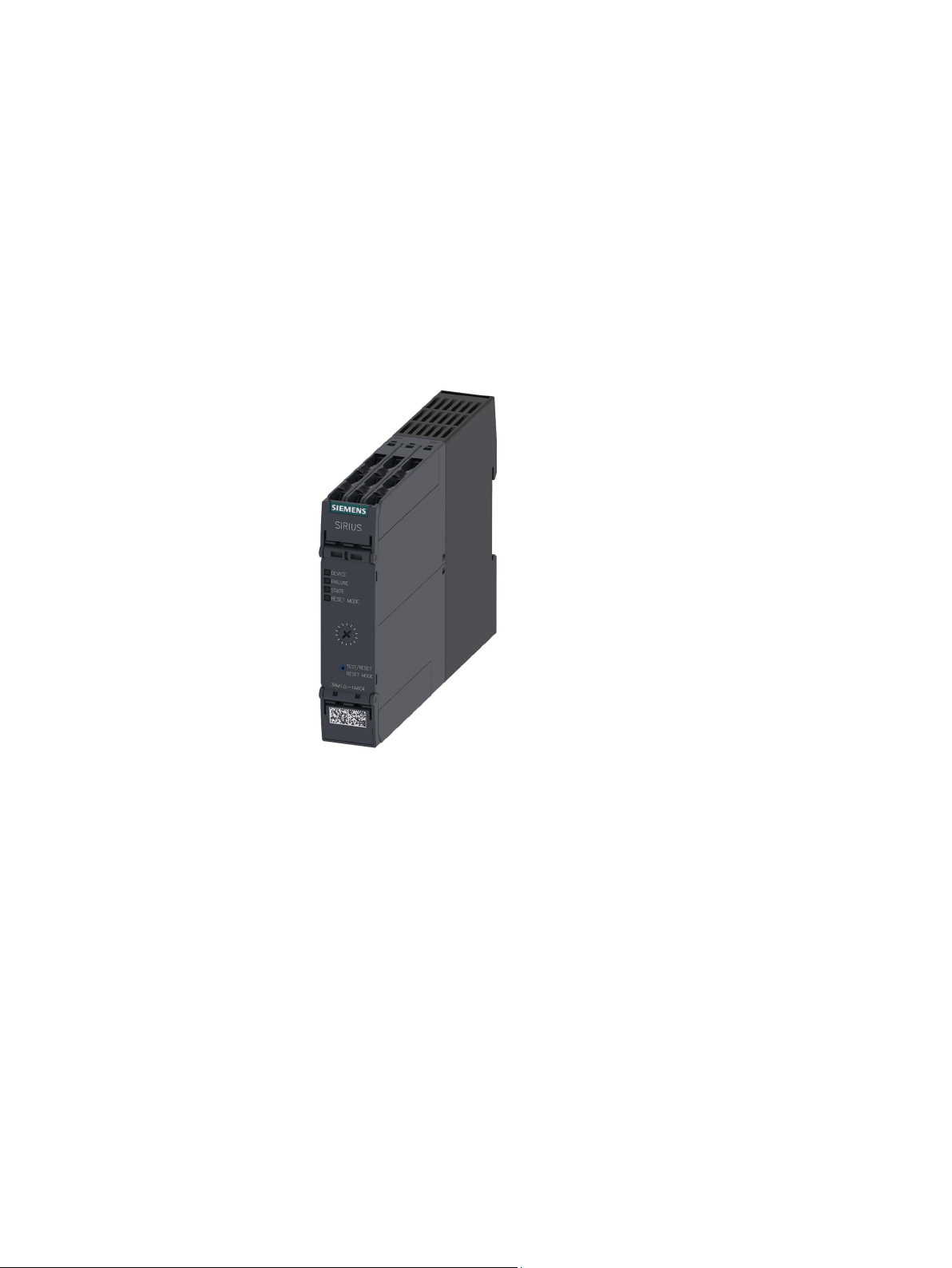
Overview
The 3RM1 motor starter is a compact device with a width of 22.5 mm. The 3RM1 motor
starter comprises combinations of relay contacts, power semiconductors, and a solid-state
overload relay for switching three-phase motors up to 3 kW (at 400 V) and resistive loads up
to 10 A (at AC voltages to 500 V) under normal operating conditions.
SIRIUS 3RM1 motor starter
Manual, 06/2016, A5E0345285095020A/RS-AE/005
25

Description
3.2
Applications
3.2 Applications
The 3RM1 motor starters can be used wherever combinations of contactors and overload
relays were previously used.
Thanks to the additional functionality of safety-related shutdown, the 3RM11 Failsafe and
3RM13 Failsafe motor starter variants are ideally suited to safety-related applications up to
SILCL 3 in accordance with EN 62061 and PL e/Cat. 4 in accordance with EN ISO 13849-1.
Short-circuit protection in a load feeder designed in this way must be implemented by
appropriate upstream short-circuit protection devices. These can be, for example, circuit
breakers or appropriate fuses.
You achieve maximum space-savings benefits by means of a group configuration of the
3RM1 motor starters. This enables several 3RM1 motor starters to be protected by one
short-circuit protection device.
The 3RM1 motor starters are used in the following areas, for example:
● Conveyor technology
● Logistics systems
● Production machines
● Machine tools
● Small elevators
SIRIUS 3RM1 motor starter
26 Manual, 06/2016, A5E0345285095020A/RS-AE/005

Description
3.3
Hybrid technology
Switching on
Current conducting
Switching off
3.3 Hybrid technology
The 3RM1 motor starter combines the benefits of semiconductor technology and relay
technology.
This combination is known as hybrid technology. The hybrid technology in the 3RM1 motor
starter is characterized by the following features:
The inrush current in the case of motorized loads is conducted briefly via the
semiconductors.
Advantage: The relay contacts are protected. Longer service life is achieved thanks to
reduced wear and tear.
The continuous current is conducted via relay contacts.
Advantage: Relay contacts cause less thermal losses than semiconductors.
Switch-off is implemented again via the semiconductor.
Advantage: The contacts are only slightly burdened by arcs. This results in increased service
life.
SIRIUS 3RM1 motor starter
Manual, 06/2016, A5E0345285095020A/RS-AE/005
27
Description
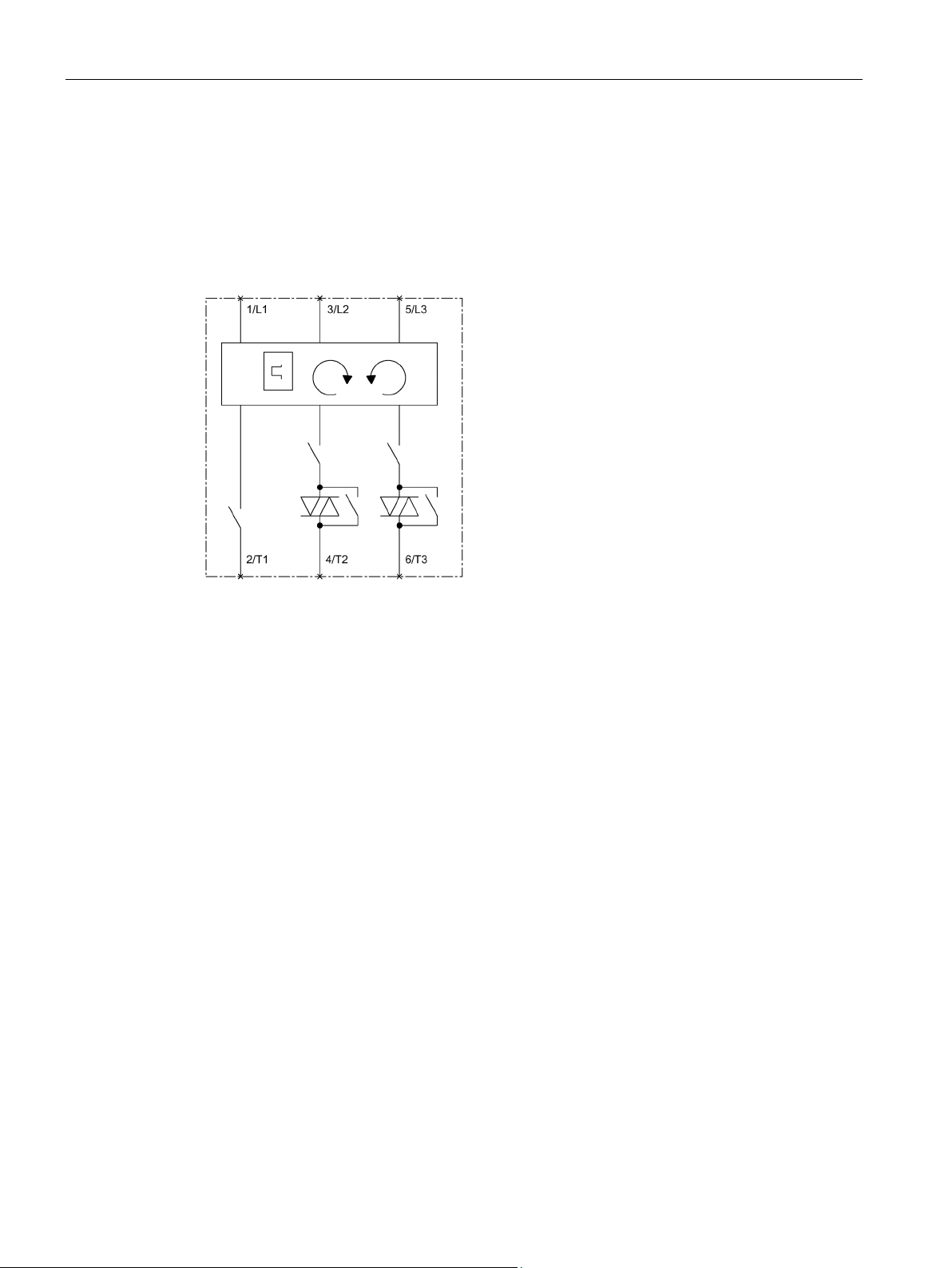
Circuit diagram
3.3 Hybrid technology
The semiconductors switch the motor on and off in two phases. In the switched-off state, all
three phases are opened by a relay contact.
To achieve the highest safety level SILCL 3 in accordance with EN 62061, PL e/Cat. 4 in
accordance with EN ISO 13849-1 in the case of 3RM11/3RM13 fail-safe motor starters,
further relay contacts are installed in series with the semiconductors.
Figure 3-1 Circuit diagram
SIRIUS 3RM1 motor starter
28 Manual, 06/2016, A5E0345285095020A/RS-AE/005
Description
3.4
Device versions
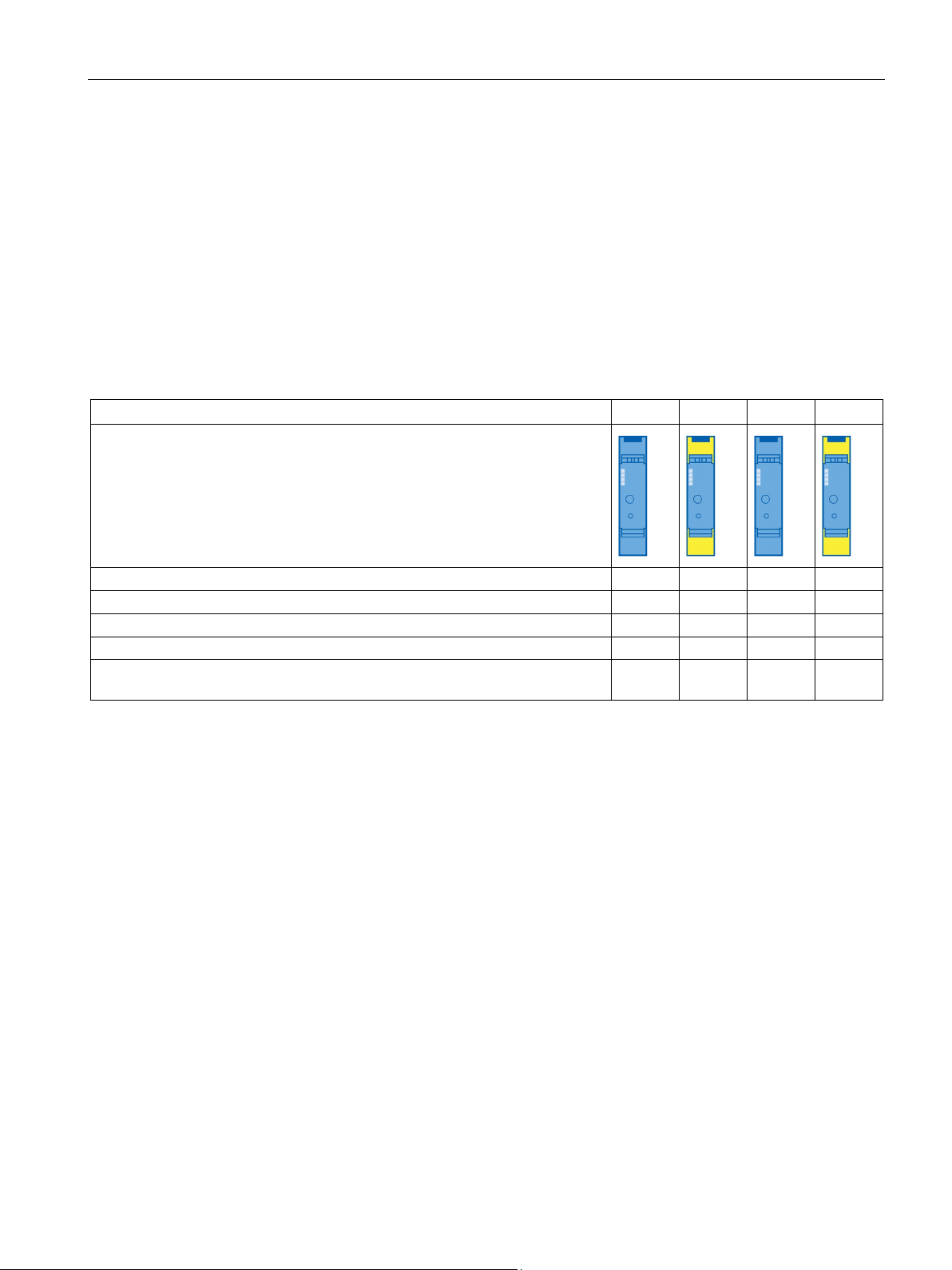
Feature
3RM10
3RM11
3RM12
3RM13
Direct-on-line starter
✓ ✓ -
-
Reversing starter
- - ✓
✓
ATEX certification overload protection
- ✓ -
✓
EN ISO 13849-1
Connection systems
3.4 Device versions
The 3RM1 motor starters are characterized by their compact design and narrow width.
They can be used for easy assembly of fuseless load feeders with SIRIUS motor starter
protectors. Alternatively, combinations with fuses or other short-circuit protection devices are
possible.
This allows implementation of load feeders with coordination type 1 for short-circuit currents
of up to 55 kA at 400 V.
The 3RM1 motor starters are available in four different versions:
Table 3- 1 Motor starter version
Product symbol
Overload protection with wide setting range ✓ ✓ ✓ ✓
Safety-related shutdown up to SILCL 3 to EN 62061, PL e/Cat. 4 to
- ✓ - ✓
The 3RM1 motor starters are optionally available with screw connections or push-in
connections.
Push-in connections are a form of spring-loaded terminals allowing fast wiring without tools
for rigid conductors or conductors equipped with end sleeves. For wiring finely-stranded or
stranded conductors without end sleeves on push-in connections, a screwdriver (with
3.0 x 0.5 mm blade) is required. A screwdriver (with 3.0 x 0.5 mm blade) is also required to
disconnect a conductor.
The advantages of the push-in terminals are found, as with all spring-loaded terminals, in
speed of assembly and disassembly and vibration-proof connection. There is no need for the
checking and tightening required with screw connections.
SIRIUS 3RM1 motor starter
Manual, 06/2016, A5E0345285095020A/RS-AE/005
29

Description
Current ranges
Versions
Adjustable response value current
[A]
Maximum permissible motor power
at 400 V AC [kW]
3RM1.01-.....
0.1 ... 0.5
0.12
3RM1.07-.....*
1.6 ... 7
3
* The versions of the 3RM1.07
heaters) up to a rated operational current of I
AC51
= 10 A.
Control supply voltages
Versions
Control supply voltage
3RM1...-.AA0.
24 V DC
3RM1...-.AA1.
110 … 230 V AC 50/60 Hz; 110 V DC
Note
Motor starters with 24 V DC control supply voltage
As is usual on solid
24
specifically shut down
disconnection of the control supply voltage. As a result, charging currents can arise briefly
upon activation of the control supply voltage. The buffering capacitance is decoupled by a
diode. Thi
You can find more information on the Internet
(
Note
3RM10/3RM12
with 24 V DC control supply voltage
The same voltage source (potential) must be used for the control supply voltage and the
control inputs.
The reference point for the control
3.4 Device versions
The 3RM1 motor starters are designed for the following rated operational currents of the
loads:
Table 3- 2 Current ranges
3RM1.02-..... 0.4 ... 2 0.75
-..... motor starter are also suitable for operating resistive loads (e.g.
The 3RM1 motor starters are designed for the following control supply voltages:
Table 3- 3 Control supply voltages
Note the following information for the different device versions:
-state motor starters, a buffering capacitance of 250 µF is installed in the
V DC control circuit of the 3RM1 Standard and Failsafe motor starters. Its purpose is to
the motor with the semiconductors in the event of failure or
s means that there is no influence on the dark test of safety-related outputs.
https://support.industry.siemens.com/cs/ww/en/view/91372998).
Standard motor starters
inputs is terminal A2.
SIRIUS 3RM1 motor starter
30 Manual, 06/2016, A5E0345285095020A/RS-AE/005
 Loading...