

Siemens Sirius Series, Sirius 3RA6 System Manual
COMPACT STARTER
sirius
System Manual · 02/2008
SIRIUS 3RA6 Compact Starter
SIRIUS Infeed System for 3RA6


SIRIUS industrial switchgear
Load feeders, motor and soft
starters
SIRIUS 3RA6 Compact Starter
System Manual
Introduction
Product-specific information
System description
Configuration
Communication via
AS-Interface
Description of the hardware
Functions
1
2
3
4
5
6
7
Installation/Removal
Connecting
Commissioning
Diagnostics
Accessories
Service
Technical data
8
9
10
11
12
13
14
02/2008
GWA 4NEB 560 0601-02 DS 02
Dimension drawings
Circuit diagrams
Appendix
15
16
A
Safety Guidelines
This manual contains notices you have to observe in order to ensure your personal safety, as well as to prevent
damage to property. The notices referring to your personal safety are highlighted in the manual by a safety alert
symbol, notices referring only to property damage have no safety alert symbol. These notices shown below are
graded according to the degree of danger.
DANGER
indicates that death or severe personal injury will result if proper precautions are not taken.
WARNING
indicates that death or severe personal injury may result if proper precautions are not taken.
CAUTION
with a safety alert symbol, indicates that minor personal injury can result if proper precautions are not taken.
CAUTION
without a safety alert symbol, indicates that property damage can result if proper precautions are not taken.
NOTICE
indicates that an unintended result or situation can occur if the corresponding information is not taken into
account.
If more than one degree of danger is present, the warning notice representing the highest degree of danger will
be used. A notice warning of injury to persons with a safety alert symbol may also include a warning relating to
property damage.
Qualified Personnel
The device/system may only be set up and used in conjunction with this documentation. Commissioning and
operation of a device/system may only be performed by qualified personnel. Within the context of the safety notes
in this documentation qualified persons are defined as persons who are authorized to commission, ground and
label devices, systems and circuits in accordance with established safety practices and standards.
Prescribed Usage
Note the following:
WARNING
This device may only be used for the applications described in the catalog or the technical description and only
in connection with devices or components from other manufacturers which have been approved or
recommended by Siemens. Correct, reliable operation of the product requires proper transport, storage,
positioning and assembly as well as careful operation and maintenance.
Trademarks
All names identified by ® are registered trademarks of the Siemens AG. The remaining trademarks in this
publication may be trademarks whose use by third parties for their own purposes could violate the rights of the
owner.
Disclaimer of Liability
We have reviewed the contents of this publication to ensure consistency with the hardware and software
described. Since variance cannot be precluded entirely, we cannot guarantee full consistency. However, the
information in this publication is reviewed regularly and any necessary corrections are included in subsequent
editions.
Siemens AG
Automation and Drives
Postfach 48 48
90327 NÜRNBERG
GERMANY
Ordernumber: 3RA6992-0A
Ⓟ 02/2008
Copyright © Siemens AG 2008.
Technical data subject to change

Table of contents
1 Introduction................................................................................................................................................ 9
2 Product-specific information
2.1 Standards/Regulations/Approvals ...............................................................................................11
2.2 Use as
3 System description .................................................................................................................................. 13
3.1 System overview..........................................................................................................................13
3.2 System configuration ...................................................................................................................15
3.2.1 System configuration without optional A
3.2.2 System configuration with optional AS-i mounting m
3.3 System components
4 Configuration .................................................................................................................
4.1 SIRIUS 3RA6 compact starter .....................................................................................................25
4.2 Supply possibilities in mai
4.2.1 SIRIUS infeed syst
4.2.2 3-phase busbar ............................................................................................................................34
4.2.3 8US busbar adapter
4.2.4 Infeed in accordance with UL 508 (T
5 Communication via AS
6 Description of the
6.1 SIRIUS 3RA61 compact starter direct s
presc
hardware..................................................................................................................... 41
..................................................................................................................... 11
ribed ........................................................................................................................12
S-i mounting
....................................................................................................................18
n circuit
em for 3RA6...................................................................................................28
............................................................................................................
-Interface ............................................................................................................. 39
................................................................................................28
ype E).................................................................................36
tarter..............................................................................41
module.....................................................16
odule..........................................................17
.......................... 25
.........35
6.2 SIRIUS 3RA62 compact starter reversing starter ........................................................................44
e
6.3 AS-i mounting module for compact start
7 Functions................................................................................................................................................. 49
y
7.1 Normal switching dut
7.2 Overload protection function
7.3 Short-circuit protection function ...................................................................................................56
7.4 Shutdown on malfunc
7.5 Disabling the ac
8 Installation/Removal ..........................................................................................................
8.1 Installing the SIRIUS 3RA6 compac
8.1.1 Mounting the compact starter on a DI
8.1.2 Installing the compact starter on a level surface (screw fastening).............................................60
8.1.3 Installing the
8.1.4 Installing the AS-i mounting module ............................................................................................63
SIRIUS 3RA6 Compact Starter
System Manual, 02/2008, GWA 4NEB 560 0601-02 DS 02
compact starter on a SIRIUS infeed system for 3RA6
..................................................................................................................49
........................................................................................................53
tion
.............................................................................................................57
tuator ..................................................................................................................58
r ..................................................................................47
...................... 59
t starter and AS-i mounting module ....................................59
N rail .................................................................................59
...........................................62
3

Table of contents
8.2 Removing the SIRIUS 3RA6 compact starter and AS-i mounting module ................................. 64
8.2.1 Removing the compact starter from a DIN rail............................................................................ 64
8.2.2 Remov
ing the compact starter from a level
8.2.3 Removing the compact starter from a SIRIUS infeed system for 3
8.2.4 Removing the AS-i mounting
module ......................................................................................... 68
surface (screw fastening)....................................... 65
RA6 ..................................... 66
9 Connecting .....................................................
9.1 General connection information ................................................................................................
......................................................................................... 69
.. 69
9.2 Connecting terminal blocks......................................................................................................... 73
9.3 Connecting the compact starter with
out optional AS-i
9.4 Connecting the compact starter (24 V) w
ith optional AS-i mounting module ............................. 77
mounting module ................................... 75
9.4.1 Connecting the AS-Interface....................................................................................................... 77
9.4.2 Connecting limit switches............................................................................................................ 78
9.5 Disconnecting terminal blocks..................................................................................................... 79
........................................................................................................................................ 81
10 Commissioni
ng
10.1 Settings on the compact starter .................................................................................................. 81
10.2 AS-Interface ................................................................................................................................ 82
10.2.1 Addressing via AS-Interface........................................................................................................ 82
ages.............................................................................................. 84
10.2.2 Process data and process i
11 Diagnostics ...................................................................................................................
m
........................... 85
11.1 Compact starter diagnostics........................................................................................................ 85
11.2 AS-i mounting module di
agnostics
.............................................................................................. 87
12 Accessories ............................................................................................................................................. 89
12.1 Control kit .................................................................................................................................... 89
12.1.1 Description of the hardware
...................................................................................................
..... 89
12.1.2 Using the control kit..................................................................................................................... 89
12.2 External auxiliary switch block .................................................................................................... 91
12.2.1 Description of the hardware
12.2.2 Installing and removing the auxiliary s
12.2.3 Connecting the auxiliary switch block for com
12.3 SIRIUS infeed syst
em for 3RA6.................................................................................................. 95
...................................................................................................
witch block for the compact starter ................................. 91
pact starter .......................................................... 93
12.3.1 Description of the hardware ...................................................................................................
12.3.2 Coding the SIRIUS infeed system for 3RA6
12.3.3 Installing the SIRIUS infeed syst
em for 3RA6 on a DIN rail ....................................................... 99
12.3.4 Installing the SIRIUS infeed system for 3RA6 on a le
12.3.5 Installing the accessories for a SIRIUS infeed system
12.3.6 Removing the accessories for a SIRIUS infeed system for 3RA6
............................................................................... 97
vel surface (screw fastening) ................ 103
for 3RA6.............................................. 104
............................................ 108
..... 91
..... 95
12.3.7 Removing the SIRIUS infeed system for 3RA6 from a DIN rail................................................ 109
Connecting the SIRIUS infeed system for 3RA6
12.3.8
...................................................................... 112
12.4 3-phase busbar ......................................................................................................................... 117
12.4.1 Description of the hardware
...................................................................................................
... 117
12.4.2 Connecting the 3-phase busbar................................................................................................ 120
12.5 8US busbar adapter
............................................................................................................
12.5.1 Description of the hardware ...................................................................................................
12.5.2 Installing the 8US busbar adapter plu
12.5.3 Removing the 8US busbar adapter plu
SIRIUS 3RA6 Compact Starter
s SIRIUS 3RA6 compact starter.................................... 122
s SIRIUS 3RA6 compact starter.................................. 126
...... 121
... 121
4 System Manual, 02/2008, GWA 4NEB 560 0601-02 DS 02

Table of contents
12.6 Terminal for Type E combination motor controller, UL 508 .......................................................127
12.6.1 Installing the terminal for a Type E self-protecte
12.6.2 Connecting the terminal for a Type E self-protected combination motor co
d combination motor controller (UL 508)........127
ntroller (UL
508)............................................................................................................................................128
m
12.7 Door-coupling rotary operating mechanis
12.7.1 Description of the hardware...................................................................................................
12.7.2 Installing the door-coupling rotary operating mechani
...............................................................................129
....129
sm ..........................................................129
12.7.3 Commissioning the door-coupling rotary operating mechanism................................................130
13 S
ervice................................................................................................................................................... 133
13.1 Installing/Removing main conduc
tor terminal bloc
13.2 Installing/Removing auxiliary and control conductor terminal blocks
13.3 Malfunction (e.g. end of service lif
13.4 Replacing the SIRIUS 3RA6 c
e reached)............................................................................137
ompact starter............................................................................138
ks.................................................................133
........................................135
13.5 Order numbers...........................................................................................................................140
t
13.5.1 Order numbers for the SIRIUS 3RA6 compac
13.5.2 Order numbers for acce
ssories..................................................................................................141
14 Technical data ................................................................................................................
starter...............................................................140
....................... 145
14.1 SIRIUS 3RA6 compact starter ...................................................................................................145
14.2 AS-i mounting module
14.3 SIRIUS infeed syst
15 Dimension drawing
s .............................................................................................................................. 161
..........................................................................................................
em for 3RA6.................................................................................................156
15.1 SIRIUS 3RA6 compact starter ...................................................................................................161
15.1.1 Dimensions (in mm) ...................................................................................................................161
15.1.2 Minimum distances from neighboring components (dimensions in mm)
15.2
SIRIUS infeed syst
em for 3RA6.................................................................................................164
...................................163
15.2.1 Dimensions (in mm) ...................................................................................................................164
15.2.2 Minimum distances from neighboring components (dimensions in mm)
...................................168
......155
16 Circ
uit diagram
s..................................................................................................................................... 169
16.1 Main circuit of 3RA6 compact starter .........................................................................................169
t
16.2 Control circuit for 3RA6 compac
starter....................................................................................171
A Appendix................................................................................................................................................ 173
A.1 References.................................................................................................................................173
A.2 List of abbreviations
.........................................................................................................
..........174
Glossary ................................................................................................................................................ 175
Index...................................................................................................................................................... 177
SIRIUS 3RA6 Compact Starter
System Manual, 02/2008, GWA 4NEB 560 0601-02 DS 02
5

Table of contents
Tables
Table 1-1
Table 1-2 Symbols....................................................................................................................................... 10
Table 3-1 Compact starter communication options..................................................................................... 13
Table 3-2 Accessories for the 3RA6 compact starter.................................................................................. 14
Table 3-3 Control circuit (configuration) ...................................................................................................... 15
Table 4-1 Maximum rated current (3RA6 compact starter)......................................................................... 26
Table 4-2 Maximum rated current (infeed system for 3RA6)...................................................................... 28
Table 4-3 Short-circuit protection for SIRIUS infeed system for 3RA6 ....................................................... 31
Table 4-4 Short-circuit protection for terminal block (3RV1917-5D) ........................................................... 32
Table 4-5 Sub-functions of motor feeders according to UL 508 and CSA 22.2.......................................... 36
Table 4-6 Categorization of motor feeders in accordance with UL 508...................................................... 36
Table 7-1 Actuator display elements OFF (direct starter)........................................................................ 49
Table 7-2 Actuator display elements OFF (reversing starter).................................................................. 50
Table 7-3 Actuator display elements READY (direct starter) .................................................................. 50
Table 7-4 Actuator display elements READY (reversing starter) ............................................................ 51
Table 7-5 Actuator TRIPPED display elements (direct/reversing starter)................................................... 51
Table 7-6 Overload trip display elements (direct starter/reversing starter)................................................. 53
Chapter overview .......................................................................................................................... 9
Table 7-7 Short circuit trip display elements (direct starter/reversing starter)............................................. 56
Table 7-8 Malfunction display elements (direct starter/reversing starter) ................................................... 57
Table 9-1 Conductor cross-sections of main conductor terminals .............................................................. 71
Table 9-2 Conductor cross-sections of auxiliary conductor terminals......................................................... 72
Table 9-3 Pin assignments for 3RA61 compact starter direct starter ......................................................... 75
Table 9-4 Pin assignments for 3RA62 compact starter reversing starter ................................................... 76
Table 9-5 Limit switch terminal.................................................................................................................... 78
Table 9-6 Conductor cross-sections of limit switch terminal ....................................................................... 78
Table 10-1 AS-i profile (AS-i mounting module)............................................................................................ 82
Table 10-2 Logical assignment ..................................................................................................................... 84
Table 11-1 Display concept of the 3RA61 compact starter direct starter...................................................... 85
Table 11-2 Display concept of the 3RA62 compact starter reversing starter................................................ 86
Table 11-3 Display concept of the "AS-i/FAULT" LED.................................................................................. 87
Table 11-4 Display concept of the "AUX PWR" LED .................................................................................... 87
Table 12-1 Pin assignments on the auxiliary switch block for compact starter............................................. 93
Table 12-2 Conductor cross-section of the terminals on the auxiliary switch block for compact starter ...... 94
Table 12-3 Short designations for the infeed system for 3RA6 .................................................................... 95
Table 12-4 Stripping lengths (infeed system for 3RA6) .............................................................................. 112
SIRIUS 3RA6 Compact Starter
6 System Manual, 02/2008, GWA 4NEB 560 0601-02 DS 02

Table of contents
Table 12-5 Screw-type infeed (25/35 mm²) (L1, L2, L3) and PE infeed, 25/35 mm², with screw-type
connection technology ...............................................................................................................114
Table 12-6 Screw-type infeed (50/70 mm²) (L1, L2, L3)..............................................................................114
Table 12-7 Spring-loaded infeed (L1, L2, L3) and PE infeed, 25/35 mm², with spring-loaded
connection technology ...............................................................................................................115
Table 12-8 Screw-type infeed (25/35 mm²) (T1, T2, T3), screw-type infeed (50/70 mm²) (T1, T2, T3),
2-slot/3-slot extension modules (T1, T2, T3) and PE tap, 6/10 mm
connection technology ...............................................................................................................115
Table 12-9 PE tap, 6/10 mm2, with spring-loaded connection technology ..................................................116
Table 12-10 Terminal block............................................................................................................................116
Table 12-11 3-phase infeed terminal .............................................................................................................120
Table 12-12 Bus bar system ..........................................................................................................................121
Table 12-13 Conductor cross-sections of the terminal for a self-protected combination motor controller
(Type E) to UL 508.....................................................................................................................128
2
, with screw-type
Figures
Figure 3-1
Figure 3-2 SIRIUS 3RA6 compact starter without AS-i mounting module (system configuration) ...............16
Figure 3-3 SIRIUS 3RA6 compact starter with AS-i mounting module (system configuration) ....................17
Figure 4-1 Distance of compact starter from neighboring components (dimensions in mm)........................27
Figure 4-2 Multi-tier configuration of the infeed system for 3RA6.................................................................30
Figure 4-3 Distance of infeed system for 3RA6 from neighboring components (dimensions in mm)...........31
Integration into the automation environment ...............................................................................15
Figure 4-4 Combination with other sizes (SIRIUS infeed system for 3RA6).................................................33
Figure 4-5 Combination with other sizes (3-phase busbar) ..........................................................................34
Figure 4-6 Infeed via 8US busbar adapter ....................................................................................................35
Figure 4-7 Terminals for infeed in accordance with UL 508 (Type E)...........................................................37
Figure 7-1 Manual/auto reset following an overload trip ...............................................................................54
Figure 8-1 Installing a 3RA62 compact starter on a level surface (screw fastening)....................................61
Figure 9-1 Representation of stripping lengths on terminals.........................................................................69
Figure 9-2 Test probe openings on the 3RA6 compact starter .....................................................................70
Figure 9-3 Contact with cables......................................................................................................................77
Figure 12-1 Infeed system for 3RA6 ...............................................................................................................96
Figure 12-2 Locking the SIRIUS infeed system for 3RA6 for compact starters..............................................97
Figure 12-3 Coding the SIRIUS infeed system for 3RA6................................................................................98
Figure 12-4 Installation scenarios involving the spring-loaded infeed ............................................................99
Figure 12-5 Mounting options for PE infeed and PE tap...............................................................................104
Figure 12-6 Test probe openings on the infeed system................................................................................113
SIRIUS 3RA6 Compact Starter
System Manual, 02/2008, GWA 4NEB 560 0601-02 DS 02
7

Table of contents
Figure 12-7 Configuration involving 3-phase busbar.................................................................................... 118
Figure 12-8 Configuration involving 3-phase busbar to UL 508 (Type E) .................................................... 119
Figure 12-9 Installing the door-coupling rotary operating mechanism ......................................................... 129
Figure 12-10 Door-coupling rotary operating mechanism; operating information.......................................... 131
Figure 12-11 Door-coupling rotary operating mechanism, securing .............................................................. 132
Figure 13-1 Coding of auxiliary and control conductor terminals ................................................................. 135
Figure 13-2 Replacing the compact starter .................................................................................................. 138
Figure 15-1 Side view of the 3RA6 compact starter (screw-type connection technology)........................... 161
Figure 15-2 Side view of the 3RA6 compact starter (spring-loaded connection technology) ...................... 162
Figure 15-3 Dimension drawing of screw-type infeed (50/70 mm2) featuring outgoing terminals with
screw-type connection technology............................................................................................ 164
Figure 15-4 Dimension drawing of screw-type infeed (25/35 mm2) featuring outgoing terminals with
screw-type connection technology............................................................................................ 164
Figure 15-5 Dimension drawing of screw-type infeed (50/70 mm2) featuring outgoing terminals with
spring-loaded connection technology ....................................................................................... 165
Figure 15-6 Dimension drawing of screw-type infeed (25/35 mm2) featuring outgoing terminals with
spring-loaded connection technology ....................................................................................... 165
Figure 15-7 Dimension drawing of spring-loaded infeed.............................................................................. 166
Figure 15-8 Dimension drawing of extension blocks featuring outgoing terminals with spring-loaded
connection technology .............................................................................................................. 166
Figure 15-9 Dimension drawing of extension blocks featuring outgoing terminals with screw-type
connection technology .............................................................................................................. 167
Figure 15-10 Distances from neighboring components (infeed system for 3RA6) ........................................ 168
Figure 16-1 Main circuit of 3RA61 compact starter direct starter................................................................. 169
Figure 16-2 Main circuit of 3RA62 compact starter reversing starter........................................................... 170
Figure 16-3 Control circuit of 3RA61 compact starter direct starter ............................................................. 171
Figure 16-4 Control circuit of 3RA62 compact starter reversing starter ....................................................... 172
SIRIUS 3RA6 Compact Starter
8 System Manual, 02/2008, GWA 4NEB 560 0601-02 DS 02

Introduction
Purpose of this manual
This SIRIUS 3RA6 Compact Starter Manual describes the compact starter and its functions.
It contains information about configuration, commissioning and servicing.
As well as providing information about the compact starter itself, the manual also deals with
compatible infeed systems. These are the SIRIUS infeed system for 3RA6, the
insulated 3RV19 three-phase busbar system and the 8US busbar adapter. The options in
terms of connecting to circuit breakers of other sizes and to the 3RV19 infeed system are
also discussed within this context.
Furthermore, to facilitate configuration the manual contains dimension drawings and
technical data of the system components.
Topics
The manual consists of instructive chapters, which are intended for reference purposes. The
following table provides an overview of the topics covered:
Table 1-1 Chapter overview
Chapter Contents
Introduction Provides an overview of the manual's contents
Product-specific information Provides product-specific information about the compact starter
System description Provides an overview of the system components and their
Configuration Provides information (e.g. environmental requirements, use in
Communication via
AS-Interface
Description of the hardware Describes the compact starter's display elements and operator
Functions Describes the compact starter's functions
Installation/Removal Describes how to install and remove the compact starter
Connection Describes how to connect the compact starter
Commissioning Provides information about the possible settings on the compact
Diagnostics Provides information about what defined display element states
1
integration into the automation environment
combination with other products, etc.) about using the compact
starter and accessories, which need to be taken into account right
from the configuration stage
Provides information about communication based on an
AS-Interface
controls
starter and addressing of the AS-i mounting module
signal in terms of device states and describes diagnostics via the
AS-Interface
SIRIUS 3RA6 Compact Starter
System Manual, 02/2008, GWA 4NEB 560 0601-02 DS 02
9
Introduction
Chapter Contents
Accessories Provides information about accessories (control kit, auxiliary switch
block for compact starter, infeed system for 3RA6, 3-phase busbar,
8US busbar adapter, type E terminal, door-coupling rotary operating
mechanism). This information includes a description of the hardware
as well as the installation/removal and connection processes.
Service Provides information about servicing or maintenance activities. This
includes exchanging the entire compact starter or the individual
terminal blocks. This chapter also explains the order number system
used for the compact starter.
Technical data Provides technical data for the compact starter and its accessories
Dimension drawings Provides dimension drawings for the compact starter and its
accessories
Circuit diagrams Provides circuit diagrams for the compact starter
Required basic knowledge
To understand this manual, you will need to have a general knowledge of low-voltage
controls and distribution and also of automation.
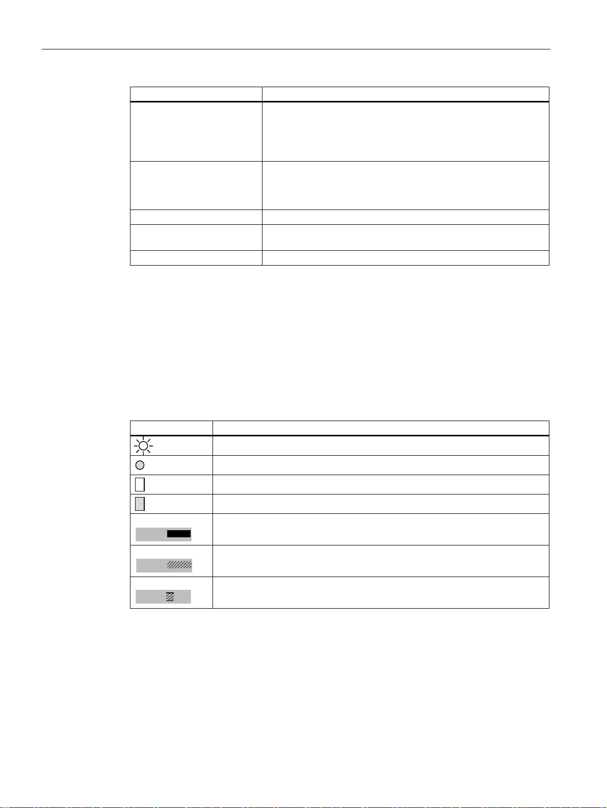
Symbols used in the text
The following table explains the meaning of the various symbols used within this document:
Table 1-2 Symbols
Symbol Meaning
LED is illuminated
LED not illuminated
Mechanical display is white
No mechanical display
Solid and stranded conductors
Finely stranded conductor without end sleeve
Finely stranded conductor with end sleeve
SIRIUS 3RA6 Compact Starter
10 System Manual, 02/2008, GWA 4NEB 560 0601-02 DS 02

Product-specific information
2.1 Standards/Regulations/Approvals
Standards
The 3RA6 compact starter conforms to the following standards:
● IEC / EN 60947-6-2
● UL 508 Type E
● CSA C22.2 No. 14 Type E
Approvals/Test reports
UL and CSA approval was being sought at the time of going to press. Once approval has
been obtained, the compact starter will be marked with the symbols
Note
- Marking
2
and .
Any compact starter that does not bear the
Confirmation of approvals, test certificates and characteristic curves is available via the
Internet:
www.siemens.de/lowvoltage/technical-assistance
Compact starter degree of protection
The compact starter's degree of protection is IP20. In the terminal area it features
IP00 degree of protection.
Infeed system degree of protection for 3RA6
The infeed system for the 3RA6 features IP20 degree of protection. In the terminal area it
features IP00 degree of protection.
Isolating features
The requirements of IEC / EN 60947-3 have been met in respect of the isolating features.
marking is not intended for the US market.
SIRIUS 3RA6 Compact Starter
System Manual, 02/2008, GWA 4NEB 560 0601-02 DS 02
11

Product-specific information
2.2 Use as prescribed
Main switch and EMERGENCY STOP/EMERGENCY OFF function
The main switch and EMERGENCY STOP/EMERGENCY OFF meet the requirements of
IEC / EN 60204-1.
Characteristic curves
If required, you can request the characteristic curves for all setting ranges by sending an email to our Technical Assistance team: technical-assistance@siemens.com. Alternatively,
you can get them by visiting the following website:
www.siemens.de/lowvoltage/technical-assistance
2.2 Use as prescribed
Compact starter
Prescribed use in accordance with IEC / EN 60947-6-2.
SIRIUS 3RA6 Compact Starter
12 System Manual, 02/2008, GWA 4NEB 560 0601-02 DS 02

System description
3.1 System overview
General
The SIRIUS 3RA6 compact starter is a universal motor feeder that meets the requirements
of IEC / EN 60947-6-2 (weld-free). It combines the functions of a circuit breaker, a solid-state
overload relay and a contactor within a single housing and can be used in any application
involving the direct starting of standard induction motors with a rating of up to 32 A
(approx. 15 kW/400 V).
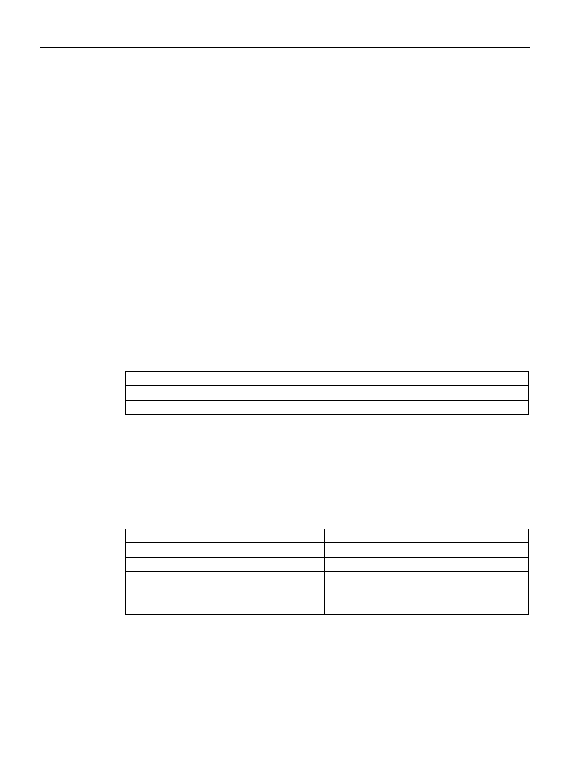
The compact starter is available as either a direct or a reversing starter.
As an option, an AS-i mounting module can be mounted on the compact starter with a 24 V
control voltage. The AS-i mounting module enables the compact starter to communicate via
an AS-Interface.
Table 3-1 Compact starter communication options
Compact starter Communication
Compact starter without optional AS-i mounting module No communication
Compact starter (24 V) with optional AS-i mounting
module
3
Communication via AS-Interface
Setting ranges
The compact starter is available with five different current setting ranges and three different
control voltage ranges. For details of the corresponding compact starter order numbers,
please refer to "
● Current setting ranges:
0.1 to 0.4 A
0.32 to 1.25 A
1 to 4 A
3 to 12 A
8 to 32 A
● Control voltage ranges (AC/DC):
24 V
42 to 70 V
110 to 240 V
SIRIUS 3RA6 Compact Starter
System Manual, 02/2008, GWA 4NEB 560 0601-02 DS 02
Order numbers for the SIRIUS 3RA6 comp
act starter (Page 140) ".
13

System description
3.1 System overview
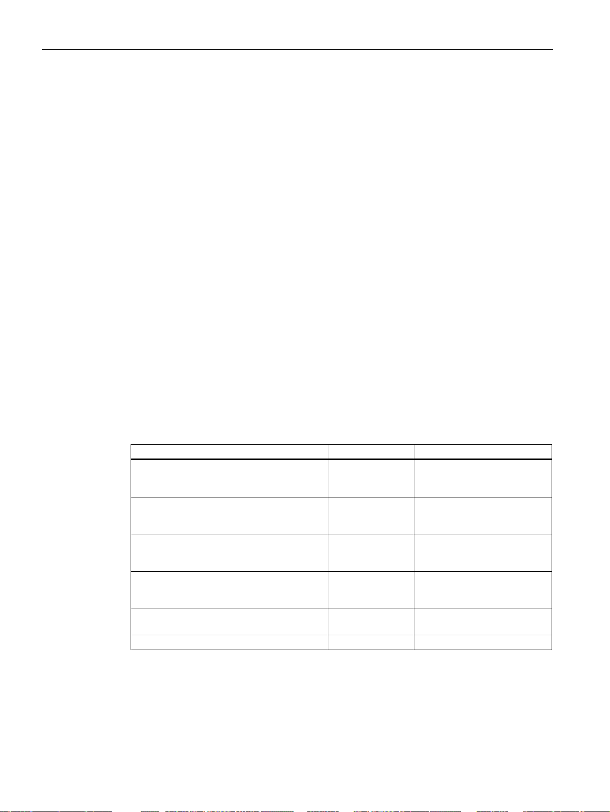
Accessories
As well as providing details of the compact starter and AS-i mounting module, this document
also describes the following accessories:
Table 3-2 Accessories for the 3RA6 compact starter
Accessories Description Chapter
Auxiliary switch block for
compact starter
Control kit Tool for closing the main
Adapter for screw fastening the
compact starter
Terminals for
"Combination Controller Type E"
Infeed system for 3RA6 The infeed system for 3RA6 is a
3-phase busbar The 3-phase busbar enables
8US busbar adapter The 8US busbar adapter
Door-coupling rotary operating
mechanism
Optional auxiliary switch block in
the following versions: 2 NO
contacts, 2 NC contacts or
1 NO contact + 1 NC contact
contacts manually by means of
the actuator
The adapters for screw
fastening enable you to install
the compact starter on a level
surface (screw fastening).
The terminals conform to the
creepages and clearances
stipulated by UL 508 (Type E).
modular infeed system with an
optional PE system. The
permanent wiring means that
compact starters can be
mounted quickly and easily.
several compact starters to be
fed using a single infeed
terminal.
enables the compact starter to
be mechanically fastened and
electrically connected to a
busbar system.
Door-coupling rotary operating
mechanisms enable compact
starters to be operated with the
control cabinet doors closed.
External auxiliary switch block
(Page 91)
Control kit (Page 89)
Installing the compact starter on
a level surface (screw fastening)
(Page 60)
Terminal for Type E
combination motor controller,
UL 508 (Page 127)
SIRIUS infeed system for 3RA6
(Page 95)
3-phase busbar (Page 117)
8US busbar adapter
(Page 121)
Door-coupling rotary operating
mechanism (Page 129)
SIRIUS 3RA6 Compact Starter
14 System Manual, 02/2008, GWA 4NEB 560 0601-02 DS 02
System description
$6,QWHUIDFH
352),%86352),QHW
3.2 System configuration
3.2 System configuration
Main circuit
The following supply options are available for the compact starter's main circuit:
● Parallel wiring
● Infeed system for 3RA6
(For additional information, please refer to "
SIRIUS infeed system for 3RA6 (Page 95)".)
● 3-phase busb
(For additional information, please refer to "
● 8US busbar
(For additional information, please refer to "
ar
3-phase busbar (Page 117)".)
adapter
8US busbar adapter (Page 121)".)
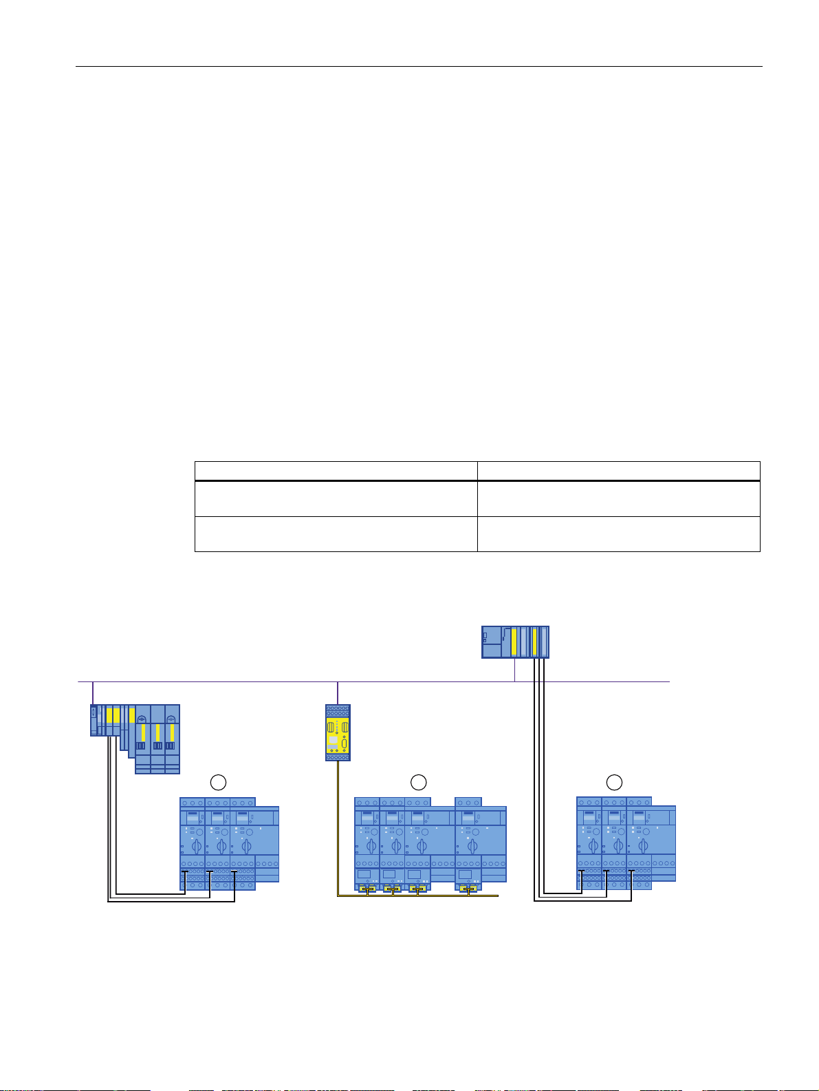
Control circuit
The control circuit can be structured as follows:
Table 3-3 Control circuit (configuration)
Compact starter Control system
Compact starter without optional AS-i mounting
module
Compact starter (24 V) with optional
AS-i mounting module
Parallel wiring to control system (e.g. PLC)
AS-Interface
Examples of how the compact starter can be integrated into the automation environment
6
)
(76
3%31
$6 L /LQN
Figure 3-1 Integration into the automation environment
(1) 3RA6 compact starter without AS-i mounting module
(2) 3RA6 compact starter with AS-i mounting module
SIRIUS 3RA6 Compact Starter
System Manual, 02/2008, GWA 4NEB 560 0601-02 DS 02
$6,QWHUIDFH
15
System description
3.2 System configuration
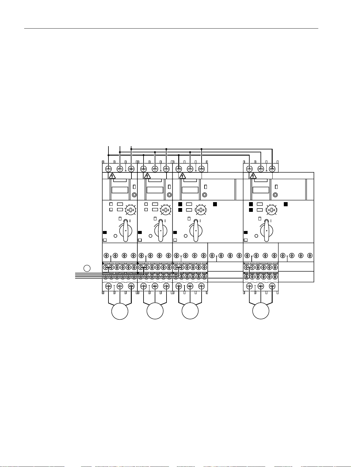
3.2.1 System configuration without optional AS-i mounting module
Configuration
The compact starter is connected to the control system via parallel wiring. Control takes
place via the following terminals:
● Direct starter: A1+, A2-
● Reversing starter: A1+, A2/B2-, B1+
View
WARNING
SIRIUS
0
RNING
SIRIUS
0
WARNINGWA
SIRIUS
0
WARNIN G
SIRIUS
0
Figure 3-2 SIRIUS 3RA6 compact starter without AS-i mounting module (system configuration)
(1) Connection to control system (e.g. PLC)
SIRIUS 3RA6 Compact Starter
16 System Manual, 02/2008, GWA 4NEB 560 0601-02 DS 02
System description
$ ; 3:5
$8; 3:5
3.2 System configuration
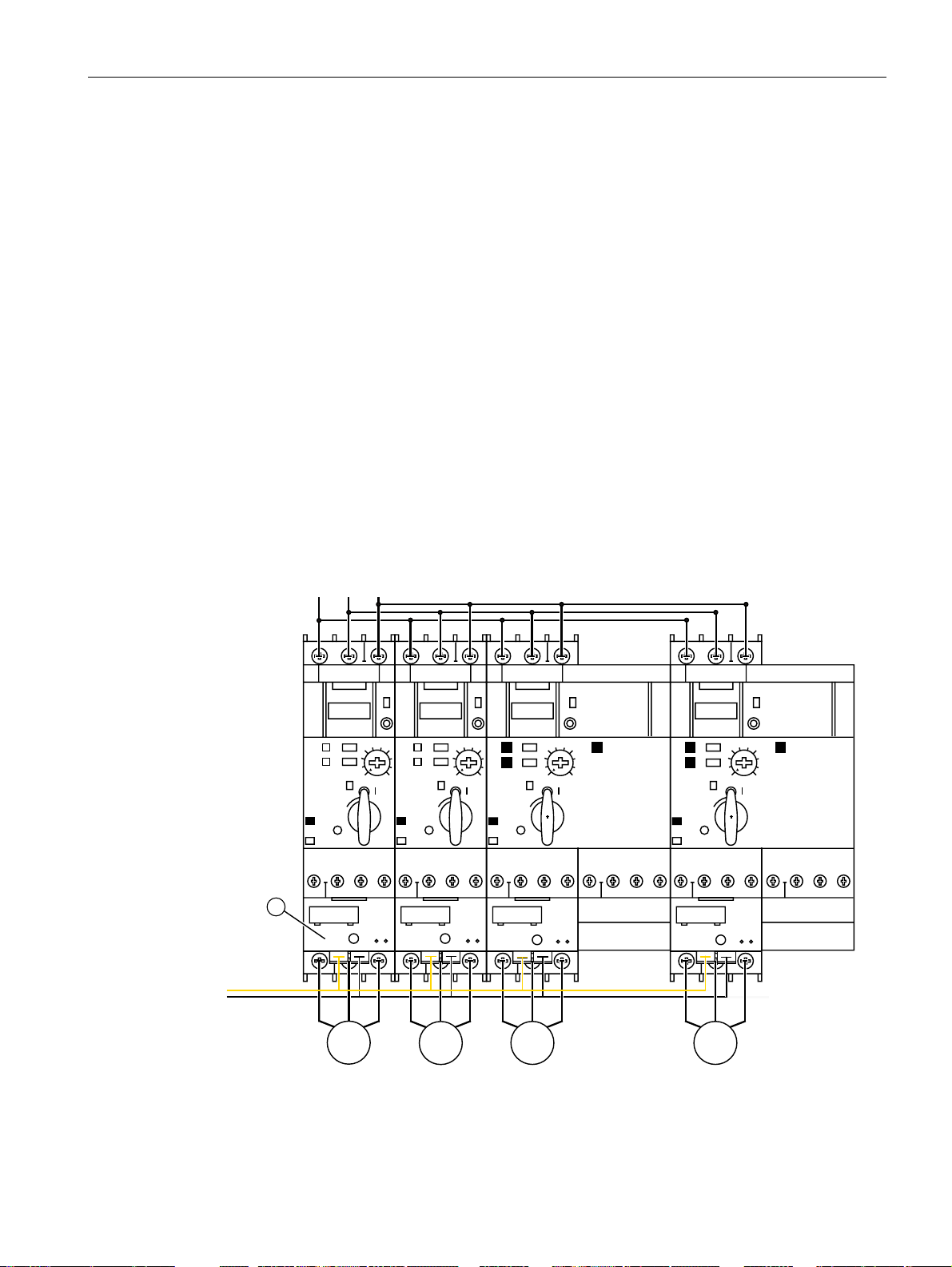
3.2.2 System configuration with optional AS-i mounting module
The compact starter with 24 V control voltage can be controlled via an AS-Interface. The
actuator sensor interface (AS-Interface) is a modular networking system for sensors and
actuators at the lowest field level.
Configuration
If the AS-Interface is being used for control purposes, the AS-i mounting module needs to be
installed on the compact starter (24 V) instead of the two auxiliary circuit terminals. The AS-i
and auxiliary voltage cables are connected to the AS-i mounting module.
An AS-i power supply is used to feed the AS-i voltage into the AS-i cable, which also serves
as a communication cable between the AS-i master and slave. The auxiliary voltage is
supplied by a 24 VDC PELV power supply in accordance with VDE 0106 safety class III.
For additional information on the AS-Interface, please refer to the manual entitled
"AS-Interface System"
(order number: 3RK2703-3AB02-1AA1).
For additional information on connecting the AS-i mounting module, please refer
Connecting the compact starter (24 V) with optional AS-i mounting modul
to "
e (Page 77) ".
View
SIRIUS SIRIUSSIRIUS SIRIUS
$
$6 L
0
Figure 3-3 SIRIUS 3RA6 compact starter with AS-i mounting module (system configuration)
(1) AS-i mounting module
SIRIUS 3RA6 Compact Starter
System Manual, 02/2008, GWA 4NEB 560 0601-02 DS 02
0
00
17

System description
3.3 System components
3.3 System components
SIRIUS 3RA6 compact starter
System component Order number Image
3RA61 compact starter
direct starter
3RA61
3RA62 compact starter
reversing starter
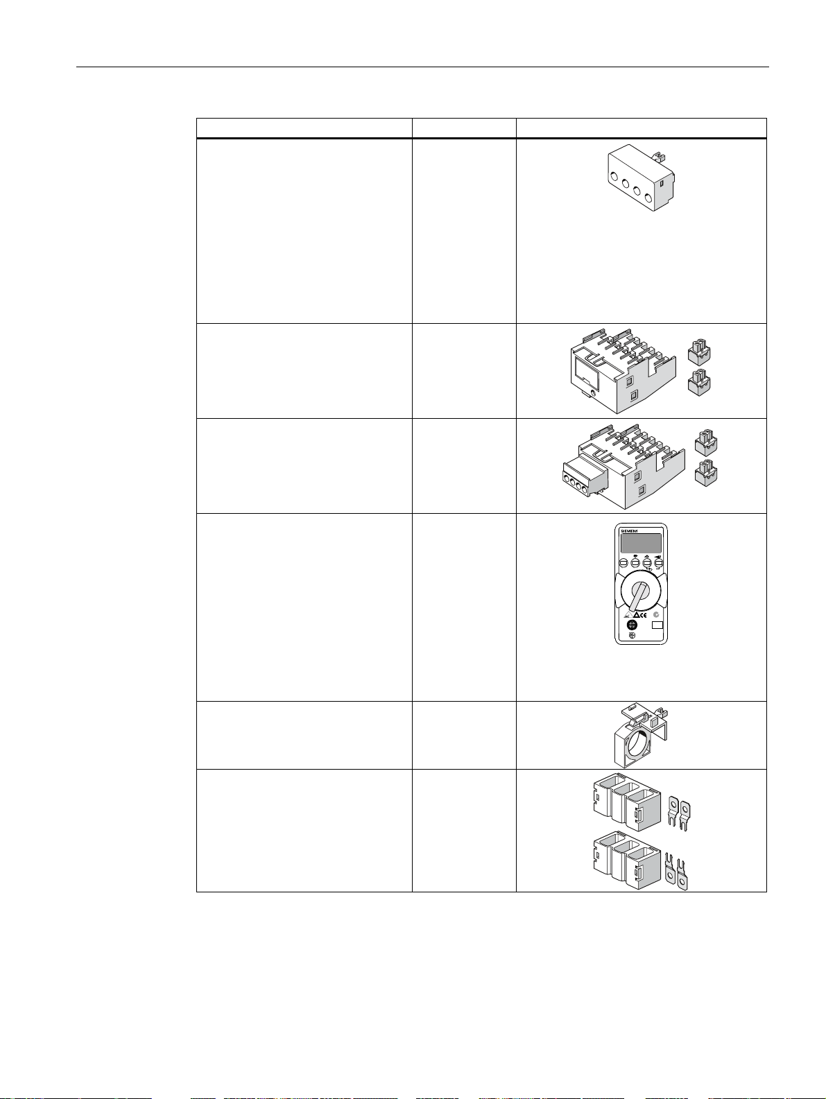
Main conductor terminal
(2 terminals/package for incoming
and outgoing terminals)
- Screw-type connection technology
- Spring-loaded connection
technology
Terminal for self-protected
combination motor controller
(Type E) to UL 508
3RA62
3RA6920-1A
3RA6920-2A
3RV1928-1H
SIRIUS 3RA6 Compact Starter
18 System Manual, 02/2008, GWA 4NEB 560 0601-02 DS 02
System description
3.3 System components
System component Order number Image
Auxiliary switch block for
compact starter
- Screw-type connection technology:
2 NO contacts
2 NC contacts
1 NO contact + 1 NC contact
- Spring-loaded connection
technology:
2 NO contacts
2 NC contacts
1 NO contact + 1 NC contact
AS-i mounting module for compact
starter
3RA6911-1A
3RA6912-1A
3RA6913-1A
3RA6911-2A
3RA6912-2A
3RA6913-2A
3RA6970-3A
AS-i mounting module for compact
3RA6970-3B
starter with two local inputs for safe
shutdown
AS-i mounting module addressing
3RK1904-2AB01
unit
- For active AS-Interface modules,
intelligent sensors and final
controlling elements
- Corresponds to AS-Interface
version 2.1
- Includes extended addressing
mode
- Scope of delivery includes
addressing cable (1.5 m stereo
jack)
Control kit 3RA6950-0A
Adapter for screw fastening the
3RA6940-0A
compact starter
(you will need 2 sets for the
reversing starter)
3RK1904-2AB01
ESC
DT
ADDR
DDR
+
Proile
MEM
Data
ASIV
Par m te
OFF
Memo y
COM
N 17
4321b
5
1
ASI +
3
ASI –
24
IRAd es i g
1
SIRIUS 3RA6 Compact Starter
System Manual, 02/2008, GWA 4NEB 560 0601-02 DS 02
19
System description
3.3 System components
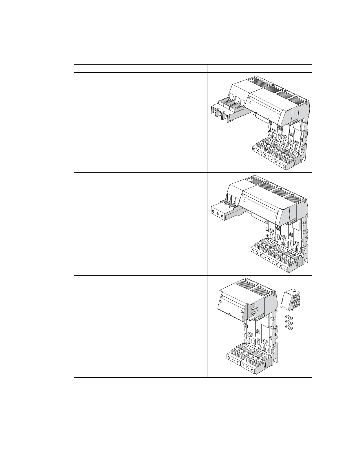
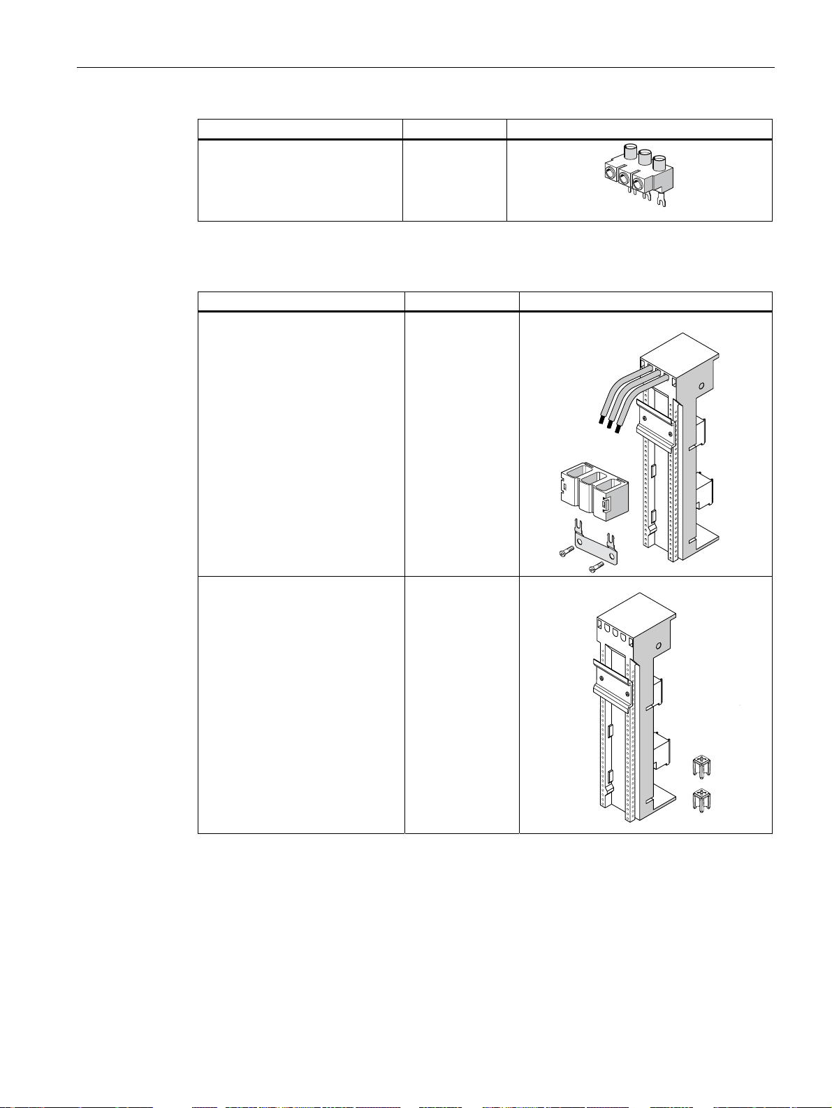
SIRIUS infeed system for 3RA6
System component Order number Image
Left infeed, 50/70 mm²
screw terminal with three slots,
outgoing terminals with
- Screw-type connection technology
- Spring-loaded connection
technology
Incl. PE bar
(for installing Type E starters in
accordance with UL 508)
3RA6813-8AB
3RA6813-8AC
Left infeed, 25/35 mm²
screw terminal with three slots,
outgoing terminals with
- Screw-type connection technology
- Spring-loaded connection
technology
Incl. PE bar
Extension module with two slots,
outgoing terminals with
- Screw-type connection technology
- Spring-loaded connection
technology
Incl. PE bar
3RA6812-8AB
3RA6812-8AC
3RA6822-0AB
3RA6822-0AC
SIRIUS 3RA6 Compact Starter
20 System Manual, 02/2008, GWA 4NEB 560 0601-02 DS 02
System description
3.3 System components
System component Order number Image
Extension module with three slots,
outgoing terminals with
- Screw-type connection technology
- Spring-loaded connection
technology
Incl. PE bar
3RA6823-0AB
3RA6823-0AC
Left or right infeed, 25/35 mm²,
with spring-loaded connection
technology
PE infeed, 25/35 mm², with
- Screw-type connection technology
- Spring-loaded connection
technology
PE tap, 6/10 mm², with
- Screw-type connection technology
- Spring-loaded connection
technology
PE extension connector 3RA6890-0EA
Terminal block 3RV1917-5D
3RA6830-5AC
3RA6860-6AB
3RA6860-5AC
3RA6870-4AB
3RA6870-3AC
SIRIUS 3RA6 Compact Starter
System Manual, 02/2008, GWA 4NEB 560 0601-02 DS 02
21
System description
3.3 System components
System component Order number Image
45 mm adapter for infeed system for
3RA6
(for mounting size S0 circuit breakers
(max. 12.5 A / 400 V; I
the infeed system for 3RA6)
< 53 kA) on
CU
3RA6890-0BA
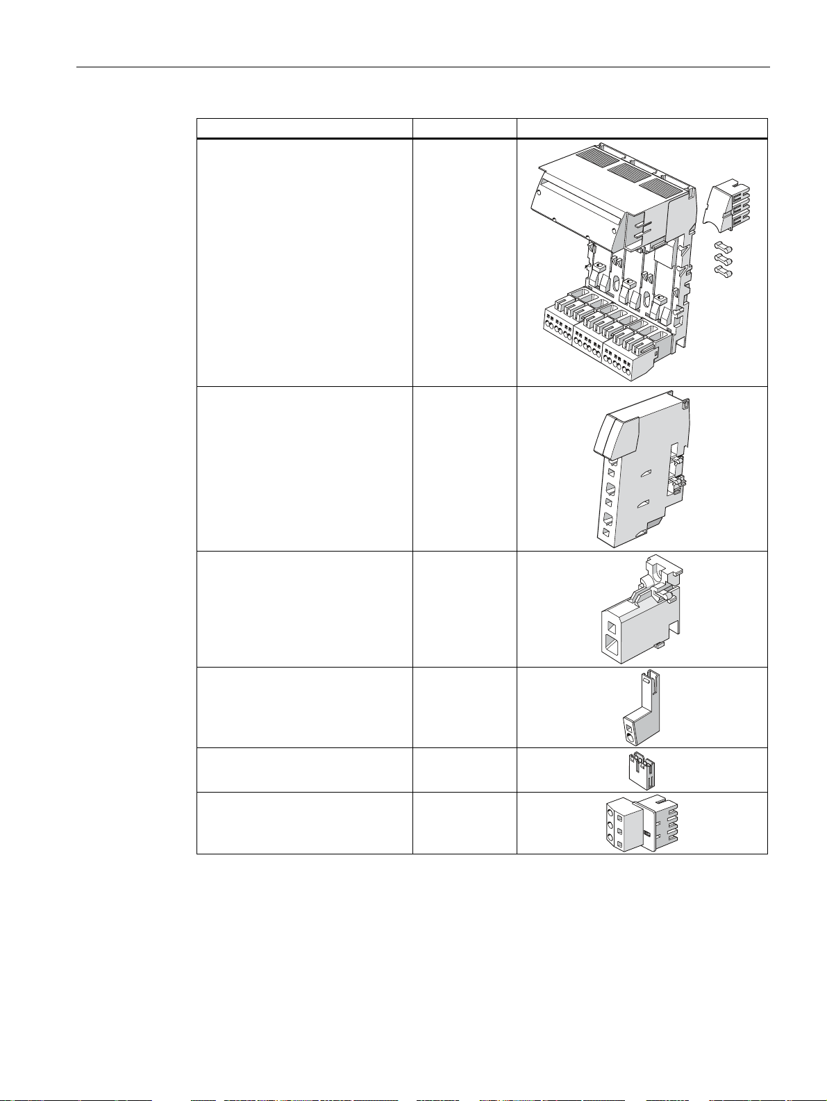
3-phase busbar
Extension connector for 3RV19
(connects SIRIUS infeed system for
3RA6 to 3RV19 infeed system)
Extension connector
(for reordering an original part that
has been lost)
System component Order number Image
3-phase busbar
- 2 partitions
- 3 partitions
- 4 partitions
- 5 partitions
3-phase infeed terminal,
connection from the bottom, with
screw-type connection technology
3RA6890-1AA
3RA6890-1AB
3RV1915-1AB
3RV1915-1BB
3RV1915-1CB
3RV1915-1DB
3RV1915-5B
Connection piece
for connecting compact starters to
size S00
circuit breakers
Cover cap for terminal lugs 3RV1915-6AB
3-phase infeed terminal,
connection from the top, with
screw-type connection technology
SIRIUS 3RA6 Compact Starter
3RV1915-5DB
3RV1925-5AB
22 System Manual, 02/2008, GWA 4NEB 560 0601-02 DS 02
System description
3.3 System components
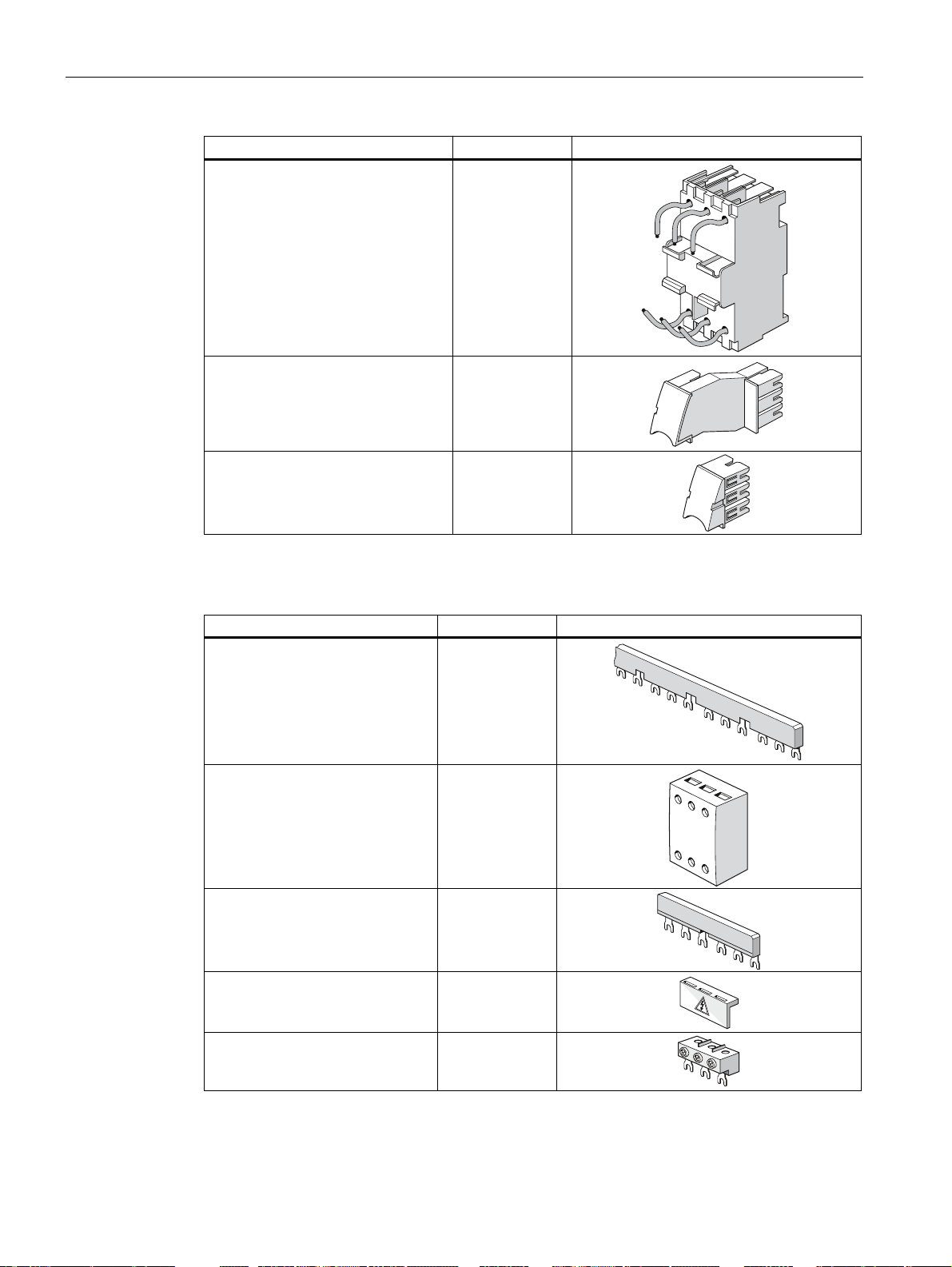
System component Order number Image
3-phase infeed terminal
for installing Type E starters,
UL 508
with screw-type connection
technology
3RV1925-5EB
8US busbar adapter
System component Order number Image
Busbar adapter
for 60 mm system
8US1211-1NS10
Device holder for side mounting on
busbar adapter
(only if installing a
3RA62 reversing starter)
8US1250-1AA10
SIRIUS 3RA6 Compact Starter
System Manual, 02/2008, GWA 4NEB 560 0601-02 DS 02
23
System description
3.3 System components
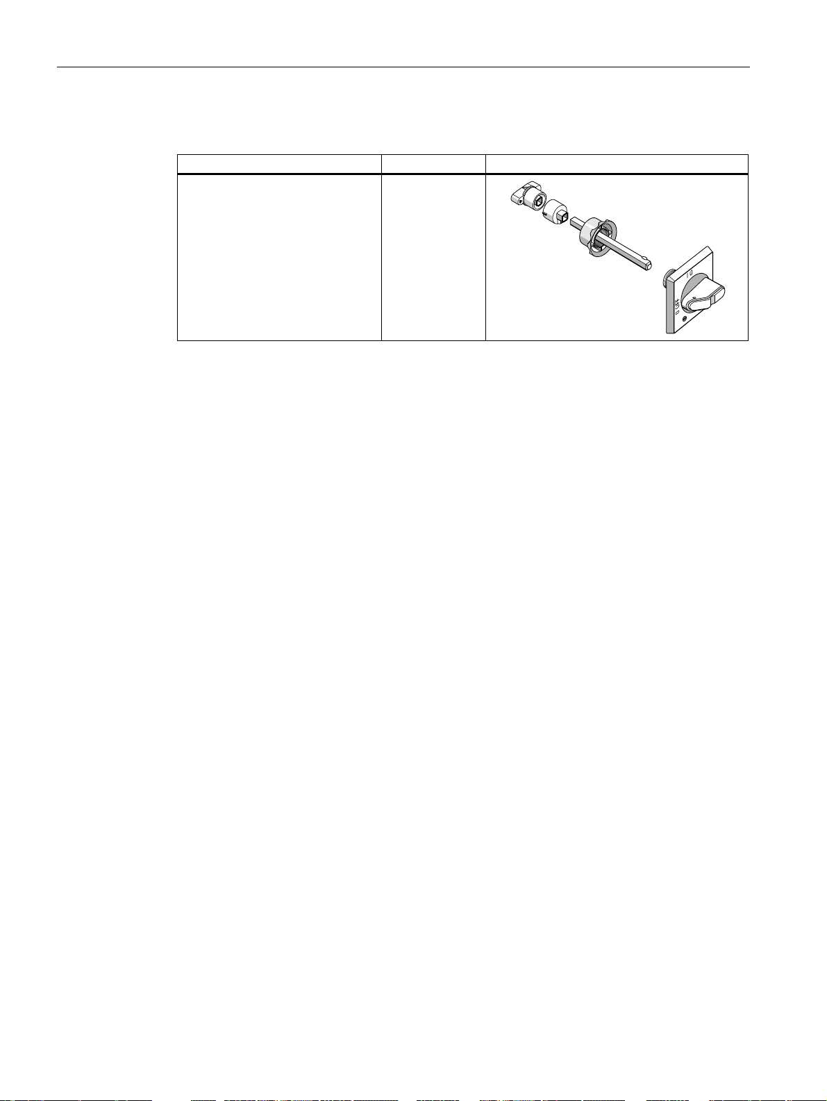
Door-coupling rotary operating mechanism
System component Order number Image
Door-coupling rotary operating
mechanism
- 130 mm long
EMERGENCY OFF door-coupling
rotary operating mechanism
- 130 mm long
3RV1926-0B
3RV1926-0C
SIRIUS 3RA6 Compact Starter
24 System Manual, 02/2008, GWA 4NEB 560 0601-02 DS 02

Configuration
4.1 SIRIUS 3RA6 compact starter
Assembly group installation
The module can be installed horizontally (i.e. on a vertically installed DIN rail) or vertically
(i.e. on a horizontally installed DIN rail).
Safe isolation
The following limit values must be observed to ensure safe isolation of the compact starters
in accordance with IEC / EN 60947-1:
● Control circuit to internal auxiliary circuit: 250 V
● Internal auxiliary/control circuit to internal auxiliary/control circuit: 250 V
● Internal auxiliary/control circuit to external auxiliary circuit: 400 V
● Main circuit to internal auxiliary/control circuit: 400 V
● Main circuit to external auxiliary circuit: 400 V
4
In order for the "safe isolation" of circuits to be achieved, an individual fault must not be able
to trigger a voltage overspill from one circuit into another. The kinds of fault to be taken into
account include twisted or loose conductive parts, twisted solder pins, broken winding wire,
missing screws or broken barriers within a device.
Cabinet types
The system can be installed inside a central control cabinet or a distributed control box.
Grounding measures
No grounding measures are necessary.
SIRIUS 3RA6 Compact Starter
System Manual, 02/2008, GWA 4NEB 560 0601-02 DS 02
25
Configuration
4.1 SIRIUS 3RA6 compact starter
Required control power supply
Depending on the version, the compact starter requires the following control power supply
(AC/DC):
● 24 V
● 42 to 70 V
● 110 to 240 V
Operating temperature
The compact starter has been designed for use with ambient temperatures ranging from
- 20 °C to + 40 °C.
Derating
Within the temperature range + 40 °C to + 60 °C, derating of the compact starter's
permissible rated current is necessary if:
● Several compact starters are installed side by side on a vertical DIN rail without any
space in between.
● Several compact starters are installed side by side in a SIRIUS 3RA6 infeed system
without any space in between.
Internal control cabinet temperatures Permissible rated current I
+ 40 °C 100% of I
+ 60 °C 80% of I
Maximum rated current
Depending on the current setting range, the following maximum rated currents apply to the
compact starter:
Table 4-1 Maximum rated current (3RA6 compact starter)
Current setting range Max. rated current
0.1 to 0.4 A 0.4 A
0.32 to 1.25 A 1.25 A
1 to 4 A 4 A
3 to 12 A 12 A
8 to 32 A 32 A
r max
r max
r max
SIRIUS 3RA6 Compact Starter
26 System Manual, 02/2008, GWA 4NEB 560 0601-02 DS 02

Configuration
4.1 SIRIUS 3RA6 compact starter
Short-circuit protection
The compact starter has a rated ultimate short-circuit breaking capacity ICU of 53 kA at
400 V. If the short-circuit current at the installation point exceeds the compact starter's
specified rated ultimate short-circuit breaking capacity, then you will need to use a backup
fuse. It is also possible to install an upstream circuit breaker with limiter function.
Combining compact starters with SIRIUS circuit breakers
The compact starter's connecting terminals are compatible with size S0 circuit breakers from
the SIRIUS 3RV range.
Distance from neighboring components
When installing compact starters, the following distances from grounded or live parts and
from neighboring components must be observed in accordance with IEC / EN 60947-6-2.
● Lateral distance from grounded parts: 10 mm
● Arcing space, top and bottom: 30 mm
!
!
!
!
Figure 4-1 Distance of compact starter from neighboring components (dimensions in mm)
(1) 3RA61 compact starter direct starter
(2) 3RA62 compact starter reversing starter
SIRIUS 3RA6 Compact Starter
System Manual, 02/2008, GWA 4NEB 560 0601-02 DS 02
27
Configuration
4.2 Supply possibilities in main circuit
4.2 Supply possibilities in main circuit
The following supply options are available for the compact starter's main circuit:
● Infeed via parallel wiring of individual compact starters
● Infeed via SIRIUS infeed system for 3RA6
● Infeed via 3-phase bus bars
● Infeed via 8US busbar adapter
If the creepages and clearances specified by UL 508 also need to be observed, then special
infeed terminals are available for the relevant infeed systems.
According to UL 508, these infeed terminals are not required for MSP (Manual Starter
Protector).
4.2.1 SIRIUS infeed system for 3RA6
Maximum rated current
The following maximum rated currents apply to the components of the SIRIUS infeed
system for 3RA6:
Table 4-2 Maximum rated current (infeed system for 3RA6)
Components Order number Max rated current I
Left infeed, 50/70 mm² screw terminal with
three slots, outgoing terminals with screw-type
connection technology, incl. PE bar
Left infeed, 50/70 mm² screw terminal with
three slots, outgoing terminals with springloaded connection technology, incl. PE bar
Left infeed, 25/35 mm² screw terminal with
three slots, outgoing terminals with screw-type
connection technology, incl. PE bar
Left infeed, 25/35 mm² screw terminal with
three slots, outgoing terminals with springloaded connection technology, incl. PE bar
Left or right infeed, 25/35 mm², with springloaded connection technology
Extension connector 3RA6890-1AB 63 A
3RA6813-8AB 100 A
3RA6813-8AC 100 A
3RA6812-8AB 63 A
3RA6812-8AC 63 A
3RA6830-5AC 63 A
r max
SIRIUS 3RA6 Compact Starter
28 System Manual, 02/2008, GWA 4NEB 560 0601-02 DS 02
 Loading...