

Siemens SIRIUS, SIRIUS 3RA User Manual
Industrial Controls
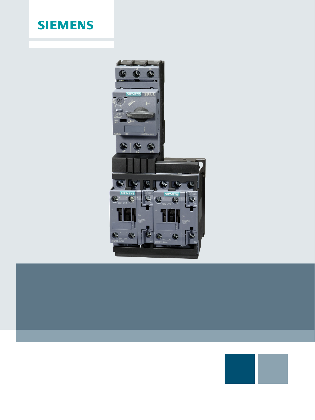
Load Feeders
SIRIUS - SIRIUS 3RA Load Feeders
GerätehandbuchManual
Edition
09/2016
siemens.com


SIRIUS - SIRIUS 3RA load feeders
___________________
___________________
___________________
___________________
___________________
___________________
___________________
___________________
___________________
___________________
___________________
___________________
___________________
___________________
___________________
Industrial Controls
Load feeders
SIRIUS - SIRIUS 3RA load feeders
Manual
09/2016
A5E03656507520A/RS
Introduction
1
Standards
2
Product description
3
Product combinations
4
Functions
5
Configuration
6
Mounting
7
Connection
8
Operation
9
Accessories
10
Technical data
11
Circuit diagrams
12
Types of coordination
A
References
B
Dimension drawings
(dimensions in mm)
C
-AB/003
Siemens AG
Division Digital Factory
Postf
90026 NÜRNBERG
GERMANY
3ZX1012-0RA21-5AC1
Ⓟ
Copyright © Siemens AG 2011.
All rights reserved
Legal information
Warning notice system
DANGER
indicates that death or severe personal injury will result if proper precautions are not taken.
WARNING
indicates that death or severe personal injury may result if proper precautions are not taken.
CAUTION
indicates that minor personal injury can result if proper precautions are not taken.
NOTICE
indicates that property damage can result if proper precautions are not taken.
Qualified Personnel
personnel qualified
Proper use of Siemens products
WARNING
Siemens products may only be used for the applications described in the catalog and in the relevant technical
ambient conditions must be complied with. The information in the relevant documentation must be observed.
Trademarks
Disclaimer of Liability
This manual contains notices you have to observe in order to ensure your personal safety, as well as to prevent
damage to property. The notices referring to your personal safety are highlighted in the manual by a safety alert
symbol, notices referring only to property damage have no safety alert symbol. These notices shown below are
graded according to the degree of danger.
If more than one degree of danger is present, the warning notice representing the highest degree of danger will
be used. A notice warning of injury to persons with a safety alert symbol may also include a warning relating to
property damage.
The product/system described in this documentation may be operated only by
task in accordance with the relevant documentation, in particular its warning notices and safety instructions.
Qualified personnel are those who, based on their training and experience, are capable of identifying risks and
avoiding potential hazards when working with these products/systems.
Note the following:
documentation. If products and components from other manufacturers are used, these must be recommended
or approved by Siemens. Proper transport, storage, installation, assembly, commissioning, operation and
maintenance are required to ensure that the products operate safely and without any problems. The permissible
All names identified by ® are registered trademarks of Siemens AG. The remaining trademarks in this publication
may be trademarks whose use by third parties for their own purposes could violate the rights of the owner.
We have reviewed the contents of this publication to ensure consistency with the hardware and software
described. Since variance cannot be precluded entirely, we cannot guarantee full consistency. However, the
information in this publication is reviewed regularly and any necessary corrections are included in subsequent
editions.
for the specific
ach 48 48
09/2016 Subject to change

Table of contents
1 Introduction ............................................................................................................................................. 7
2 Standards ............................................................................................................................................. 13
3 Product description ............................................................................................................................... 15
4 Product combinations ............................................................................................................................ 23
5 Functions .............................................................................................................................................. 25
6 Configuration ........................................................................................................................................ 27
7 Mounting ............................................................................................................................................... 33
1.1 Responsibility of the user for system configuration and functionality ....................................... 7
1.2 Purpose of the manual .............................................................................................................. 7
1.3 Required basic knowledge ........................................................................................................ 8
1.4 Scope of the manual ................................................................................................................. 8
1.5 Siemens Industry Online Support ............................................................................................. 9
1.6 Further documentation ............................................................................................................ 10
1.7 Siemens Industry Online Support app .................................................................................... 11
1.8 Recycling and disposal ........................................................................................................... 11
1.9 Technical Assistance .............................................................................................................. 12
3.1 Overview ................................................................................................................................. 15
3.2 Device versions ....................................................................................................................... 15
3.2.1 Pre-assembled complete devices ........................................................................................... 18
3.2.2 Self-assembled load feeders .................................................................................................. 19
3.3 Applications ............................................................................................................................. 22
3.4 Application environment.......................................................................................................... 22
6.1 SIRIUS system configurator ................................................................................................... 27
6.2 Use of 3RA2 load feeders with highly energy-efficient motors (IE3) ...................................... 28
6.2.1 General information on the startup characteristics of highly energy-efficient motors
(IE3) ........................................................................................................................................ 28
6.2.1.1 Short-circuit detection ............................................................................................................. 28
6.2.1.2 Making and breaking capacity of motor starter protectors ...................................................... 28
6.2.1.3 Rated motor current/setting scale ........................................................................................... 29
6.2.2 Optimization of 3RV2 motor starter protectors for IE3 motors ............................................... 29
6.2.3 Technical modifications/restrictions of 3RV2 motor starter protectors ................................... 31
7.1 Installation guidelines.............................................................................................................. 33
7.1.1 Minimum clearances to grounded or live parts (400 V / 500 V / 690 V AC) ........................... 33
7.1.2 Mounting variants under different conditions and frequency of use ....................................... 36
7.1.3 Permissible assembly types and derating .............................................................................. 41
SIRIUS - SIRIUS 3RA load feeders
Manual, 09/2016, A5E03656507520A/RS-AB/003
5

Table of contents
8 Connection .......................................................................................................................................... 121
9 Operation ............................................................................................................................................. 123
10 Accessories ......................................................................................................................................... 125
11 Technical data ..................................................................................................................................... 133
12 Circuit diagrams ................................................................................................................................... 135
A Types of coordination ........................................................................................................................... 137
B References .......................................................................................................................................... 139
C Dimension drawings (dimensions in mm) ............................................................................................. 143
Index ................................................................................................................................................... 167
7.2 Mounting and disassembling load feeders ............................................................................ 47
7.2.1 Overview ................................................................................................................................ 47
7.2.2 Load feeder with screw-type connection system ................................................................... 48
7.2.3 Load feeder with spring-loaded connection system ............................................................... 51
7.2.4 Load feeder with hybrid connection ....................................................................................... 61
7.3 Assembly and disassembly with different mounting systems ................................................ 66
7.3.1 On DIN rails without DIN rail adapter ..................................................................................... 67
7.3.2 On DIN rail with DIN rail adapter ............................................................................................ 69
7.3.2.1 Mounting direct-on-line starters and reversing starters on DIN rail adapters (sizes S00
and S0) ................................................................................................................................... 74
7.3.2.2 Mounting direct-on-line starters and reversing starters on DIN rail adapters (size S2) ......... 77
7.3.2.3 Mounting direct-on-line starters and reversing starters on DIN rail adapters (size S3) ......... 83
7.3.3 On busbar system .................................................................................................................. 90
7.3.4 Mounting on base plate ........................................................................................................ 113
7.3.4.1 Mounting on base plate without DIN rail adapter ................................................................. 113
7.3.4.2 Mounting on base plate with DIN rail adapter ...................................................................... 116
10.1 Overview .............................................................................................................................. 125
10.2 Accessories for constructing contactor assemblies for reversing and star-delta (wye-
delta) start ............................................................................................................................ 126
10.3 Link modules ........................................................................................................................ 126
10.4 Accessories for DIN rail mounting........................................................................................ 129
10.5 Accessories for busbar mounting......................................................................................... 131
11.1 Technical data in Siemens Industry Online Support ............................................................ 133
11.2 Overview tables.................................................................................................................... 133
12.1 CAx data .............................................................................................................................. 135
B.1 References ........................................................................................................................... 139
B.2 Manuals - SIRIUS Modular System ..................................................................................... 140
B.3 More information .................................................................................................................. 142
C.1 CAx data .............................................................................................................................. 143
C.2 3RA2 fuseless load feeders – Size S00 to S3 for DIN rail ................................................... 144
C.3 3RA2 fuseless load feeders – Size S00 to S2 for 60 mm busbar systems.......................... 158
SIRIUS - SIRIUS 3RA load feeders
6 Manual, 09/2016, A5E03656507520A/RS-AB/003

1
1.1
Responsibility of the user for system configuration and functionality
Note
When designing a system, comply with all valid national installation specifications and
standards.
1.2
Purpose of the manual
Fuseless load feeders are device combinations comprising a 3RV2 motor starter protector
for overload and short-circuit protection and a 3RT2 contactor for normal switching.
The SIRIUS portfolio features two different configuration options for fuseless load feeders:
● 3RA2 tested pre-assembled complete devices
● Tested combinations of individual devices
Siemens AG, its regional offices, and associated companies (hereinafter referred to as
"Siemens") cannot guarantee all the properties of an overall installation or machine that has
not been designed by Siemens.
Nor can Siemens assume liability for recommendations that appear or are implied in the
following description. No new guarantee, warranty, or liability claims beyond the scope of the
Siemens general terms of supply are to be derived or inferred from the following description.
This manual describes the 3RA21/3RA22 fuseless load feeders and provides the following
information:
● Information about the different mounting variants of the fuseless load feeders.
● Information on necessary hardware components.
● Information on installing, connecting and operating the fuseless load feeders.
● Technical information such as dimension drawings and unit wiring diagrams.
The information in this manual enables you to configure and commission the fuseless load
feeders.
SIRIUS - SIRIUS 3RA load feeders
Manual, 09/2016, A5E03656507520A/RS-AB/003
7

Introduction
1.3
Required basic knowledge
1.4
Scope of the manual
1.3 Required basic knowledge
To understand these operating instructions you should have a general knowledge of
automation engineering and low-voltage switchgear.
The manual is valid for these fuseless load feeders. It contains a description of the devices
that is valid at the time of publication.
SIRIUS - SIRIUS 3RA load feeders
8 Manual, 09/2016, A5E03656507520A/RS-AB/003

Introduction
1.5
Siemens Industry Online Support
Information and Service
Link:
Product support
FAQs
Manuals/operating instructions
Certificates
Characteristic curves
Product announcements
Downloads
Application examples
Technical data
Link:
1.5 Siemens Industry Online Support
In Siemens Industry Online Support, you can obtain up-to-date information from our global
support database quickly and simply. To accompany our products and systems, we offer a
wealth of information and services that provide support in every phase of the lifecycle of your
machine or plant – from planning and implementation, through commissioning, up to
maintenance and modernization:
● Product support
● Application examples
● Services
● Forum
● mySupport
Siemens Industry Online Support (https://support.industry.siemens.com/cs/ww/en)
You will find here all the information and comprehensive know-how covering all aspects of
your product:
●
Our answers to frequently asked questions.
●
Read online or download, available as PDF or individually configurable.
●
Clearly sorted according to approving authority, type and country.
●
For support in planning and configuring your system.
●
The latest information and news concerning our products.
●
You can find here updates, service packs, HSPs and much more for your product.
●
Function blocks, background and system descriptions, performance statements,
demonstration systems, and application examples, clearly explained and represented.
●
Technical product data for support in planning and implementing your project.
Product support (https://support.industry.siemens.com/cs/ww/en/ps)
SIRIUS - SIRIUS 3RA load feeders
Manual, 09/2016, A5E03656507520A/RS-AB/003
9

Introduction
mySupport
Personal messages
Inquiries
Notifications
Filters
Favorites / Tags
Entries last viewed
Documentation
Personal data
CAx data
1.6
Further documentation
1.6 Further documentation
With "mySupport", your personal workspace, you get the very best out of your Industry
Online Support. Everything to enable you to find the right information every time.
The following functions are now available:
●
Your personal mailbox for exchanging information and managing your contacts
●
Use our online form for specific solution suggestions, or send your technical inquiry
directly to a specialist in Technical Support
●
Make sure you always have the latest information - individually tailored to your needs
●
Simple management and re-use of your filter settings from Product Support and the
Technical Forum
●
Create your own knowledge database by assigning "Favorites" and "Tags" to documents
– simply and efficiently
●
Clear presentation of your last viewed entries
●
Configure your individual documentation from different manuals – quickly and without
complications
●
Change personal data and contact information here
●
Simple access to thousands of items of CAx data such as 3D models, 2D dimension
drawings, EPLAN macros and much more
SIRIUS - SIRIUS 3RA load feeders
10 Manual, 09/2016, A5E03656507520A/RS-AB/003
To install and connect the fuseless load feeders, you require the operating instructions of the
load feeders used.
You can find a list of operating instructions and an overview of the manuals pertaining to the
SIRIUS modular system in the Appendix "References (Page 139)".
Introduction
1.7
Siemens Industry Online Support app
Siemens Industry Online Support app
Link for Android
Link for iOS
Link for Windows Phone
1.8
Recycling and disposal
1.7 Siemens Industry Online Support app
You can use the Siemens Industry Online Support app to access all the device-specific
information available on the Siemens Industry Online Support portal for a particular article
number, including operating instructions, manuals, datasheets, FAQs etc.
The Siemens Industry Online Support app is available for iOS, Android or Windows Phone
devices. You can download the app from the following links:
These devices can be recycled thanks to their low pollutant content. For environmentallyfriendly recycling and disposal of your electronic waste, please contact a company certified
for the disposal of electronic waste.
SIRIUS - SIRIUS 3RA load feeders
Manual, 09/2016, A5E03656507520A/RS-AB/003
11

Introduction
1.9
Technical Assistance
Up-to-the-minute information
Technical Assistance:
or on the Internet at:
1.9 Technical Assistance
You can obtain further assistance by calling the following numbers:
Telephone: +49 (911) 895-5900 (8 a.m. to 5 p.m. CET)
Fax: +49 (911) 895-5907
E-mail: (mailto:technical-assistance@siemens.com)
Internet: (http://www.siemens.com/sirius/technical-assistance)
SIRIUS - SIRIUS 3RA load feeders
12 Manual, 09/2016, A5E03656507520A/RS-AB/003

2
Types of coordination
Approvals/Test reports
Reference
Fuseless load feeders are manufactured and tested in accordance with IEC 60947 – Part 1
and Part 2.
Types of coordination are important selection criteria for fuseless load feeders. They are
defined in the appendix, under "Types of coordination (Page 137)".
Extensive approvals and test certificates are available for 3RA2 pre-assembled complete
devices. If you assemble the load feeders yourself, all approvals and test certificates of the
individual devices and the certificates for type-tested combinations apply.
The standards from Catalog IC 10 "SIRIUS Industrial Controls" in the appendix always apply.
You will find extracts from the most important standards relating to the devices from the
SIRIUS modular system on the Internet
(http://www.siemens.com/automation/service&support) ("SIRIUS - System Overview", Article
Number: 3ZX1012-0RA01-5AC1).
SIRIUS - SIRIUS 3RA load feeders
Manual, 09/2016, A5E03656507520A/RS-AB/003
13

Standards
SIRIUS - SIRIUS 3RA load feeders
14 Manual, 09/2016, A5E03656507520A/RS-AB/003

3
3.1
Overview
Fuseless load feeders
3.2
Device versions
Fuseless load feeders are device combinations comprising a 3RV motor starter protector for
overload and short-circuit protection and a 3RT contactor for normal switching. The SIRIUS
portfolio features two different configuration options for fuseless load feeders.
● 3RA2 tested pre-assembled complete devices (sizes S00 to S2 only)
● Tested combinations of individual devices
The modular standard components in the SIRIUS modular system are ideally matched and
support the simple configuration of fuseless load feeders. The load feeders are also
available as 3RA2 complete devices.
Both options are characterized by the following features.
● Type of coordination 1 or 2
● Rated control supply voltage
● Mounting on busbar or DIN rail
● Screw or spring-loaded connection
A detailed overview of the fuseless load feeders product range appears below.
SIRIUS - SIRIUS 3RA load feeders
Manual, 09/2016, A5E03656507520A/RS-AB/003
15
Product description
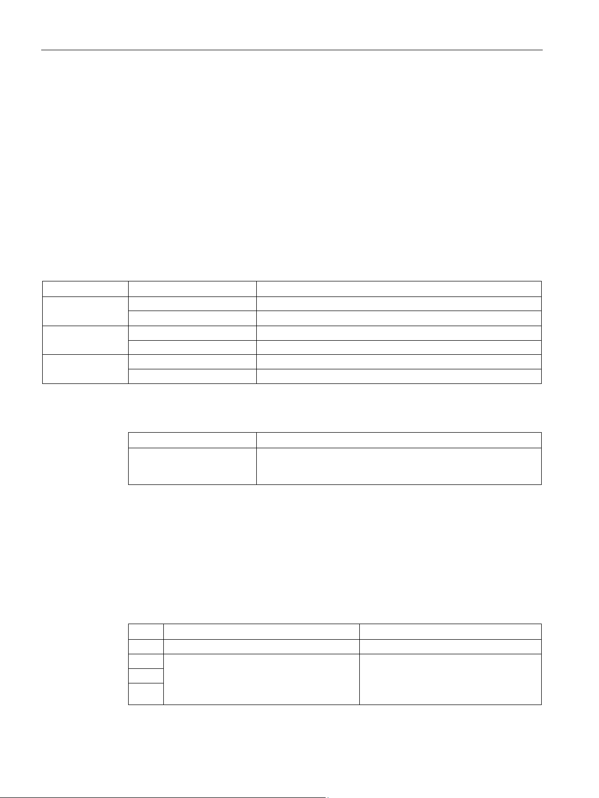
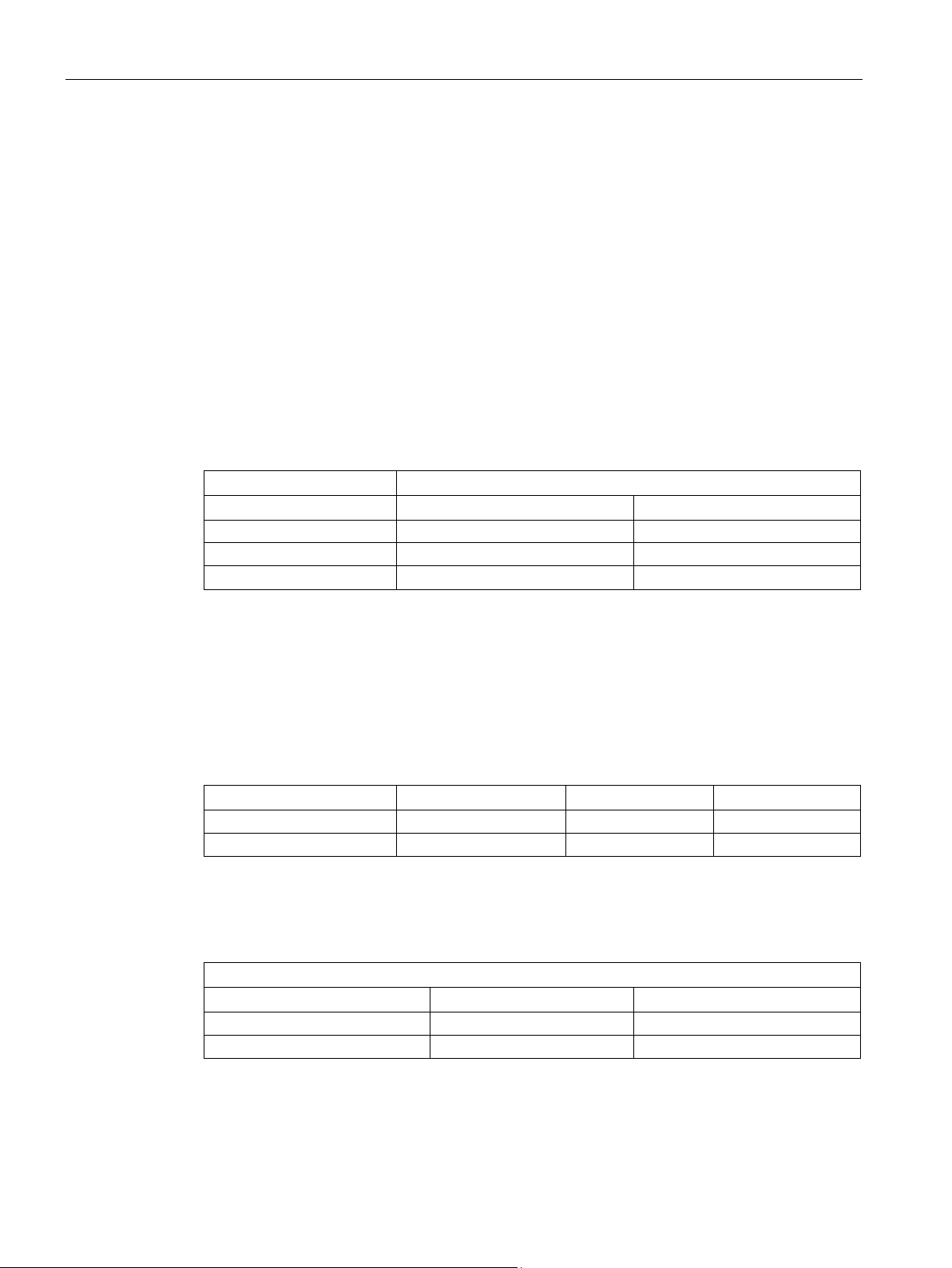
Types of coordination
Size
Type of coordination
Power of three-phase motor
1
0.06 to 7.5 kW
1
7.5 to 15 kW
2
1.5 to 15 kW
1
15 kW … 30 / 37 kW (max. 65 A)
2
15 kW … 30 / 37 kW (max. 65 A)
Reference
More information ...
Can be found in...
(Article Number: 3ZX1012-0RA21-1AC0)
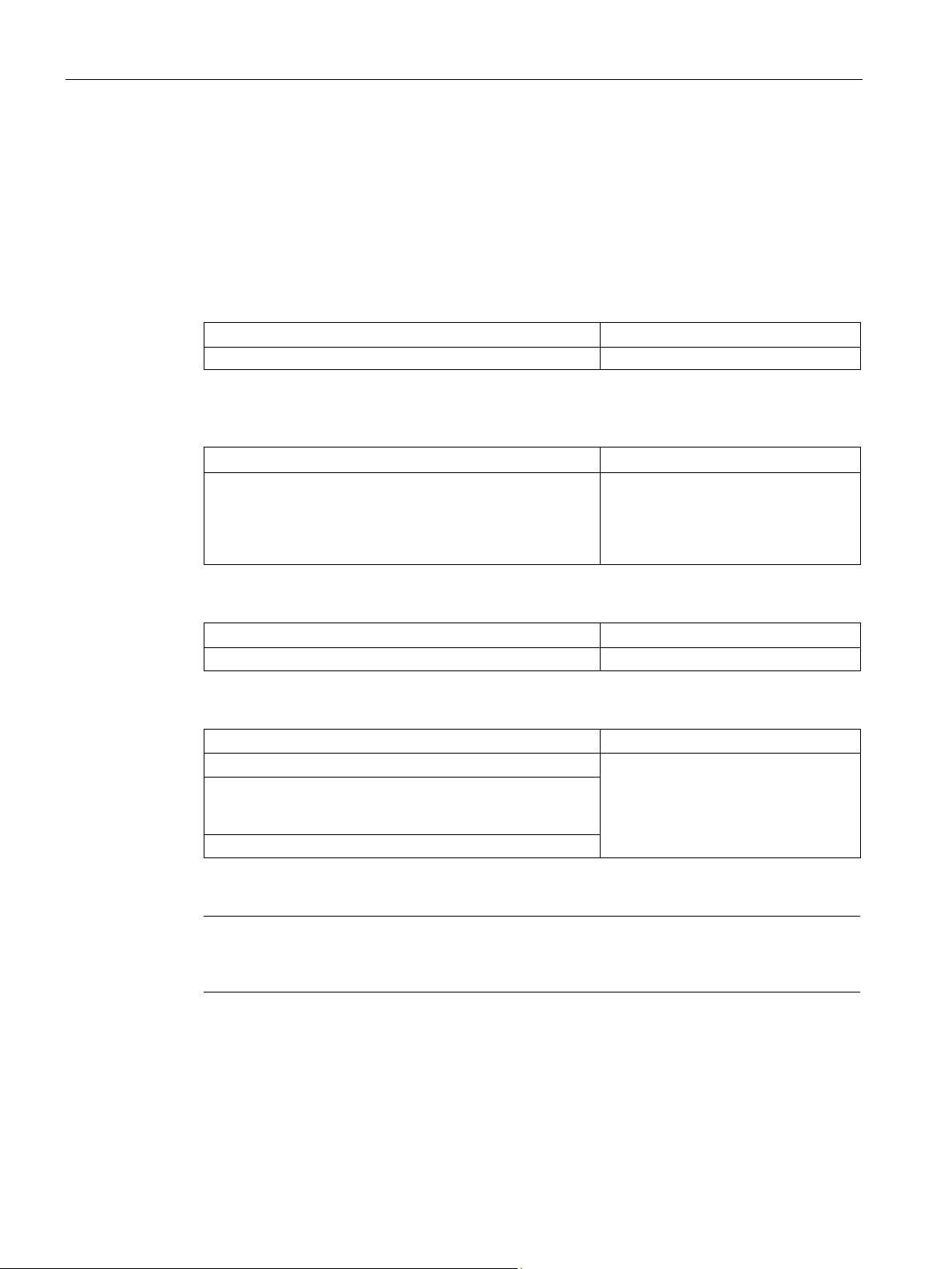
Auxiliary contacts
Size
Direct feeder
Reversing feeder
S00
1 NO contact is integrated in the contactor.
1 NC contact is integrated in the contactor.
S0
S2
3.2 Device versions
Fuseless load feeders up to 38 A (discrete configuration of individual devices with
connecting cables) and 32 A (pre-assembled complete devices or configuration with link
module) can be assembled in sizes S00 and S0.
An assembly up to 80 A (discrete configuration of individual devices with connecting cables)
and 65 A (as pre-assembled complete devices, or configuration with link module) is possible
in size S2.
An assembly up to 100 A (discrete configuration of individual devices with connecting
cables) is possible in size S3.
The table below lists the maximum power of the three-phase motor for pre-assembled
3RA2 complete devices based on the type of coordination at a voltage of 400 V AC.
Table 3- 1 Motor starter protector sizes
S00
2 0.06 to 1.5 kW
S0
S2
About approved load feeders in the configuration manual entitled "Configuring SIRIUS Innovations
- Selection data for load feeders in fuseless and fused designs"
The following auxiliary contacts are integrated into fuseless load feeders dependent upon
size.
Table 3- 2 Integrated auxiliary contacts
1 NO contact and 1 NC contact are integrated
in the contactor. The user can decide how the
S3
SIRIUS - SIRIUS 3RA load feeders
NC contact is assigned.
16 Manual, 09/2016, A5E03656507520A/RS-AB/003
1 NO contact and 1 NC contact are
integrated in the contactor. The NC contact
is assigned to the interlock.

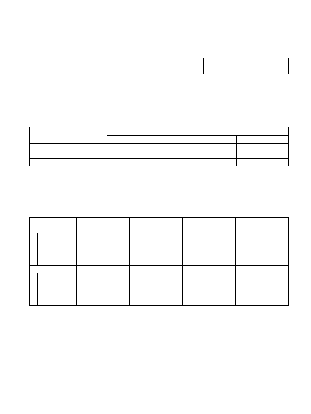
Product description
Assembly/Installation
Starter combination
Direct-on-line starter
Reversing starter
Size
S00
S0
S2
S3
S00
S0
S2
S3
Mounting on a standard rail
without adapter
Mounting on 8US busbar
adapter
Mounting on base plate
Direct ✓ ✓ ✓ — ✓ ✓ ✓ —
With DIN rail adapter
✓ ✓ ✓ ✓ ✓ ✓ ✓
✓
1)
2)
3)
Mounting on 1 or 2 DIN rails
3.2 Device versions
The devices are prepared for DIN rail mounting, for mounting on a 60 mm busbar or for
mounting on a base plate.
Table 3- 3 Mounting options
Snap-on mounting
✓1) ✓1) ✓2) — ✓1) — ✓2) —
With DIN rail adapter ✓3) ✓3) ✓2) ✓2) ✓3) ✓3) ✓2) ✓2)
With 8US busbar
✓ ✓ ✓ — ✓ ✓ ✓ —
Mounting on 1 DIN rail
Mounting on 2 DIN rails
SIRIUS - SIRIUS 3RA load feeders
Manual, 09/2016, A5E03656507520A/RS-AB/003
17
Product description
3.2.1
Pre-assembled complete devices
Pre-assembled complete devices
Connection systems
Connection system
3RA2 pre-assembled complete devices
S00 / S0
S2
Screw terminals
✓
✓
Spring-loaded terminals
✓
---
1)
2)
S00 motor starter protector.
Rated powers
Powers
S00
S0
S2
Direct-on-line starter
≤ 7.5 kW (16 A)
15 kW (32 A)
30 / 37 kW (65 A)
Reversing starter
≤ 7.5 kW (16 A)
15 kW (32 A)
---
Control supply voltages of 3RA2 load feeders
Rated control supply voltages
S00
S0
S2
230 V AC / 50/60 Hz
230 V AC / 50 Hz
230 V AC / 50 Hz
24 V DC
24 V DC
20 ... 33 V AC/DC
3.2 Device versions
3RA2 fuseless load feeders are pre-assembled complete devices; they are delivered readywired and with all mechanical connections established. The devices are available in
sizes S00, S0 and S2 for direct-on-line start. Pre-assembled complete devices in size S00
and S0 are available for reversing start. The fuseless load feeders can be ordered with or
without pre-assembled busbar adapters for mounting on a DIN rail or busbar.
3RA2 fuseless load feeders are available with the following connection system options.
Table 3- 4 Connection systems available for 3RA2 fuseless load feeders
1) 2)
Ring cable lug connection --- ---
The link module for the S00 load feeder can also be used to mount an S00 contactor on an
S0 motor starter protector.
The link module for the S0 load feeder can also be used to mount an S0 contactor on an
3RA2 pre-assembled feeders are dimensioned for the following powers:
3RA2 pre-assembled feeders are available for the following rated control supply voltages:
SIRIUS - SIRIUS 3RA load feeders
18 Manual, 09/2016, A5E03656507520A/RS-AB/003

Product description
3.2.2
Self-assembled load feeders
Assembly of load feeders from individual devices
Combination
S00
S0
S2
S3
Motor starter protector and contactor
7.5 kW (16 A)
15 kW (32 A)
30 / 37 kW (65 A)
55 kW (100 A) 1)
contactor
1)
A DIN rail adapter shall be used for this combination
3.2 Device versions
Self-assembly load feeders comprising individual devices are available as an alternative to
the 3RA2 complete device. In the case of a discrete configuration of individual devices
without a link module, the values of the basic devices apply. The following components can
be combined via the intermediary of a link module.
Motor starter protector and soft starter 7.5 kW (16 A) 15 kW (32 A) 30 / 37 kW (65 A) 1) On request
Motor starter protector and solid-state
The modularity of the SIRIUS system means that the standard devices are perfectly matched
from both a mechanical and an electrical point of view. As a straightforward means of
assembling starter combinations, wiring kits are available for contactor assemblies for
reversing and star-delta (wye-delta) start for size S2 / S3 with screw terminals, and for
size S00 / S0 with various connection systems. Assembly kits are available for mounting
self-assembled load feeders on DIN rails or busbars.
— 7.5 kW (16 A) — —
SIRIUS - SIRIUS 3RA load feeders
Manual, 09/2016, A5E03656507520A/RS-AB/003
19
Product description
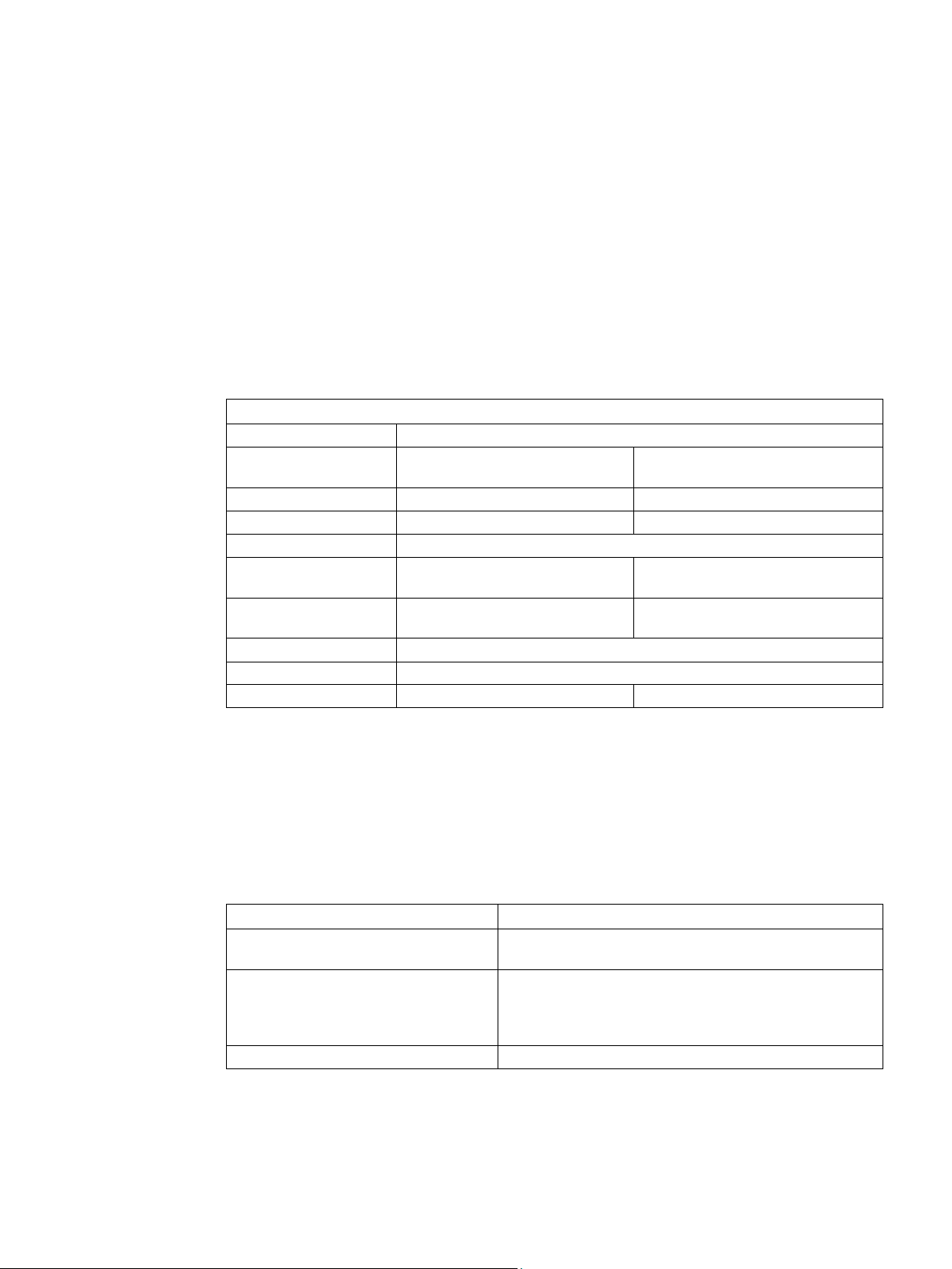
Assembly of three-part combinations with link module between the motor starter protector and the
contactor
Motor starter protector + contactor + electronic overload relay / 3RR monitoring relay
(size S00 / S0)
Thermal restrictions
Mechanical restrictions
No restrictions
DIN rail adapter required
Motor starter protector + contactor + electronic overload relay / 3RR monitoring relay
(size S2)
Thermal restrictions
Mechanical restrictions
Motor starter protector + contactor + solid-state overload relay (size S3)
Thermal restrictions
Mechanical restrictions
On request
On request
Motor starter protector + contactor + thermal overload relay (size S00 / S0)
Thermal restrictions:
Mechanical restrictions
horizontal installation)
Current derating to 87 % of In
Motor starter protector + contactor + thermal overload relay (size S2 / S3)
Note
A three
overload relay is not permissible for sizes S2 and
3.2 Device versions
You are basically advised to refrain from setting up combinations of a motor starter protector,
a contactor and an overload relay or a monitoring relay as a completely assembled threepart combination. If this should nevertheless be necessary, the following restrictions apply:
• At an ambient temperature of Ta = 40 °C
(no restrictions)
• At an ambient temperature of Ta = 60 °C
(clearance between the load feeders: ≥ 10 mm)
No restrictions
Reduce permissible ambient temperature by 20 K DIN rail adapter required
No side-by-side mounting
(≥ 10 mm clearance for vertical installation, > 20 mm for
-part combination consisting of a motor starter protector, a contactor and a thermal
SIRIUS - SIRIUS 3RA load feeders
20 Manual, 09/2016, A5E03656507520A/RS-AB/003
S3.
Product description
Reference
More information ...
Can be found in the chapter titled ...
About assembly kits for fuseless load feeders
Accessories (Page 125)
Connection systems
Connection system
Self-assembled fuseless load feeders
S00 / S0
S2
S3
Screw terminals ✓ ✓
✓
Spring-loaded connection
✓ 2) 2)
Ring cable lug connection
✓ 1)
—
—
1)
2)
In the case of size S2 and S3 devices, spring-loaded terminals are only possible in the auxiliary circuit.
Rated powers
Assembly
S00
S0
S2
S3
Direct-on-line starter
Ta 40 °C 1)
Ta 40 °C 1)
Ta 40 °C 1)
Separately wired
7.5 kW (16 A)
18.5 kW (38 A)
37 kW (80 A)
55 kW (100 A)
Reversing starter
Ta 40 °C 1)
Ta 40 °C 1)
Ta 40 °C 1)
Separately wired
7.5 kW (16 A)
18.5 kW (38 A)
37 kW (80 A)
55 kW (100 A)
Control supply voltages of load feeders
3.2 Device versions
Self-assembled fuseless load feeders are available with the following connection system
options.
Table 3- 5 Connection systems available for self-assembled fuseless load feeders
These versions can be snapped onto a DIN rail. Mounting on a busbar adapter is not possible.
The pre-assembled feeders are dimensioned for the following powers:
with link module 7.5 kW (14 A) at
60 °C 1)
T
a
7.5 kW (16 A) at
with link module 7.5 kW (14 A) at
T
60 °C 1)
a
7.5 kW (16 A) at
1)
Observe the installation guidelines (Page 36) when installing a load feeder with a link
module.
The contactors can be ordered with different rated control supply voltages as appropriate for
the application area of the fuseless load feeders.
15 kW (29 A) at
60 °C 1)
T
a
15 kW (32 A) at
15 kW (29 A) at
T
60 °C 1)
a
15 kW (32 A) at
37 kW (65 A) at
60 °C 1)
T
a
37 kW (65 A) at
T
60 °C 1)
a
45 kW (87 A) at
Ta 60 °C 1)
55 kW (100 A) at
45 kW (87 A) at
Ta 60 °C 1)
55 kW (100 A) at
SIRIUS - SIRIUS 3RA load feeders
Manual, 09/2016, A5E03656507520A/RS-AB/003
21

Product description
3.3
Applications
3.4
Application environment
3.3 Applications
Fuseless load feeders can be used anywhere in industry where fuse, contactor, and
overload relay combinations were previously used. The increased functionality of the motor
starter protector (unlike a fuse combination, it can be used as an EMERGENCY OFF and as
a disconnector) means that a fuseless load feeder is capable of solving numerous
applications easily.
3RA2 load feeders are climate-proof. They are designed for use in enclosed spaces in which
no severe operating conditions prevail (e.g. dust, caustic vapors, hazardous gases).
If they are to be installed in dusty or damp rooms, suitable enclosures must be provided.
SIRIUS - SIRIUS 3RA load feeders
22 Manual, 09/2016, A5E03656507520A/RS-AB/003
4
Device combination
Motor starter protector
Contactor1)
relay1)
Motor starter protector
Contactor
SIMOCODE pro1)
Motor starter protector
Contactor
SIRIUS 3RR monitoring relay1)
Motor starter protector
Reversing contactor assembly1)
(wye-delta) start
relay2)
(wye-delta) start
Motor starter protector
Solid-state contactor or solid-state reversing contactor
Motor starter protector
Solid-state contactor
SIRIUS 3RR monitoring relay
1)
2)
Also with 3RA27 communication connection or 3RA28 logic module
Reference
More information ...
Can be found ...
individual devices
Modular System (Page 140)".
3ZX1012-0RA21-1AB0).
About matching link modules
In the chapter titled "Link modules (Page 126)".
The SIRIUS modular system supports the assembly of load feeders for a whole variety of
requirements. The individual devices which can be combined are matched to one another
from both an electrical and a mechanical point of view.
The following fuseless device combinations have been tested according to IEC 60947-4-1:
Table 4- 1 Fuseless load feeders tested according to IEC 60947-4-1
Motor starter protector Contactor Thermal or electronic overload
Motor starter protector Contactor assembly for star-delta
Motor starter protector Contactor assembly for star-delta
Motor starter protector 3RW30, 3RW40, 3RW44 soft starters
Also with 3RA27 communication connection
Thermal or electronic overload
SIMOCODE pro2)
The configuration manual contains detailed information about individual device
combinations. The configuration manual describes fuseless and fused load feeders for
various line voltages.
About the mechanical combinations of
About approved load feeders in the configuration guide entitled "Configuring SIRIUS
In the "References" appendix under "Manuals - SIRIUS
Innovations - Selection data for load feeders in fuseless
and fused designs" (Article Number:
SIRIUS - SIRIUS 3RA load feeders
Manual, 09/2016, A5E03656507520A/RS-AB/003
23

Product combinations
SIRIUS - SIRIUS 3RA load feeders
24 Manual, 09/2016, A5E03656507520A/RS-AB/003

5
Pre-assembled load feeders
Self-assembled load feeders
Reference
More information ...
Can be found ...
- SIRIUS 3RV motor starter protectors" manual.
In the 3RA2 fuseless load feeder, the 3RV2 motor starter protector takes on the dual function
of overload protection and short-circuit protection. Upstream protective devices such as
melting fuses or limiters are superfluous, as the load feeder is capable of withstanding short
circuits up to 150 kA at 400 V.
The 3RT2 contactor is suitable for extremely complex switching tasks requiring maximum
endurance.
The trip class on all pre-assembled 3RA2 feeders is CLASS 10.
Thanks to the flexible SIRIUS modular system, load feeders can be assembled for the most
diverse requirements.
These load feeders can be fuseless or fused. Load feeders for starting motors can be
assembled for the following startup types, for example:
● Direct-on-line start
● Reversing start
● Star-delta (wye-delta) start
● Soft start
● Configuration with solid-state switching devices for high switching frequencies
In the case of a configuration with overload relay, a tripping class up to CLASS 30 can be
set. In the case of a configuration with SIMOCODE, a tripping class up to CLASS 40 can be
set.
About the functions of motor starter protectors In the "References" appendix under "Manuals -
SIRIUS Modular System (Page 140)" in the "SIRIUS
SIRIUS - SIRIUS 3RA load feeders
Manual, 09/2016, A5E03656507520A/RS-AB/003
25

Functions
SIRIUS - SIRIUS 3RA load feeders
26 Manual, 09/2016, A5E03656507520A/RS-AB/003

Configuration
6
Application planning
Reference
More information ...
Can be found ...
SIRIUS 3RT Contactors/Contactor Assemblies” manual.
motor starter protectors" manual.
3ZX1012-0RA21-1AB0).
6.1
SIRIUS system configurator
Reference
You will find detailed information about configuration in the configuration manual. The
configuration manual describes fuseless and fused load feeders for various line voltages.
About applications involving contactors In the "References" appendix under "Manuals - SIRIUS
Modular System (Page 140)" in the "SIRIUS -
About applications involving motor
starter protectors
About configuration in the configuration guide entitled "Configuring SIRIUS
In the "References" appendix under "Manuals - SIRIUS
Modular System (Page 140)" in the "SIRIUS - SIRIUS 3RV
Innovations - Selection data for load feeders in fuseless
and fused designs" (Article Number:
To assist you with configuration, the "SIRIUS system configurator" is at your disposal on the
Internet. Here, you can gather together all necessary products before the actual
configuration process and you can realize complete projects virtually.
You can find the "SIRIUS system configurator" on the Internet
(http://www.siemens.com/sirius/configurators).
SIRIUS - SIRIUS 3RA load feeders
Manual, 09/2016, A5E03656507520A/RS-AB/003
27

Configuration
6.2
Use of 3RA2 load feeders with highly energy-efficient motors (IE3)
6.2.1
General information on the startup characteristics of highly energy-efficient motors (IE3)
6.2.1.1
Short-circuit detection
6.2.1.2
Making and breaking capacity of motor starter protectors
6.2 Use of 3RA2 load feeders with highly energy-efficient motors (IE3)
Motor starter protectors have been conceived to protect and switch motors. They assume
the task of line protection in the event of an overload or short-circuit.
To this end, motor starter protectors are equipped with sensors for overload and short-circuit
detection and possess an interruption point for switching motor and short-circuit currents.
Without technical adaptation to the new highly energy-efficient motors (IE3), the problems
described below can arise.
In the event of unusually high currents in the electrical installation, short-circuit detection
serves to keep the thermal and dynamic load low and ensure safe shutdown. The response
threshold should lie above the currents that a starting motor causes. The dimensioning of a
system is influenced by the response value. The higher the response value, the higher the
chosen cable cross-sections to be protected must be. This increases costs in the system and
for the switching devices. This is why the response values have been adapted to the
previously typical motor starting currents.
The drawback of the new, more efficient motors (IE3) is that, on average, the locked rotor
and magnetization currents (inrush currents) arising at the moment of switching on are
considerably higher than in the case of the previous generations of motors. The spread of
locked rotor and inrush currents is very wide. Motors with high values can therefore cause
the motor starter protector's short-circuit detection to respond. This leads to unintentional
shutdown ("early tripping") during motor starting. Early tripping can occur whenever the
motor current lies in the top range of the motor starter protector's setting scale and a motor
with a high inrush current is used.
Making and breaking capacity tests are conducted in compliance with the standard under
three-phase AC loading with 10 to 8 times the rated current. In some cases, the locked rotor
and inrush currents of IE3 motors are clearly above these values. In isolated cases, current
spikes that arise during switching on can cause brief lifting of the contacts without triggering
a breaking operation by short-circuit detection.
Where the motor is switched on by a contactor, for example, the motor starter protector's
making/breaking capacity is irrelevant. In this case, the motor current is only carried. The
current that can be carried without any problems is normally higher than the switching
device's making/breaking capacity.
SIRIUS - SIRIUS 3RA load feeders
28 Manual, 09/2016, A5E03656507520A/RS-AB/003

Configuration
6.2.1.3
Rated motor current/setting scale
See also
6.2.2
Optimization of 3RV2 motor starter protectors for IE3 motors
6.2 Use of 3RA2 load feeders with highly energy-efficient motors (IE3)
For motor protection, the motor's rated current must be set on the motor starter protector's
setting scale. The new IE3 motors generally have lower rated currents. This can lead to
situations in which a motor starter protector with a lower rated current has to be chosen for
the same motor rating. Thus, the short-circuit detection response value also drops and can
lead to tripping during motor starting.
Short-circuit detection (Page 28)
The motor starter protectors have been revised in relation to the higher locked rotor currents
and inrush currents as follows:
● Raising of the lower short-circuit detection response tolerances without changes to t
max
imum values.
→ No change to system dimensioning
● Increase in the making / breaking capacity.
→ Far-reaching avoidance of restrictions due to increased motor starting currents
i
nrush currents, see the chapter "Technical modifications/restrictions of 3RV2 motor
starter protectors (Page 31)".
and
he
● Adaptation of some motor starter protector versions' overload releases and setting
scales.
→ Avoidance of using smaller motor starter protectors due to lower rated motor currents
(see chapter "Technical modifications/restrictions of 3RV2 motor starter protectors
(Page 31)")
In the case of motors with very high locked rotor and inrush currents, problems can arise
despite adaptations, e.g. undesired tripping on starting. It is recommended that motor starter
protectors be selected such that the setting does not need to be made in the upper range of
the setting scale. This reduces power loss in the device (cost saving and reduced
temperature rise in the control cabinet) and increases the distance from the short-circuit
releases' response limits.
SIRIUS - SIRIUS 3RA load feeders
Manual, 09/2016, A5E03656507520A/RS-AB/003
29

Configuration
Selection example
6.2 Use of 3RA2 load feeders with highly energy-efficient motors (IE3)
In this example, two motor starter protectors are compared with each other.
Rated motor current: 15 A
Motor starter protector A: Setting scale 10 ... 16 A
Motor starter protector B: Setting scale 14 ... 20 A
Motor starter protector B (14 ... 20 A) is recommended since its power loss is lower and it
has a higher distance to the response limits.
The power loss of motor starter protector B is approximately 35 % lower than that of motor
starter protector A.
The response limits of the short-circuit release always refer to the maximum setting value:
● In the case of motor starter protector A, the response value of the short-circuit release is
208 A (13 × 16 A).
At the setting value of 15 A, the distance to the response limit of the short-circuit release
is 13.86 times the current setting (208 A / 15 A =13.86).
● In the case of motor starter protector B, the response value of the short-circuit release is
260 A (13 × 20 A). With a setting value of 15 A, the distance to the response limit of th
s
hort-circuit release is 17.33 times the current setting (260 A / 15 A = 17.33).
e
In the present example, the distance to the response limit of 13.86 times the setting current
for motor starter protector A increases to 17.33 times the current setting for motor starter
protector B.
SIRIUS - SIRIUS 3RA load feeders
30 Manual, 09/2016, A5E03656507520A/RS-AB/003
 Loading...