

Page 1
Data sheet 3SK1111-1AW20
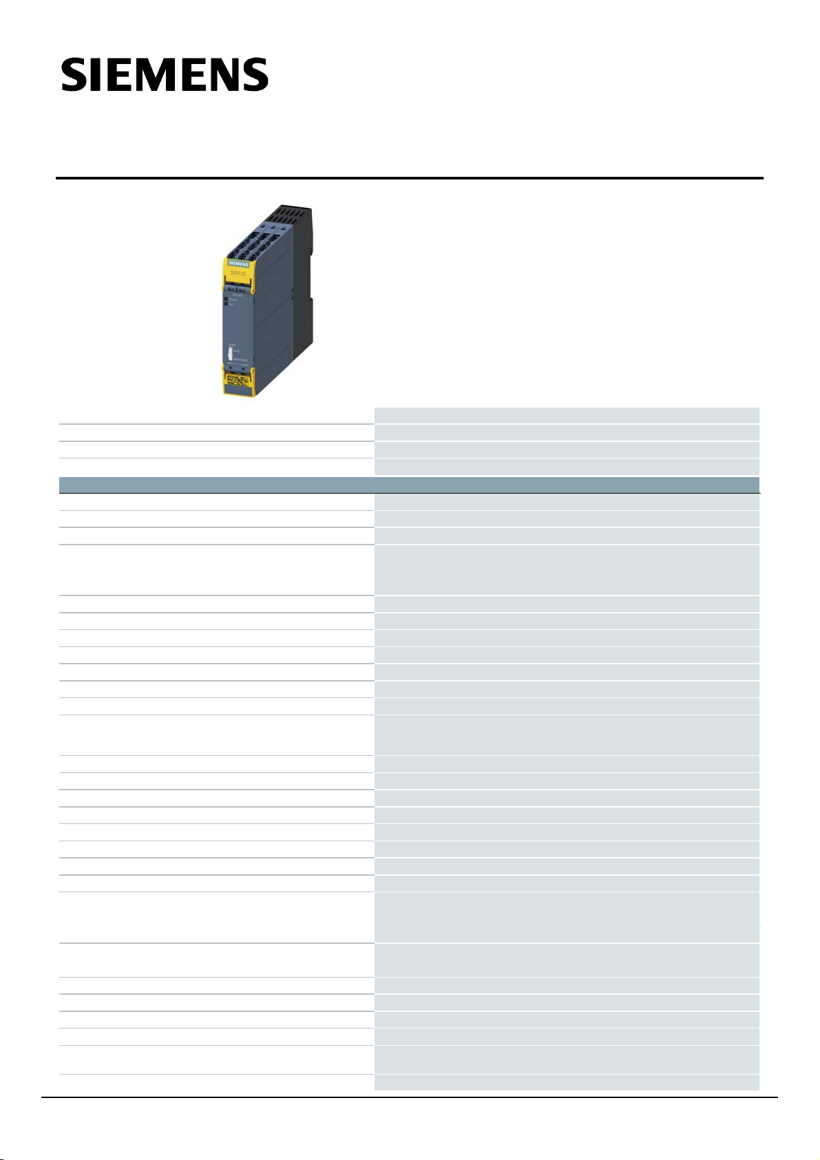
SIRIUS safety relay Basic unit Standard series Relay enabling circuits 3 NO
contacts plus Relay signaling circuit 1 NC contact Us = 110 - 240 V AC/DC 50/60
Hz screw terminal
product brand name
SIRIUS
product category
Safety relays
product designation
safety relays
design of the product
Relay enabling circuits
General technical data
protection class IP of the enclosure
IP20
touch protection against electrical shock
finger-safe
insulation voltage rated value
300 V
ambient temperature
● during storage
-40 ... +80 °C
● during operation
-25 ... +60 °C
air pressure according to SN 31205
90 ... 106 kPa
relative humidity during operation
10 ... 95 %
installation altitude at height above sea level maximum
4 000 m; Derating, see Product Notification 109792701
vibration resistance according to IEC 60068-2-6
5 ... 500 Hz: 0.75 mm
shock resistance
10g / 11 ms
surge voltage resistance rated value
4 000 V
EMC emitted interference
IEC 60947-5-1, Class A
installation environment regarding EMC
This product is suitable for Class A environments only. In household
environments, this device can cause unwanted radio interference. The user is
required to implement appropriate measures in this case.
overvoltage category
3
degree of pollution
3
reference code according to IEC 81346-2
F
power loss [W] maximum
2.5 W
number of sensor inputs 1-channel or 2-channel
1
design of the cascading
none
type of the safety-related wiring of the inputs
single-channel and two-channel
product feature cross-circuit-proof
Yes
Safety Integrity Level (SIL)
● according to IEC 62061
3
● according to IEC 61508
3
performance level (PL)
● according to ISO 13849-1
e
category according to EN ISO 13849-1
4
Safe failure fraction (SFF)
99 %
PFHD with high demand rate according to EN 62061
1.5E-9 1/h
PFDavg with low demand rate according to IEC 61508
1E-6
T1 value for proof test interval or service life according to
IEC 61508
20 a
hardware fault tolerance according to IEC 61508
1
3SK11111AW20
Page 1/5
10/20/2023
Subject to change without notice
© Copyright Siemens
Page 2

safety device type according to IEC 61508-2
Type A
Inputs/ Outputs
number of outputs as contact-affected switching element
● as NC contact
— for signaling function instantaneous contact
1
● as NO contact
— safety-related instantaneous contact
3
— safety-related delayed switching
0
stop category according to EN 60204-1
0
design of input
● cascading input/functional switching
No
● feedback input
Yes
● start input
Yes
type of electrical connection plug-in socket
No
operating frequency maximum
360 1/h
switching capacity current
● of the NO contacts of the relay outputs
— at DC-13
— at 24 V
5 A
— at 115 V
0.2 A
— at 230 V
0.1 A
— at AC-15
— at 115 V
5 A
— at 230 V
5 A
● of the NC contacts of the relay outputs
— at DC-13
— at 24 V
1 A
— at 115 V
0.2 A
— at 230 V
0.1 A
— at AC-15
— at 115 V
1.5 A
— at 230 V
1.5 A
thermal current of the switching element with contacts
maximum
5 A
total current maximum
12 A
operational current at 17 V minimum
5 mA
mechanical service life (operating cycles) typical
10 000 000
design of the fuse link for short-circuit protection of the NO
contacts of the relay outputs required
gL/gG: 6A or circuit breaker type A: 3A or circuit breaker type B: 2A or circuit
breaker type C: 1A
design of the fuse link for short circuit protection of the NC
contacts of the relay outputs required
Diazed or Neozed fuses, operating class gL/gG: 6 A or MCB type A: 2 A or
MCB type B: 2 A or MCB type C: 1 A
wire length
● for total of all sensor circuits with Cu 1.5 mm² and 150
nF/km maximum
2 000 m
make time with automatic start
● typical
110 ms
● at DC maximum
130 ms
● at AC maximum
130 ms
make time with automatic start after power failure
● typical
110 ms
● maximum
130 ms
make time with monitored start
● maximum
15 ms
● typical
15 ms
backslide delay time after opening of the safety circuits
typical
10 ms
backslide delay time in the event of power failure
● typical
200 ms
● maximum
300 ms
recovery time after opening of the safety circuits typical
10 ms
recovery time after power failure typical
0.32 s
pulse duration
3SK11111AW20
Page 2/5
10/20/2023
Subject to change without notice
© Copyright Siemens
Page 3

● of the sensor input minimum
150 ms
● of the ON pushbutton input minimum
0.015 s
Control circuit/ Control
type of voltage of the control supply voltage
AC/DC
control supply voltage frequency
● 1 rated value
50 Hz
● 2 rated value
60 Hz
control supply voltage
● at DC
— rated value
110 ... 240 V
● at AC
— at 50 Hz
— rated value
110 ... 240 V
— at 60 Hz
— rated value
110 ... 240 V
operating range factor control supply voltage rated value of
magnet coil
● at AC
— at 50 Hz
0.85 ... 1.1
— at 60 Hz
0.85 ... 1.1
● at DC
0.85 ... 1.1
Installation/ mounting/ dimensions
mounting position
any
required spacing for grounded parts at the side
5 mm
fastening method
screw and snap-on mounting
width
22.5 mm
height
100 mm
depth
121.6 mm
Connections/ Terminals
type of electrical connection
screw-type terminals
type of connectable conductor cross-sections
● solid
1x (0.5 ... 2.5 mm²), 2x (1.0 ... 1.5 mm²)
● finely stranded
— with core end processing
1x (0.5 ... 2.5 mm²), 2x (0.5 ... 1.0 mm²)
type of connectable conductor cross-sections for AWG
cables
● solid
1x (20 ... 14), 2x (18 ... 16)
● stranded
1x (20 ... 16), 2x (20 ... 16)
Product Function
product function parameterizable
Sensor floating / monitored start / automatic start
suitability for operation device connector 3ZY12
No
suitability for interaction press control
No
suitability for use
● safety switch
Yes
● monitoring of floating sensors
Yes
● monitoring of non-floating sensors
No
● magnetically operated switch monitoring
No
● safety-related circuits
Yes
Certificates/ approvals
General Product Approval
EMC
Confirmation
Functional
Safety/Safety of Machinery
Declaration of Conformity
Test Certificates
Marine / Shipping
3SK11111AW20
Page 3/5
10/20/2023
Subject to change without notice
© Copyright Siemens
Page 4

Type Examination Cer-
Marine / Shipping
other
Railway
Further information
tificate
Confirmation Confirmation
Siemens has decided to exit the Russian market (see here).
https://press.siemens.com/global/en/pressrelease/siemens-wind-down-russian-business
Siemens is working on the renewal of the current EAC certificates.
Please contact your local Siemens office on the status of validity of the EAC certification if you intend to import or offer to supply these products to an
EAC relevant market (other than the sanctioned EAEU member states Russia or Belarus).
Information on the packaging
https://support.industry.siemens.com/cs/ww/en/view/109813875
Information- and Downloadcenter (Catalogs, Brochures,…)
https://www.siemens.com/ic10
Industry Mall (Online ordering system)
https://mall.industry.siemens.com/mall/en/en/Catalog/product?mlfb=3SK1111-1AW20
Cax online generator
http://support.automation.siemens.com/WW/CAXorder/default.aspx?lang=en&mlfb=3SK1111-1AW20
Service&Support (Manuals, Certificates, Characteristics, FAQs,...)
https://support.industry.siemens.com/cs/ww/en/ps/3SK1111-1AW20
Image database (product images, 2D dimension drawings, 3D models, device circuit diagrams, EPLAN macros, ...)
http://www.automation.siemens.com/bilddb/cax_de.aspx?mlfb=3SK1111-1AW20&lang=en
Type Test Certific-
ates/Test Report
3SK11111AW20
Page 4/5
10/20/2023
Subject to change without notice
© Copyright Siemens
Page 5

Logic
Autostart / Monitored Start
42
34
24
14
A2-
41
33
23
13
IN
F/S
T4
IN2
T2
IN1
T1
A1+
-K
Logic
Autostart / Monitored Start
42
34
24
14
A2-
41
33
23
13
IN
F/S
T4
IN2
T2
IN1
T1
A1+
-K
last modified:
3SK11111AW20
Page 5/5
8/11/2023
10/20/2023
Subject to change without notice
© Copyright Siemens
 Loading...