

Page 1
SIREMOBIL Compact
DHHS Maintenance Instructions
SP
© Siemens AG 1996
The reproduction, transmission or
use of this document or its contents
is not permitted without express
written authority. Offenders will be
liable for damages. All rights,
including rights created by patent
grant or registration of a utility
model _or_ design,_are_ reserved.
English
Print No.: RXR2-130.101.02.03.02 Doc. Gen. Date: 08.97
Replaces: RXR2-130.101.02.01.02
Page 2

0 - 2 Revision
Chapter Page Revision
01 to 403
11 to 201
21 to 402
31 to 201
4 1 to 10 02
51 to 202
61 to 201
71 to 202
SIREMOBIL Compact RXR2-130.101.02 Page 2 of 4 Siemens AG
Rev. 03 08.97 TD SP 1 Medical Engineering
Page 3

Contents 0 - 3
Page
1 _______General information and overview_________________________________1 - 1
After completion of maintenance: . . . . . . . . . . . . . . . . . . . . . . . . . . . . 1 - 1
1 Required reference documents . . . . . . . . . . . . . . . . . . . . . . . . . . . . 1 - 2
2 Required test equipment . . . . . . . . . . . . . . . . . . . . . . . . . . . . . . . 1 - 2
3 Safety Notes. . . . . . . . . . . . . . . . . . . . . . . . . . . . . . . . . . . . . . 1 - 2
4 Notes for the Maintenance Instructions . . . . . . . . . . . . . . . . . . . . . . . . 1 - 2
2 _______Visual checks__________________________________________________2 - 1
1 Radiation protection . . . . . . . . . . . . . . . . . . . . . . . . . . . . . . . . . . 2 - 1
2 Checking the DHHS and Identification Labels . . . . . . . . . . . . . . . . . . . . 2 - 1
2.1 Location of the DHHS and Identification Label s. . . . . . . . . . . . . . . . . 2 - 2
3 _______Checking the function blocks and displays _________________________3 - 1
1 Checking the ”deadman” switch function . . . . . . . . . . . . . . . . . . . . . . . 3 - 1
1.1 Exposure. . . . . . . . . . . . . . . . . . . . . . . . . . . . . . . . . . . . . 3 - 1
1.2 Fluoroscopy . . . . . . . . . . . . . . . . . . . . . . . . . . . . . . . . . . . 3 - 1
2 Radiation indicators . . . . . . . . . . . . . . . . . . . . . . . . . . . . . . . . . . 3 - 1
3 Fluoroscopy timer . . . . . . . . . . . . . . . . . . . . . . . . . . . . . . . . . . . 3 - 2
4 Indication of X-ray tube potential and current . . . . . . . . . . . . . . . . . . . . . 3 - 2
5 Minimum source to skin distance . . . . . . . . . . . . . . . . . . . . . . . . . . . 3 - 2
4 _______Function tests _________________________________________________4 - 1
1 Checking the accuracy of the tube voltage . . . . . . . . . . . . . . . . . . . . . . 4 - 1
2 Reproducibility. . . . . . . . . . . . . . . . . . . . . . . . . . . . . . . . . . . . . 4 - 1
2.1 Measurement set-up. . . . . . . . . . . . . . . . . . . . . . . . . . . . . . . 4 - 1
2.2 Calculations . . . . . . . . . . . . . . . . . . . . . . . . . . . . . . . . . . . 4 - 2
3 Entrance exposure rate . . . . . . . . . . . . . . . . . . . . . . . . . . . . . . . . 4 - 3
4 Checking the central beam . . . . . . . . . . . . . . . . . . . . . . . . . . . . . . 4 - 4
4.1 Position of central beam in relation to the I.I. input . . . . . . . . . . . . . . . 4 - 4
5 Check the I.I. format. . . . . . . . . . . . . . . . . . . . . . . . . . . . . . . . . . 4 - 6
6 Check the smallest field size . . . . . . . . . . . . . . . . . . . . . . . . . . . . . 4 - 6
7 Cassette format . . . . . . . . . . . . . . . . . . . . . . . . . . . . . . . . . . . . 4 - 7
7.1 Cassette to radiation field . . . . . . . . . . . . . . . . . . . . . . . . . . . . 4 - 7
7.2 Center cassette to radiation field . . . . . . . . . . . . . . . . . . . . . . . . 4 - 9
5 _______Technical Data _________________________________________________5 - 1
Technical data for DHHS components . . . . . . . . . . . . . . . . . . . . . . . . . 5 - 1
X-Ray Controls and Generators . . . . . . . . . . . . . . . . . . . . . . . . . . . 5 - 1
Generator ratings: . . . . . . . . . . . . . . . . . . . . . . . . . . . . . . . . . . 5 - 1
Maximum deviations. . . . . . . . . . . . . . . . . . . . . . . . . . . . . . . . . 5 - 1
Tube Housing Assemblies. . . . . . . . . . . . . . . . . . . . . . . . . . . . . . 5 - 2
Definitions of the measurement bases of technique factors. . . . . . . . . . . . . 5 - 2
Siemens AG RXR2-130.101.02 Page 3 of 4 SIREMOBIL Compact
Medical Engineering Rev. 03 08.97 TD SP 1
Page 4

0 - 4 Contents
Page
6 ______ Final steps ____________________________________________________6 - 1
Final visual and function checks . . . . . . . . . . . . . . . . . . . . . . . . . . . . 6 - 1
7 ______ Changes to previous version_____________________________________7 - 1
SIREMOBIL Compact RXR2-130.101.02 Page 4 of 4 Siemens AG
Rev. 03 08.97 TD SP 1 Medical Engineering
Page 5

General information and overview 1
To ensure compliance with the applicable provisio ns of the Federal Performance Standard, the user of the equipment has to ensure that the maintenance procedure described
below is performed at intervals of si x months or less. In case the user does not comply
with these requirements, the manufactu rer can no longer be held liable.
If the results of any of the tests described in this document exceed the tolerances given,
the required adjustments must be performed.
Contact Siemens service.
After performing any adjustment, all appl icable tests must be repeated.
Customer: Customer No.: Room:
BZ-No.: Type No.: Serial No.:
1 - 1
After completion of maintenance: 1
I hereby certify t hat all proce dures described i n these main tenance instruc tions have been
completed as specified and that the tolerance values are within the accepted range.
_____________ __________________
Date Signature
Siemens AG RXR2-130.101.02 Page 1 of 2 SIREMOBIL Compact
Medical Eng ineering Rev. 01 11.96 TD SP 1
Page 6
1 - 2 General information and overview
CAUTION
WARNING
1 Required reference documents 1
- DHHS Test certificate 1a+ and Acceptance Test Prot ocol
(in Register 3 of the Logbook)
2 Required test equipment 1
- PTW-Nomex Serial-No.: .......... Date of calibration ..........
- Fluke Serial-No.: .......... Date of calibration ..........
-Calculator
3 Safety Notes 1
All local safety regulations must be observed.
4 Notes for the Maintenance Instructions 1
- Compliance with the applicable s ections of the Federal Performance Standards is
assured when all procedures descri bed in these instructions have been perfo rmed
and tolerance values are within the sp ecified range.
- The unit movements required for thes e procedures must be performed cautio usly to
prevent the unit from being damaged in the event of a malfunction.
Checks or adjustments to be performed with radiation ON are
marked with the radiation warning symbol .
- When performing safety checks or adjus tments with radiation ON, radiati on protection
clothing must be worn.
SIREMOBIL Compact RXR2-130.101.02 Page 2 of 2 Siemens AG
Rev. 01 11.96 TD SP 1 Medical Engineering
Page 7
Visual checks 2
1 Radiation protection 2
Make sure that there is no mechanical damage on the SIREPHOS tube housing assembly
and image intensifier which could impair the radiation protection.
SIREPHOS and image intensifier
have been checked for mechanical
damage
Damage present (brief description):
YES
NO
2 - 1
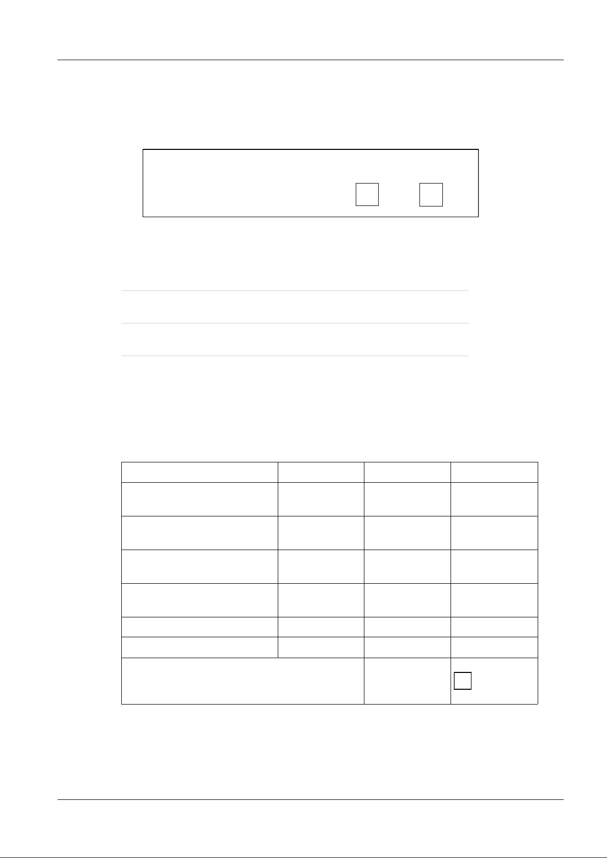
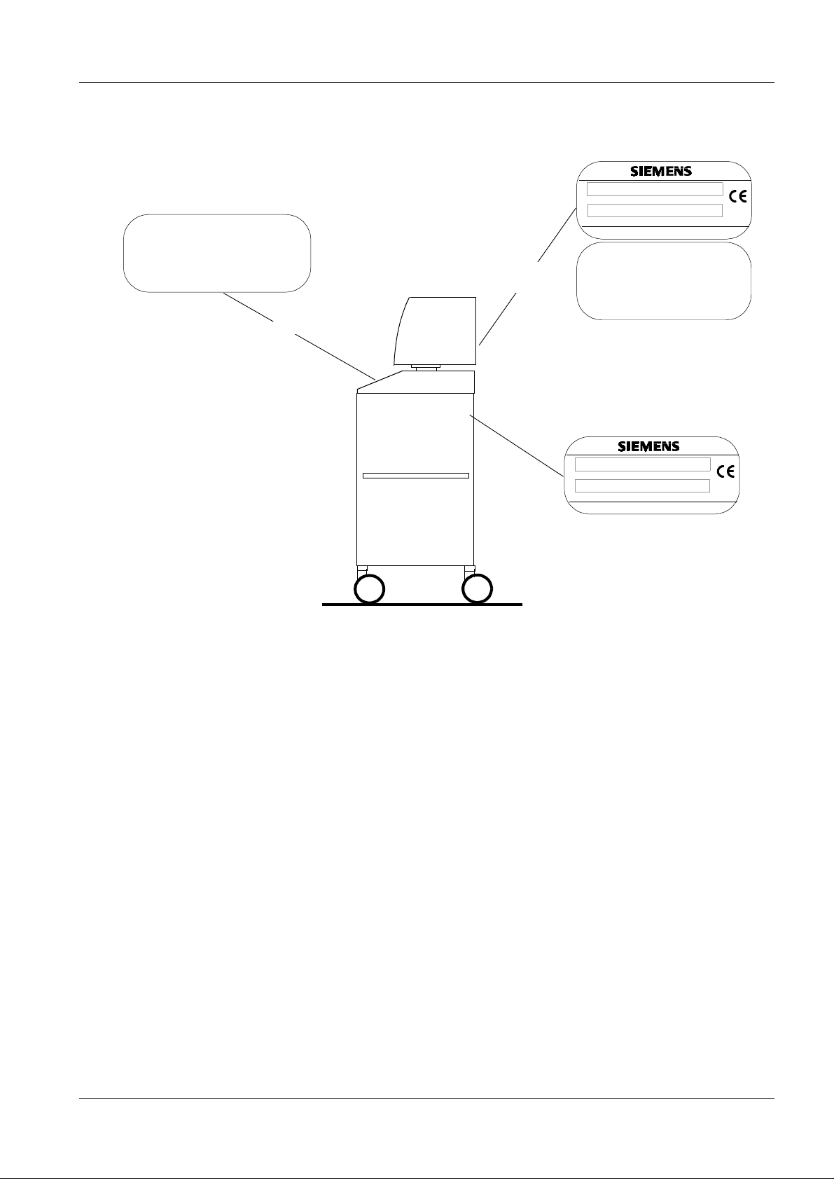
2 Checking the DHHS and Identification Labels 2
Confirm that the certificat ion labels as well as serial number and model number labels are
legible. The illustrati on shows the location of the labels.
If labels are required, contact the Regulatory Affairs department in Iselin, N.J.
Component certified Model No. Serial No. Date
SIREMOBIL Compact
X-ray control
Beam Limiting device
BLD
Cassette holder
(if present)
SIREPHOS Compact
Tube housing assembly
Image Intensifier
Television receiver
Warning label present and legible YES
Siemens AG RXR2-130.101.02 Page 1 of 4 SIREMOBIL Compact
Medical Engineering Rev. 02 08.97 TD SP 1
Page 8
2 - 2 Visual checks
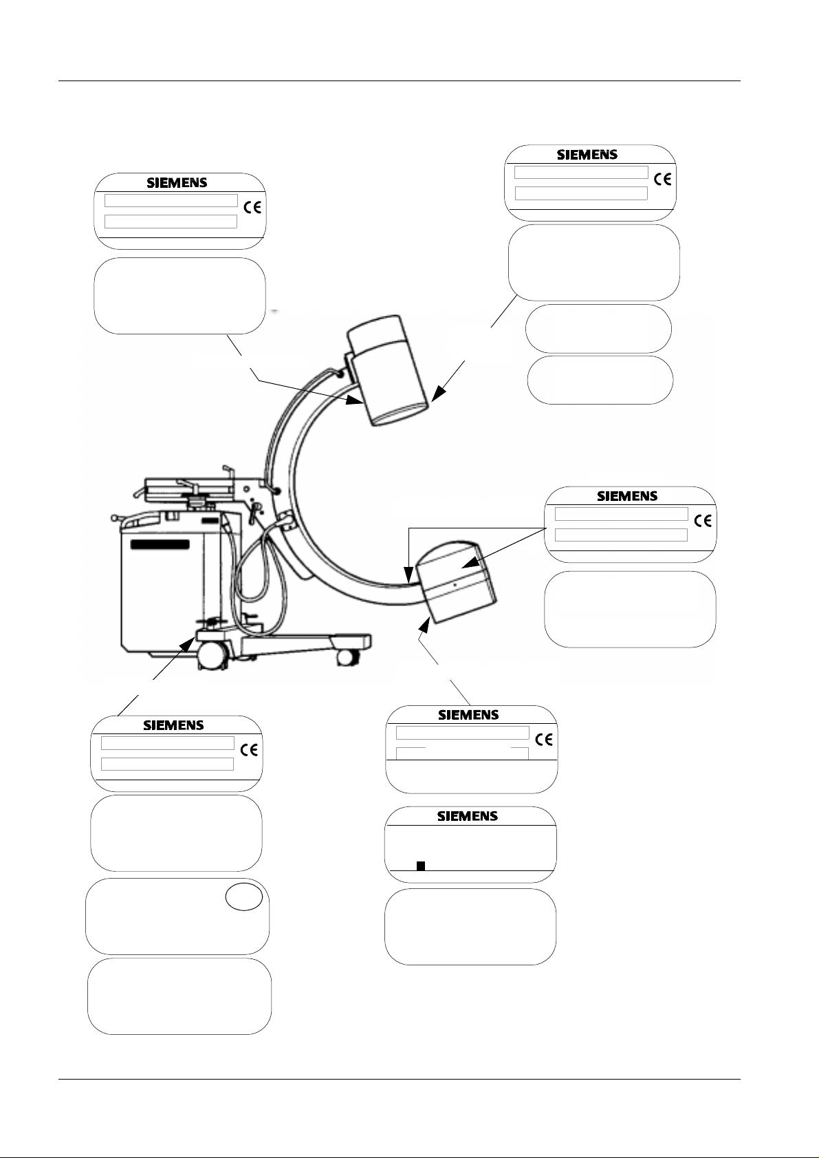
2.1 Location of the DHHS and Identification Labels 2
Model Nr.
Model Nr.
Serien Nr.
Made in Germany
This product complies with DHHSregulations
21 CFR Subchapter J, applicable at date of
manufacture.
Manufactured:
Siemens Aktiengesellschaft
Wittelsbacherplatz 2, D - 8 München 2
Germany
Image intensifier
cassette
holder
Serien Nr.
Made in Germany
This product complies with DHHSregulations
21 CFR Subchapter J, applicable at date of
manufacture.
Manufactured:
Siemens Aktiengesellschaft
Wittelsbacherplatz 2, D - 8 München 2
Germany
24 x 30 cm
10 x 12 ins.
Safety
instructions
X-Ray control
Model Nr.
Serien N r.
X-Ray Equipment
Classified by
Underwriters Laboratories Inc.
with Respect to Electrical Shock, Fire
and Mechanical Hazards Only.
Sach Nr.
ES 01 02 03 04 05 06 07
08 09 10 11 12 13 14 15
Made in Germany
This product complies with DHHSregulations
21 CFR Subchapter J, applicable at date of
manufacture.
Manufactured:
Siemens Aktiengesellschaft
Wittelsbacherplatz 2, D - 8 München 2
Germany
U
245 B
L
Beam limiting device
Model Nr.
Serien Nr.
*
Made in Germany
This product complies with DHHSregulations
21 CFR Subchapter J, applicable at date of
manufacture.
Manufactured:
Siemens Aktiengesellschaft
Wittelsbacherplatz 2, D - 8 München 2
Germany
Tube Housing assembly
SIREPHOS 110 kV / 5 mA
Model Nr.
11 73 355 X 1988
Serien Nr.
Inherent filtration
added filtration
Röhre/Tube SR 110
Model Nr.
Serien Nr.
This product complies with DHHSregulations
21 CFR Subchapter J, applicable at date of
manufacture.
Manufactured:
Wittelsbacherplatz 2, D 8 München 2
01001
Made in Germany
88 55 199 V 1036
0.6 IEC 336/82
Made in Germany
Siemens Aktiengesellschaft
S01
S06
Germany
**
* Label is not accessible to view.
A duplicate label is visible in the position shown
** minimum filtration: 3.0 mm Al
SIREMOBIL Compact RXR2-130.101.02 Page 2 of 4 Siemens AG
Rev. 02 08.97 TD SP 1 Medical Engineering
Page 9
Visual checks 2 - 3
Model Nr.
WARNING:
This X-Ray Unit may be dangerous to
Patient and Operator unless safe
Exposure factors and Operating
Instructions are observed:
Monitor cart
Television
Receiver
Serien N r.
Model Nr.
Serien Nr.
Made in Germany
This product complies with DHHSregulations
21 CFR Subchapter J, applicable at date of
manufacture.
Manufactured:
Siemens Aktiengesellschaft
Wittelsbacherplatz 2, D - 8 München 2
Germany
Made in Germany
Siemens AG RXR2-130.101.02 Page 3 of 4 SIREMOBIL Compact
Medical Engineering Rev. 02 08.97 TD SP 1
Page 10

2 - 4 Visual checks
This page intentionally left blank.
SIREMOBIL Compact RXR2-130.101.02 Page 4 of 4 Siemens AG
Rev. 02 08.97 TD SP 1 Medical Engineering
Page 11

Checking the function blocks and displays 3
1 Checking the ”deadman” switch function 3
1.1 Exposure 3
An exposure value is set at the control console.
- Activate the exposure with the exp osure switch and end it immediately by rel easing
the switch.
The exposure must end immediately.
1.2 Fluoroscopy 3
Activate fluoroscopy for a short time and release the fluoroscopy switch.
Fluoroscopy must stop immediately.
a) with the fluoroscopic switch at the control console
b) with the foot switch
3 - 1
Deadman’s switch is functi oning YES NO
2 Radiation indicators 3
Check that the radiation indicators at the control console and on the monitor cart are visible during radiation and that an audible (whistl ing) signal is sounded after exposure
release for about 1.5 seconds.
Radiation indicators are functioning YES NO
Siemens AG RXR2-130.101.02 Page 1 of 2 SIREMOBIL Compact
Medical Eng ineering Rev. 01 11.96 TD SP 1
Page 12

3 - 2 Checking the function blocks and displays
3 Fluoroscopy timer 3
1. Ensure that the people present are not subj ect to radiation hazard during the t ests
described below.
2. Set the manual fluoroscopy volta ge to the lowest possible kV value .
Close the Iris diaphragm, cover the t ube assembly with a lead apron.
3. Switch on fluoroscopy.
4. Check that the acoustic signal s ounds after a total fluoroscopy time of 4.5 minutes
has elapsed.
5. Reset the buzzer by pressing the button under the symbol in the display.
Fluoroscopy timer functioning correctly YES NO
4 Indication of X-ray tube potential and current 3
Confirm that tube potential and current are continuously indicated during fluoroscopy.
Indicators fu n ctioning YES NO
5 Minimum source to skin distance 3
Confirm that a spacer limiting the source to skin distance (SSD) to 30 cm is present.
Spacer present YES NO
SIREMOBIL Compact RXR2-130.101.02 Page 2 of 2 Siemens AG
Rev. 01 11.96 TD SP 1 Medical Engineering
Page 13

Function tests 4
1 Checking the accuracy of the tube voltage 4
The actual kV value must agree with the indicated value within the limits stated by
4 - 1
Siemens (max. deviation
nected to a power supply corresponding to Siemens specifications.
Tools: PTW-Nomex
Test procedure:
Refer to the information on the Nomex in the operating instructions
Connect the Nomex.
Remove the single-tank cap at the SIREPHOS after removing the two screws.
Select full image intensifier format and open the collimator fully.
Place the measuring detector on the diaphragm.
Set the following values in the operating field and check
Operating mode Indicated Measured Tolerance
Fluoroscopy 70 kV 63 kV to 77 kV
Fluoroscopy 101 kV 91 kV to 110kV
Fluoroscopy 110 kV 100 kV to 120 kV
Radiography 102 kV 92 kV to 110kV
&10 % for the Siremobil Compact), if the X-ray system is con-
2 Reproducibility 4
The coefficient of variation must not exceed 0. 05 when the X-ray system is c onnected to a
power supply as specified by Siemens.
The technique factors shoul d be adjus ted to alt ernate sett ings and rese t to t he test set ting
after each measurement.
2.1 Measurement set-up 4
Place the dosimeter in the center of the X-ray beam.
Before each new dose measurement, make sure that the indicator is reset to zero.
Siemens AG RXR2-130.101.02 Page 1 of 10 SIREMOBIL Compact
Medical Engineering Rev. 02 12.96 TD SP 1
Page 14

4 - 2 Function tests
1
2.2 Calculations 4
Variation coeffic ient C
For n individual measurements, the coefficient of variation C amounts to:
n
s
C = =
x
x
Σ
i = 1
(xi - x)
n -1
s = calculated standard deviation
= mean value of all individual measurements
x
= measured value of the ith measurements.
x
i
1. To obtain the average x, the 4dose values are added and the sum is divided by 3.
2. T o obtai n the difference, the average value is subtracted from each indi vidual
measured value and entered into the column prov ided
1/2
2
Measurement Radiation Exposure (xi ) Average ( ) = Difference*
x
1
2
3
4
* Disregard the sign if negative numbers are obtained.
Square the differences
2
Measurement Square of th e difference (x
- )
i
x
1
2
3
4
3. Add the 4results:
Σ ....................:
4. Divide the sum by 3: ...............
5. Obtain the square root of the ne w result: Square root S: .......... ........
6. Divide the square root S by the average value x determined in step 1:
S
Coefficient of variation C =
x
SIREMOBIL Compact RXR2-130.101.02 Page 2 of 10 Siemens AG
Rev. 02 12.96 TD SP 1 Medical Engineering
C = . . . . . . . . . . . . . . . (must be
≤ 0.05)
Page 15

Function tests 4 - 3
3 Entrance exposure rate 4
The legal maximum entrance exposure rate is 87 mGy/min (10 R/min).
For safety reasons, the value has been fixed at < 78 mGy/min (9 R/min) at the factory.
The entrance exposure rate is to be checked by means of a dose rate meter.
In the measurement setup shown, the maximum adjustable values 110 kV and 5 mA yield
an input dose rate of approx. 87mGy/min (10 R/min).
Measurement set-up
Image intensifier
2,1
cm
Fig. 1
30 cm
89,7 cm
Input screen
Ionization
chamber
Focal spot
Position the measurement detector of the dosimeter as shown in the diagram.
Press the " ” button at the operating console.
Select 110 kV. Select full I.I. format, open the collimator to max. aperture, switch fluoroscopy ”ON”. Measure the dose and record.
Siemens AG RXR2-130.101.02 Page 3 of 10 SIREMOBIL Compact
Medical Engineering Rev. 02 12.96 TD SP 1
Page 16

4 - 4 Function tests
4 Checking the central beam 4
REGULATION - Means must be available whereby the radiation field can be centered
in relation to the radiation receiver within a tolerance of less than 2 % of the SID.
4.1 Position of central beam in relation to the I.I. input 4
The check is made at the TV monitor.
Determine the central point at the I.I. input. Use adhesive tape to attach center cross
(with lead ruler).
Open the slot collimator, adjust the iris diaphragm to an opening of about 15 cm.
Perform the test in the C-arm position shown.
Fig. 2
Basic position
C-arm to the left
(top view)
C-arm to the right
(top view)
SIREMOBIL Compact RXR2-130.101.02 Page 4 of 10 Siemens AG
Rev. 02 12.96 TD SP 1 Medical Engineering
Page 17

Function tests 4 - 5
x2 + y
2
A = mid-point I.I. input
B = middle of the radiation
field
∆ = deviation of A to B
x = deviation in the x-axis
y
y = deviation in the y-axis
Fig. 3
Work sequence:
1. Select full size (no zoom).
2. Adjust the Iris diaphragm to an opening of about 15 cm.
3. Adjust C-arm (see Fig. 2).
4. Read the evaluation at the TV Monitor ( Fig. 3).
(Use stored image if available).
x
A
B
∆
5. Switch on fluoroscopy
6. Calculate the deviat ion
:
7. Test result (see also Fig. 3):
Average deviation permissible* Average deviation actual
Basic position = must be 17 mm
(2% of the SID)
C-arm to the left = must be 17 mm
(2% of the SID)
C-arm to the right = must be 17 mm
(2% of the SID)
...................... mm
...................... mm
...................... mm
Siemens AG RXR2-130.101.02 Page 5 of 10 SIREMOBIL Compact
Medical Engineering Rev. 02 12.96 TD SP 1
Page 18

4 - 6 Function tests
5 Check the I.I. format 4
TV image
During fluoro, neither the length nor the width of the
radiation field in t he plane of the image receptor may
exceed that of the visible area of the imag e receptor
by more than 3 % of the SID (focus - I.I. distance).
The sum of the longitudinal deviation X and the
Blades, iris diaphragm
Fig. 4
Work sequence:
1. Select the full I.I. input for mat.
width deviation Y shall be no greater t han 4 % of the
2. Set the iris diaphragm to max. apertur e
3. Switch on fluoroscopy
If all eight blades of the ir is diaphragm are still visible at t he edge of the TV monitor
(Fig. 4), no further test s are necessary.
4. Select zoom format (check as in it em 3)..
I.I. format in order YES NO
Zoom format in order YES NO
6 Check the smallest field size 4
The smallest field size should be max. 5 cm x 5 cm at the I.I. input.
The check is made at the TV monitor.
1. Select full I.I. view for mat.
2. Close the iris diaphragm and selec t full I.I. view format.
3. Attach a center cross with lead ru ler to the center of the I.I. input screen.
4. Switch on fluoroscopy.
5. Read the size of the X iris on the monitor.
Smallest field size at the I.I. input: ........ cm x ........ cm
SIREMOBIL Compact RXR2-130.101.02 Page 6 of 10 Siemens AG
Rev. 02 12.96 TD SP 1 Medical Engineering
Page 19

Function tests 4 - 7
7 Cassette format 4
(Only applicable if cassette holder present)
If no cassette is inserted, continuous fluoroscopy is selected.
Exposure release need not be blocked.
Neither the length nor the width of the X-ray field in t he plane of the image receptor shall
differ from the c orresponding dimensions of the selected portion of the image receptor by
more than 3 percent of the SID when adjusted for full coverage of the sel ected portion of
the image receptor. The sum (disregarding the sign) of the length and width deviations
may not exceed 4 % of the SID.
The cassette format is limited by means of the rectangular diaphragm.
7.1 Cassette to radiation field 4
Film 35 cm x 35 cm
Fig. 5
∆B
∆D
∆A
Film(cassette 24 cm x 30 cm
Rad. field
Work sequence:
1. Move the C-arm into the basic position.
2. Attach the cassette holder to t he I.I.
3. Load a 24” x 30” cassette with fi lm and insert into the cassett e holder.
4. Place a 35 cm x 35 cm film in an opaque envelope and attach t he envelope to the
center of the film cassette with adhesive tape.
5. In addition, place three washers on t he opaque envelope and attach them with
adhesive tape.
All three washers must be located wi thin the 24 cm x 30 cm cassette.
∆C
6. Expose both films.
7. Develop the films.
8. Place the films one on top of the other.
9. Calculate the deviat ions.
10. Enter the deviations in the corres ponding table.
11. Repeat items 3 through 8 for the C-arm "lef t" and the C-arm "right" position ( Fig.7).
Siemens AG RXR2-130.101.02 Page 7 of 10 SIREMOBIL Compact
Medical Engineering Rev. 02 12.96 TD SP 1
Page 20

4 - 8 Function tests
SID’ (source film distance) 85.9 cm
C-arm to the right,
Tube assembly at stop
Basic position
Fig. 6
C-arm to the left,
Tube assembly at stop
(top view)
C-arm basic position
(must be
Shading ∆ A ......... + ∆ C .......... = .......... mm
∆ B ......... + ∆ D .......... = .......... mm
∆ A ......... + ∆ B ......... + ∆ C .......... + ∆ D ....... = ........ mm (must be < 34 mm)
C-arm to the left, tube assembly at stop
Shading
∆ A ......... + ∆ B ......... + ∆ C .......... + ∆ D ....... = ........ mm (must be < 34 mm)
C-arm to the right, tube assembly at stop
Shading
∆ A ......... + ∆ C .......... = .......... mm
∆ B ......... + ∆ D .......... = .......... mm
∆ A ......... + ∆ C .......... = .......... mm
∆ B ......... + ∆ D .......... = .......... mm
(3% of the SID)
(must be
(3% of the SID)
(4% of the SID)
(must be
(3% of the SID)
(must be
(3% of the SID)
(4% of the SID)
(must be
(3% of the SID)
(must be
(3% of the SID)
< 25 mm)
< 25 mm)
< 25 mm)
< 25 mm)
< 25 mm)
< 25 mm)
∆ A ......... + ∆ B ......... + ∆ C .......... + ∆ D ....... = ........ mm (must be < 34 mm)
(4% of the SID)
If the deviations are within the given tolerance, no additional tests are necessary.
SIREMOBIL Compact RXR2-130.101.02 Page 8 of 10 Siemens AG
Rev. 02 12.96 TD SP 1 Medical Engineering
Page 21

Function tests 4 - 9
7.2 Center cassette to radiation field 4
Film 35 cm x 35 cm
Rad. field
∆A
Film (cassett e 24 cm x 30 cm)
Fig. 7
Work sequence:
1. Use the film pairs already exposed (C-arm in basic position, C-ar m to the right
and C-arm to the left) to evaluate the cente r deviation.
2. Place the film pairs one on top of the other.
3. Mark the geometric center of the 24 cm x 30 cm f ilm.
4. Mark the geometric center of the ra diation field.
5. Calculate the deviat ion.
C-arm basic position:
∆ = .......... mm (must be < 17mm), (2% of the SID)
C-arm to the left, tube assembly at stop
∆ = .......... mm (must be < 17mm), (2% of the SID)
C-arm to the right, tube assembly at stop
∆ = .......... mm (must be < 17mm), (2% of the SID)
If the deviations are within the given tole rance, no additional tests are necessary.
Siemens AG RXR2-130.101.02 Page 9 of 10 SIREMOBIL Compact
Medical Engineering Rev. 02 12.96 TD SP 1
Page 22

4 - 10 Function tests
This page intentionally left blank.
SIREMOBIL Compact RXR2-130.101.02 Page 10 of 10 Siemens AG
Rev. 02 12.96 TD SP 1 Medical Engineering
Page 23

Technical Data 5
Technical data for DHHS components 5
In accordance with Federal Radiation Performance
Standards 21 CFR Subchapter J Paragraph 1020.30 (h)
X-Ray Controls and Generators 5
5 - 1
Nominal
line voltage:
100 V ± 10% 12% 28 A
120 V ± 10% 8% 24 A
127 V ± 10% 7% 22 A
230 V ± 10% 5% 12 A
240 V ± 10% 5% 12 A
Technique factors for maximum line current:
110 kV
tube voltage, 13 mA tube current
p
Rated line
voltage:
Line-voltageregulation:
Maximum line
current:
Generator ratings: 5
Fluoroscopy: 110 kVp maximum voltage, 5 mA maximum current
Radiography: Duty cycle: 1:60
- 40 kV/20 mA
- 110 kV/13 mA
Maximum deviations 5
Radiography
Tube voltage: ± 10 %
accuracy of mAs-product: ± 10 % ± 0.2 mAs
Fluoroscopy
Tube voltage: ± 10 %
Tube current: ± 8 % ± 0.1 mA
Fluoroscopy timer: 0 to 5 min. tolerance 1 digit (6 sec)
Basic measurement used
Peak tube potential: PTW-Nomex (2 filter method)
Tube current: by using RMS-multimeter
mAs-product: PTW-Nomex
Siemens AG RXR2-130.101.02 Page 1 of 2 SIREMOBIL Compact
Medical Eng ineering Rev. 02 11.96 TD SP 1
Page 24

5 - 2 Technical Data
Tube Housing Assemblies 5
Maximum rated peak tube potential: 110 kV
p
Leakage technique factors: 110 kVp/5.0 mA
Minimum filtration permanently in the useful beam: 3 mm Al equivalent
obtained at: 80 kV
p
Cooling curves
Tube housing cooling curve: See Operator‘s Manual
Tube rating charts: See Operator‘s Manual
Definitions of the measurement bases of technique factors 5
Exposure time tube current product:
Measured in the mA-measuring pins D1.X39-D1. X40 (x97 opened) in the tube current circuit near ground with an mAs-meter (PTW- Nomex or equivalent).
Peak tube potential:
Measurement of kVp at radiography and at fluoroscopy, using PTW-Nomex (2 filter
method).
Tube current:
As measured in the mA-measuring pins D1.X39- D1.X40 (x97 opened) in the tube current
circuit near ground with an mA-meter (FLUKE 8060 A or equivalent), minus the current
flowing through the built-in high-voltage divider of 0.0025 mA/kV
.
p
SIREMOBIL Compact RXR2-130.101.02 Page 2 of 2 Siemens AG
Rev. 02 11.96 TD SP 1 Medical Engineering
Page 25

Final steps 6
Final visual and function checks 6
• After completion of all required operations and c hecks, perform a visual and function
check.
For example, ensure that
- moving parts are freely moving
- there is no danger of collision for movi ng parts
- safety distances are maintain ed
- all parts are p roperly secured
- there is no perceptible damage, et c.
6 - 1
Siemens AG RXR2-130.101.02 Page 1 of 2 SIREMOBIL Compact
Medical Eng ineering Rev. 01 11.96 TD SP 1
Page 26

6 - 2 Final steps
This page intentionally left blank.
SIREMOBIL Compact RXR2-130.101.02 Page 2 of 2 Siemens AG
Rev. 01 11.96 TD SP 1 Medical Engineering
Page 27

Changes to previous version 7
Chapter 0: Cover sheet was adjusted,
Revision level was adjusted accordngly.
Chapter 2: page 2: Part No. of the "Tube Housing assembly" changed
Chapter 7: Content adapted
7 - 1
TD SP 2 / Arnold
TD SP 1 / Schlee
SMS Iselin / O’Donnell
Siemens AG RXR2-130.101.02 Page 1 of 2 SIREMOBIL Compact
Medical Engineering Rev. 02 08.97 TD SP 1
Page 28

7 - 2 Changes to previous version
This page intentionally left blank.
SIREMOBIL Compact RXR2-130.101.02 Page 2 of 2 Siemens AG
Rev. 02 08.97 TD SP 1 Medical Engineering
 Loading...