

Siemens SIREC D200 Quick Start Manual
A5E01040182-01; 43-TV-25-40 Iss.1 GLO Oct 06 UK 1
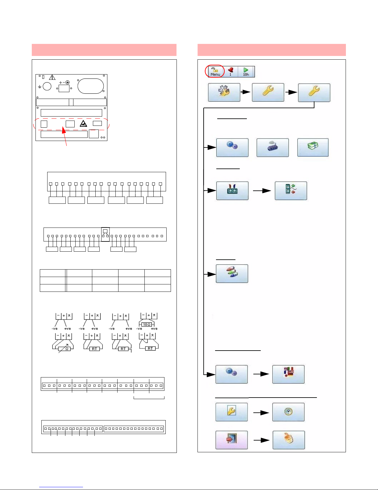
1. Connections
1) Earth/ground
2) 24VDC Inst. power (option)
3) AC supply 100-250VAC
4) CJC Connector (option)
5) 24V TXP Supply (option)
6) RS485 port (option)
7) USB host (option)
8) Ethernet connection (std)
D200 rear panel
Analogue Input board - 6 ch expansion (option). D200 = Slot B
1 2 3 4 5 6 7 8 9
CJC
- +
*
13 14 15 16 17 1810 11 12
- +
*
- +
*
- +
*
- +
*
- +
*
Relay Alarm - 4 or 8 channel (option). D200 = Slot G
1 2 3 4 5 6 7 8 9
NO C NO C NO C NO C NO C NO C NO C NO C
10 11 12 13 14 15 16
Digital Input/Output - 8 channel (option). D200 = Slot G
Key: NO = Normally Open, C = Common, NC = Normally Closed,
Ohms 3 wire R/T 4 wire R/T 2 wire R/T
mV, V T/C Passive T/C Active Current
(Slot B only)
Slot B
Slot G
Slot A
ETHERNET
USB
RS485
24Vdc TX
5
6
7
4 (CH9 - 14)
3
2
1
8
24V TX Power Supply 2-way conn (5), RS485 Modbus port (6)
and USB port (7) are all on the Comms option card
Analogue Input - 3 or 6 channel. D200 = Slot A
1 2 3 4 5 6 7 8 9 10 11 12
13 14 15 16 17 18
- +*- +*- +*- +*- +*- +
*
Card 3 CH. 6 CH. 9 CH. 12 CH.
A 1-3 1-6 1-3 1-6
B 9-14 9-14
CH1 CH2 CH3 CH4 CH5 CH6
CH9 CH10 CH11 CH12 CH13 CH14
1 2 3 4 5 6 7 8 9
NC C NO NC C NO NC C NO NC C NO NC C NO NC C NO NC C NO NC C NO
10 11 12 13 14 15 16 17 18 19 20 21 22 23 24
Input across NO, C
(CH1-3/CH1-6)
2. Setup Menu
Inputs
All Analogue Inputs default to 12V
Select Input channel
• Setup input Type. V, A, Ohms, RT, TC
• Select Sample Rate
• Select Range / RT / TC Type
Use Back button to return to Setup Menu
Pens
By default Pen 1 displays
Analogue Input 1, Pen 2
displays Analogue 2 etc.
Localization
Set Date
and Time
Select the Menu button
from the Process Screen
Configure
Setup
Edit
Field IO
Analogue In
Pens
General
Finish Commit
Localisation
Back
Settings (Main Menu > Configure)
Settings
Set Time
Settings for Language and Time Zones, etc.
General
Credits
Factory
Options
Select Options in Credits menu, tick firmware
options to enable. Go to Finish and Commit
Select Pen
• Setup Scale
• Set Alarms, if required
• Setup Logging (required to Log and
Save data in memory)
Use Back button to return to Setup Menu
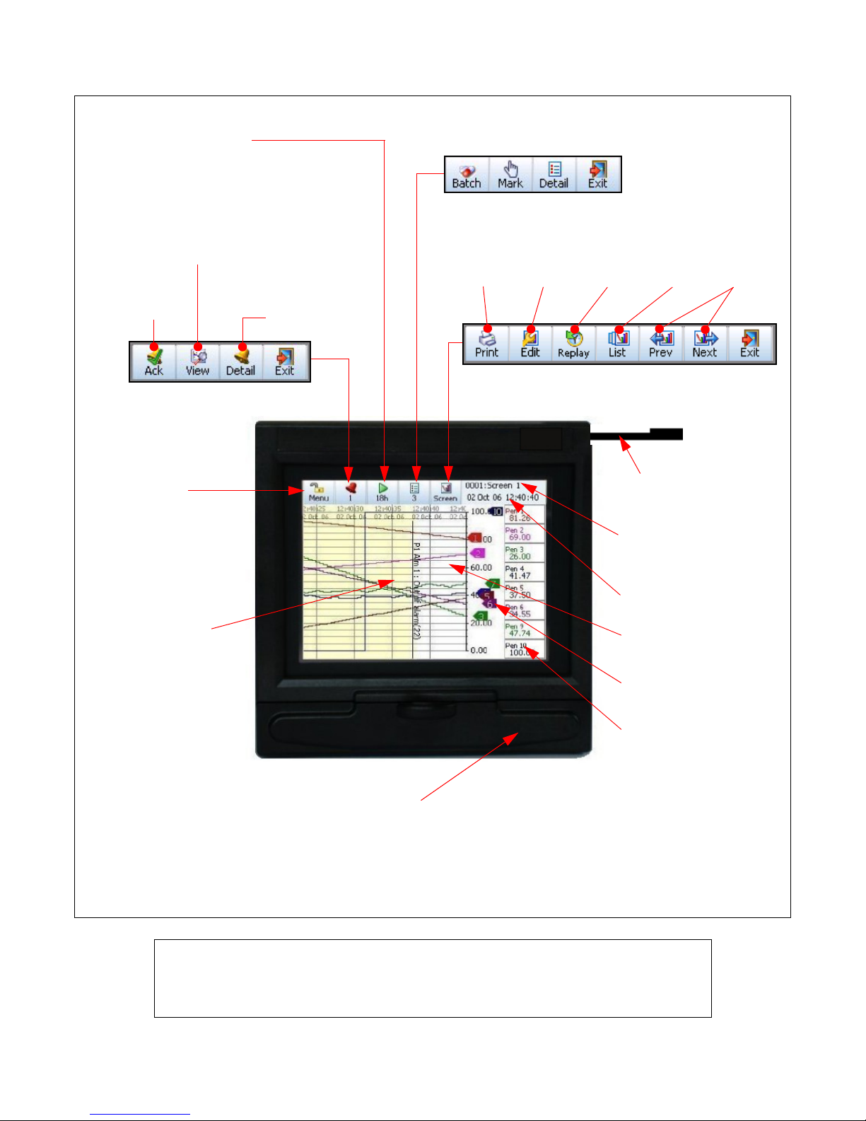
Quick Start Guide - SIREC D200 Display Recorder
s
2 A5E01040182-01; 43-TV-25-40 Iss.1 GLO Oct 06 UK
Recording menu allows:
• stop/start recording
• immediate download
of recorded data
Message Count menu allows quick access to
Batch, User Mark on chart, and Messages Detail
Acknowledge
all Alarms
Alarm Status/
Configure
Individual Alarm
Acknowledge
Enter recorder
Setup menu
Recorder ID No. & Name
alternates with the
Screen Name
Time and Date
Chart Area
Realtime Pen Pointers
Pen Digital Read-out
(DPM)
View Alarms
Touch the screen
to activate a short
cut to Settings
such as change
the chart speed
Print Modify Replay List of View
process screen chart available available
screen layouts history screens screens
Stylus (for use with
the touch screen)
USB Host Port (behind the
door). Connect Keyboard/
Mouse for set up or USB
memory for data transfer
NOTICE
For detailed information on all recorder settings and configuration parameters
please refer to the SIREC D200, D300, D400 Manual.
 Loading...