

Siemens siprotec SJ62, siprotec SJ63, siprotec SJ64 User Manual

Preface
SIPROTEC
Multi-Functional Protective
Relay with Local Control
7SJ62/63/64
V4.6
7SJ63
V4.7
Introduction
Functions
Mounting and Commissioning
Technical Data
Appendix
Literature
Glossary
Index
1
2
3
4
A
Manual
C53000-G1140-C147-A

Disclaimer of liability
We have checked the contents of this manual against the hardware and software described. However, deviations from the description cannot be completely ruled out, so that no liability can
be accepted for any errors or omissions contained in the information given.
The information given in this document is reviewed regularly and
any necessary corrections will be included in subsequent editions. We appreciate any suggested improvements.
We reserve the right to make technical improvements without
notice.
Document version 04.64.01
Edition 07.2015
Copyright
Copyright © Siemens AG 2015. All rights reserved.
Dissemination or reproduction of this document, or evaluation
and communication of its contents, is not authorized except
where expressly permitted. Violations are liable for damages. All
rights reserved, particularly for the purposes of patent application
or trademark registration.
Registered Trademarks
SIPROTEC, SINAUT, SICAM and DIGSI are registered trademarks of Siemens AG. Other designations in this manual might
be trademarks whose use by third parties for their own purposes
would infringe the rights of the owner.
SIPROTEC 4, 7SJ62/63/64 Handbuch
C53000-G1140-C147-A, Edition 07.2015

SIPROTEC 4, 7SJ62/63/64 Handbuch
C53000-G1140-C147-A, Edition 07.2015
3
Preface
Purpose of this Manual
This manual describes the functions, operation, installation, and commissio ning of the
device 7SJ62/63/64. In particular, one will find:
• Information on the Device Configuration and a description of the device functions
and setting options → Chapter 2;
• Instructions for mounting and commissioning → Chapter 3;
• List of technical data → Chapter 4;
• As well as a compilation of the most significant data for experienced users in Appendix A.
For general information on operation and configuration of SIPROTEC 4 devices,
please refer to the SIPROTEC System Description /1/.
Target Audience Protection engineers, commissioning engineers, personnel concerned with adjust-
ment, checking, and service of selective protective equipment, automatic and control
facilities, and personnel of electrical facilities and power plants.
Applicability of this Manual
This manual is valid for: SIPROTEC 4 Multi-Functional Protective Relay with Local
Control 7SJ62/63/64 firmware version V4.6 anf for 7SJ63 firmware version V4.7.
The functionality of the devices 7SJ63 V4.6 and V4.7 is identical.
7SJ63 firmware versions V4.7 are actual maintenance versions.
Indication of Conformity
This product complies with the directive of the Council of the European Communities on the approximation of the laws of the Member States relating to electromagnetic compatibility (EMC Council Directive 89/336/EEC) and concerning electrical equipment for use within specified voltage limits (Low-voltage directive 73/23
EEC).
This conformity has been proved by tests performed according to Article 10 of the
Council Directive in agreement with the generic standards EN 61000-6-2 and
EN 61000-6-4 (for EMC directive) and with the standard EN 60255-6 (for Low
Voltage Directive) by Siemens. AG.
This device is designed and manufactured for application in industrial environment.
The product conforms with the international standards of IEC 60255 and the
German standard VDE 0435.
SIPROTEC 4, 7SJ62/63/64 Handbuch
C53000-G1140-C147-A, Edition 07.2015
4

Preface
Further standards IEEE Std C37.90-*
Additional Support Should further information on the System SIPROTEC 4 b e desired or should particular
problems arise which are not covered sufficiently for the purchaser's purpose, the
matter should be referred to the local Siemens representative.
Training Courses Individual course offerings may be found in our Training Catalogue, or questions may
be directed to our training centre in Nuremberg.
Instructions and
Warnings
The warnings and notes contained in this man ual serve for your own safety and fo r
an appropriate lifetime of the device. Please observe them!
The following indicators and standard definitions are used:
DANGER
indicates that death, severe personal injury or substantial property damage will
result if proper precautions are not taken.
Warning
indicates that death, severe personal injury or substantial property damage can
result if proper precautions are not taken.
Caution
indicates that minor personal injury or property damage can result if pr oper precautions are not taken. This pa rticularly applies to damage on or in the device itself and
consequential damage thereof.
Note
indicates information about the device or respective part of the instruction manual
which is essential to highlight.
5
SIPROTEC 4, 7SJ62/63/64 Handbuch
C53000-G1140-C147-A, Edition 07.2015

WARNING!
When operating an electrical device, certain p arts of the device inevitably have dangerous voltages.
Failure to observe these precautions can result in fat ality , personal injury , or extensive
material damage.
Only qualified personnel shall work on and around this equipment. It must be thoroughly familiar with all warnings and safety notices of this manual as well as with the
applicable safety regulations.
The successful and safe operation of this device is dependent on proper handling, installation, operation, and maintenance by qu alified personnel under observance of all
warnings and hints contained in this manual. In particular the general erection and
safety regulations (e.g. IEC, DIN, VDE, EN or other national and international standards) regarding the correct use of hoisting gear must be observed.
Definition QUALIFIED PERSONNEL
For the purpose of this instruction manual and pro duct labels, a qualified person is
one who is familiar with the installation, construction and operation of the equipment
and the hazards involved. In addition, he has the following qualifications:
• Is trained and authorized to energize, de-energize, clear, ground and tag circuits
and equipment in accordance with established safety practices.
• Is trained in the proper care and use of protective equipment in accordance with
established safety practices.
• Is trained in rendering first aid.
Preface
Typographic and
Graphical Conventions
To designate terms which refer in the tex t to infor matio n of the device or for the
device, the following fonts are used:
Parameter names
Designators of configuration or function parameters which may appear word-forword in the display of the device or on the screen of a personal computer (with operation software DIGSI), are marked in bold letters of a monospace type style. This
also applies to header bars for selection menus.
1234A
Parameter addresses have the same character style as p arameter name s. Parameter addresses contain the su ffix A in the overview t ables if the p arameter ca n only
be set in DIGSI via the option Display additional settings.
Parameter Conditions
possible settings of text parameters, which may appear word-for-word in the display
of the device or on the screen of a personal computer (with operation software
DIGSI), are additionally written in italics. This also applies to header bars for selection menus.
„Annunciations“
Designators for information, which may be output by the relay or requ ired from other
devices or from the switch gear , are marked in a monosp ace type style in quot ation
marks.
Deviations may be permitted in drawings and tables when the type of desig nator can
be obviously derived from the illustration.
SIPROTEC 4, 7SJ62/63/64 Handbuch
C53000-G1140-C147-A, Edition 07.2015
6
Preface
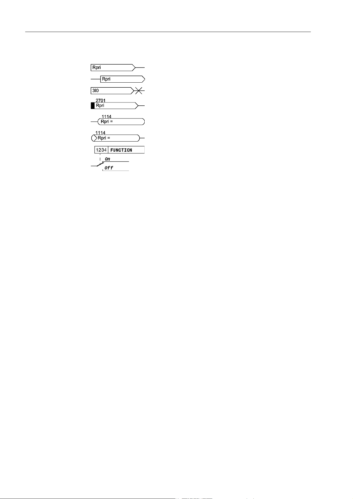
The following symbols are used in drawings:
Device-internal logical input signal
Device-internal logical output signal
Internal input signal of an analog quantity
External binary input signal with number (binary input, input
indication)
External binary output signal with number (device in dication)
External binary output signal with number (device ind ication)
used as input signal
Example of a parameter switch designated FUNCTION with
the address 1234 and the possible settings ON and OFF
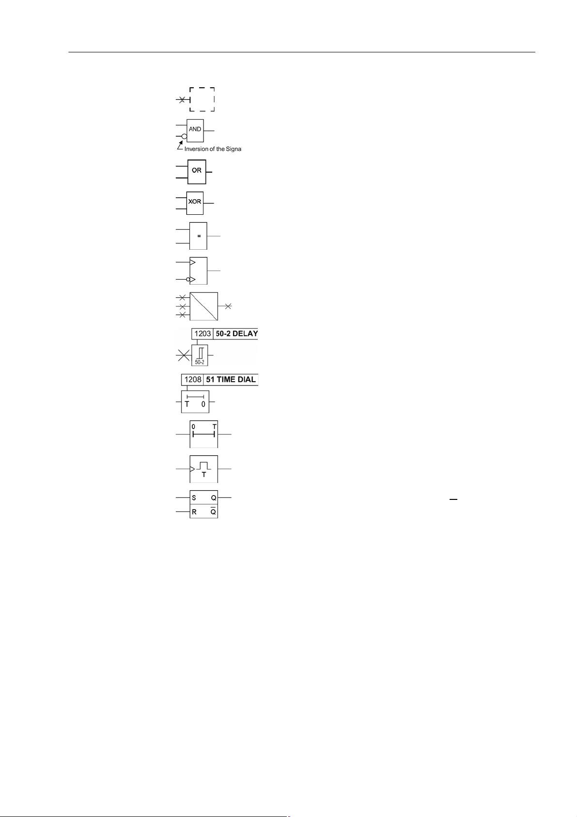
Besides these, graphical symbols are used according to IEC 60617-12 and IEC
60617-13 or symbols derived from these stand ards. Some of the most frequently used
are listed below:
7
SIPROTEC 4, 7SJ62/63/64 Handbuch
C53000-G1140-C147-A, Edition 07.2015
Preface
Input signal of an analog quantity
AND gate
OR gate
Exclusive–OR gate (antivalence): output is active, if only
one of the inputs is active
Equivalence: output is active, if both inputs are active or inactive at the same time
Dynamic inputs (edge–triggered) above with positive , below
with negative edge
Formation of one analog output signal from a number of
analog input signals
Limit stage with setting address and parameter designator
(name)
Timer (pickup delay T, example adjustable) with setting
address and parameter designator (name)
Timer (dropout delay T, example non-adjustable)
Dynamic triggered pulse timer T (monoflop)
Static memory (RS-flipflop) with setting input (S), resetting
input (R), output (Q) and inverted output (Q
)
■
SIPROTEC 4, 7SJ62/63/64 Handbuch
C53000-G1140-C147-A, Edition 07.2015
8

Preface
9
SIPROTEC 4, 7SJ62/63/64 Handbuch
C53000-G1140-C147-A, Edition 07.2015

Contents
1 Introduction. . . . . . . . . . . . . . . . . . . . . . . . . . . . . . . . . . . . . . . . . . . . . . . . . . . . . . . . . . . . . . . . . . . . 20
1.1 Overall Operation . . . . . . . . . . . . . . . . . . . . . . . . . . . . . . . . . . . . . . . . . . . . . . . . . . . . . . . . 21
1.2 Application Scope . . . . . . . . . . . . . . . . . . . . . . . . . . . . . . . . . . . . . . . . . . . . . . . . . . . . . . . . 25
1.3 Characteristics. . . . . . . . . . . . . . . . . . . . . . . . . . . . . . . . . . . . . . . . . . . . . . . . . . . . . . . . . . . 28
2 Functions. . . . . . . . . . . . . . . . . . . . . . . . . . . . . . . . . . . . . . . . . . . . . . . . . . . . . . . . . . . . . . . . . . . . . . 34
2.1 General . . . . . . . . . . . . . . . . . . . . . . . . . . . . . . . . . . . . . . . . . . . . . . . . . . . . . . . . . . . . . . . . 36
2.1.1 Functional Scope. . . . . . . . . . . . . . . . . . . . . . . . . . . . . . . . . . . . . . . . . . . . . . . . . . . . . . . . . 36
2.1.1.1 Description . . . . . . . . . . . . . . . . . . . . . . . . . . . . . . . . . . . . . . . . . . . . . . . . . . . . . . . . . . . . . 36
2.1.1.2 Setting Notes. . . . . . . . . . . . . . . . . . . . . . . . . . . . . . . . . . . . . . . . . . . . . . . . . . . . . . . . . . . . 36
2.1.1.3 Settings . . . . . . . . . . . . . . . . . . . . . . . . . . . . . . . . . . . . . . . . . . . . . . . . . . . . . . . . . . . . . . . . 38
2.1.2 Device, General Settings. . . . . . . . . . . . . . . . . . . . . . . . . . . . . . . . . . . . . . . . . . . . . . . . . . . 41
2.1.2.1 Description . . . . . . . . . . . . . . . . . . . . . . . . . . . . . . . . . . . . . . . . . . . . . . . . . . . . . . . . . . . . . 41
2.1.2.2 Setting Notes. . . . . . . . . . . . . . . . . . . . . . . . . . . . . . . . . . . . . . . . . . . . . . . . . . . . . . . . . . . . 41
2.1.2.3 Settings . . . . . . . . . . . . . . . . . . . . . . . . . . . . . . . . . . . . . . . . . . . . . . . . . . . . . . . . . . . . . . . . 42
2.1.2.4 Information List . . . . . . . . . . . . . . . . . . . . . . . . . . . . . . . . . . . . . . . . . . . . . . . . . . . . . . . . . . 42
2.1.3 Power System Data 1 . . . . . . . . . . . . . . . . . . . . . . . . . . . . . . . . . . . . . . . . . . . . . . . . . . . . . 44
2.1.3.1 Description . . . . . . . . . . . . . . . . . . . . . . . . . . . . . . . . . . . . . . . . . . . . . . . . . . . . . . . . . . . . . 44
2.1.3.2 Setting Notes. . . . . . . . . . . . . . . . . . . . . . . . . . . . . . . . . . . . . . . . . . . . . . . . . . . . . . . . . . . . 44
2.1.3.3 Settings . . . . . . . . . . . . . . . . . . . . . . . . . . . . . . . . . . . . . . . . . . . . . . . . . . . . . . . . . . . . . . . . 48
2.1.3.4 Information List . . . . . . . . . . . . . . . . . . . . . . . . . . . . . . . . . . . . . . . . . . . . . . . . . . . . . . . . . . 49
2.1.4 Oscillographic Fault Records. . . . . . . . . . . . . . . . . . . . . . . . . . . . . . . . . . . . . . . . . . . . . . . . 50
2.1.4.1 Description . . . . . . . . . . . . . . . . . . . . . . . . . . . . . . . . . . . . . . . . . . . . . . . . . . . . . . . . . . . . . 50
2.1.4.2 Setting Notes. . . . . . . . . . . . . . . . . . . . . . . . . . . . . . . . . . . . . . . . . . . . . . . . . . . . . . . . . . . . 50
2.1.4.3 Settings . . . . . . . . . . . . . . . . . . . . . . . . . . . . . . . . . . . . . . . . . . . . . . . . . . . . . . . . . . . . . . . . 51
2.1.4.4 Information List . . . . . . . . . . . . . . . . . . . . . . . . . . . . . . . . . . . . . . . . . . . . . . . . . . . . . . . . . . 51
2.1.5 Settings Groups. . . . . . . . . . . . . . . . . . . . . . . . . . . . . . . . . . . . . . . . . . . . . . . . . . . . . . . . . . 52
2.1.5.1 Description . . . . . . . . . . . . . . . . . . . . . . . . . . . . . . . . . . . . . . . . . . . . . . . . . . . . . . . . . . . . . 52
2.1.5.2 Setting Notes. . . . . . . . . . . . . . . . . . . . . . . . . . . . . . . . . . . . . . . . . . . . . . . . . . . . . . . . . . . . 52
2.1.5.3 Settings . . . . . . . . . . . . . . . . . . . . . . . . . . . . . . . . . . . . . . . . . . . . . . . . . . . . . . . . . . . . . . . . 53
2.1.5.4 Information List . . . . . . . . . . . . . . . . . . . . . . . . . . . . . . . . . . . . . . . . . . . . . . . . . . . . . . . . . . 53
2.1.6 Power System Data 2 . . . . . . . . . . . . . . . . . . . . . . . . . . . . . . . . . . . . . . . . . . . . . . . . . . . . . 54
2.1.6.1 Description . . . . . . . . . . . . . . . . . . . . . . . . . . . . . . . . . . . . . . . . . . . . . . . . . . . . . . . . . . . . . 54
2.1.6.2 Setting Notes. . . . . . . . . . . . . . . . . . . . . . . . . . . . . . . . . . . . . . . . . . . . . . . . . . . . . . . . . . . . 54
2.1.6.3 Settings . . . . . . . . . . . . . . . . . . . . . . . . . . . . . . . . . . . . . . . . . . . . . . . . . . . . . . . . . . . . . . . . 57
2.1.6.4 Information List . . . . . . . . . . . . . . . . . . . . . . . . . . . . . . . . . . . . . . . . . . . . . . . . . . . . . . . . . . 57
2.1.7 EN100-Module . . . . . . . . . . . . . . . . . . . . . . . . . . . . . . . . . . . . . . . . . . . . . . . . . . . . . . . . . . 58
2.1.7.1 Functional Description. . . . . . . . . . . . . . . . . . . . . . . . . . . . . . . . . . . . . . . . . . . . . . . . . . . . . 58
2.1.7.2 Setting Notes. . . . . . . . . . . . . . . . . . . . . . . . . . . . . . . . . . . . . . . . . . . . . . . . . . . . . . . . . . . . 58
2.1.7.3 Information List . . . . . . . . . . . . . . . . . . . . . . . . . . . . . . . . . . . . . . . . . . . . . . . . . . . . . . . . . . 58
SIPROTEC 4, 7SJ62/63/64 Handbuch
C53000-G1140-C147-A, Edition 07.2015
8

Contents
2.2 Overcurrent Protection 50, 51, 50N, 51N . . . . . . . . . . . . . . . . . . . . . . . . . . . . . . . . . . . . . . 59
2.2.1 General . . . . . . . . . . . . . . . . . . . . . . . . . . . . . . . . . . . . . . . . . . . . . . . . . . . . . . . . . . . . . . . . 59
2.2.2 Definite High-Current Elements 50-2, 50 N-2. . . . . . . . . . . . . . . . . . . . . . . . . . . . . . . . . . . . 60
2.2.3 Definite Overcurrent Elements 50-1, 50N- 1. . . . . . . . . . . . . . . . . . . . . . . . . . . . . . . . . . . . . 63
2.2.4 Inverse Time Overcurrent Elements 51, 51N . . . . . . . . . . . . . . . . . . . . . . . . . . . . . . . . . . . 66
2.2.5 Dynamic Cold Load Pickup Function. . . . . . . . . . . . . . . . . . . . . . . . . . . . . . . . . . . . . . . . . . 69
2.2.6 Inrush Restraint . . . . . . . . . . . . . . . . . . . . . . . . . . . . . . . . . . . . . . . . . . . . . . . . . . . . . . . . . 69
2.2.7 Pickup Logic and Tripping Logic . . . . . . . . . . . . . . . . . . . . . . . . . . . . . . . . . . . . . . . . . . . . . 72
2.2.8 Two-Phase Time Overcurrent Protection (non-directional only) . . . . . . . . . . . . . . . . . . . . . 73
2.2.9 Busbar Protection by Use of Reverse Interlocking . . . . . . . . . . . . . . . . . . . . . . . . . . . . . . . 73
2.2.10 Setting Notes. . . . . . . . . . . . . . . . . . . . . . . . . . . . . . . . . . . . . . . . . . . . . . . . . . . . . . . . . . . . 74
2.2.11 Settings . . . . . . . . . . . . . . . . . . . . . . . . . . . . . . . . . . . . . . . . . . . . . . . . . . . . . . . . . . . . . . . . 82
2.2.12 Information List . . . . . . . . . . . . . . . . . . . . . . . . . . . . . . . . . . . . . . . . . . . . . . . . . . . . . . . . . . 84
2.3 Directional Overcurrent Protection 67, 67N. . . . . . . . . . . . . . . . . . . . . . . . . . . . . . . . . . . . . 87
2.3.1 General . . . . . . . . . . . . . . . . . . . . . . . . . . . . . . . . . . . . . . . . . . . . . . . . . . . . . . . . . . . . . . . . 87
2.3.2 Definite Time, Directional High-set Elements 67-2, 67N-2 . . . . . . . . . . . . . . . . . . . . . . . . . 90
2.3.3 Definite Time, Directional Overcurrent Elements 67-1, 67N-1. . . . . . . . . . . . . . . . . . . . . . . 92
2.3.4 Inverse Time, Directional Overcurrent Protection Elements 67-TOC, 67N-TOC. . . . . . . . . 94
2.3.5 Interaction with the Fuse Failure Monitor (FFM) . . . . . . . . . . . . . . . . . . . . . . . . . . . . . . . . . 97
2.3.6 Dynamic Cold Load Pickup Function. . . . . . . . . . . . . . . . . . . . . . . . . . . . . . . . . . . . . . . . . . 97
2.3.7 Inrush Restraint . . . . . . . . . . . . . . . . . . . . . . . . . . . . . . . . . . . . . . . . . . . . . . . . . . . . . . . . . 97
2.3.8 Determination of Direction . . . . . . . . . . . . . . . . . . . . . . . . . . . . . . . . . . . . . . . . . . . . . . . . . 97
2.3.9 Reverse Interlocking for Double End Fed Lines . . . . . . . . . . . . . . . . . . . . . . . . . . . . . . . . 102
2.3.10 Setting Notes. . . . . . . . . . . . . . . . . . . . . . . . . . . . . . . . . . . . . . . . . . . . . . . . . . . . . . . . . . . 103
2.3.11 Settings . . . . . . . . . . . . . . . . . . . . . . . . . . . . . . . . . . . . . . . . . . . . . . . . . . . . . . . . . . . . . . . 113
2.3.12 Information List . . . . . . . . . . . . . . . . . . . . . . . . . . . . . . . . . . . . . . . . . . . . . . . . . . . . . . . . . 115
2.4 Dynamic Cold Load Pickup . . . . . . . . . . . . . . . . . . . . . . . . . . . . . . . . . . . . . . . . . . . . . . . . 117
2.4.1 Description. . . . . . . . . . . . . . . . . . . . . . . . . . . . . . . . . . . . . . . . . . . . . . . . . . . . . . . . . . . . . 117
2.4.2 Setting Notes. . . . . . . . . . . . . . . . . . . . . . . . . . . . . . . . . . . . . . . . . . . . . . . . . . . . . . . . . . . 120
2.4.3 Settings . . . . . . . . . . . . . . . . . . . . . . . . . . . . . . . . . . . . . . . . . . . . . . . . . . . . . . . . . . . . . . . 121
2.4.4 Information List . . . . . . . . . . . . . . . . . . . . . . . . . . . . . . . . . . . . . . . . . . . . . . . . . . . . . . . . . 122
2.5 Single-Phase Overcurrent Protection . . . . . . . . . . . . . . . . . . . . . . . . . . . . . . . . . . . . . . . . 123
2.5.1 Functional Description. . . . . . . . . . . . . . . . . . . . . . . . . . . . . . . . . . . . . . . . . . . . . . . . . . . . 123
2.5.2 High-impedance Ground Fault Unit Protection . . . . . . . . . . . . . . . . . . . . . . . . . . . . . . . . . 125
2.5.3 Tank Leakage Protection. . . . . . . . . . . . . . . . . . . . . . . . . . . . . . . . . . . . . . . . . . . . . . . . . . 127
2.5.4 Setting Notes. . . . . . . . . . . . . . . . . . . . . . . . . . . . . . . . . . . . . . . . . . . . . . . . . . . . . . . . . . . 128
2.5.5 Settings . . . . . . . . . . . . . . . . . . . . . . . . . . . . . . . . . . . . . . . . . . . . . . . . . . . . . . . . . . . . . . . 133
2.5.6 Information List . . . . . . . . . . . . . . . . . . . . . . . . . . . . . . . . . . . . . . . . . . . . . . . . . . . . . . . . . 133
9
SIPROTEC 4, 7SJ62/63/64 Handbuch
C53000-G1140-C147-A, Edition 07.2015

Contents
2.6 Voltage Protection 27, 59 . . . . . . . . . . . . . . . . . . . . . . . . . . . . . . . . . . . . . . . . . . . . . . . . . 134
2.6.1 Measurement Principle . . . . . . . . . . . . . . . . . . . . . . . . . . . . . . . . . . . . . . . . . . . . . . . . . . . 134
2.6.2 Overvoltage Protection 59 . . . . . . . . . . . . . . . . . . . . . . . . . . . . . . . . . . . . . . . . . . . . . . . . 136
2.6.3 Undervoltage Protection 27 . . . . . . . . . . . . . . . . . . . . . . . . . . . . . . . . . . . . . . . . . . . . . . . 137
2.6.4 Setting Notes. . . . . . . . . . . . . . . . . . . . . . . . . . . . . . . . . . . . . . . . . . . . . . . . . . . . . . . . . . . 141
2.6.5 Settings . . . . . . . . . . . . . . . . . . . . . . . . . . . . . . . . . . . . . . . . . . . . . . . . . . . . . . . . . . . . . . . 144
2.6.6 Information List . . . . . . . . . . . . . . . . . . . . . . . . . . . . . . . . . . . . . . . . . . . . . . . . . . . . . . . . . 145
2.7 Negative Sequence Protection 46. . . . . . . . . . . . . . . . . . . . . . . . . . . . . . . . . . . . . . . . . . . 146
2.7.1 Definite Time element 46-1, 46-2 . . . . . . . . . . . . . . . . . . . . . . . . . . . . . . . . . . . . . . . . . . . 146
2.7.2 Inverse Time element 46-TOC . . . . . . . . . . . . . . . . . . . . . . . . . . . . . . . . . . . . . . . . . . . . . 147
2.7.3 Setting Notes. . . . . . . . . . . . . . . . . . . . . . . . . . . . . . . . . . . . . . . . . . . . . . . . . . . . . . . . . . . 150
2.7.4 Settings . . . . . . . . . . . . . . . . . . . . . . . . . . . . . . . . . . . . . . . . . . . . . . . . . . . . . . . . . . . . . . . 153
2.7.5 Information List . . . . . . . . . . . . . . . . . . . . . . . . . . . . . . . . . . . . . . . . . . . . . . . . . . . . . . . . . 153
2.8 Motor Protection (Motor Starting Protection 48, Motor Restart Inhibit 66). . . . . . . . . . . . . 154
2.8.1 Motor Starting Protection 48 . . . . . . . . . . . . . . . . . . . . . . . . . . . . . . . . . . . . . . . . . . . . . . . 154
2.8.1.1 Description . . . . . . . . . . . . . . . . . . . . . . . . . . . . . . . . . . . . . . . . . . . . . . . . . . . . . . . . . . . . 154
2.8.1.2 Setting Notes. . . . . . . . . . . . . . . . . . . . . . . . . . . . . . . . . . . . . . . . . . . . . . . . . . . . . . . . . . . 157
2.8.2 Motor Restart Inhibit 66. . . . . . . . . . . . . . . . . . . . . . . . . . . . . . . . . . . . . . . . . . . . . . . . . . . 159
2.8.2.1 Description . . . . . . . . . . . . . . . . . . . . . . . . . . . . . . . . . . . . . . . . . . . . . . . . . . . . . . . . . . . . 159
2.8.2.2 Setting Notes. . . . . . . . . . . . . . . . . . . . . . . . . . . . . . . . . . . . . . . . . . . . . . . . . . . . . . . . . . . 165
2.8.3 Motor (Motor Starting Protection 48, Motor Restart Inhibit 66) . . . . . . . . . . . . . . . . . . . . . 169
2.8.3.1 Settings . . . . . . . . . . . . . . . . . . . . . . . . . . . . . . . . . . . . . . . . . . . . . . . . . . . . . . . . . . . . . . . 169
2.8.3.2 Information List . . . . . . . . . . . . . . . . . . . . . . . . . . . . . . . . . . . . . . . . . . . . . . . . . . . . . . . . . 170
2.9 Frequency Protection 81 O/U . . . . . . . . . . . . . . . . . . . . . . . . . . . . . . . . . . . . . . . . . . . . . . 171
2.9.1 Description . . . . . . . . . . . . . . . . . . . . . . . . . . . . . . . . . . . . . . . . . . . . . . . . . . . . . . . . . . . . 171
2.9.2 Setting Notes. . . . . . . . . . . . . . . . . . . . . . . . . . . . . . . . . . . . . . . . . . . . . . . . . . . . . . . . . . . 172
2.9.3 Settings . . . . . . . . . . . . . . . . . . . . . . . . . . . . . . . . . . . . . . . . . . . . . . . . . . . . . . . . . . . . . . . 174
2.9.4 Information List . . . . . . . . . . . . . . . . . . . . . . . . . . . . . . . . . . . . . . . . . . . . . . . . . . . . . . . . . 174
2.10 Thermal Overload Protection 49 . . . . . . . . . . . . . . . . . . . . . . . . . . . . . . . . . . . . . . . . . . . . 175
2.10.1 Description . . . . . . . . . . . . . . . . . . . . . . . . . . . . . . . . . . . . . . . . . . . . . . . . . . . . . . . . . . . . 175
2.10.2 Setting Notes. . . . . . . . . . . . . . . . . . . . . . . . . . . . . . . . . . . . . . . . . . . . . . . . . . . . . . . . . . . 179
2.10.3 Settings . . . . . . . . . . . . . . . . . . . . . . . . . . . . . . . . . . . . . . . . . . . . . . . . . . . . . . . . . . . . . . . 184
2.10.4 Information List . . . . . . . . . . . . . . . . . . . . . . . . . . . . . . . . . . . . . . . . . . . . . . . . . . . . . . . . . 184
SIPROTEC 4, 7SJ62/63/64 Handbuch
C53000-G1140-C147-A, Edition 07.2015
10

Contents
2.11 Monitoring Functions . . . . . . . . . . . . . . . . . . . . . . . . . . . . . . . . . . . . . . . . . . . . . . . . . . . . . 185
2.11.1 Measurement Supervision. . . . . . . . . . . . . . . . . . . . . . . . . . . . . . . . . . . . . . . . . . . . . . . . . 185
2.11.1.1 General . . . . . . . . . . . . . . . . . . . . . . . . . . . . . . . . . . . . . . . . . . . . . . . . . . . . . . . . . . . . . . . 185
2.11.1.2 Hardware Monitoring . . . . . . . . . . . . . . . . . . . . . . . . . . . . . . . . . . . . . . . . . . . . . . . . . . . . 185
2.11.1.3 Software Monitoring . . . . . . . . . . . . . . . . . . . . . . . . . . . . . . . . . . . . . . . . . . . . . . . . . . . . . 186
2.11.1.4 Monitoring of the Transformer Circuits. . . . . . . . . . . . . . . . . . . . . . . . . . . . . . . . . . . . . . . . 186
2.11.1.5 Measurement Voltage Failure Detection . . . . . . . . . . . . . . . . . . . . . . . . . . . . . . . . . . . . . . 189
2.1 1.1.6 Setting Notes. . . . . . . . . . . . . . . . . . . . . . . . . . . . . . . . . . . . . . . . . . . . . . . . . . . . . . . . . . . 191
2.1 1.1.7 Settings . . . . . . . . . . . . . . . . . . . . . . . . . . . . . . . . . . . . . . . . . . . . . . . . . . . . . . . . . . . . . . . 192
2.11.1.8 Information List . . . . . . . . . . . . . . . . . . . . . . . . . . . . . . . . . . . . . . . . . . . . . . . . . . . . . . . . . 193
2.11.2 Trip Circuit Supervision 74TC . . . . . . . . . . . . . . . . . . . . . . . . . . . . . . . . . . . . . . . . . . . . . . 193
2.1 1.2.1 Description. . . . . . . . . . . . . . . . . . . . . . . . . . . . . . . . . . . . . . . . . . . . . . . . . . . . . . . . . . . . . 194
2.1 1.2.2 Setting Notes. . . . . . . . . . . . . . . . . . . . . . . . . . . . . . . . . . . . . . . . . . . . . . . . . . . . . . . . . . . 197
2.1 1.2.3 Settings . . . . . . . . . . . . . . . . . . . . . . . . . . . . . . . . . . . . . . . . . . . . . . . . . . . . . . . . . . . . . . . 197
2.11.2.4 Information List . . . . . . . . . . . . . . . . . . . . . . . . . . . . . . . . . . . . . . . . . . . . . . . . . . . . . . . . . 197
2.11.3 Malfunction Responses of the Monitoring Functions. . . . . . . . . . . . . . . . . . . . . . . . . . . . . 198
2.1 1.3.1 Description. . . . . . . . . . . . . . . . . . . . . . . . . . . . . . . . . . . . . . . . . . . . . . . . . . . . . . . . . . . . . 198
2.12 Ground Fault Protection 64, 67N(s), 50N(s), 51N(s) . . . . . . . . . . . . . . . . . . . . . . . . . . . . . 200
2.12.1 Voltage Element 64 . . . . . . . . . . . . . . . . . . . . . . . . . . . . . . . . . . . . . . . . . . . . . . . . . . . . . . 200
2.12.2 Current Elements 50Ns, 51Ns. . . . . . . . . . . . . . . . . . . . . . . . . . . . . . . . . . . . . . . . . . . . . . 201
2.12.3 Determination of Direction . . . . . . . . . . . . . . . . . . . . . . . . . . . . . . . . . . . . . . . . . . . . . . . . 202
2.12.4 Logic . . . . . . . . . . . . . . . . . . . . . . . . . . . . . . . . . . . . . . . . . . . . . . . . . . . . . . . . . . . . . . . . . 205
2.12.5 Ground Fault Location (in isolated systems) . . . . . . . . . . . . . . . . . . . . . . . . . . . . . . . . . . . 208
2.12.6 Setting Notes. . . . . . . . . . . . . . . . . . . . . . . . . . . . . . . . . . . . . . . . . . . . . . . . . . . . . . . . . . . 209
2.12.7 Settings . . . . . . . . . . . . . . . . . . . . . . . . . . . . . . . . . . . . . . . . . . . . . . . . . . . . . . . . . . . . . . . 217
2.12.8 Information List . . . . . . . . . . . . . . . . . . . . . . . . . . . . . . . . . . . . . . . . . . . . . . . . . . . . . . . . . 219
2.13 Intermittent Ground Fault Protection . . . . . . . . . . . . . . . . . . . . . . . . . . . . . . . . . . . . . . . . . 220
2.13.1 Description. . . . . . . . . . . . . . . . . . . . . . . . . . . . . . . . . . . . . . . . . . . . . . . . . . . . . . . . . . . . . 220
2.13.2 Setting Notes. . . . . . . . . . . . . . . . . . . . . . . . . . . . . . . . . . . . . . . . . . . . . . . . . . . . . . . . . . . 226
2.13.3 Settings . . . . . . . . . . . . . . . . . . . . . . . . . . . . . . . . . . . . . . . . . . . . . . . . . . . . . . . . . . . . . . . 227
2.13.4 Information List . . . . . . . . . . . . . . . . . . . . . . . . . . . . . . . . . . . . . . . . . . . . . . . . . . . . . . . . . 227
2.14 Automatic Reclosing System 79 . . . . . . . . . . . . . . . . . . . . . . . . . . . . . . . . . . . . . . . . . . . . 228
2.14.1 Program Execution . . . . . . . . . . . . . . . . . . . . . . . . . . . . . . . . . . . . . . . . . . . . . . . . . . . . . . 229
2.14.2 Blocking. . . . . . . . . . . . . . . . . . . . . . . . . . . . . . . . . . . . . . . . . . . . . . . . . . . . . . . . . . . . . . . 233
2.14.3 Status Recognition and Monitoring of the Circuit Breaker. . . . . . . . . . . . . . . . . . . . . . . . . 235
2.14.4 Controlling Protective Elements . . . . . . . . . . . . . . . . . . . . . . . . . . . . . . . . . . . . . . . . . . . . 237
2.14.5 Zone Sequencing (not available for models 7SJ6***-**A**-) . . . . . . . . . . . . . . . . . . . . . . . 239
2.14.6 Setting Notes. . . . . . . . . . . . . . . . . . . . . . . . . . . . . . . . . . . . . . . . . . . . . . . . . . . . . . . . . . . 240
2.14.7 Settings . . . . . . . . . . . . . . . . . . . . . . . . . . . . . . . . . . . . . . . . . . . . . . . . . . . . . . . . . . . . . . . 247
2.14.8 Information List . . . . . . . . . . . . . . . . . . . . . . . . . . . . . . . . . . . . . . . . . . . . . . . . . . . . . . . . . 252
2.15 Fault Locator . . . . . . . . . . . . . . . . . . . . . . . . . . . . . . . . . . . . . . . . . . . . . . . . . . . . . . . . . . . 254
2.15.1 Description. . . . . . . . . . . . . . . . . . . . . . . . . . . . . . . . . . . . . . . . . . . . . . . . . . . . . . . . . . . . . 254
2.15.2 Setting Notes. . . . . . . . . . . . . . . . . . . . . . . . . . . . . . . . . . . . . . . . . . . . . . . . . . . . . . . . . . . 256
2.15.3 Settings . . . . . . . . . . . . . . . . . . . . . . . . . . . . . . . . . . . . . . . . . . . . . . . . . . . . . . . . . . . . . . . 256
2.15.4 Information List . . . . . . . . . . . . . . . . . . . . . . . . . . . . . . . . . . . . . . . . . . . . . . . . . . . . . . . . . 256
11
SIPROTEC 4, 7SJ62/63/64 Handbuch
C53000-G1140-C147-A, Edition 07.2015

Contents
2.16 Breaker Failure Protection 50BF. . . . . . . . . . . . . . . . . . . . . . . . . . . . . . . . . . . . . . . . . . . . 257
2.16.1 Description . . . . . . . . . . . . . . . . . . . . . . . . . . . . . . . . . . . . . . . . . . . . . . . . . . . . . . . . . . . . 257
2.16.2 Setting Notes. . . . . . . . . . . . . . . . . . . . . . . . . . . . . . . . . . . . . . . . . . . . . . . . . . . . . . . . . . . 259
2.16.3 Settings . . . . . . . . . . . . . . . . . . . . . . . . . . . . . . . . . . . . . . . . . . . . . . . . . . . . . . . . . . . . . . . 261
2.16.4 Information List . . . . . . . . . . . . . . . . . . . . . . . . . . . . . . . . . . . . . . . . . . . . . . . . . . . . . . . . . 261
2.17 Flexible Protection Functions (7SJ64 only). . . . . . . . . . . . . . . . . . . . . . . . . . . . . . . . . . . . 262
2.17.1 Functional Description. . . . . . . . . . . . . . . . . . . . . . . . . . . . . . . . . . . . . . . . . . . . . . . . . . . . 262
2.17.2 Setting Notes. . . . . . . . . . . . . . . . . . . . . . . . . . . . . . . . . . . . . . . . . . . . . . . . . . . . . . . . . . . 267
2.17.3 Settings . . . . . . . . . . . . . . . . . . . . . . . . . . . . . . . . . . . . . . . . . . . . . . . . . . . . . . . . . . . . . . . 272
2.17.4 Information List . . . . . . . . . . . . . . . . . . . . . . . . . . . . . . . . . . . . . . . . . . . . . . . . . . . . . . . . . 273
2.18 Reverse-Power Protection Application with Flexible Protection Function . . . . . . . . . . . . . 274
2.18.1 Description . . . . . . . . . . . . . . . . . . . . . . . . . . . . . . . . . . . . . . . . . . . . . . . . . . . . . . . . . . . . 274
2.18.2 Implementation of the Reverse-Power Protection. . . . . . . . . . . . . . . . . . . . . . . . . . . . . . . 278
2.18.3 Configuring the Reverse-Power Protection in DIGSI. . . . . . . . . . . . . . . . . . . . . . . . . . . . . 280
2.19 Synchronism and Voltage Check 25 (7SJ64 only) . . . . . . . . . . . . . . . . . . . . . . . . . . . . . . 283
2.19.1 SYNC Function group 1. . . . . . . . . . . . . . . . . . . . . . . . . . . . . . . . . . . . . . . . . . . . . . . . . . . 283
2.19.1.1 General . . . . . . . . . . . . . . . . . . . . . . . . . . . . . . . . . . . . . . . . . . . . . . . . . . . . . . . . . . . . . . . 283
2.19.1.2 Synchrocheck . . . . . . . . . . . . . . . . . . . . . . . . . . . . . . . . . . . . . . . . . . . . . . . . . . . . . . . . . . 286
2.19.1.3 Synchronous / Asynchronous . . . . . . . . . . . . . . . . . . . . . . . . . . . . . . . . . . . . . . . . . . . . . . 287
2.19.1.4 De-energized Switching. . . . . . . . . . . . . . . . . . . . . . . . . . . . . . . . . . . . . . . . . . . . . . . . . . . 288
2.19.1.5 Direct Command / Blocking. . . . . . . . . . . . . . . . . . . . . . . . . . . . . . . . . . . . . . . . . . . . . . . . 289
2.19.1.6 SYNC Function Groups . . . . . . . . . . . . . . . . . . . . . . . . . . . . . . . . . . . . . . . . . . . . . . . . . . 289
2.19.1.7 Interaction with Control, AR and External Control. . . . . . . . . . . . . . . . . . . . . . . . . . . . . . . 290
2.19.1.8 Setting Notes. . . . . . . . . . . . . . . . . . . . . . . . . . . . . . . . . . . . . . . . . . . . . . . . . . . . . . . . . . . 292
2.19.1.9 Settings . . . . . . . . . . . . . . . . . . . . . . . . . . . . . . . . . . . . . . . . . . . . . . . . . . . . . . . . . . . . . . . 298
2.19.1.10 Information List . . . . . . . . . . . . . . . . . . . . . . . . . . . . . . . . . . . . . . . . . . . . . . . . . . . . . . . . . 299
2.20 Temperature Detection via RTD Boxes. . . . . . . . . . . . . . . . . . . . . . . . . . . . . . . . . . . . . . . 301
2.20.1 Description . . . . . . . . . . . . . . . . . . . . . . . . . . . . . . . . . . . . . . . . . . . . . . . . . . . . . . . . . . . . 301
2.20.2 Setting Notes. . . . . . . . . . . . . . . . . . . . . . . . . . . . . . . . . . . . . . . . . . . . . . . . . . . . . . . . . . . 302
2.20.3 Settings . . . . . . . . . . . . . . . . . . . . . . . . . . . . . . . . . . . . . . . . . . . . . . . . . . . . . . . . . . . . . . . 304
2.20.4 Information List . . . . . . . . . . . . . . . . . . . . . . . . . . . . . . . . . . . . . . . . . . . . . . . . . . . . . . . . . 309
2.21 Phase Rotation . . . . . . . . . . . . . . . . . . . . . . . . . . . . . . . . . . . . . . . . . . . . . . . . . . . . . . . . . 310
2.21.1 Description . . . . . . . . . . . . . . . . . . . . . . . . . . . . . . . . . . . . . . . . . . . . . . . . . . . . . . . . . . . . 310
2.21.2 Setting Notes. . . . . . . . . . . . . . . . . . . . . . . . . . . . . . . . . . . . . . . . . . . . . . . . . . . . . . . . . . . .311
2.22 Function Logic. . . . . . . . . . . . . . . . . . . . . . . . . . . . . . . . . . . . . . . . . . . . . . . . . . . . . . . . . . 312
2.22.1 Pickup Logic for the Entire Device . . . . . . . . . . . . . . . . . . . . . . . . . . . . . . . . . . . . . . . . . . 312
2.22.2 Tripping Logic of the Entire Device . . . . . . . . . . . . . . . . . . . . . . . . . . . . . . . . . . . . . . . . . . 312
2.22.3 Setting Notes. . . . . . . . . . . . . . . . . . . . . . . . . . . . . . . . . . . . . . . . . . . . . . . . . . . . . . . . . . . 313
SIPROTEC 4, 7SJ62/63/64 Handbuch
C53000-G1140-C147-A, Edition 07.2015
12

Contents
2.23 Auxiliary Functions. . . . . . . . . . . . . . . . . . . . . . . . . . . . . . . . . . . . . . . . . . . . . . . . . . . . . . . 314
2.23.1 Commissionig Aids with Browser (7SJ64 only) . . . . . . . . . . . . . . . . . . . . . . . . . . . . . . . . . 314
2.23.1.1 Functional Description. . . . . . . . . . . . . . . . . . . . . . . . . . . . . . . . . . . . . . . . . . . . . . . . . . . . 314
2.23.1.2 Setting Notes. . . . . . . . . . . . . . . . . . . . . . . . . . . . . . . . . . . . . . . . . . . . . . . . . . . . . . . . . . . 316
2.23.2 Message Processing . . . . . . . . . . . . . . . . . . . . . . . . . . . . . . . . . . . . . . . . . . . . . . . . . . . . . 317
2.23.2.1 LED Display and Binary Outputs (output relays). . . . . . . . . . . . . . . . . . . . . . . . . . . . . . . . 317
2.23.2.2 Information on the Integrated Display (LCD) or Personal Computer. . . . . . . . . . . . . . . . . 318
2.23.2.3 Information to a Substation Control Center . . . . . . . . . . . . . . . . . . . . . . . . . . . . . . . . . . . . 319
2.23.3 Statistics. . . . . . . . . . . . . . . . . . . . . . . . . . . . . . . . . . . . . . . . . . . . . . . . . . . . . . . . . . . . . . . 320
2.23.3.1 Description. . . . . . . . . . . . . . . . . . . . . . . . . . . . . . . . . . . . . . . . . . . . . . . . . . . . . . . . . . . . . 320
2.23.3.2 Circuit-Breaker Maintenance. . . . . . . . . . . . . . . . . . . . . . . . . . . . . . . . . . . . . . . . . . . . . . . 321
2.23.3.3 Setting Notes. . . . . . . . . . . . . . . . . . . . . . . . . . . . . . . . . . . . . . . . . . . . . . . . . . . . . . . . . . . 328
2.23.3.4 Information List . . . . . . . . . . . . . . . . . . . . . . . . . . . . . . . . . . . . . . . . . . . . . . . . . . . . . . . . . 330
2.23.4 Measurement. . . . . . . . . . . . . . . . . . . . . . . . . . . . . . . . . . . . . . . . . . . . . . . . . . . . . . . . . . . 331
2.23.4.1 Display of Measured Values . . . . . . . . . . . . . . . . . . . . . . . . . . . . . . . . . . . . . . . . . . . . . . . 331
2.23.4.2 Transfer of Measured Values. . . . . . . . . . . . . . . . . . . . . . . . . . . . . . . . . . . . . . . . . . . . . . . 333
2.23.4.3 Information List . . . . . . . . . . . . . . . . . . . . . . . . . . . . . . . . . . . . . . . . . . . . . . . . . . . . . . . . . 333
2.23.5 Average Measurements. . . . . . . . . . . . . . . . . . . . . . . . . . . . . . . . . . . . . . . . . . . . . . . . . . . 335
2.23.5.1 Description. . . . . . . . . . . . . . . . . . . . . . . . . . . . . . . . . . . . . . . . . . . . . . . . . . . . . . . . . . . . . 335
2.23.5.2 Setting Notes. . . . . . . . . . . . . . . . . . . . . . . . . . . . . . . . . . . . . . . . . . . . . . . . . . . . . . . . . . . 335
2.23.5.3 Settings . . . . . . . . . . . . . . . . . . . . . . . . . . . . . . . . . . . . . . . . . . . . . . . . . . . . . . . . . . . . . . . 335
2.23.5.4 Information List . . . . . . . . . . . . . . . . . . . . . . . . . . . . . . . . . . . . . . . . . . . . . . . . . . . . . . . . . 336
2.23.6 Min/Max Measurement Setup . . . . . . . . . . . . . . . . . . . . . . . . . . . . . . . . . . . . . . . . . . . . . . 336
2.23.6.1 Description. . . . . . . . . . . . . . . . . . . . . . . . . . . . . . . . . . . . . . . . . . . . . . . . . . . . . . . . . . . . . 336
2.23.6.2 Setting Notes. . . . . . . . . . . . . . . . . . . . . . . . . . . . . . . . . . . . . . . . . . . . . . . . . . . . . . . . . . . 336
2.23.6.3 Settings . . . . . . . . . . . . . . . . . . . . . . . . . . . . . . . . . . . . . . . . . . . . . . . . . . . . . . . . . . . . . . . 337
2.23.6.4 Information List . . . . . . . . . . . . . . . . . . . . . . . . . . . . . . . . . . . . . . . . . . . . . . . . . . . . . . . . . 337
2.23.7 Set Points for Measured Values . . . . . . . . . . . . . . . . . . . . . . . . . . . . . . . . . . . . . . . . . . . . 339
2.23.7.1 Description. . . . . . . . . . . . . . . . . . . . . . . . . . . . . . . . . . . . . . . . . . . . . . . . . . . . . . . . . . . . . 339
2.23.7.2 Setting Notes. . . . . . . . . . . . . . . . . . . . . . . . . . . . . . . . . . . . . . . . . . . . . . . . . . . . . . . . . . . 340
2.23.7.3 Information List . . . . . . . . . . . . . . . . . . . . . . . . . . . . . . . . . . . . . . . . . . . . . . . . . . . . . . . . . 340
2.23.8 Set Points for Statistic . . . . . . . . . . . . . . . . . . . . . . . . . . . . . . . . . . . . . . . . . . . . . . . . . . . . 341
2.23.8.1 Description. . . . . . . . . . . . . . . . . . . . . . . . . . . . . . . . . . . . . . . . . . . . . . . . . . . . . . . . . . . . . 341
2.23.8.2 Setting Notes. . . . . . . . . . . . . . . . . . . . . . . . . . . . . . . . . . . . . . . . . . . . . . . . . . . . . . . . . . . 341
2.23.8.3 Information List . . . . . . . . . . . . . . . . . . . . . . . . . . . . . . . . . . . . . . . . . . . . . . . . . . . . . . . . . 341
2.23.9 Energy Metering . . . . . . . . . . . . . . . . . . . . . . . . . . . . . . . . . . . . . . . . . . . . . . . . . . . . . . . . 342
2.23.9.1 Description. . . . . . . . . . . . . . . . . . . . . . . . . . . . . . . . . . . . . . . . . . . . . . . . . . . . . . . . . . . . . 342
2.23.9.2 Setting Notes. . . . . . . . . . . . . . . . . . . . . . . . . . . . . . . . . . . . . . . . . . . . . . . . . . . . . . . . . . . 342
2.23.9.3 Settings . . . . . . . . . . . . . . . . . . . . . . . . . . . . . . . . . . . . . . . . . . . . . . . . . . . . . . . . . . . . . . . 342
2.23.9.4 Information List . . . . . . . . . . . . . . . . . . . . . . . . . . . . . . . . . . . . . . . . . . . . . . . . . . . . . . . . . 342
2.23.10 Commissioning Aids . . . . . . . . . . . . . . . . . . . . . . . . . . . . . . . . . . . . . . . . . . . . . . . . . . . . . 343
2.23.10.1 Description. . . . . . . . . . . . . . . . . . . . . . . . . . . . . . . . . . . . . . . . . . . . . . . . . . . . . . . . . . . . . 343
2.24 Protection for Single-phase Voltage Transformer Connection. . . . . . . . . . . . . . . . . . . . . . 345
2.24.1 Connection . . . . . . . . . . . . . . . . . . . . . . . . . . . . . . . . . . . . . . . . . . . . . . . . . . . . . . . . . . . . 345
2.24.2 Impacts on the Functionality of the Device . . . . . . . . . . . . . . . . . . . . . . . . . . . . . . . . . . . . 346
2.24.3 Setting Notes. . . . . . . . . . . . . . . . . . . . . . . . . . . . . . . . . . . . . . . . . . . . . . . . . . . . . . . . . . . 348
13
SIPROTEC 4, 7SJ62/63/64 Handbuch
C53000-G1140-C147-A, Edition 07.2015

Contents
2.25 Breaker Control . . . . . . . . . . . . . . . . . . . . . . . . . . . . . . . . . . . . . . . . . . . . . . . . . . . . . . . . . 350
2.25.1 Control Device. . . . . . . . . . . . . . . . . . . . . . . . . . . . . . . . . . . . . . . . . . . . . . . . . . . . . . . . . . 350
2.25.1.1 Description . . . . . . . . . . . . . . . . . . . . . . . . . . . . . . . . . . . . . . . . . . . . . . . . . . . . . . . . . . . . 350
2.25.1.2 Information List . . . . . . . . . . . . . . . . . . . . . . . . . . . . . . . . . . . . . . . . . . . . . . . . . . . . . . . . . 351
2.25.2 Types of Commands . . . . . . . . . . . . . . . . . . . . . . . . . . . . . . . . . . . . . . . . . . . . . . . . . . . . . 352
2.25.2.1 Description . . . . . . . . . . . . . . . . . . . . . . . . . . . . . . . . . . . . . . . . . . . . . . . . . . . . . . . . . . . . 352
2.25.3 Command Sequence. . . . . . . . . . . . . . . . . . . . . . . . . . . . . . . . . . . . . . . . . . . . . . . . . . . . . 353
2.25.3.1 Description . . . . . . . . . . . . . . . . . . . . . . . . . . . . . . . . . . . . . . . . . . . . . . . . . . . . . . . . . . . . 353
2.25.4 Interlocking . . . . . . . . . . . . . . . . . . . . . . . . . . . . . . . . . . . . . . . . . . . . . . . . . . . . . . . . . . . . 354
2.25.4.1 Description . . . . . . . . . . . . . . . . . . . . . . . . . . . . . . . . . . . . . . . . . . . . . . . . . . . . . . . . . . . . 354
2.25.5 Command Logging . . . . . . . . . . . . . . . . . . . . . . . . . . . . . . . . . . . . . . . . . . . . . . . . . . . . . . 362
2.25.5.1 Description . . . . . . . . . . . . . . . . . . . . . . . . . . . . . . . . . . . . . . . . . . . . . . . . . . . . . . . . . . . . 362
3 Mounting and Commissioning . . . . . . . . . . . . . . . . . . . . . . . . . . . . . . . . . . . . . . . . . . . . . . . . . . . 364
3.1 Mounting and Connections . . . . . . . . . . . . . . . . . . . . . . . . . . . . . . . . . . . . . . . . . . . . . . . . 365
3.1.1 Configuration Information . . . . . . . . . . . . . . . . . . . . . . . . . . . . . . . . . . . . . . . . . . . . . . . . . 365
3.1.2 Hardware Modifications. . . . . . . . . . . . . . . . . . . . . . . . . . . . . . . . . . . . . . . . . . . . . . . . . . . 370
3.1.2.1 General . . . . . . . . . . . . . . . . . . . . . . . . . . . . . . . . . . . . . . . . . . . . . . . . . . . . . . . . . . . . . . . 370
3.1.2.2 Disassembly . . . . . . . . . . . . . . . . . . . . . . . . . . . . . . . . . . . . . . . . . . . . . . . . . . . . . . . . . . . 372
3.1.2.3 Switching Elements on the Printed Circuit Boards of Device 7SJ62. . . . . . . . . . . . . . . . . 378
3.1.2.4 Switching Elements on the Printed Circuit Boards of Device 7SJ63. . . . . . . . . . . . . . . . . 384
3.1.2.5 Switching Elements on the Printed Circuit Boards of Device 7SJ64 . . . . . . . . . . . . . . . . 392
3.1.2.6 Interface Modules . . . . . . . . . . . . . . . . . . . . . . . . . . . . . . . . . . . . . . . . . . . . . . . . . . . . . . . 402
3.1.2.7 Reassembly. . . . . . . . . . . . . . . . . . . . . . . . . . . . . . . . . . . . . . . . . . . . . . . . . . . . . . . . . . . . 406
3.1.3 Installation . . . . . . . . . . . . . . . . . . . . . . . . . . . . . . . . . . . . . . . . . . . . . . . . . . . . . . . . . . . . . 406
3.1.3.1 Panel Flush Mounting . . . . . . . . . . . . . . . . . . . . . . . . . . . . . . . . . . . . . . . . . . . . . . . . . . . . 406
3.1.3.2 Rack Mounting and Cubicle Mounting . . . . . . . . . . . . . . . . . . . . . . . . . . . . . . . . . . . . . . . 408
3.1.3.3 Panel Surface Mounting . . . . . . . . . . . . . . . . . . . . . . . . . . . . . . . . . . . . . . . . . . . . . . . . . . .411
3.1.3.4 Mounting with Detached Operator Panel . . . . . . . . . . . . . . . . . . . . . . . . . . . . . . . . . . . . . 412
3.1.3.5 Mounting without Operator Panel . . . . . . . . . . . . . . . . . . . . . . . . . . . . . . . . . . . . . . . . . . . 413
3.2 Checking Connections. . . . . . . . . . . . . . . . . . . . . . . . . . . . . . . . . . . . . . . . . . . . . . . . . . . . 415
3.2.1 Checking Data Connections of Serial Interfaces. . . . . . . . . . . . . . . . . . . . . . . . . . . . . . . . 415
3.2.2 Checking System Connections . . . . . . . . . . . . . . . . . . . . . . . . . . . . . . . . . . . . . . . . . . . . . 418
SIPROTEC 4, 7SJ62/63/64 Handbuch
C53000-G1140-C147-A, Edition 07.2015
14

Contents
3.3 Commissioning . . . . . . . . . . . . . . . . . . . . . . . . . . . . . . . . . . . . . . . . . . . . . . . . . . . . . . . . . 420
3.3.1 Test Mode and Transmission Block. . . . . . . . . . . . . . . . . . . . . . . . . . . . . . . . . . . . . . . . . . 421
3.3.2 Checking the System (SCADA) Interface . . . . . . . . . . . . . . . . . . . . . . . . . . . . . . . . . . . . . 421
3.3.3 Checking the Status of Binary Inputs and Outputs . . . . . . . . . . . . . . . . . . . . . . . . . . . . . . 423
3.3.4 Tests for Circuit Breaker Failure Protection . . . . . . . . . . . . . . . . . . . . . . . . . . . . . . . . . . . 426
3.3.5 Checking User-Defined Functions . . . . . . . . . . . . . . . . . . . . . . . . . . . . . . . . . . . . . . . . . . 427
3.3.6 Current, Voltage, and Phase Rotation Testing . . . . . . . . . . . . . . . . . . . . . . . . . . . . . . . . . 427
3.3.7 Test for High Impedance Protection. . . . . . . . . . . . . . . . . . . . . . . . . . . . . . . . . . . . . . . . . . 429
3.3.8 Testing the Reverse Interlocking Scheme . . . . . . . . . . . . . . . . . . . . . . . . . . . . . . . . . . . . . 429
3.3.9 Direction Check with Load Current . . . . . . . . . . . . . . . . . . . . . . . . . . . . . . . . . . . . . . . . . . 429
3.3.10 Polarity Check for Voltage Input V
(only 7SJ64) . . . . . . . . . . . . . . . . . . . . . . . . . . . . . . . 431
4
3.3.11 Ground Fault Check . . . . . . . . . . . . . . . . . . . . . . . . . . . . . . . . . . . . . . . . . . . . . . . . . . . . . 433
3.3.12 Polarity Check for Current Input I
. . . . . . . . . . . . . . . . . . . . . . . . . . . . . . . . . . . . . . . . . . 434
N
3.3.13 Checking the Temperature Measurement via RTD-Box . . . . . . . . . . . . . . . . . . . . . . . . . . 436
3.3.14 Measuring the Operating Time of the Circuit Breaker (only 7SJ64) . . . . . . . . . . . . . . . . . 437
3.3.15 Trip/Close Tests for the Configured Operating Devices . . . . . . . . . . . . . . . . . . . . . . . . . . 438
3.3.16 Creating Oscillographic Recordings for Tests . . . . . . . . . . . . . . . . . . . . . . . . . . . . . . . . . . 439
3.4 Final Preparation of the Device . . . . . . . . . . . . . . . . . . . . . . . . . . . . . . . . . . . . . . . . . . . . 440
4 Technical Data. . . . . . . . . . . . . . . . . . . . . . . . . . . . . . . . . . . . . . . . . . . . . . . . . . . . . . . . . . . . . . . . . 442
4.1 General Device Data . . . . . . . . . . . . . . . . . . . . . . . . . . . . . . . . . . . . . . . . . . . . . . . . . . . . . 444
4.1.1 Analog Inputs . . . . . . . . . . . . . . . . . . . . . . . . . . . . . . . . . . . . . . . . . . . . . . . . . . . . . . . . . . 444
4.1.2 Auxiliary Voltage . . . . . . . . . . . . . . . . . . . . . . . . . . . . . . . . . . . . . . . . . . . . . . . . . . . . . . . . 445
4.1.3 Binary Inputs and Outputs . . . . . . . . . . . . . . . . . . . . . . . . . . . . . . . . . . . . . . . . . . . . . . . . 446
4.1.4 Communication Interfaces . . . . . . . . . . . . . . . . . . . . . . . . . . . . . . . . . . . . . . . . . . . . . . . . 448
4.1.5 Electrical Tests . . . . . . . . . . . . . . . . . . . . . . . . . . . . . . . . . . . . . . . . . . . . . . . . . . . . . . . . . 454
4.1.6 Mechanical Stress Tests . . . . . . . . . . . . . . . . . . . . . . . . . . . . . . . . . . . . . . . . . . . . . . . . . . 455
4.1.7 Climatic Stress Tests . . . . . . . . . . . . . . . . . . . . . . . . . . . . . . . . . . . . . . . . . . . . . . . . . . . . . 456
4.1.8 Service Conditions . . . . . . . . . . . . . . . . . . . . . . . . . . . . . . . . . . . . . . . . . . . . . . . . . . . . . . 457
4.1.9 Certifications . . . . . . . . . . . . . . . . . . . . . . . . . . . . . . . . . . . . . . . . . . . . . . . . . . . . . . . . . . . 457
4.1.10 Design . . . . . . . . . . . . . . . . . . . . . . . . . . . . . . . . . . . . . . . . . . . . . . . . . . . . . . . . . . . . . . . 457
4.2 Definite Time Overcurrent Protection 50, 50N . . . . . . . . . . . . . . . . . . . . . . . . . . . . . . . . . 459
4.3 Inverse Time Overcurrent Protection 51, 51N . . . . . . . . . . . . . . . . . . . . . . . . . . . . . . . . . 461
4.4 Directional Time Overcurrent Protection 67, 67N . . . . . . . . . . . . . . . . . . . . . . . . . . . . . . . 473
4.5 Inrush Restraint . . . . . . . . . . . . . . . . . . . . . . . . . . . . . . . . . . . . . . . . . . . . . . . . . . . . . . . . 475
4.6 Dynamic Cold Load Pickup Function . . . . . . . . . . . . . . . . . . . . . . . . . . . . . . . . . . . . . . . . 476
4.7 Single-Phase Overcurrent Protection 50 . . . . . . . . . . . . . . . . . . . . . . . . . . . . . . . . . . . . . 477
4.8 Voltage Protection 27, 59 . . . . . . . . . . . . . . . . . . . . . . . . . . . . . . . . . . . . . . . . . . . . . . . . . 478
4.9 Negative Sequence Protection 46-1, 46-2 . . . . . . . . . . . . . . . . . . . . . . . . . . . . . . . . . . . . 480
4.10 Negative Sequence Protection 46-TOC . . . . . . . . . . . . . . . . . . . . . . . . . . . . . . . . . . . . . . 481
15
SIPROTEC 4, 7SJ62/63/64 Handbuch
C53000-G1140-C147-A, Edition 07.2015

Contents
4.11 Motor Starting Protection 48 . . . . . . . . . . . . . . . . . . . . . . . . . . . . . . . . . . . . . . . . . . . . . . . 487
4.12 Motor Restart Inhibit 66 . . . . . . . . . . . . . . . . . . . . . . . . . . . . . . . . . . . . . . . . . . . . . . . . . . 488
4.13 Frequency Protection 81 O/U . . . . . . . . . . . . . . . . . . . . . . . . . . . . . . . . . . . . . . . . . . . . . . 489
4.14 Thermal Overload Protection 49 . . . . . . . . . . . . . . . . . . . . . . . . . . . . . . . . . . . . . . . . . . . . 490
4.15 Ground Fault Detection 64, 50Ns, 51Ns, 67Ns . . . . . . . . . . . . . . . . . . . . . . . . . . . . . . . . 493
4.16 Intermittent Ground Fault Protection . . . . . . . . . . . . . . . . . . . . . . . . . . . . . . . . . . . . . . . . 497
4.17 Automatic Reclosing System 79 . . . . . . . . . . . . . . . . . . . . . . . . . . . . . . . . . . . . . . . . . . . . 498
4.18 Fault Location . . . . . . . . . . . . . . . . . . . . . . . . . . . . . . . . . . . . . . . . . . . . . . . . . . . . . . . . . . 499
4.19 Circuit Breaker Failure Protection 50BF . . . . . . . . . . . . . . . . . . . . . . . . . . . . . . . . . . . . . . 500
4.20 Flexible Protection Functions (7SJ64 only) . . . . . . . . . . . . . . . . . . . . . . . . . . . . . . . . . . . 501
4.21 Synchronism and Voltage Check 25 (7SJ64 only) . . . . . . . . . . . . . . . . . . . . . . . . . . . . . . 503
4.22 RTD Boxes for Temperature Detection . . . . . . . . . . . . . . . . . . . . . . . . . . . . . . . . . . . . . . . 505
4.23 User-defined Functions (CFC) . . . . . . . . . . . . . . . . . . . . . . . . . . . . . . . . . . . . . . . . . . . . . 506
4.24 Additional Functions . . . . . . . . . . . . . . . . . . . . . . . . . . . . . . . . . . . . . . . . . . . . . . . . . . . . . .511
4.25 Breaker Control . . . . . . . . . . . . . . . . . . . . . . . . . . . . . . . . . . . . . . . . . . . . . . . . . . . . . . . . 517
4.26 Dimensions . . . . . . . . . . . . . . . . . . . . . . . . . . . . . . . . . . . . . . . . . . . . . . . . . . . . . . . . . . . . 518
4.26.1 Panel Flush and Cubicle Mounting (Housing Size
4.26.2 Panel Flush and Cubicle Mounting (Housing Size
4.26.3 Panel Flush and Cubicle Mounting (Housing Size
4.26.4 Panel Surface Mounting (Housing Size
4.26.5 Panel Surface Mounting (Housing Size
4.26.6 Panel Surface Mounting (Housing Size
1
/3) . . . . . . . . . . . . . . . . . . . . . . . . . . . . . . . . . . . 521
1
/2). . . . . . . . . . . . . . . . . . . . . . . . . . . . . . . . . . . . 521
1
/1). . . . . . . . . . . . . . . . . . . . . . . . . . . . . . . . . . . . 522
1
/3) . . . . . . . . . . . . . . . . . . . . . . . . . . . 518
1
/2) . . . . . . . . . . . . . . . . . . . . . . . . . . . 519
1
/1) . . . . . . . . . . . . . . . . . . . . . . . . . . . 520
4.26.7 Surface-mounted Housing with Detached Operator Panel or without Operator Panel
(Housing Size
1
/2) . . . . . . . . . . . . . . . . . . . . . . . . . . . . . . . . . . . . . . . . . . . . . . . . . . . . . . . 523
4.26.8 Housing for Mounting with Detached Operator Panel or without Operator Panel
(Housing Size
1
/1) . . . . . . . . . . . . . . . . . . . . . . . . . . . . . . . . . . . . . . . . . . . . . . . . . . . . . . . 524
4.26.9 Detached Operator Panel . . . . . . . . . . . . . . . . . . . . . . . . . . . . . . . . . . . . . . . . . . . . . . . . . 525
4.26.10 D-Subminiature Connector of Dongle Cable (Panel Flush or Cubicle Door Cutout). . . . . 526
A Appendix . . . . . . . . . . . . . . . . . . . . . . . . . . . . . . . . . . . . . . . . . . . . . . . . . . . . . . . . . . . . . . . . . . . . . 528
A.1 Ordering Information and Accessories . . . . . . . . . . . . . . . . . . . . . . . . . . . . . . . . . . . . . . . 529
A.1.1 Ordering Information . . . . . . . . . . . . . . . . . . . . . . . . . . . . . . . . . . . . . . . . . . . . . . . . . . . . . 529
A.1.1.1 7SJ62 V4.6 . . . . . . . . . . . . . . . . . . . . . . . . . . . . . . . . . . . . . . . . . . . . . . . . . . . . . . . . . . . . 529
A.1.1.2 7SJ63 V4.6 . . . . . . . . . . . . . . . . . . . . . . . . . . . . . . . . . . . . . . . . . . . . . . . . . . . . . . . . . . . . 533
A.1.1.3 7SJ64 V4.6 . . . . . . . . . . . . . . . . . . . . . . . . . . . . . . . . . . . . . . . . . . . . . . . . . . . . . . . . . . . . 537
A.1.2 Accessories. . . . . . . . . . . . . . . . . . . . . . . . . . . . . . . . . . . . . . . . . . . . . . . . . . . . . . . . . . . . 541
SIPROTEC 4, 7SJ62/63/64 Handbuch
C53000-G1140-C147-A, Edition 07.2015
16

Contents
A.2 Terminal Assignments . . . . . . . . . . . . . . . . . . . . . . . . . . . . . . . . . . . . . . . . . . . . . . . . . . . . 543
A.2.1 7SJ62 — Housing for panel flush mounting or cubicle installation . . . . . . . . . . . . . . . . . . 543
A.2.2 7SJ62 — Housing for Panel Surface Mounting . . . . . . . . . . . . . . . . . . . . . . . . . . . . . . . . . 545
A.2.3 7SJ62 — Interface assignm en t on hous in g fo r panel surface mounting . . . . . . . . . . . . . . 547
A.2.4 7SJ63 — Housing for panel flush mounting or cubicle installation . . . . . . . . . . . . . . . . . . 549
A.2.5 7SJ631/2/3 — Housing for panel surface mounting . . . . . . . . . . . . . . . . . . . . . . . . . . . . . 556
A.2.6 7SJ631/2/3 — Interface assig nme nt on housing for panel surface mounting . . . . . . . . . . 559
A.2.7 7SJ635/6 — Housing for panel surface mounting . . . . . . . . . . . . . . . . . . . . . . . . . . . . . . . 561
A.2.8 7SJ635/6 — Interface assignment on housing for panel surface mounting . . . . . . . . . . . 565
A.2.9 7SJ63 — Housing with detached operator panel . . . . . . . . . . . . . . . . . . . . . . . . . . . . . . . 567
A.2.10 7SJ63 — Housing for Panel Surface Mounting without Operator Panel . . . . . . . . . . . . . . 574
A.2.11 7SJ64 — Housing for Panel Flush Mounting or Cubicle Installation . . . . . . . . . . . . . . . . . 581
A.2.12 7SJ64 — Housing for Panel Surface Mounting. . . . . . . . . . . . . . . . . . . . . . . . . . . . . . . . . 586
A.2.13 7SJ64 — Housing with Detached Operator Panel. . . . . . . . . . . . . . . . . . . . . . . . . . . . . . . 591
A.2.14 7SJ64 — Housing for Panel Surface Mounting without Operator Panel . . . . . . . . . . . . . . 595
A.2.15 Connector Assignment . . . . . . . . . . . . . . . . . . . . . . . . . . . . . . . . . . . . . . . . . . . . . . . . . . . 598
A.3 Connection Examples . . . . . . . . . . . . . . . . . . . . . . . . . . . . . . . . . . . . . . . . . . . . . . . . . . . . 599
A.3.1 Connection Examples for 7SJ62 . . . . . . . . . . . . . . . . . . . . . . . . . . . . . . . . . . . . . . . . . . . . 599
A.3.2 Connection Examples for 7SJ63 . . . . . . . . . . . . . . . . . . . . . . . . . . . . . . . . . . . . . . . . . . . . 606
A.3.3 Connection Examples for 7SJ64 . . . . . . . . . . . . . . . . . . . . . . . . . . . . . . . . . . . . . . . . . . . . 615
A.3.4 Connection example for high-impedance ground fault differential protection . . . . . . . . . . 625
A.3.5 Connection Examples for RTD-Box. . . . . . . . . . . . . . . . . . . . . . . . . . . . . . . . . . . . . . . . . . 625
A.4 Current Transformer Requirements. . . . . . . . . . . . . . . . . . . . . . . . . . . . . . . . . . . . . . . . . . 627
A.4.1 Accuracy limiting factors . . . . . . . . . . . . . . . . . . . . . . . . . . . . . . . . . . . . . . . . . . . . . . . . . . 627
A.4.2 Class conversion . . . . . . . . . . . . . . . . . . . . . . . . . . . . . . . . . . . . . . . . . . . . . . . . . . . . . . . . 628
A.4.3 Cable core balance current transformer . . . . . . . . . . . . . . . . . . . . . . . . . . . . . . . . . . . . . . 629
A.5 Default Settings . . . . . . . . . . . . . . . . . . . . . . . . . . . . . . . . . . . . . . . . . . . . . . . . . . . . . . . . . 630
A.5.1 LEDs . . . . . . . . . . . . . . . . . . . . . . . . . . . . . . . . . . . . . . . . . . . . . . . . . . . . . . . . . . . . . . . . . 630
A.5.2 Binary Input . . . . . . . . . . . . . . . . . . . . . . . . . . . . . . . . . . . . . . . . . . . . . . . . . . . . . . . . . . . . 630
A.5.3 Binary Output. . . . . . . . . . . . . . . . . . . . . . . . . . . . . . . . . . . . . . . . . . . . . . . . . . . . . . . . . . . 631
A.5.4 Function Keys . . . . . . . . . . . . . . . . . . . . . . . . . . . . . . . . . . . . . . . . . . . . . . . . . . . . . . . . . . 632
A.5.5 Default Display. . . . . . . . . . . . . . . . . . . . . . . . . . . . . . . . . . . . . . . . . . . . . . . . . . . . . . . . . . 632
A.5.6 Pre-defined CFC Charts . . . . . . . . . . . . . . . . . . . . . . . . . . . . . . . . . . . . . . . . . . . . . . . . . . 637
A.6 Protocol-dependent Functions. . . . . . . . . . . . . . . . . . . . . . . . . . . . . . . . . . . . . . . . . . . . . . 640
A.7 Functional Scope. . . . . . . . . . . . . . . . . . . . . . . . . . . . . . . . . . . . . . . . . . . . . . . . . . . . . . . . 641
A.8 Settings . . . . . . . . . . . . . . . . . . . . . . . . . . . . . . . . . . . . . . . . . . . . . . . . . . . . . . . . . . . . . . . 644
A.9 Information List . . . . . . . . . . . . . . . . . . . . . . . . . . . . . . . . . . . . . . . . . . . . . . . . . . . . . . . . . 665
A.10 Group Alarms. . . . . . . . . . . . . . . . . . . . . . . . . . . . . . . . . . . . . . . . . . . . . . . . . . . . . . . . . . . 692
A.11 Measured Values. . . . . . . . . . . . . . . . . . . . . . . . . . . . . . . . . . . . . . . . . . . . . . . . . . . . . . . . 693
17
SIPROTEC 4, 7SJ62/63/64 Handbuch
C53000-G1140-C147-A, Edition 07.2015

Contents
Literature . . . . . . . . . . . . . . . . . . . . . . . . . . . . . . . . . . . . . . . . . . . . . . . . . . . . . . . . . . . . . . . . . . . . . 698
Glossary . . . . . . . . . . . . . . . . . . . . . . . . . . . . . . . . . . . . . . . . . . . . . . . . . . . . . . . . . . . . . . . . . . . . . 700
Index . . . . . . . . . . . . . . . . . . . . . . . . . . . . . . . . . . . . . . . . . . . . . . . . . . . . . . . . . . . . . . . . . . . . . . . . 708
SIPROTEC 4, 7SJ62/63/64 Handbuch
C53000-G1140-C147-A, Edition 07.2015
18

Contents
19
SIPROTEC 4, 7SJ62/63/64 Handbuch
C53000-G1140-C147-A, Edition 07.2015

Introduction
1
The device family SIPROTEC 7SJ62/63/64 devices is introduced in this section. An
overview of the devices is presented in their application, characte ristics, and scope of
functions.
1.1 Overall Operation 21
1.2 Application Scope 25
1.3 Characteristics 28
SIPROTEC 4, 7SJ62/63/64 Handbuch
C53000-G1140-C147-A, Edition 07.2015
20
1 Introduction
1.1 Overall Operation
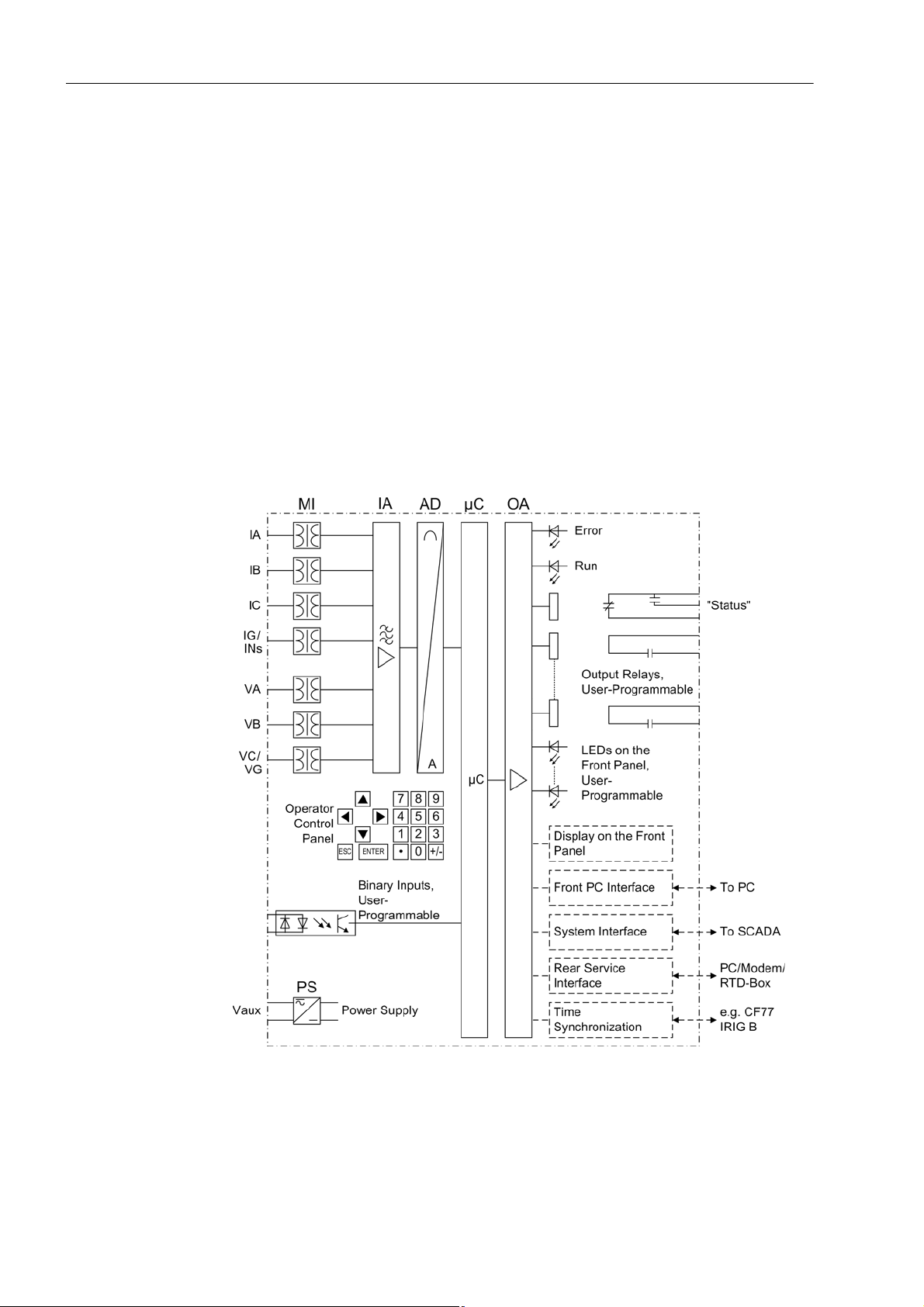
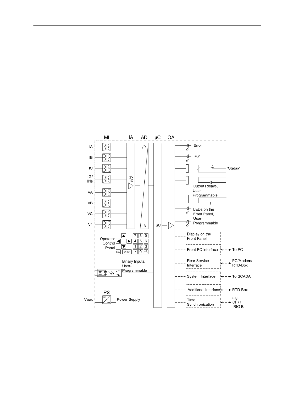
The SIPROTEC 7SJ62/63/64 are numerical, multi-functional, protective and control
devices equipped with a powerful microprocessor. All tasks are processed digitally exclusively , from acquisition of measured values up to commands to the circuit breakers.
Figure 1-1 illustrates the basic structure of the devices 7SJ62/63, Figure 1-2 illustrates
the basic structure of the device 7SJ64.
Analog Inputs The measuring inputs (MI) convert the currents and voltages coming from the instru-
ment transformers and adapt them to the level appropriate for the intern al processing
of the device. The device provides four current inputs. Depending on the model, the
device is also equipped with three or four voltage inputs. Three current inputs serve
for input of the phase currents. Depending on the model, the fourth current input (I
may be used for measuring the ground fault current I
(current transformer starpoint)
N
or for a separate ground current transformer (for sensitive ground fault detection I
and directional determination of ground faults).
N
Ns
)
21
Figure 1-1 Hardware structure of the numerical multi-functional protection device 7SJ62
and 7SJ63
SIPROTEC 4, 7SJ62/63/64 Handbuch
C53000-G1140-C147-A, Edition 07.2015
1.1 Overall Operation
Volt age inp ut s ca n either be use d to measur e the three ph ase-to-g round volt ages, or
two phase-to-phase voltages and the displacement voltage ( V
voltage). It is also pos-
N
sible to connect two phase-to-phase voltages in open-delta connection.
The four voltage transformers of 7SJ64 can either be ap plied for the input of 3 phase-
to-ground voltages, one displacemen t volt age (V
voltage) or a further voltage for the
N
synchronizing function.
The analog input quantities are passed on to the input amplifiers (IA). The input am-
plifier IA stage provides high-resistance term inations for the analog input quantities. It
consists of filters that are optimized for measured-value processing with regard to
bandwidth and processing speed.
The analog-to-digital (AD) stage consists of a multiplexor, an analog-to-digital (A/D)
converter and of memory components for the transmission of digital signals to the microcomputer system.
Figure 1-2 Hardware structure of the numerical multi-functional device 7SJ64
Microcomputer System
Apart from processing the measured values, the microcomp uter system ( μC) also executes the actual protection and control functions. They especially include:
• Filtering and preparation of the measured quantities
• Continuous monitoring of the measured quantities
SIPROTEC 4, 7SJ62/63/64 Handbuch
C53000-G1140-C147-A, Edition 07.2015
22

1 Introduction
• Monitoring of the pickup conditions for the individual protective functions
• Interrogation of limit values and sequences in time
• Control of signals for the logic functions
• Output of control commands for switching devices
• Recording of messages, fault data and fault values for analysis
• Management of the operating system and the associated functions such as data recording, real-time clock, communication, interfaces, etc.
• The information is provided via output amplifiers (OA).
Binary Inputs and Outputs
The computer system obtains external information th ro ug h the bin a ry inp u t/output
modules (inputs and output s). The computer system obtains the information from the
system (e.g remote resetting) or the external equipment (e.g. blocking commands).
Outputs are, in particular, commands to the switchgear units and indications for
remote signalling of important events and statuses.
Front Elements With devices with integrated or detached operator panel, information such as messag-
es related to events, states, measured values and the functional status of the device
are provided via light-emitting diodes (LEDs) and a display screen (LCD) on the front
panel.
Integrated control and numeric keys in conjunction with the LCD facilitate interaction
with the remote device. Via these elements all information of the device such as configuration and setting parameters, operating and fault messages, and measured
values can be accessed. Setting parameters may be changed in the same way.
In addition, control of circuit breakers and other equipment is possible from the front
panel of the device.
Serial Interfaces A serial PC interface on the front panel is pr ovided for local communications with the
device through a personal computer using the operating program DIGSI.This facilitates a comfortable handling of all device functions.
A separate service interface can be provided for remote communication with the
device via a personal computer using DIGSI. This interface is especially well suited for
dedicated connection of the devices to the PC or for operation via a modem. The
service interface can also be used to connect an RTD box (= resistance temperature
detector) for entering external temperatures (e.g. for overload protection).
23
The additional interface (only 7SJ64) is designed exclusively for connection of a
RTD-Box (= resistance temperature detector) for entering external temperatures.
All data can be transferred to a central control center or monitoring system via the
serial system interface. This interface may be provided with various protocols and
physical transmission schemes to suit the particular application.
A further interface is provided for the time synchronization of the internal clock via
external synchronization sources.
Further communication protocols can be realized via additional interface modules.
Over the operating or service interface you can serve the device (only with 7SJ64)
from a distance or locally with a standard Browser . This can take place during the initial
start-up, examination and also during the operation with the devices. For this the
SIPROTEC 4 standard "Web monitor" is available.
SIPROTEC 4, 7SJ62/63/64 Handbuch
C53000-G1140-C147-A, Edition 07.2015

1.1 Overall Operation
Power Supply The before-mentioned function elements and their voltage levels are supplied with
power by a power supplying unit (Vaux or PS). Voltage dips may occur if the voltage
supply system (substation battery) becomes short-circu ited. Usually , th ey are bridged
by a capacitor (see also Technical Data).
SIPROTEC 4, 7SJ62/63/64 Handbuch
C53000-G1140-C147-A, Edition 07.2015
24

1 Introduction
1.2 Application Scope
The numerical, multi-functional SIPROTEC 4 7SJ62/63/64 are versatile devices designed for protection, control and monitoring of busbar feeders. The devices can be
used for line protection in networks that are grounded, low-resistance grounded, ungrounded, or of a compensated neutral point structure. They are suited for networks
that are radial or looped, and for lines with single or multi-terminal feeds. The devices
are equipped with motor protection applicable for asynchronous machines of all sizes.
The devices include the functions that are necessary for protection, monitoring of
circuit breaker positions, and control of the circuit breakers in straight bus applications
or breaker-and-a-half configurations; therefore, the devices can be universally employed. The devices provide excellent backup facilities of differential protective
schemes of lines, transformers, generators, motors, and busbars of all voltage levels.
Protective Functions
Non-directional overcurrent protection (50, 50N, 51, 51N) is the basis of the device.
There are two definite time overcurrent protective elements and one inverse time overcurrent protective element for phase and ground current. For inverse time overcurrent
protective elements, several characteristics of differen t standards are provided. Alternatively, user-defined characteristics can be programmed.
Depending on the version of the device that is or dered, the non-directional overcurrent
protection can be supplemented with directional overcurrent protection (67, 67N),
breaker failure protection (50BF), and sensitive ground fault detection for high-resistance ground faults. The highly sensitive ground fault detection can be directional or
non-directional.
In addition to the fault protection functions already ment ion ed , ot he r pr ot ect i ve fun ctions are available. Some of them depend on the version of the device that is ordered .
These additional functions include frequency protection (81O/U), overvoltage protection (59) and undervoltage protection (27), negative sequence protection (46) and
overload protection (49) with start inhibit for moto rs (66/68) and motor starting p rotection (48), as well as automatic reclosing (79) which allows dif ferent reclosing cycles on
overhead lines. The automatic reclosing system may also be connected externally. To
ensure quick detection of the fault, the device is equipped with a fault locator.
A protection feature can be ordered for the detection of intermittent ground faults
which detects and accumulates transient ground faults.
External detectors account for ambient temperatures or coolant temperatures (by
means of an external RTD-box).
Before reclosing after thre e-pole tripping 7SJ64 can ve rify the validity of the reclosure
by voltage check and/or synchronous check. The synchronization function can also be
controlled externally.
Control Functions The device provides a control function which can be accomplished fo r activa ting an d
deactivating switchgears via the integrated operator panel, the system inter face,
binary inputs, and the serial port using a personal computer with DIGSI.
The status of the primary equipment can be transmitted to the device via auxiliary contacts connected to binary input s. The presen t status (or po sition) of the primar y equipment can be displayed on the device, and used for interlocking or plausibility monitoring. The number of the operating equipment to be switched is limited by the binary
inputs and outputs available in the de vice or the binary inputs and outputs allocated
for the switch position indications. Depending on the primary equipment being con-
25
SIPROTEC 4, 7SJ62/63/64 Handbuch
C53000-G1140-C147-A, Edition 07.2015

1.2 Application Scope
trolled, one binary input (single point indication) or two binary inputs (double point indication) may be used for this process.
The capability of switching primary equipment can be restricted by a setting associated with switching authority (Remote or Local), and by the operating mode (interlocked/non-interlocked, with or without password request).
Processing of interlocking conditions for switching (e.g. switchgear interlocking) can
be established with the aid of integrated, user-configurable logic functions.
Messages and Measured Values; Recording of Event
and Fault Data
The operating messages provide information about conditions in the power system
and the device. Measurement quantities and values that are calculated can be displayed locally and communicated via the serial interfaces.
Device messages can be assigned to a number of LEDs on the front cover (allocatable), can be externally processed via output contacts (allocatable), linked with userdefinable logic functions and/or issued via serial interfaces.
During a fault (system fault) important events and changes in condition s are saved in
fault protocols (Event Log or Trip Log). Instantaneous fault values are also saved in
the device and may be analized subsequently.
Communication Serial interfaces are available for the communication with operating, control and
memory systems.
A 9-pole DSUB socket at the front panel is used for local communication with a per-
sonal computer. By mea ns of the SIPROTEC operating sof tware DIGSI, all operation
and evaluation tasks can be executed via this user interface, such as specifying and
modifying configuration parameters and settings, configuring user-specific logic functions, retrieving operational messages and measured values, inquiring device conditions and measured values, issuing control commands.
Depending on the individual ordering variant, a dditio nal inter faces a re lo ca ted on the
rear side of the device. They serve to est ablish an extensive communication with other
digital operating, control and memory components:
The service interface ca n be operated via electrical d ata lines or fiber optics and also
allows communication via modem. For this reason, remote operation is possible via
personal computer and the DIGSI operating sof tware, e.g. to operate seve ral devices
via a central PC.
The additional port (only 7SJ64) is designed exclusively for connection of a RTD-Box
(= resistance temperature detector) for enteri ng external tempe ratures. It can also be
operated via data lines or fibre optic cables.
The system interface ensures the central communication between the device and the
substation controller. It can also be operated via data lines or fibre optic cables. For
the data transfer S tandard Protocols a ccording IEC 60870 870-5-103 are available via
the system port. The integration of the devices into the automation systems SINAUT
LSA and SICAM can also take place with this profile.
The EN-100-module allows the devices to be integrated in 100-Mbit-Ethernet communication networks in control and automation systems using protocols according to
IEC61850. Besides control system integra tio n, this interf ac e en a ble s DIG S I-c om m unication and inter-relay communication via GOOSE.
Alternatively , a field bus coupling with PROFIBUS FMS is availa ble for SIPROTEC 4.
The PROFIBUS FMS according to DIN 19245 is an open communication standard
that has particularly wide acceptance in process co ntrol and a utomation engineer ing,
with especially high performance. A profile has been de fined for the PROFIBUS com-
SIPROTEC 4, 7SJ62/63/64 Handbuch
C53000-G1140-C147-A, Edition 07.2015
26

1 Introduction
munication that covers all of the information types required for protective and process
control engineering. The integration of the devices into the power automation system
SICAM can also take place with this profile.
Besides the field-bus connection with PROFIBUS FMS, further couplings are possible
with PROFIBUS DP and the protocols DNP3.0 and MODBUS. These protocols do not
support all possibilities which are offered by PROFIBUS FMS.
27
SIPROTEC 4, 7SJ62/63/64 Handbuch
C53000-G1140-C147-A, Edition 07.2015

1.3 Characteristics
1.3 Characteristics
General Characteristics
• Powerful 32-bit microprocessor system.
• Complete digital processing and control of measured values, from the sampling o f
the analog input quantities to the initiation of outputs, for example, tripping or
closing circuit breakers or other switchgear devices.
• T otal ele ctrical separation between the internal processing stages of the device and
the external transformer, control, and DC supply circuits of the system because of
the design of the binary inputs, outputs, and the DC or AC converters.
• Complete set of functions necessary for the proper protection of lines, feeders,
motors, and busbars.
• Easy device operation through an integrated operator panel or by means of a connected personal computer running DIGSI.
• Continuous calculation and display of measured and metered values on the front of
the device.
• Storage of min/max measured values (slave pointer function) and storage of longterm mean values.
• Recording of event and fault data for the last eight system faults (fault in a network)
with real-time information as well as instantaneous values for fault recording for a
maximum time range of 5 s.
• Constant monitoring of the measurement quantities, as well as continuous self-diagnostics covering the hardware and software.
Time Overcurrent Protection 50, 51, 50N, 51N
• Communication with SCADA or substation controller equipment via ser ial interfaces
through the choice of data cable, modem, or optical fibers.
• Battery-buffered clock that can be synchronized with an IRIG-B (via satellite) or
DCF77 signal, binary input signal, or system interface command.
• Statistics: Recording of the number of trip signals instigated by the device and
logging of currents switched off last by the device, as well as accumulated short
circuit currents of each pole of the circuit breaker.
• Operating Hours Counter: Tracking of operating hours of the equipment being protected.
• Commissioning aids such as connection check, direction determination, status indication of all binary inputs and outputs, easy check of system interface and influencing of information of the system interface during test operation
• Two defin ite time overcurrent protective elemen ts and one inverse time overcurrent
protective element for phase current and ground current I
3I
;
0
• Two-phase operation of the overcurrent protection (I
or summation current
N
, IC) possible;
A
• Different curves of common standards are available for 51 and 51N, or a userdefined characteristic;
• Blocking capability e.g. for reverse interlocking with any element;
• Instantaneous tripping by any overcurrent element upon switch onto fault is possible;
• Second harmonic inrush restraint.
SIPROTEC 4, 7SJ62/63/64 Handbuch
C53000-G1140-C147-A, Edition 07.2015
28
 Loading...