

Siemens SIPROTEC PROFINET IO User Manual

Preface
Contents
SIPROTEC
Communication Module
PROFINET IO
Communication Profile
Using PROFINET IO 1
PROFINET IO in SIPROTEC 2
Parameterization 3
PROFINET IO Diagnosis 4
Technical Data 5
Glossary
Index
C53000-L1840-C360-1

NOTE
For your own safety, observe the warnings and safety instructions contained in this document.
Disclaimer of Liability
This document has been subjected to rigorous technical review
before being published. It is revised at regular intervals, and any
modifications and amendments are included in the subsequent
issues. The content of this document has been compiled for
information purposes only. Although Siemens AG has made best
efforts to keep the document as precise and up-to-date as possible,
Siemens AG shall not assume any liability for defects and damage
which result through use of the information contained herein.
This content does not form part of a contract or of business
relations; nor does it change these. All obligations of Siemens AG
are stated in the relevant contractual agreements.
Siemens AG reserves the right to revise this document from time to
time.
Document version: C53000-L1840-C360-1.00
Edition: 08.2012
Product version: V1.00
Copyright
Copyright © Siemens AG 2012. All rights reserved.
The disclosure, duplication, distribution and editing of this
document, or utilization and communication of the content are not
permitted, unless authorized in writing. All rights, including rights
created by patent grant or registration of a utility model or a design,
are reserved.
Registered Trademarks
SIMATIC
SIMEAS
trademarks of Siemens AG. An unauthorized use is illegal.
All other designations in this document can be trademarks whose
use by third parties for their own purposes can infringe the rights of
the owner.
®
, SIMATIC NET®, SIPROTEC®, DIGSI®, SICAM®,
®
, SINAUT® , OSCOP®, and DAKON® are registered

Preface
Purpose of this Manual
This manual describes the communication profile of the SIPROTEC 4 Communication Modules with
PROFINET IO. The protocol is available on the electrical and the optical EN100 module.
Target Audience
Protection engineers, commissioning engineers, persons who are involved in setting, testing and service of
protection, automation, and control devices, as well as operation personnel in electrical plants and power
plants.
Scope of Validity of this Manual
This manual is valid for the SIPROTEC 4 Communication Modules with PROFINET IO.
Additional Support
Should further information be desired or should particular problems arise which are not covered sufficiently for
the purpose of the purchaser, the matter should be referred to the local Siemens representative.
Our Customer Support Center provides around-the-clock support.
Phone: +49 (180) 524-8437
Fax: +49 (180) 524-2471
Internet: http://www.siprotec.com
E-mail: support.ic@siemens.com
Training Courses
If you are interested in our current training program, contact our training center:
Siemens AG
Siemens Power Academy TD
Humboldtstr. 59
D-90459 Nuremberg
Germany
Phone: +49 (911) 433-7415
Fax: +49 (911) 433-7929
e-mail: power-academy.energy@siemens.com
Internet: www.siemens.com/energy/power-academy
C53000-L1840-C360-1, Edition 08.2012
3SIPROTEC 4, Communication Module PROFINET IO, Communication Profile
Safety Notes
This manual does not constitute a complete catalog of all safety measures required for operating the equipment
(module, device) in question, because special operating conditions may require additional measures. However,
it does contain notes that must be adhered to for your own personal safety and to avoid material damage.
These notes are highlighted with a warning triangle and different keywords indicating different degrees of
danger.
DANGER
Danger means that death or severe injury will occur if the appropriate safety measures are not taken.
✧ Follow all advice instructions to prevent death or severe injury.
WARNING
Warning means that death or severe injury can occur if the appropriate safety measures are not taken.
✧ Follow all advice instructions to prevent death or severe injury.
CAUTION
Caution means that minor or moderate injury can occur if the appropriate safety measures are not taken.
✧ Follow all advice instructions to prevent minor injury.
NOTICE
Notice means that material damage can occur if the appropriate safety measures are not taken.
✧ Follow all advice instructions to prevent material damage.
NOTE
is important information about the product, the handling of the product, or the part of the documentation in
question to which special attention must be paid.
4 SIPROTEC 4, Communication Module PROFINET IO, Communication Profile
C53000-L1840-C360-1, Edition 08.2012

Qualified Personnel
Commissioning and operation of the equipment (module, device) described in this manual must be performed
by qualified personnel only. As used in the safety notes contained in this manual, qualified personnel are those
persons who are authorized to commission, release, ground and tag devices, systems, and electrical circuits
in accordance with safety standards.
Intended Use
The equipment (device, module) must not be used for any other purposes than those described in the
Catalog and the Technical Description. If it is used together with third-party devices and components, these
must be recommended or approved by Siemens.
If the device is not used as specified in the production information and the manual, the intended protection
function is impaired.
The correct and safe operation of the product requires adequate transportation, storage, installation, and
mounting as well as appropriate use and maintenance.
When operating electric equipment, certain parts of the equipment inevitably carry hazardous voltages. Severe
injury or material damage can occur if the appropriate measures are not taken:
• Before making any connections, ground the equipment at the grounding terminal.
• Hazardous voltages can be present on all switching components connected to the power supply.
• Even after the supply voltage has been disconnected can hazardous voltages still be present in the
equipment (capacitor storage).
• Equipment with current transformer circuits must not be operated while being open.
• The limiting values specified in the manual or the product information must not be exceeded; this also
refers to testing and commissioning
C53000-L1840-C360-1, Edition 08.2012
5SIPROTEC 4, Communication Module PROFINET IO, Communication Profile

6 SIPROTEC 4, Communication Module PROFINET IO, Communication Profile
C53000-L1840-C360-1, Edition 08.2012

Contents
Preface . . . . . . . . . . . . . . . . . . . . . . . . . . . . . . . . . . . . . . . . . . . . . . . . . . . . . . . . . . . . . . . . . . . . . . . . . . . . . . . . . . 3
1 Using PROFINET IO. . . . . . . . . . . . . . . . . . . . . . . . . . . . . . . . . . . . . . . . . . . . . . . . . . . . . . . . . . . . . . . . . . . . . . . . 9
1.1 General . . . . . . . . . . . . . . . . . . . . . . . . . . . . . . . . . . . . . . . . . . . . . . . . . . . . . . . . . . . . . . . . . . . . . . . . . 10
1.2 Documents . . . . . . . . . . . . . . . . . . . . . . . . . . . . . . . . . . . . . . . . . . . . . . . . . . . . . . . . . . . . . . . . . . . . . . 12
1.3 Application Example . . . . . . . . . . . . . . . . . . . . . . . . . . . . . . . . . . . . . . . . . . . . . . . . . . . . . . . . . . . . . . . 13
1.4 Additional Ethernet Services and Protocols . . . . . . . . . . . . . . . . . . . . . . . . . . . . . . . . . . . . . . . . . . . . . 14
1.5 Firmware Update . . . . . . . . . . . . . . . . . . . . . . . . . . . . . . . . . . . . . . . . . . . . . . . . . . . . . . . . . . . . . . . . . 15
2 PROFINET IO in SIPROTEC . . . . . . . . . . . . . . . . . . . . . . . . . . . . . . . . . . . . . . . . . . . . . . . . . . . . . . . . . . . . . . . . 17
2.1 Identification of Module and Firmware . . . . . . . . . . . . . . . . . . . . . . . . . . . . . . . . . . . . . . . . . . . . . . . . . 18
2.2 Device Identification . . . . . . . . . . . . . . . . . . . . . . . . . . . . . . . . . . . . . . . . . . . . . . . . . . . . . . . . . . . . . . . 20
2.3 Data-Type Definitions for IO Data Exchange . . . . . . . . . . . . . . . . . . . . . . . . . . . . . . . . . . . . . . . . . . . . 21
2.3.1 Data Type Single-Point Indication (SP, Input). . . . . . . . . . . . . . . . . . . . . . . . . . . . . . . . . . . . . . . . . 21
2.3.2 Data Type Single Command (SC, Output) . . . . . . . . . . . . . . . . . . . . . . . . . . . . . . . . . . . . . . . . . . . 22
2.3.3 Data Type Double-Point Indication (DP, Input)/Double Command (DC, Output) . . . . . . . . . . . . . . 23
2.3.4 Measured Values and Statistic Values . . . . . . . . . . . . . . . . . . . . . . . . . . . . . . . . . . . . . . . . . . . . . . 24
2.3.5 Metered Values. . . . . . . . . . . . . . . . . . . . . . . . . . . . . . . . . . . . . . . . . . . . . . . . . . . . . . . . . . . . . . . . 25
2.3.6 Message Block for Event List and Process Alarm . . . . . . . . . . . . . . . . . . . . . . . . . . . . . . . . . . . . . 26
2.3.7 Unit IDs, Units, and Unit Multipliers. . . . . . . . . . . . . . . . . . . . . . . . . . . . . . . . . . . . . . . . . . . . . . . . . 28
2.4 IO Modules . . . . . . . . . . . . . . . . . . . . . . . . . . . . . . . . . . . . . . . . . . . . . . . . . . . . . . . . . . . . . . . . . . . . . . 29
2.5 Assignment of IO Modules to SIPROTEC Data Objects . . . . . . . . . . . . . . . . . . . . . . . . . . . . . . . . . . . 38
2.6 Event List . . . . . . . . . . . . . . . . . . . . . . . . . . . . . . . . . . . . . . . . . . . . . . . . . . . . . . . . . . . . . . . . . . . . . . . 41
2.6.1 Input Direction. . . . . . . . . . . . . . . . . . . . . . . . . . . . . . . . . . . . . . . . . . . . . . . . . . . . . . . . . . . . . . . . . 41
2.6.2 Output Direction . . . . . . . . . . . . . . . . . . . . . . . . . . . . . . . . . . . . . . . . . . . . . . . . . . . . . . . . . . . . . . . 43
2.6.3 Handshake Mechanism (Example) . . . . . . . . . . . . . . . . . . . . . . . . . . . . . . . . . . . . . . . . . . . . . . . . . 44
2.7 Process Alarm . . . . . . . . . . . . . . . . . . . . . . . . . . . . . . . . . . . . . . . . . . . . . . . . . . . . . . . . . . . . . . . . . . . 45
2.8 Acyclic Reading and Writing of Data . . . . . . . . . . . . . . . . . . . . . . . . . . . . . . . . . . . . . . . . . . . . . . . . . . 46
2.8.1 Presetting and Resetting Metered Values and Statistic Values . . . . . . . . . . . . . . . . . . . . . . . . . . . 46
2.8.2 Reading Unit IDs of Measured Values, Statistic Values, and Metered Values . . . . . . . . . . . . . . . . 47
2.8.3 Reading Conversion Factors of Metered Values . . . . . . . . . . . . . . . . . . . . . . . . . . . . . . . . . . . . . . 48
2.9 Executing Switching Operations via PROFINET IO . . . . . . . . . . . . . . . . . . . . . . . . . . . . . . . . . . . . . . . 49
2.9.1 Command Output Types for Switchgear Control . . . . . . . . . . . . . . . . . . . . . . . . . . . . . . . . . . . . . . 49
2.9.2 Recommended Transmission of Commands via PROFINET IO . . . . . . . . . . . . . . . . . . . . . . . . . . 50
2.9.3 Multiple Command Output . . . . . . . . . . . . . . . . . . . . . . . . . . . . . . . . . . . . . . . . . . . . . . . . . . . . . . . 51
2.9.4 Behavior During Special Operating Conditions. . . . . . . . . . . . . . . . . . . . . . . . . . . . . . . . . . . . . . . . 51
2.10 Behavior When Communication to IO Controller is Faulted . . . . . . . . . . . . . . . . . . . . . . . . . . . . . . . . . 52
C53000-L1840-C360-1, Edition 08.2012
7SIPROTEC 4, Communication Module PROFINET IO, Communication Profile

2.11 Indications to the IO Controller. . . . . . . . . . . . . . . . . . . . . . . . . . . . . . . . . . . . . . . . . . . . . . . . . . . . . . . 52
2.12 Time Synchronization. . . . . . . . . . . . . . . . . . . . . . . . . . . . . . . . . . . . . . . . . . . . . . . . . . . . . . . . . . . . . . 53
2.13 PROFINET IO and IEC 61850/GOOSE . . . . . . . . . . . . . . . . . . . . . . . . . . . . . . . . . . . . . . . . . . . . . . . . 53
2.14 Media Redundancy . . . . . . . . . . . . . . . . . . . . . . . . . . . . . . . . . . . . . . . . . . . . . . . . . . . . . . . . . . . . . . . 54
3 Parameterization . . . . . . . . . . . . . . . . . . . . . . . . . . . . . . . . . . . . . . . . . . . . . . . . . . . . . . . . . . . . . . . . . . . . . . . . . 55
3.1 Configuration of EN100 Network Parameters . . . . . . . . . . . . . . . . . . . . . . . . . . . . . . . . . . . . . . . . . . . 56
3.2 Parameterization with DIGSI . . . . . . . . . . . . . . . . . . . . . . . . . . . . . . . . . . . . . . . . . . . . . . . . . . . . . . . . 57
3.2.1 Inserting and Configuring a New Project . . . . . . . . . . . . . . . . . . . . . . . . . . . . . . . . . . . . . . . . . . . . 57
3.2.2 Setting the Interfaces . . . . . . . . . . . . . . . . . . . . . . . . . . . . . . . . . . . . . . . . . . . . . . . . . . . . . . . . . . . 63
3.2.3 Customizing the Routings . . . . . . . . . . . . . . . . . . . . . . . . . . . . . . . . . . . . . . . . . . . . . . . . . . . . . . . 65
3.3 Parameterizing the IO Controller . . . . . . . . . . . . . . . . . . . . . . . . . . . . . . . . . . . . . . . . . . . . . . . . . . . . . 75
3.3.1 PROFINET IO Configuration . . . . . . . . . . . . . . . . . . . . . . . . . . . . . . . . . . . . . . . . . . . . . . . . . . . . . 75
3.3.2 Siemens S7 PLC and Step7. . . . . . . . . . . . . . . . . . . . . . . . . . . . . . . . . . . . . . . . . . . . . . . . . . . . . . 75
3.4 DCP - Discovery and Basic Configuration Protocol . . . . . . . . . . . . . . . . . . . . . . . . . . . . . . . . . . . . . . . 81
3.4.1 Network Settings and Device Name. . . . . . . . . . . . . . . . . . . . . . . . . . . . . . . . . . . . . . . . . . . . . . . . 81
3.4.2 Reset to Default Settings . . . . . . . . . . . . . . . . . . . . . . . . . . . . . . . . . . . . . . . . . . . . . . . . . . . . . . . . 82
3.4.3 Device Identification . . . . . . . . . . . . . . . . . . . . . . . . . . . . . . . . . . . . . . . . . . . . . . . . . . . . . . . . . . . . 82
4 PROFINET IO Diagnosis. . . . . . . . . . . . . . . . . . . . . . . . . . . . . . . . . . . . . . . . . . . . . . . . . . . . . . . . . . . . . . . . . . . 85
4.1 Diagnosis HTML Page of EN100 . . . . . . . . . . . . . . . . . . . . . . . . . . . . . . . . . . . . . . . . . . . . . . . . . . . . . 86
4.2 PROFINET IO Error Indication in the SIPROTEC 4 Device. . . . . . . . . . . . . . . . . . . . . . . . . . . . . . . . . 91
4.3 I&M - Identification and Maintenance. . . . . . . . . . . . . . . . . . . . . . . . . . . . . . . . . . . . . . . . . . . . . . . . . . 93
5 Technical Data . . . . . . . . . . . . . . . . . . . . . . . . . . . . . . . . . . . . . . . . . . . . . . . . . . . . . . . . . . . . . . . . . . . . . . . . . . . 95
5.1 Technical Data of the EN100 . . . . . . . . . . . . . . . . . . . . . . . . . . . . . . . . . . . . . . . . . . . . . . . . . . . . . . . . 96
Glossary. . . . . . . . . . . . . . . . . . . . . . . . . . . . . . . . . . . . . . . . . . . . . . . . . . . . . . . . . . . . . . . . . . . . . . . . . . . . . . . . 97
Index. . . . . . . . . . . . . . . . . . . . . . . . . . . . . . . . . . . . . . . . . . . . . . . . . . . . . . . . . . . . . . . . . . . . . . . . . . . . . . . . . . 101
8 SIPROTEC 4, Communication Module PROFINET IO, Communication Profile
C53000-L1840-C360-1, Edition 08.2012

1 Using PROFINET IO
1.1 General 10
1.2 Documents 12
1.3 Application Example 13
1.4 Additional Ethernet Services and Protocols 14
1.5 Firmware Update 15
C53000-L1840-C360-1, Edition 08.2012
9SIPROTEC 4, Communication Module PROFINET IO, Communication Profile

1 Using PROFINET IO
1.1 General
1.1 General
Application
The Ethernet-based fieldbus protocol PROFINET IO is used in SIPROTEC 4 devices equipped with the
100 Mbit EN100 Ethernet module. The PROFINET IO communication protocol is defined in the standards
IEC 61158 and IEC 61748.
NOTE
In this manual, the following short forms are used: EN100 for the 100 Mbit EN100 Ethernet module, SIPROTEC
for SIPROTEC 4, and DIGSI for the DIGSI 4 parameterization software.
PROFINET IO is used as additional communication protocol in the EN100 besides the IEC 61850/GOOSE
protocol and can be used in parallel with this protocol (see Chapter 2.13).
PROFINET IO is used mainly in industrial energy automation.
Requirements
The SIPROTEC device you are using must support the PROFINET IO protocol. Refer to the associated device
manual in this context.
Enter the required settings using the DIGSI parameterization software, version 4.85 or higher.
To set the PROFINET IO protocol, DIGSI must contain the IEC 61850 station configurator.
The parameterization is described in Chapter 3.2.1.
Scope of Delivery
The following device variants with EN100 modules are available when using the PROFINET IO protocol:
• SIPROTEC device with integrated EN100 and implemented PROFINET IO protocol:
− SIPROTEC device with EN100-E+ (electrical bus interface): RJ45 connection for Ethernet
− SIPROTEC device with EN100-O+ (optical bus interface): LC connection, multimode fiber cable
• EN100 with implemented PROFINET IO protocol for retrofittings at existing devices or for replaced EN100
modules:
− EN100-E+ (electrical bus interface): RJ45 connection for Ethernet;
order no. C53207-A351-D688-1
− EN100-O+ (optical bus interface): LC connection, multimode fiber cable;
order no. C53207-A351-D689-1
The following manuals provide detailed information on the EN100 module and the IEC 61850 protocol:
• German edition: Handbuch Ethernetmodul EN100, Bestellnr. C53000-G1100-C167-x
• English edition: Manual Ethernet Module EN100, order no. C53000-G1140-C167-x
Extended Scope of Delivery
In addition to the scope of delivery mentioned previously, you can download the following components from the
Internet:
• PROFINET IO firmware as PCK file
• PROFINET IO GSDML file
• MIB files for SNMP
• Various manuals: communication profile, bus mapping files
10 SIPROTEC 4, Communication Module PROFINET IO, Communication Profile
C53000-L1840-C360-1, Edition 08.2012

1 Using PROFINET IO
To download the files, go to the following Internet address:
http://siemens.siprotec.de/download_neu/index_e.htm
In addition, you can purchase various Ethernet patch cables as shown in the following table.
Table 1-1 Ethernet Patch Cable (Double Shielded (SFPT), LAN Connector Plugs on Both Sides)
Cable Length Order No.
0.5 m 7KE6000-8G-D00-0AA5
1.0 m 7KE6000-8G-D00-1AA0
2.0 m 7KE6000-8G-D00-2AA0
3.0 m 7KE6000-8G-D00-3AA0
5.0 m 7KE6000-8G-D00-5AA0
10.0 m 7KE6000-8G-D01-0AA0
15.0 m 7KE6000-8G-D01-5AA0
1.1 General
20.0 m 7KE6000-8G-D02-0AA0
NOTE
Multimode optical fibers in various lengths fitted with LC duplex connectors on both sides are available for the
optical EN100 module. See also the ordering information at:
http://siemens.siprotec.de/download_neu/accessories/6XV81xx/6XV8100_FO_Order_Information_102010_en.pdf
C53000-L1840-C360-1, Edition 08.2012
11SIPROTEC 4, Communication Module PROFINET IO, Communication Profile

1 Using PROFINET IO
1.2 Documents
1.2 Documents
Documents for PROFINET IO
You can obtain documents and up-to-date information on PROFINET from the PROFIBUS/PROFINET
international user organization at the Internet address:
http://www.profibus.com
Documents for Bus Mapping
The bus mapping documents describe the data objects which are available in a SIPROTEC device for
PROFINET IO.
You can download the bus mapping documents for each device type from the Internet at the following address:
http://siemens.siprotec.de/download_neu/index_e.htm
Example: SIPROTEC 7SJ61/62/64 Multifunctional Protection Relay - PROFINET IO Bus Mapping,
order number: C53000-L1800-C361-x
Documents for EN100
The following manuals contain information on the functions available on the EN100 in addition to
PROFINET IO, such as IEC 61850, HTML pages, SNMP, etc.:
• German edition: Handbuch Ethernetmodul EN100, Bestellnr. C53000-G1100-C167-x
• US English edition: Manual Ethernet Module EN100, order no. C53000-G1140-C167-x
12 SIPROTEC 4, Communication Module PROFINET IO, Communication Profile
C53000-L1840-C360-1, Edition 08.2012
1.3 Application Example
SIPROTEC 4 device 1
EN100 module
(IO device)
RJ45
SIPROTEC 4 device 2
RJ45
Ethernet
switch
RJ45RJ45
RJ45
Substation controller
IO con tro ll er
RJ45
PROFINET IO
GOOSE
RJ45
...
SIPROTEC 4 device n
RJ45
GOOSE
EN100 module
(IO device)
EN100 module
(IO device)
Engineering station
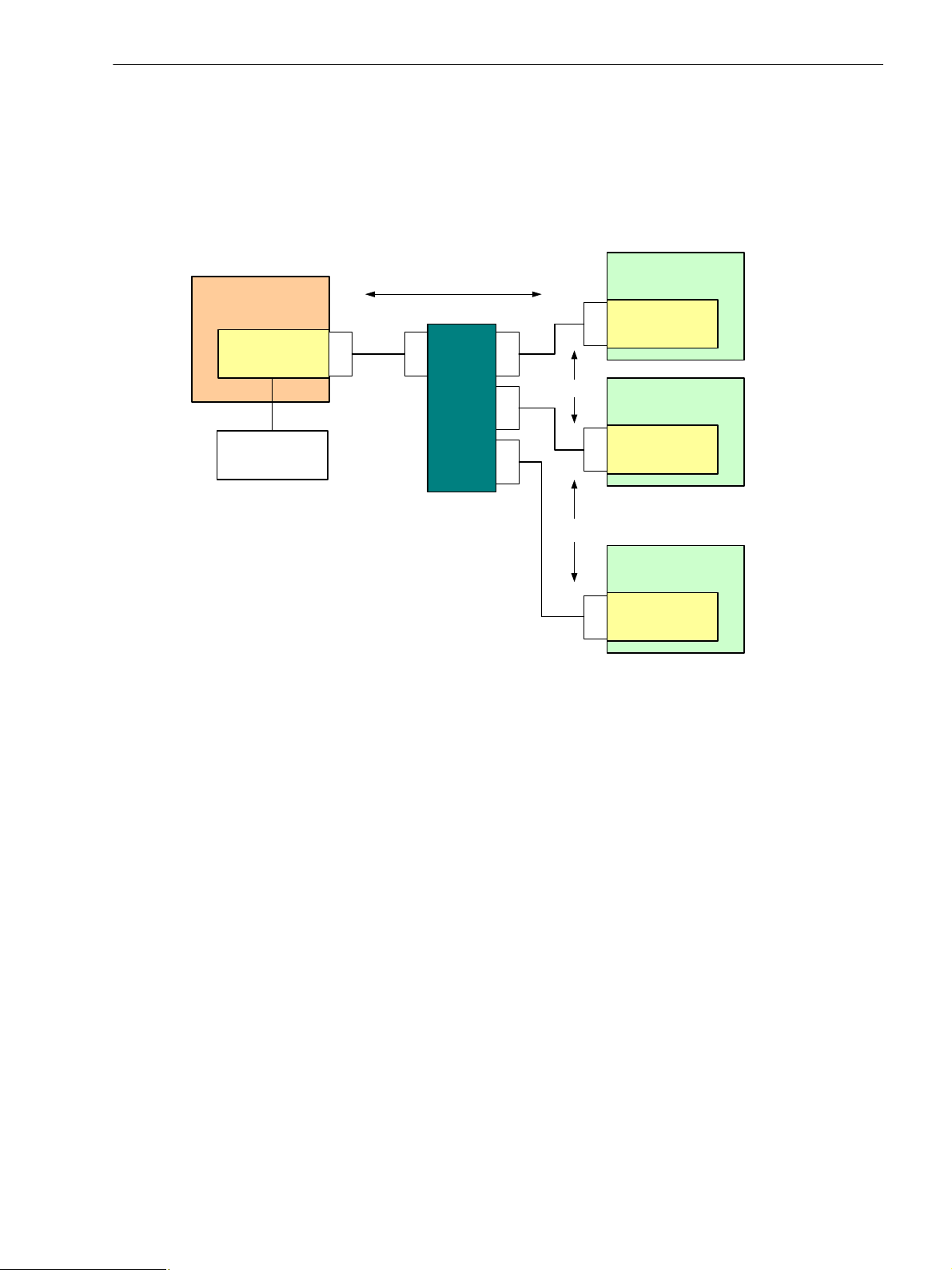
Figure 1-1 shows an application example for SIPROTEC devices with PROFINET IO protocol and GOOSE.
Here, data is exchanged between the substation/IO controller and SIPROTEC/IO device via PROFINET IO
protocol. Each IO device is identified by a name and an IP address. The SIPROTEC devices can exchange
data with each other via GOOSE. The bus nodes can be connected to the Ethernet as the communication
medium via one or multiple Ethernet switches.
1 Using PROFINET IO
1.3 Application Example
Figure 1-1 Application Example Communication
C53000-L1840-C360-1, Edition 08.2012
13SIPROTEC 4, Communication Module PROFINET IO, Communication Profile

1 Using PROFINET IO
1.4 Additional Ethernet Services and Protocols
1.4 Additional Ethernet Services and Protocols
The following additional services and protocols are supported on the EN100. These services can be switched
ON or OFF using DIGSI. Siemens recommends switching off unused services for security reasons.
Services
• Module homepage (HTTP)
• Firmware upgrade (HTTP)
• DIGSI 4 over EN100
• SNMP V2
• IEC 61850 and GOOSE
•SNTP
For more information, refer to the following manual:
Ethernet Module EN100 for IEC 61850 with Electrical/Optical 100 Mbit Interface,
Order number C53000-G1140-C167-x
14 SIPROTEC 4, Communication Module PROFINET IO, Communication Profile
C53000-L1840-C360-1, Edition 08.2012

1.5 Firmware Update
The SIPROTEC devices or the single EN100 modules for retrofitting of SIPROTEC devices already contain the
PROFINET IO firmware on delivery.
Check before installation of the SIPROTEC device or EN100 module that the latest version of the
PROFINET IO module firmware is loaded (ref. to Chapter 2.1).
The Ethernet interface is used for updating the firmware of the PROFINET IO module.
Observe the notes and procedures described in the following documents:
• Firmware/FPGA Update via the Ethernet interface of the EN100 module:
http://siemens.siprotec.de/download_neu/devices/1_General/Protocols/IEC_61850/
EN100%20FW%204.20/EN100_FW_Update_V2.12_en.pdf
• Manual Ethernet Module EN100, Order no. C53000-G1140-C167-x:
http://siemens.siprotec.de/download_neu/devices/1_General/Doku_Protokolle/Englisch/IEC_61850/
COM_IEC61850_MODUL_A10_US.pdf
The PROFINET IO firmware file has the name PROFINET-IO_VXX.YY.ZZ.pck (XX.YY.ZZ = version number).
If a PROFINET IO firmware update is available then the self-extracting file PROFINET-IO_XX.YY.ZZ.exe can
be downloaded from the Internet address:
1 Using PROFINET IO
1.5 Firmware Update
http://siemens.siprotec.de/download_neu/index_e.htm
NOTE
A valid network configuration (IP address, subnet mask) is required on the EN100 module for the firmware
update. Setting the network configuration can be done with a device configuration in DIGSI or using DCP, e.g.
with the Primary Setup Tool (ref. to Chapter 3.4).
C53000-L1840-C360-1, Edition 08.2012
15SIPROTEC 4, Communication Module PROFINET IO, Communication Profile

1 Using PROFINET IO
1.5 Firmware Update
16 SIPROTEC 4, Communication Module PROFINET IO, Communication Profile
C53000-L1840-C360-1, Edition 08.2012

2 PROFINET IO in SIPROTEC
2.1 Identification of Module and Firmware 18
2.2 Device Identification 20
2.3 Data-Type Definitions for IO Data Exchange 21
2.4 IO Modules 29
2.5 Assignment of IO Modules to SIPROTEC Data Objects 38
2.6 Event List 41
2.7 Process Alarm 45
2.8 Acyclic Reading and Writing of Data 46
2.9 Executing Switching Operations via PROFINET IO 49
2.10 Behavior When Communication to IO Controller is Faulted 52
2.11 Indications to the IO Controller 52
2.12 Time Synchronization 53
2.13 PROFINET IO and IEC 61850/GOOSE 53
2.14 Media Redundancy 54
C53000-L1840-C360-1, Edition 08.2012
17SIPROTEC 4, Communication Module PROFINET IO, Communication Profile
2 PROFINET IO in SIPROTEC
2.1 Identification of Module and Firmware
2.1 Identification of Module and Firmware
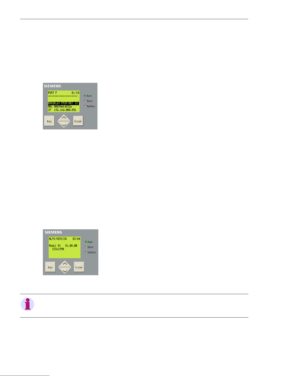
Module Information Menu
Available on HMI display or via Web monitor:
✧ Select Enter → Test/Diagnosis → Module info → Port F (in 7SC80) or Port B (depending on the
device).
The following information is shown, for example: module type, communication protocol, network settings
Figure 2-1 Module Information
Module type:
• EN100-E+ - EN100 with electrical Ethernet interface
• EN100-O+ - EN100 with optical fiber Ethernet interface
Communication protocol:
• IEC 61850 - IEC 61850/GOOSE
• PROFINET IO - PROFINET IO with IEC 61850/GOOSE option
MLFB/Version Menu
Available on HMI display or via Web monitor:
✧ Select Enter → Settings → Setup/Extras → MLFB/Version, then scroll down twice
to show the version number of the firmware on EN100
Figure 2-2 MLFB/Version (Note: Module F in 7SC80)
NOTE
The firmware identification IEC 61850 is always displayed here, also when PROFINET IO firmware is loaded.
HTML Page of the EN100 Module (refer to Chapter 4.1)
• If PROFINET IO firmware is loaded, the DNP IP menu is available in the navigation window.
• The firmware version is shown on the homepage of EN100.
18 SIPROTEC 4, Communication Module PROFINET IO, Communication Profile
C53000-L1840-C360-1, Edition 08.2012
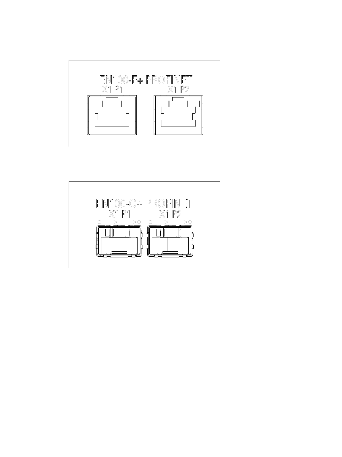
Labeling of the PROFINET module
The EN100 modules with PROFINET IO on the rear panel of the SIPROTEC device are labeled as follows:
Figure 2-3 Labeling EN100-E+ with PROFINET IO
2 PROFINET IO in SIPROTEC
2.1 Identification of Module and Firmware
Figure 2-4 Labeling EN100-O+ with PROFINET IO
Meaning of the labeling:
• X1: PROFINET IO interface
• X1 P1: PROFINET IO port 1 (identification as "port-001" via LLDP and SNMP)
• X1 P2: PROFINET IO port 2 (identification as "port-002" via LLDP and SNMP)
C53000-L1840-C360-1, Edition 08.2012
19SIPROTEC 4, Communication Module PROFINET IO, Communication Profile

2 PROFINET IO in SIPROTEC
2.2 Device Identification
2.2 Device Identification
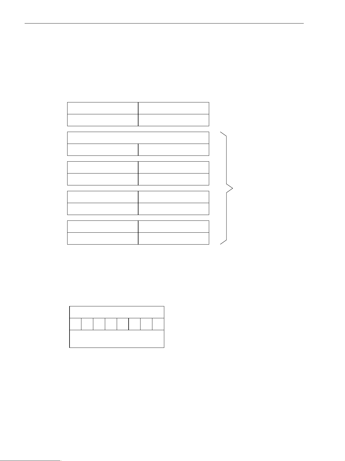
Each PROFINET IO device requires a unique device identification. This device identification consists of the
Vendor_ID and the Device_ID, with the Device_ID comprising the device class and device family.
The device identification for a PROFINET IO device in SIPROTEC 4 devices is:
0x002A0E03
and is composed as follows:
Table 2-1 Device Identification
Vendor_ID Device_ID
Device class Device family
0x002a
(Siemens AG)
The device identification is stored, for example, in the GSDML file, see Chapter 3.3.1.
0E
(Protection and PQ)
03
(SIPROTEC 4)
20 SIPROTEC 4, Communication Module PROFINET IO, Communication Profile
C53000-L1840-C360-1, Edition 08.2012

2.3 Data-Type Definitions for IO Data Exchange
2
0
27 to 2
4
2
3
2
2
2
1
...
Bit x+2 Bit xBit x+1Bit x+3
SP 1SP 2
8 single-point indications max. per byte
SP 4 SP 3
... ...
2.3 Data-Type Definitions for IO Data Exchange
The following data types and definitions are used to exchange data between the IO device and IO controller
via PROFINET IO:
• Single-point indication
• Single command
• Double-point indication and double command
• Measured value and statistic value
• Metered value
• Message block for event list and process alarm
• Units and unit multiples
2.3.1 Data Type Single-Point Indication (SP, Input)
Number of byte values: 1/8 (1 bit)
Range of values:
0 = OFF
2 PROFINET IO in SIPROTEC
1 = ON
Figure 2-5 Data Type: Single-Point Indication
Status of Indications
The status (valid or invalid) is relevant for indications which are, for example, received in the SIPROTEC device
with a GOOSE telegram and subsequently read by the IO controller via PROFINET IO.
A single-point indication containing the status of an indication can be created with CFC (Continuous Function
Chart) in DIGSI using the SI_GET_STATUS function block. This second indication can be used in addition to
the value for the transmission via PROFINET IO.
C53000-L1840-C360-1, Edition 08.2012
21SIPROTEC 4, Communication Module PROFINET IO, Communication Profile

2 PROFINET IO in SIPROTEC
2
0
27 to 2
4
2
3
2
2
2
1
...
Bit 0 Bit 0Bit 1Bit 1
SC 1SC 2
4 single commands max. per byte
... ...
2.3 Data-Type Definitions for IO Data Exchange
2.3.2 Data Type Single Command (SC, Output)
Number of byte values: 1/4 (2 bits)
Range of values:
0 = idle state bit 1 = 0 and bit 0 = 0
1 = OFF bit 1 = 0 and bit 0 = 1
2 = ON bit 1 = 1 and bit 0 = 0
3 = not allowed bit 1 = 1 and bit 0 = 1
NOTE
Single commands of the SIPROTEC device are controlled via PROFINET IO using 2 bits (analogous to double
commands, see Chapter 2.3.3).
The switching direction OFF for single commands with pulse output is not permitted and is rejected in the
SIPROTEC device.
Figure 2-6 Data Type: Single Command
22 SIPROTEC 4, Communication Module PROFINET IO, Communication Profile
C53000-L1840-C360-1, Edition 08.2012

2 PROFINET IO in SIPROTEC
2
0
27 to 2
4
2
3
2
2
2
1
...
Bit 0 Bit 0Bit 1Bit 1
DP/DC 1
4 double-point indications/double commands max. per byte
DP/DC 2
...
...
2.3 Data-Type Definitions for IO Data Exchange
2.3.3 Data Type Double-Point Indication (DP, Input)/Double Command (DC, Output)
Number of byte values: 1/4 (2 bits)
Range of values:
0 = "not applicable"/
disturbed state for DP and
idle state for DC bit 1 = 0 and bit 0 = 0
1 = OFF bit 1 = 0 and bit 0 = 1
2 = ON bit 1 = 1 and bit 0 = 0
3 = disturbed state for DP,
not allowed for DC bit 1 = 1 and bit 0 = 1
NOTE
Depending on the data type selected in DIGSI, the values 0 and 3 for double-point indications have the
following meaning:
− Type DP: 0 = "not applicable", 3 = disturbed state "00" or disturbed state "11"
− Type DP_I: 0 = "not applicable" or disturbed state "00", 3 = disturbed state "11"
"not applicable": the indication is not routed (not connected to a binary input)
Figure 2-7 Data Type: Double-Point Indication/Double Command
NOTE
The data type double command requires the associated command feedback to be parameterized as doublepoint indication.
A double command with a single-point indication as feedback or without feedback acquisition is controlled in
the same way as a single command via PROFINET IO. This means that the processing of a double command
via PROFINET IO depends on the type of the associated feedback.
C53000-L1840-C360-1, Edition 08.2012
23SIPROTEC 4, Communication Module PROFINET IO, Communication Profile

2 PROFINET IO in SIPROTEC
S
1 bit 8 bits 23 bits
Byte 0 (LSB)
Exponent Mantissa
Byte 3 (MSB) Byte 2 Byte 1
... ...
2.3 Data-Type Definitions for IO Data Exchange
2.3.4 Measured Values and Statistic Values
Number of byte values: 4 (32 bits)
Range of values: ±1.7 * 10
Measured values and statistic values are transmitted in 32 bit floating-point format. The format consists of a
sign bit (S), exponent and mantissa as shown in the following:
Figure 2-8 Data Type: Measured Value/Statistic Value
In DIGSI, these values have the following data type:
• Measured values: data type measured value MV
• Statistic values: data type value indication VI
38
Sign Bit (S)
The sign bit (S) is set if measured values are negative.
Measured Values (Mantissa and Exponent)
The value of a measured value is obtained as follows:
0 < Exponent < 255: resulting value = (-1)
Exponent = 0: resulting value = 0
Exponent = 255, mantissa not equal to 0: invalid (Not a Number, NaN)
Quality Information
"Not a Number" (NaN) floating-point numbers are used to specify the quality of measured values.
Table 2-2 Quality Information
Floating-point number
(hexadecimal)
0x7F800000
0x7F800001
Overflow
Invalid
<sign>
(<exponent> - 127)
* 2
* 1,<mantissa>
Status Remark
Overflow of the measured value
Measured value invalid or not computable,
for example frequency or cos φ when
voltage or current is too low.
0x7F800002
Not calculated
0xFF800000 Falling below Falling below the measured value
24 SIPROTEC 4, Communication Module PROFINET IO, Communication Profile
The internal data image was not updated
after a restart.
C53000-L1840-C360-1, Edition 08.2012

2.3.5 Metered Values
S
1 bit 31 bits
Byte 0 (LSB)
Metered value
Byte 3 (MSB) Byte 2 Byte 1
... ...
Number of byte values: 4 (32 bits)
Range of values: 0 to +4 294 967 295
Figure 2-9 Data Type: Metered Value
Status Bit (S)
The metered value with set status bit (S) is invalid for the following reasons:
• Invalid metered value after initial start/restart of the device
(status bit is deleted after 2 restoring intervals of the metered value following initial start/restart)
• The external error bit for pulse metered values for the binary input is set.
2 PROFINET IO in SIPROTEC
2.3 Data-Type Definitions for IO Data Exchange
NOTE
• The metered value in the SIPROTEC device overflows when 7FFFFFFFH + 1 to 0.
• Transmission of the status bit can be disabled in application cases where transmission of the metered
value status bit is not desired or where it could lead to erroneous interpretations during analysis in the IO
controller. In these cases, the status bit always assumes the value 0.
See also Figure 2-16 in this context.
To convert the 32-bit pulse metered value into an energy value in floating-point format, conversion factors can
be determined via acyclic read accesses.
See Chapter 2.4, IO module counters 04 in this context.
C53000-L1840-C360-1, Edition 08.2012
25SIPROTEC 4, Communication Module PROFINET IO, Communication Profile
2 PROFINET IO in SIPROTEC
Identifi cation
Byte 2Byte 1
Value
Byte 4Byte 3
Milliseconds (0 to 59 999)
Hours (0 to 23)
Byte 6Byte 5
Minutes (0 to 59)
Month (1 to 12)
Byte 8Byte 7
Day (1 to 31)
Clock-time status
Byte 10Byte 9
Year (0 = 1900)
Time stamp
in UTC
...
...
1
PROFINET IO mapping
data-object number
Byte 1 - Identification
4567203 Bit position
Meaning
Byte
2.3 Data-Type Definitions for IO Data Exchange
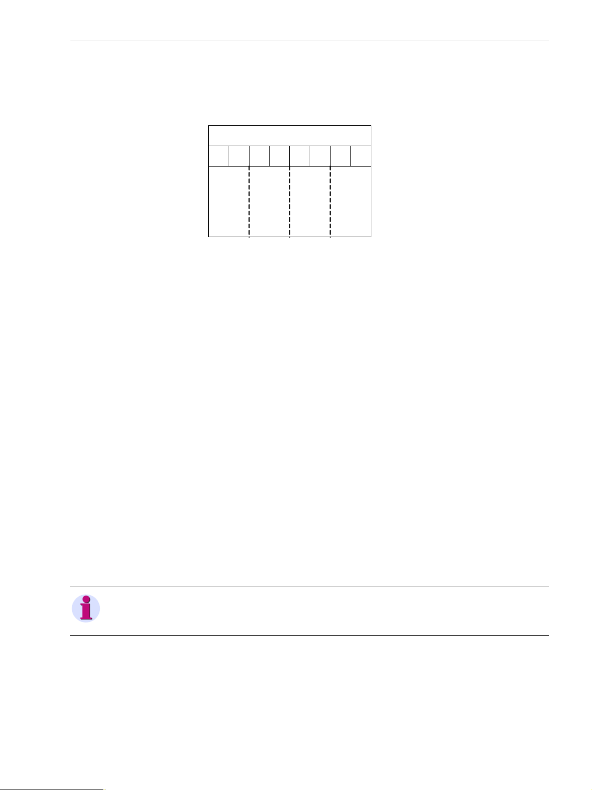
2.3.6 Message Block for Event List and Process Alarm
Number of byte values: 10
The complex data type message block defines an entry in the event list via PROFINET IO (see Chapter 2.6)
and is used for the data field of the summary process alarm (see Chapter 2.7).
The message block contains an identification of the single-point indications and double-point indications which
are sent in the event list or in the process alarm, plus the value and the associated time-stamp information.
Figure 2-10 Data Type: Message Block
Byte 1: Identification
Byte 1 identifies a single-point indication or double-point indication using its PROFINET IO mapping dataobject number.
Figure 2-11 Byte 1 - Identification in the data type Message Block
26 SIPROTEC 4, Communication Module PROFINET IO, Communication Profile
C53000-L1840-C360-1, Edition 08.2012
Byte 2: Value
1
Byte 2 - Value
4567203 Bit position
Meaning
Byte
Reserved = 0
Indication type
Reserved = 0
Value
2 PROFINET IO in SIPROTEC
2.3 Data-Type Definitions for IO Data Exchange
Byte 2 in the message block contains the value of an indication after registering a change, plus an identifier
whether it is a single-point indication or a double-point indication.
Figure 2-12 Byte 2 - Value in the data type Message Block
• Value (bit 0 and bit 1)
− Single-point indication (binary output):
00 = OFF
01 = ON
− Double-point indication (binary output):
00 = disturbed state
01 = OFF
10 = ON
11 = disturbed state
• Indication type (bit 4 and bit 5)
01 = 1 = single-point indication
10 = 2 = double-point indication
Example:
A change from ON to OFF of a single-point indication is transmitted with the value byte:
00010000
bin
= 10
Byte 3 through Byte 10: Time Stamp
The real-time stamp is transmitted with the data depicted in Figure 2-10 for the instant of time the indication
was changed. Time and date are indicated in UTC (Universal Time Coordinated).
NOTE
Correction factors for daylight saving time and local settings are not considered.
Meaning of the clock status (byte 9):
•00
C53000-L1840-C360-1, Edition 08.2012
•20
= time is valid
hex
= time is invalid (clock failure)
hex
hex
.
27SIPROTEC 4, Communication Module PROFINET IO, Communication Profile

2 PROFINET IO in SIPROTEC
2.3 Data-Type Definitions for IO Data Exchange
2.3.7 Unit IDs, Units, and Unit Multipliers
The following unit IDs are assigned to the units of the measured values, statistic values and metered values:
Table 2-3 Units and Unit Multipliers
ID Unit,
unit multiplier
ID Unit,
unit multiplier
ID Unit,
unit multiplier
1 dimensionless 33 kΩ 172 MWh
3 % 51 W 173 GWh
4 ° 53 kW 174 kvar
5 °C 54 MW 175 Mvar
11 A 61 VA 176 Gvar
12 mA 63 kVA 177 kvarh
13 kA 64 MVA 178 Mvarh
17 h 71 Hz 179 Gvarh
21 V 92 km 184 GVA
22 mV 95 miles 185 °F
23 kV 170 GW 203 MOhm
31 Ω 171 kWh - -
The unit IDs can be read via acyclic telegrams, see Chapter 2.8.2.
28 SIPROTEC 4, Communication Module PROFINET IO, Communication Profile
C53000-L1840-C360-1, Edition 08.2012
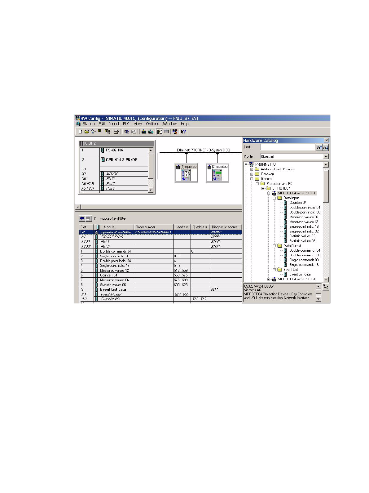
2.4 IO Modules
The IO modules described in the following are available for the PROFINET IO configuration of the SIPROTEC
devices in the IO controller. For this purpose, the GSDML file, which contains the description of the IO modules,
is loaded into the parameterization software of the IO controller.
Figure 2-13 shows an example for selecting the IO modules of the SIPROTEC IO device with electrical
Ethernet interface in the Siemens parameterization software Step7 and a configuration example of a
SIPROTEC device for PROFINET IO. For more information on the parameterization, refer to Chapter 3.
2 PROFINET IO in SIPROTEC
2.4 IO Modules
Figure 2-13 Parameterization Example
C53000-L1840-C360-1, Edition 08.2012
29SIPROTEC 4, Communication Module PROFINET IO, Communication Profile
2 PROFINET IO in SIPROTEC
2.4 IO Modules
PROFINET IO Bus Interface DAP (Device Access Point)
The DAP module is always plugged in at slot 0 of the IO device and cannot be removed. The module describes
the physical device data such as interface and port. In addition, it is possible to read or write device-related
diagnoses and acyclic telegrams.
Cyclic data exchange None
Acyclic reading/writing of data
(standard PROFINET IO services)
Acyclic reading/writing of data
(SIPROTEC-specific)
Parameters None
*) I&M data = data for device identification and maintenance
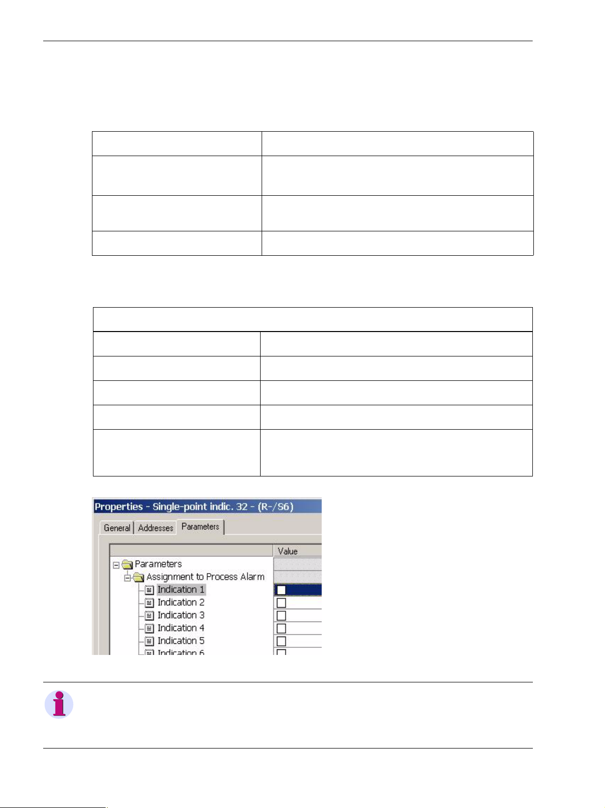
IO Module Single-Point Indications 16
Category in the hardware catalog Input data
Data type 16 single-point indications; see Chapter 2.3.1
Data size 2 bytes
Acyclic reading/writing of data None
Parameters Each single-point indication can be assigned to the process alarm
• Reading of diagnostics data and I&M data 0, 1, 2, 3, 4
• Writing of I&M data 1, 2, 3, 4
None
Single-point indications 16
(see Chapter 2.7).
Default setting: all not assigned
*)
Figure 2-14 Single-Point Indication 16
NOTE
The indication number indication x (see Figure 2-14) is not identical with the PROFINET IO mapping dataobject number. It refers to the indication in this IO module. The indication number in each IO module starts with
number 1.
30 SIPROTEC 4, Communication Module PROFINET IO, Communication Profile
C53000-L1840-C360-1, Edition 08.2012
 Loading...