

Siemens Siprotec DNP3 IP Communications Manual

C53000-L2040-C354-1
SIPROTEC
Communication Module
DNP3 IP
Communication Profile
Preface
Contents
Characteristic of the DNP3 IP Module 1
Configuration in DIGSI 4 2
Scaling and Thresholds for Transmission 3
Time Synchronization 4
DNP3 IP Diagnosis for EN100-Module 5
Technical Data 6
Index

Disclaimer of Liability
This document has been subjected to rigorous technical review
before being published. It is revised at regular intervals, and any
modifications and amendments are included in the subsequent
issues. The content of this document has been compiled for
information purposes only. Although Siemens AG has made best
efforts to keep the document as precise and up-to-date as possible,
Siemens AG shall not assume any liability for defects and damage
which result through use of the information contained herein.
This content does not form part of a contract or of business
relations; nor does it change these. All obligations of Siemens AG
are stated in the relevant contractual agreements.
Siemens AG reserves the right to revise this document from time to
time.
Document Release: C53000-L2040-C354-1.00
Edition: 02.2012
Product version: V1.00
Copyright
Copyright © Siemens AG 2012. All rights reserved.
The disclosure, duplication, distribution and editing of this
document, or utilization and communication of the content are not
permitted, unless authorized in writing. All rights, including rights
created by patent grant or registration of a utility model or a design,
are reserved.
Registered Trademarks
SIMATIC
®
, SIMATIC NET®, SIPROTEC®, DIGSI®, SICAM®,
SIMEAS
®
, SINAUT® , OSCOP®, and DAKON® are registered
trademarks of SIEMENS AG. An unauthorized use is illegal.
All other designations in this document can be trademarks whose
use by third parties for their own purposes can infringe the rights of
the owner.
NOTE
For your own safety, please observe the warnings and safety instructions contained in this document.

3SIPROTEC, Communication Module, Communication Profile
C53000-L2040-C354-1, Edition 02.2012
Preface
Purpose of this manual
This manual describes the communication profile of the SIPROTEC Communication Module with DNP3 IP.
Target group
Protection engineers, commissioning engineers, persons who are involved in setting, testing and service of
protection, automation, and control devices, as well as operation personnel in electrical plants and power stations.
Scope of validity of this manual
This manual is valid for the SIPROTEC Communication Module with DNP3 IP.
Further support
Should further information be desired or should particular problems arise which are not covered sufficiently for
the purchaser's purpose, the matter should be referred to the local Siemens representative.
Hotline
Our Customer Support Center provides around-the-clock support.
Phone: +49 (180) 524-7000
Fax: +49 (180) 524-2471
Internet: http://www.siprotec.com
e-mail: support.energy@siemens.com
Training courses
If you are interested in our current training program, please contact our training center:
Siemens AG
Siemens Power Academy TD
Humboldtstr. 59
D-90459 Nuremberg
Germany
Phone: +49 (911) 433-7415
Fax: +49 (911) 433-7929
e-mail: td.power-academy.energy@siemens.com
Internet: www.siemens.com/energy/power-academy

Preface
4 SIPROTEC, Communication Module, Communication Profile
C53000-L2040-C354-1, Edition 02.2012
Notes On Safety
This manual does not constitute a complete catalog of all safety measures required for operating the equipment
(module, device) in question, because special operating conditions may require additional measures. However,
it does contain notes that must be adhered to for your own personal safety and to avoid damage to property.
These notes are highlighted with a warning triangle and different keywords indicating different degrees of danger.
DANGER
Danger means that death or severe injury will occur if the appropriate safety measures are not taken.
✧ Follow all advice instructions to prevent death or severe injury.
WARNING
Warning means that death or severe injury can occur if the appropriate safety measures are not taken.
✧ Follow all advice instructions to prevent death or severe injury.
CAUTION
Caution means that minor or moderate injury can occur if the appropriate safety measures are not taken.
✧ Follow all advice instructions to prevent minor injury.
NOTICE
Notice means that damage to property can occur if the appropriate safety measures are not taken.
✧ Follow all advice instructions to prevent damage to property.
NOTE
is important information about the product, the handling of the product, or the part of the documentation in question to which special attention must be paid.

Preface
5SIPROTEC, Communication Module, Communication Profile
C53000-L2040-C354-1, Edition 02.2012
Qualified Personnel
Commissioning and operation of the equipment (module, device) described in this manual must be performed
by qualified personnel only. As used in the safety notes contained in this manual, qualified personnel are those
persons who are authorized to commission, release, ground and tag devices, systems, and electrical circuits
in accordance with safety standards.
Use as Prescribed
The equipment (device, module) must not be used for any other purposes than those described in the
Catalog and the Technical Description. If it is used together with third-party devices and components, these
must be recommended or approved by Siemens.
Correct and safe operation of the product requires adequate transportation, storage, installation, and
mounting as well as appropriate use and maintenance.
During the operation of electrical equipment, it is unavoidable that certain parts of this equipment will carry dangerous voltages. Severe injury or damage to property can occur if the appropriate measures are not taken:
• Before making any connections at all, ground the equipment at the PE terminal.
• Hazardous voltages can be present on all switching components connected to the power supply.
• Even after the supply voltage has been disconnected, hazardous voltages can still be present in the equipment (capacitor storage).
• Equipment with current transformer circuits must not be operated while open.
• The limit values indicated in the manual or the operating instructions must not be exceeded; this also
refers to testing and commissioning

Preface
6 SIPROTEC, Communication Module, Communication Profile
C53000-L2040-C354-1, Edition 02.2012

7SIPROTEC, Communication Module, Communication Profile
C53000-L2040-C354-1, Edition 02.2012
Contents
Preface . . . . . . . . . . . . . . . . . . . . . . . . . . . . . . . . . . . . . . . . . . . . . . . . . . . . . . . . . . . . . . . . . . . . . . . . . . . . . . . . . . 3
1 Characteristic of the DNP3 IP Module . . . . . . . . . . . . . . . . . . . . . . . . . . . . . . . . . . . . . . . . . . . . . . . . . . . . . . . . . 9
1.1 General . . . . . . . . . . . . . . . . . . . . . . . . . . . . . . . . . . . . . . . . . . . . . . . . . . . . . . . . . . . . . . . . . . . . . . . . . 10
1.2 Identification of Module and Firmware . . . . . . . . . . . . . . . . . . . . . . . . . . . . . . . . . . . . . . . . . . . . . . . . . 12
1.3 Supported DNP3 IP Object Types . . . . . . . . . . . . . . . . . . . . . . . . . . . . . . . . . . . . . . . . . . . . . . . . . . . . 13
1.4 Table of Parameters . . . . . . . . . . . . . . . . . . . . . . . . . . . . . . . . . . . . . . . . . . . . . . . . . . . . . . . . . . . . . . . 15
1.5 DNP3 IP Networking Parameters . . . . . . . . . . . . . . . . . . . . . . . . . . . . . . . . . . . . . . . . . . . . . . . . . . . . . 17
1.6 Buffered Events . . . . . . . . . . . . . . . . . . . . . . . . . . . . . . . . . . . . . . . . . . . . . . . . . . . . . . . . . . . . . . . . . . 18
1.7 File Transfer/Reading of Fault Records . . . . . . . . . . . . . . . . . . . . . . . . . . . . . . . . . . . . . . . . . . . . . . . . 19
1.8 Further Ethernet Services and Protocols . . . . . . . . . . . . . . . . . . . . . . . . . . . . . . . . . . . . . . . . . . . . . . . 23
1.8.1 Services . . . . . . . . . . . . . . . . . . . . . . . . . . . . . . . . . . . . . . . . . . . . . . . . . . . . . . . . . . . . . . . . . . . . . 23
1.8.2 DNP3 IP with IEC 61850 and GOOSE . . . . . . . . . . . . . . . . . . . . . . . . . . . . . . . . . . . . . . . . . . . . . . 23
2 Configuration in DIGSI 4 . . . . . . . . . . . . . . . . . . . . . . . . . . . . . . . . . . . . . . . . . . . . . . . . . . . . . . . . . . . . . . . . . . . 25
2.1 Inserting and Adjusting of a New Project . . . . . . . . . . . . . . . . . . . . . . . . . . . . . . . . . . . . . . . . . . . . . . . 26
2.2 Setting the Interfaces . . . . . . . . . . . . . . . . . . . . . . . . . . . . . . . . . . . . . . . . . . . . . . . . . . . . . . . . . . . . . . 31
2.3 Customization of the Allocations. . . . . . . . . . . . . . . . . . . . . . . . . . . . . . . . . . . . . . . . . . . . . . . . . . . . . . 33
3 Scaling and Thresholds for Transmission . . . . . . . . . . . . . . . . . . . . . . . . . . . . . . . . . . . . . . . . . . . . . . . . . . . . 43
3.1 Measured Value Scaling. . . . . . . . . . . . . . . . . . . . . . . . . . . . . . . . . . . . . . . . . . . . . . . . . . . . . . . . . . . . 44
3.2 Measured Value Threshold Processing . . . . . . . . . . . . . . . . . . . . . . . . . . . . . . . . . . . . . . . . . . . . . . . . 46
3.3 Counter Value Scaling . . . . . . . . . . . . . . . . . . . . . . . . . . . . . . . . . . . . . . . . . . . . . . . . . . . . . . . . . . . . . 47
4 Time Synchronization . . . . . . . . . . . . . . . . . . . . . . . . . . . . . . . . . . . . . . . . . . . . . . . . . . . . . . . . . . . . . . . . . . . . . 49
4.1 General . . . . . . . . . . . . . . . . . . . . . . . . . . . . . . . . . . . . . . . . . . . . . . . . . . . . . . . . . . . . . . . . . . . . . . . . . 50
4.2 Time Synchronization with DNP3 IP. . . . . . . . . . . . . . . . . . . . . . . . . . . . . . . . . . . . . . . . . . . . . . . . . . . 50
5 DNP3 IP Diagnosis for EN100-Module. . . . . . . . . . . . . . . . . . . . . . . . . . . . . . . . . . . . . . . . . . . . . . . . . . . . . . . . 53
5.1 HTML Page. . . . . . . . . . . . . . . . . . . . . . . . . . . . . . . . . . . . . . . . . . . . . . . . . . . . . . . . . . . . . . . . . . . . . . 54
5.2 SNMP . . . . . . . . . . . . . . . . . . . . . . . . . . . . . . . . . . . . . . . . . . . . . . . . . . . . . . . . . . . . . . . . . . . . . . . . . . 57
5.3 DNP3 IP Error Indication . . . . . . . . . . . . . . . . . . . . . . . . . . . . . . . . . . . . . . . . . . . . . . . . . . . . . . . . . . . 58
6 Technical Data . . . . . . . . . . . . . . . . . . . . . . . . . . . . . . . . . . . . . . . . . . . . . . . . . . . . . . . . . . . . . . . . . . . . . . . . . . . 61
6.1 Technical Data of EN100 . . . . . . . . . . . . . . . . . . . . . . . . . . . . . . . . . . . . . . . . . . . . . . . . . . . . . . . . . . . 62
Index . . . . . . . . . . . . . . . . . . . . . . . . . . . . . . . . . . . . . . . . . . . . . . . . . . . . . . . . . . . . . . . . . . . . . . . . . . . . . . . . . . . 63

Contents
8 SIPROTEC, Communication Module, Communication Profile
C53000-L2040-C354-1, Edition 02.2012

9SIPROTEC, Communication Module, Communication Profile
C53000-L2040-C354-1, Edition 02.2012
1 Characteristic of the DNP3 IP Module
1.1 General 10
1.2 Identification of Module and Firmware 12
1.3 Supported DNP3 IP Object Types 13
1.4 Table of Parameters 15
1.5 DNP3 IP Networking Parameters 17
1.6 Buffered Events 18
1.7 File Transfer/Reading of Fault Records 19
1.8 Further Ethernet Services and Protocols 23
1 Characteristic of the DNP3 IP Module
1.1 General
10 SIPROTEC, Communication Module, Communication Profile
C53000-L2040-C354-1, Edition 02.2012
1.1 General
With the EN100 module firmware DNP3 IP from version V1.00, the Ethernet-based DNP3 IP protocol is implemented in addition to other transmission protocols (e.g. IEC 61850 and GOOSE, see chapter 1.7) in the
100 Mbit Ethernet module EN100.
The required settings are made using the DIGSI 4 parameterization software from version 4.85.
Detailed information on the EN100 module and the IEC 61850 engineering is given in the manuals:
• German edition: Handbuch Ethernetmodul EN100, Bestellnr. C53000-G1100-C167-x
• US-english edition: Manual Ethernet Module EN100, order no. C53000-G1140-C167-x
Abbreviations are used in the following text:
• for 100-MBit Ethernet module EN100: EN100
• for DNP3 IP over the internet protocol suite: DNP3 IP
Application
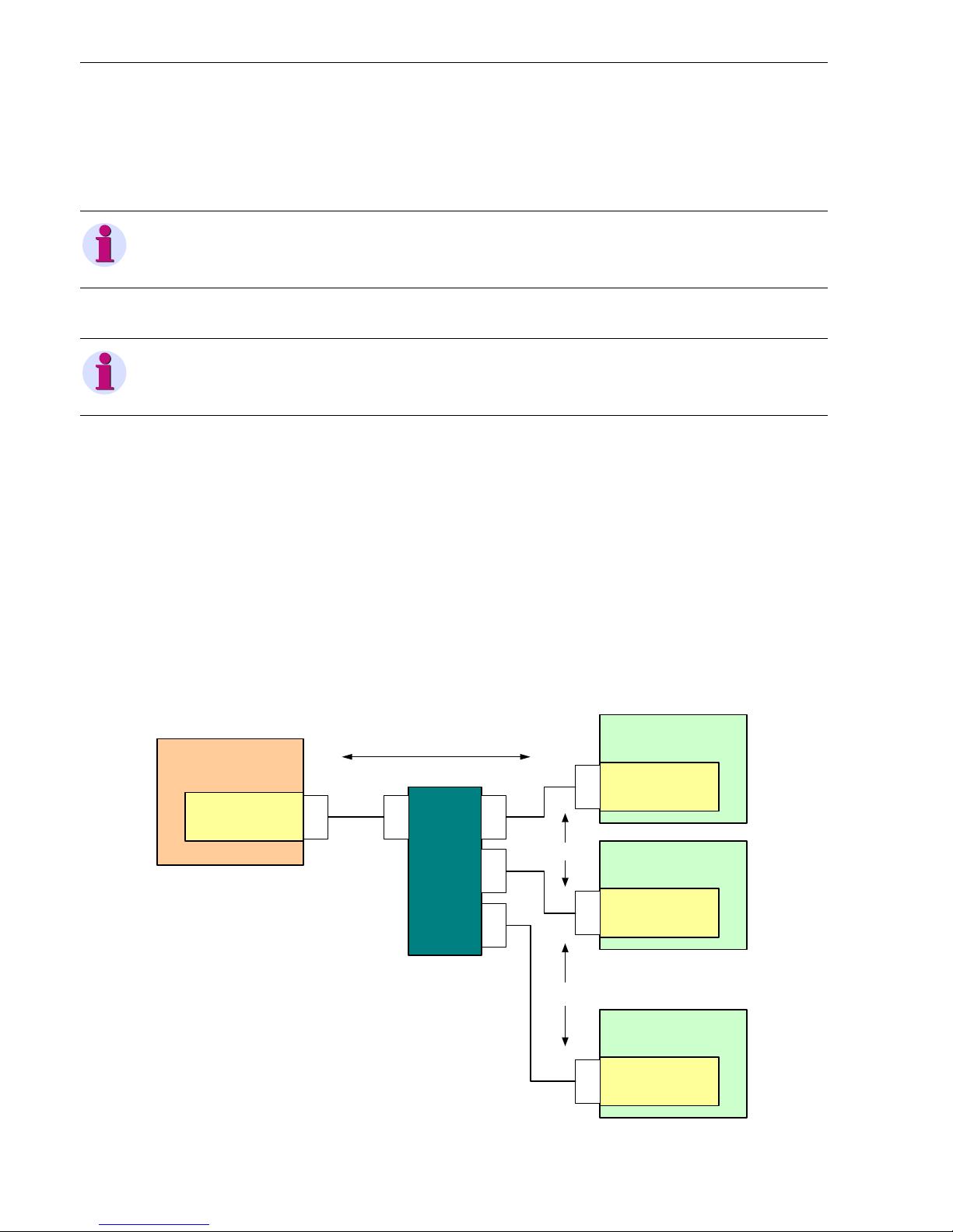
Figure 1-1 shows an application example of the SIPROTEC devices with DNP3 IP and GOOSE in an installation where DNP3 IP is used for communication to a substation controller and GOOSE for inter-device data exchange.
Fig. 1-1 Application Communication
NOTE
Refer to your device manual to find out whether the device you are using supports the DNP3 IP protocol.
NOTE
For the configuration of DNP3 IP a DIGSI 4 packet is required with IEC 61850 station configurator.
SIPROTEC Device 1
EN100 Module
(DN P3 IP Outstati on
and GOOSE)
RJ45
SIPROTEC Device 2
RJ45
Ethernet
Switch
RJ45RJ45
RJ45
Substation
Controller
DNP3 IP Master
RJ45
DNP 3 IP
GOOSE
RJ45
...
SIPROTEC Device n
RJ45
GOOSE
EN100 Module
(DN P3 IP Outstati on
and GOOSE)
EN100 Module
(DN P3 IP Outstati on
and GOOSE)

1 Characteristic of the DNP3 IP Module
1.1 General
11SIPROTEC, Communication Module, Communication Profile
C53000-L2040-C354-1, Edition 02.2012
Documents for DNP3 IP
All relevant information on DNP3 IP is contained in the following documents:
• DNP3Spec-V1-Introduction-20071215.pdf
• DNP3Spec-V2-Part1-ApplicationLayer- 20090315.pdf
• DNP3Spec-V2-Part2-ApplicationLayer- 20090315.pdf
• DNP3Spec-V2-Part3-ApplicationLayer-20071215.pdf
• DNP3Spec-V2-Sup1-SecureAuthentication-20100317.pdf
• DNP3Spec-V3-TransportFunction-20070203.pdf
• DNP3Spec-V4-DataLinkLayer-20070203.pdf
• DNP3Spec-V5-LayerIndependent-20071215.pdf
• DNP3Spec-V6-Part1-ObjectLibraryBasics-20071215.pdf
• DNP3Spec-V6-Part2-Objects-20090315.pdf
• DNP3Spec-V6-Part3-ParsingCodes-20090420.pdf
• DNP3Spec-V7-IPNetworking-20070711.pdf
• DNP3Spec-V8-Apdx1-DeviceProfile-20100223.pdf
• DNP3Spec-V8-Interoperability-20090611.pdf
For more information, go to http://www.dnp.org.
Bus Mapping Documents
You can download the bus mapping document for each device type at the following address:
http://siemens.siprotec.de/download_neu/index_e.htm
The bus mapping documents describe the data objects available via DNP3 IP.
Example: Manual SIPROTEC Feeder Automation Controller 7SC80, order number C53000-L2040-C353
Accessories
Table 1-1Ethernet Patch Cable (double shielded (SFPT), LAN connector plugs on both sides)
Cable Length Order No.
0.5 m 7KE6000-8G-D00-0AA5
1.0 m 7KE6000-8G-D00-1AA0
2.0 m 7KE6000-8G-D00-2AA0
3.0 m 7KE6000-8G-D00-3AA0
5.0 m 7KE6000-8G-D00-5AA0
10.0 m 7KE6000-8G-D01-0AA0
15.0 m 7KE6000-8G-D01-5AA0
20.0 m 7KE6000-8G-D02-0AA0
1 Characteristic of the DNP3 IP Module
1.2 Identification of Module and Firmware
12 SIPROTEC, Communication Module, Communication Profile
C53000-L2040-C354-1, Edition 02.2012
1.2 Identification of Module and Firmware
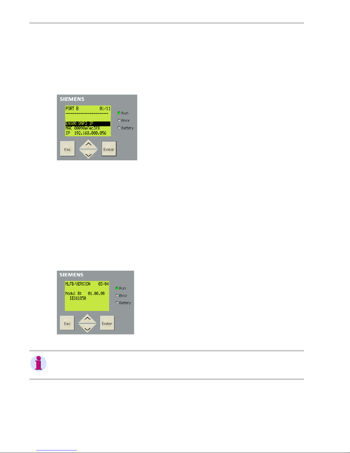
Modulinfo Menu
Available on HMI display or via WebMonitor:
✧ Select Enter → Test/Diagnosis → Modulinfo → Port B (or Port F in 7SC80)
shows e.g. module type, communication protocol, network settings
Fig. 1-2 Modulinfo
Modul type:
• EN100 - EN100 module with electrical Ethernet interface
• EN100_O - EN100 module with fiber-optical Ethernet interface
Communication protocol:
• IEC61850 - IEC 61850/GOOSE
• DNP3 IP - DNP3 IP with IEC61850/GOOSE option (see chapter 1.8.2)
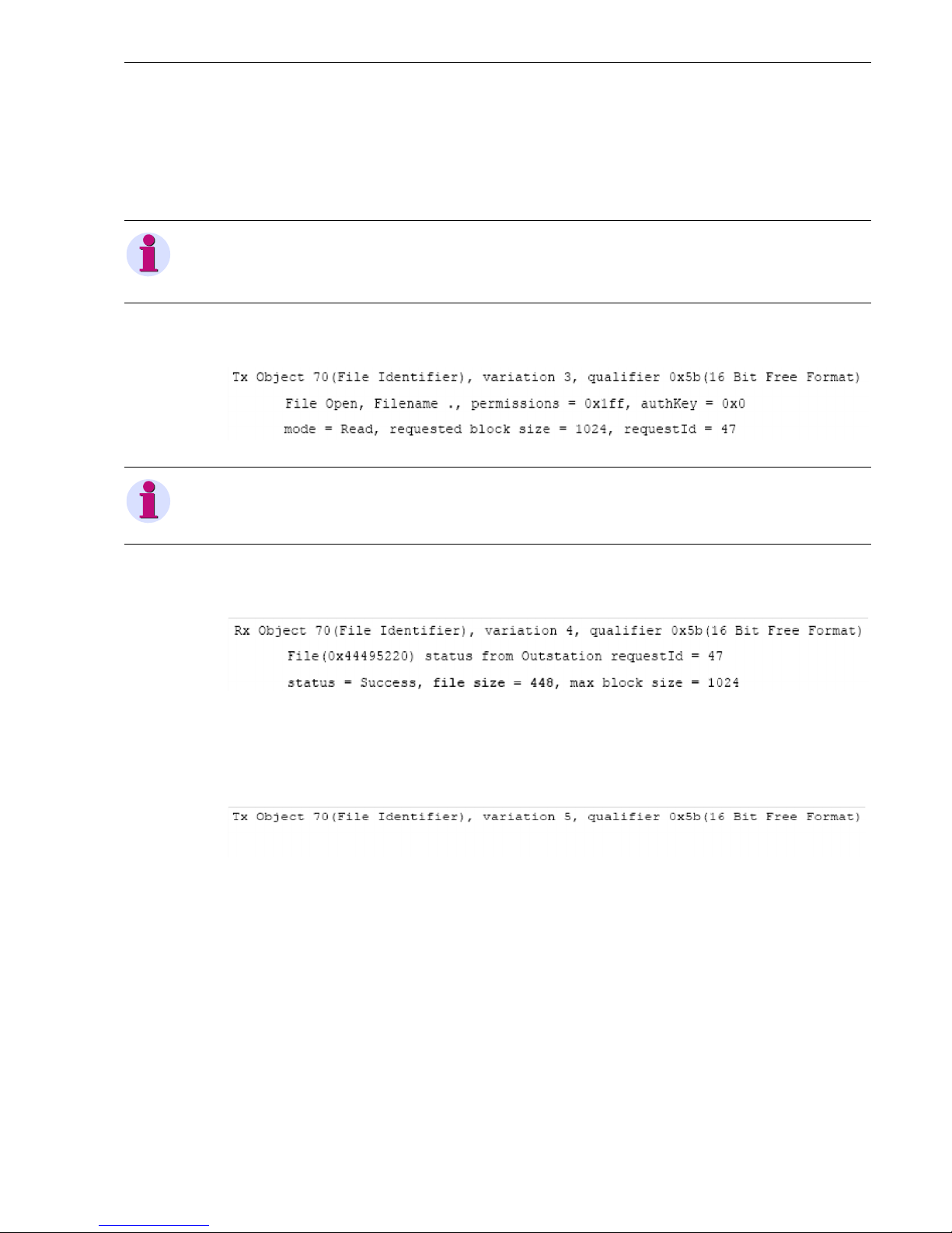
MLFB/Version Menu
Available on HMI display or via WebMonitor:
✧ Select Enter → Settings → Setup/Extras → MLFB/Version, then scroll down twice
shows the version number of the firmware on EN100 module
Fig. 1-3 MLFB/Version (Note: Modul F in 7SC80)
HTML page of the EN100 module
Refer to chapter 5.1.
• If DNP3 IP firmware is loaded then the menu DNP IP is available in the navigation pane.
• The firmware version is shown on the button of the homepage.
NOTE
Always the firmware identifcation IEC61850 is shown here, also when DNP3 IP firmware is loaded.

1 Characteristic of the DNP3 IP Module
1.3 Supported DNP3 IP Object Types
13SIPROTEC, Communication Module, Communication Profile
C53000-L2040-C354-1, Edition 02.2012
1.3 Supported DNP3 IP Object Types
The DNP3 IP interface of the SIPROTEC device supports the following object types:
Table 1-2 Supported DNP3 IP Object Types
Object
Number
Var iati on
Number
Object Description
01 2 Binary Input with Status Object 01, variation 2 describe the state of a
digital input channel or internal software information.
They are also used during a general interrogation.
02 2 Binary Input Change with
Time
Object 02, variation 2 describe the changes of a
digital input channel or of internal software information with the associated change time. The
binary input changes are used for spontaneous
process events.
10 2 Binary Output with Status Object 10, variation 2 describe the status of a
binary output channel.
They are also used during a general interrogation.
The control relay output block (see object 12)
controls the binary output channels.
12 1 Control Relay Output Block Object 12, variation 1 are used for commands for
the process or for setting up internal functions.
20 1 32-bit Binary Counter
(with flag)
Object 20, variation 1 describe the state of
metered values and pulse counters.
They are also used during a general interrogation.
22 1 32-bit Counter Change
Event without Time
Object 22, variation 1 describe the change of
metered values and pulse counters.
30 1 32-bit Analog Input
(used for 32-bit statistic
values)
Object 30, variation 1 describe the state of statistic values, DIGSI 4 data type VI (Value Indica-
tion).
They are also used during a general interrogation.
30 2 16-bit Analog Input
(used for measured values)
Object 30, variation 2 describe the state of measured values, DIGSI 4 data type MV, and min/
max values, DIGSI 4 data type MVT (Measured
Value with Time).
They are also used during a general interrogation.
32 1 32-bit Analog Change
Event without Time
Object 32, variation 1 describe the change of statistic values, DIGSI 4 data type VI (Value Indica-
tion).

1 Characteristic of the DNP3 IP Module
1.3 Supported DNP3 IP Object Types
14 SIPROTEC, Communication Module, Communication Profile
C53000-L2040-C354-1, Edition 02.2012
32 2 16-bit Analog Change
Event without Time
Object 32, variation 2 describe the change of
measured values, DIGSI 4 data type MV, and
min/max values, DIGSI 4 data type MVT (Mea-
sured Value with Time).
50 1 Time and Date Write function:
The time and date object are used for time synchronization.
Read function:
Read the system time of the device.
Date and time are displayed in milliseconds from
January 1, 1970-01-01 00:00:00.000 UTC.
60 1 Class 0 Data With these objects different classes of informa-
tion elements can be read:
• The class 0 contains all static data.
• The classes 1 to 3 contain groups of events
from information elements.
• The data from class 1 has the highest priority, followed by class 2 and class 3.
60 2 Class 1 Data
60 3 Class 2 Data
60 4 Class 3 Data
70 3 File Command Transfer of fault record files.
70 4 File Command Status
70 5 File Transfer
70 6 File Transfer Status
70 7 File Descriptor
80 1 Internal Indications Write the value 0 to index 7 leads to reset of the
bit DEVICE_RESTART in the flag byte for all
data objects. Writing to index 4 resets the
NEED_TIME bit.
Table 1-2 Supported DNP3 IP Object Types (cont.)
Object
Number
Variation
Number
Object Description

1 Characteristic of the DNP3 IP Module
1.4 Table of Parameters
15SIPROTEC, Communication Module, Communication Profile
C53000-L2040-C354-1, Edition 02.2012
1.4 Table of Parameters
The following DNP3 IP-specific configuration parameters are available in the SIPROTEC device (i.e. in the
DNP3 IP mapping file, see chapter 2).
Table 1-3 DNP3 IP-Specific Parameters
Parameter Default
Setting
Setting
Range
Description
OutstationAddress 1 0 to 65519 DNP3 IP station address of the
device
MasterAddress1 100, 101 0 to 65519 DNP3 IP station addresses of the
DNP3 IP masters on both TCP connections
MasterAddress2
ValidateMasterAddress 0 0 = no
1 = yes
Specify whether or not to validate the
source address (master address) in
received DNP3 IP frames. If it is disabled, a DNP3 IP master only is
identified on Ethernet level by its IP
address.
ApplConfirmTimeout 5.0 s 0.1 to 3600.0 s
(in 100 ms steps)
Specify how long the DNP3 IP outstation will wait for an application
layer confirmation from the DNP3 IP
master. In combination with UnsolRetryDelay (see below) this determines how frequently an unsolicited
response will be sent.
EnableUnsolResp 0 0 = unsolicited responses
are not configured, and
can never be enabled by
the master
1 = unsolicited responses
are configured, and must
be specifically enabled by
the master after an initial
unsolicited response.
Determines whether unsolicited responses are allowed.
UnsolClass1MaxEvents 5 1 to 100 For each class of change events
(class 1, class 2, and class 3), this
controls a condition under which an
unsolicited response will be sent: If
the number of events in each class
meets or exceeds this value, an unsolicited response will be sent.
UnsolClass2MaxEvents
UnsolClass3MaxEvents

1 Characteristic of the DNP3 IP Module
1.4 Table of Parameters
16 SIPROTEC, Communication Module, Communication Profile
C53000-L2040-C354-1, Edition 02.2012
UnsolClass1MaxDelay 5.0 s 0.0 to 3600.0 s
(in 100 ms steps)
For each class of change events
(class 1, class 2, and class 3), this
controls a condition under which an
unsolicited response will be sent: If
the time after an event meets or
exceeds this value, even if just 1
event occurs, an unsolicited response will be sent.
UnsolClass2MaxDelay
UnsolClass3MaxDelay
UnsolRetryDelay 5.0 s 0.0 to 3600.0 s
(in 100 ms steps)
Specifies the time to delay after an
unsolicited confirm time-out (see ApplConfirmTimeout) before retrying
the unsolicited response.
UnsolMaxRetries 3 1 to 65535 Specify the maximum number of un-
solicited retries in case of no response from DNP3 IP master.
SelectTimer 3.0 s 0.1 s to 60.0 s Specifies the maximum amount of
time that a select will remain valid
before the corresponding operate is
received.
Table 1-3 DNP3 IP-Specific Parameters (cont.)
Parameter Default
Setting
Setting
Range
Description
NOTE
The settings above are valid for all TCP connections in the same way; they are not configurable individually per
TCP connection or connected DNP3 IP master.
During startup of the Ethernet module it is checked whether all DNP3 IP parameters are configured in their valid
ranges given in table 1-4 and table 1-3. If a parameter value is detected outside the valid range, an error log
entry is issued on the EN100 module and the parameter is set to its default value (see figure 5-1).

1 Characteristic of the DNP3 IP Module
1.5 DNP3 IP Networking Parameters
17SIPROTEC, Communication Module, Communication Profile
C53000-L2040-C354-1, Edition 02.2012
1.5 DNP3 IP Networking Parameters
For the IP networking services, the following configuration parameters are available in the SIPROTEC device
(i.e. in the DNP3 IP mapping file, see chapter 2):
Table 1-4 DNP3 IP Networking Parameters
Parameter Description Range Default
Setting
TcpPortNumber1
TcpPortNumber2
The TCP ports to listen on.
Port numbers must be different.
If both port numbers are equal, only one
DNP3 IPserver is started, i.e. only one TCP connection is available.
10000 to 65535 20000
20001
TcpMasterIpAddr1
TcpMasterIpAddr2
TcpMasterIpAddr3
TcpMasterIpAddr4
TcpMasterIpAddr5
List of IP addresses to accept TCP connections from.
All entries = *.*.*.*:
accept connection from any TCP client.
At least one entry is not = *.*.*.* and
one or more entries = *.*.*.*:
entries with *.*.*.* are ignored.
XXX.XXX.XXX.XXX
with XXX = 0 to 255
special value *.*.*.*:
see description column
*.*.*.*
*.*.*.*
*.*.*.*
*.*.*.*
*.*.*.*
ApplKeepAliveTimeout Reload value for the keep-alive timer to monitor the
status of an active TCP connection on DNP3 IP application layer level. The keep-alive timer is restarted
whenever a message is received from the master.
If the timer times out, the device (DNP3 IP outstation)
transmits a Data Link Layer status request which
must be responded by the master or the connection
is assumed to have broken down and will be closed.
0 = timer is disabled
0.1 s to 3600.0 s in
100 ms steps
20.0 s
EnableDnpTimeSynch Determines whether the device (DNP3 IP outstation)
expects and evaluates time synchronization from
DNP3 IP master (see chapter 4.2).
0 = device does not
expect time synchronization from DNP3 IP
master
1 = device expects time
synchronization from
DNP3 IP master
0 (disabled)
DnpTimeSynchMaster Determines in case of two connected DNP3 IP clients
which one acts as time master for the time synchronization via DNP3 IP.
If only one client is connected, then this one also is
time master.
0 = the client which was
connected first
1 = client connected to
DNP3 IP server 1 (with
TcpPortNumber1)
2 = client connected to
DNP3 IP server 2 (with
TcpPortNumber2)
1
DnpTimeSynchAsUTC Acc. to "Time Synchronization" in DNP3 IP Spec. Vol.
5, the time for DNP3 IP time synchronization shall
(since Jan. 1st, 2008) correspond to Universal Coordinated Time, UTC.
This setting is used to support DNP3 IP clients which
send time synchronization in local time but should
normally remain unchanged to default value.
0 = DNP3 IP time synchronization with local
time
1 = DNP3 IP time synchronization with UTC
1

1 Characteristic of the DNP3 IP Module
1.6 Buffered Events
18 SIPROTEC, Communication Module, Communication Profile
C53000-L2040-C354-1, Edition 02.2012
1.6 Buffered Events
Maximum number of buffered events (these values are fixed):
Table 1-5 Buffered Events
Event Numbers Note
Binary Input change:
DNP3 IP Object 2
100
as sequence of events
All changes will be entered in the event list, also multiple
events from the same data object. In case of overflow,
the internal indication IIN2.3 bit
EVENT_BUFFER_OVERFLOW is set and the oldest
event is lost. This internal indication remains set and is
reported to the DNP3 IP master until there is again
storage in the event buffer for at least one event.
Counter change:
DNP3 IP Object 22
10
most recent events
If a data object changes multiple times without the previous event being sent, then a new event will overwrite the
value already stored in the event list.
Analog Input change:
DNP3 IP Object 32
50
most recent events
NOTE
Note that the Analog Input change includes measured values, DIGSI 4 data type MV, min/max values, DIGSI 4
data type MVT (Measured Value with Time), both as 16-bit Analog Change Events and statistic values, DIGSI 4
data type VI (Value Indication), as 32-Bit Analog Change Events.
1 Characteristic of the DNP3 IP Module
1.7 File Transfer/Reading of Fault Records
19SIPROTEC, Communication Module, Communication Profile
C53000-L2040-C354-1, Edition 02.2012
1.7 File Transfer/Reading of Fault Records
Fault records from the device can be read using the file transfer feature of DNP3 IP (DNP3 IP object number
70 (file identifier), see table 1-2). The fault records are converted on the EN100 module to Comtrade format.
For reading a fault record, the following steps must be executed:
✧ Open the directory file of available fault records which are available using DNP3 IP object 70, variation 3
(open file), e.g.:
✧ The DNP3 IP outstation responds with DNP3 IP object 70, variation 4 (response).
✧ If no fault records are available, the returned file size is zero, otherwise it is different from zero, e.g.:
With this response, a file handle is returned → File(0x44495220).
✧ If the file size returned in the previous response is different from zero, read the directory file using DNP3 IP
object 70, var. 5 (read file). If a file size of zero was returned, then immediately close the file.
File read:
NOTE
The DNP3 IP Protocol Test Harness software from Triangle Microworks was used as DNP3 IP test master for
the examples.
NOTE
The file name must be “.” or “\” in order to open the directory.
1 Characteristic of the DNP3 IP Module
1.7 File Transfer/Reading of Fault Records
20 SIPROTEC, Communication Module, Communication Profile
C53000-L2040-C354-1, Edition 02.2012
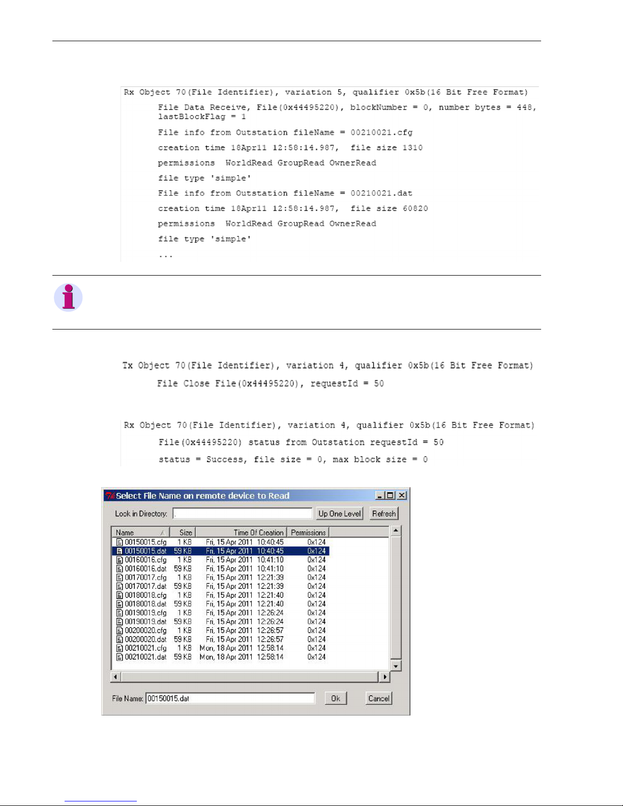
And interpret the response as file information (a read of a directory returns file directory information data):
Close the file using DNP3 IP object 70, var. 4 (close file), e.g.:
Which is confirmed with:
✧ In the DNP3 IP master the file selection after directory read could look like this:
Fig. 1-4 Select File Name on Remote Device to Read
NOTE
It can be seen here that for each fault record two files are available, a *.cfg and a *.dat, as it is usual for
Comtrade.
 Loading...