

Siemens Siprotec 7VK61 User Manual

SIPROTEC
Preface
Contents
Introduction 1
Functions 2
Breaker Management
Device
7VK61
V4.60
Manual
Mounting and Commissioning 3
Technical Data 4
Appendix A
Literature
Glossary
Index
C53000-G1176-C159-3

Note
For safety purposes, please note instructions and warnings in the Preface.
Disclaimer of liability
We have checked the text of this manual against the hardware and
software described. However, deviations from the description
cannot be completely ruled out, so that no liability can be accepted
for any errors or omissions contained in the information given.
The information given in this document is reviewed regularly and
any necessary corrections will be included in subsequent editions.
Copyright
Copyright © Siemens AG 2009. All rights reserved.
Dissemination or reproduction of this document, or evaluation and
communication of its contents, is not authorized except where expressly permitted. Violations are liable for damages. All rights reserved, particularly for the purposes of patent application or trademark registration.
We appreciate any suggestions for improvement.
We reserve the right to make technical improvements without
notice.
Document Version 4.11.00
Release date 05.2009
Registered Trademarks
SIPROTEC, SINAUT , SICAM and DIGSI are registered trademarks
of Siemens AG. Other designations in this manual might be trademarks whose use by third parties for their own purposes would infringe the rights of the owner.
Siemens Aktiengesellschaft Order no.: C53000-G1176-C159-3

Preface
Purpose of this Manual
This manual describes the functions, operation, installation, and commissioning of devices 7VK61. In particular,
one will find:
• Information regarding the configuration of the scope of the device and a description of the device functions
and settings → Chapter 2;
• Instructions for Installation and Commissioning → Chapter 3;
• Compilation of the Technical Data → Chapter 4;
• As well as a compilation of the most significant data for advanced users → Appendix A.
General information with regard to design, configuration, and operation of SIPROTEC 4 devices are set out in
the SIPROTEC 4 System Description /1/.
T arget Audience
Protection engineers, commissioning engineers, personnel concerned with adjustment, checking, and service
of selective protective equipment, automatic and control facilities, and personnel of electrical facilities and
power plants.
Applicability of this Manual
This manual applies to: SIPROTEC 4 Breaker Management Device 7VK61; firmware version V4.60.
Conformity Declaration
This product complies with the directive of the Council of the European Communities on the
approximation of the laws of the Member States relating to electromagnetic compatibility (EMC
Council Directive 89/336/EEC) and concerning electrical equipment for use within specified
voltage limits (Low-voltage Directive 73/23 EEC).
This conformity has been established by means of tests conducted by Siemens AG in accordance with Article 10 of the Council Directive in agreement with the generic standards EN
61000-6-2 and EN 61000-6-4 for the EMC directive, and with the standard EN 60255-6 for the
low-voltage directive.
The device has been designed and produced for industrial use.
The product conforms with the international standards of the series IEC 60255 and the German
standard VDE 0435.
Additional Standards IEEE Std C37.90-*
SIPROTEC, 7VK61, Manual
C53000-G1176-C159-3, Release date 05.2009
3
Preface
Additional Support
Should further information on the System SIPROTEC 4 be desired or should particular problems arise which
are not covered sufficiently for the purchaser's purpose, the matter should be referred to the local Siemens representative.
Our Customer Support Center provides a 24-hour service.
Phone: +49 (0180) 524-7000
Fax: +49 (0180) 524-2471
e-mail: support.energy@siemens.com
Training Courses
Enquiries regarding individual training courses should be addressed to our Training Center:
Siemens AG
Power Transmission and Distribution
Siemens Power Academy TD
Humboldt Street 59
90459 Nuremberg
Telephone: +49 (0911) 433-7005
Fax: +49 (0911) 433-7929
Internet: www.ptd-training.de
Safety Information
This manual does not constitute a complete index of all required safety measures for operation of the equipment (module, device), as special operational conditions may require additional measures. However, it comprises important information that should be noted for purposes of personal safety as well as avoiding material
damage. Information that is highlighted by means of a warning triangle and according to the degree of danger,
is illustrated as follows.
DANGER!
Danger indicates that death, severe personal injury or substantial material damage will result if proper precautions are not taken.
WARNING!
indicates that death, severe personal injury or substantial property damage may result if proper precautions are
not taken.
Caution!
indicates that minor personal injury or property damage may result if proper precautions are not taken. This
particularly applies to damage to or within th e device itself and consequential damage thereof.
4
C53000-G1176-C159-3, Release date 05.2009
SIPROTEC, 7VK61, Manual

Preface
Note
indicates information on the device, handling of the device, or the respective part of the instruction manual
which is important to be noted.
WARNING!
Qualified Personnel
Commissioning and operation of the equipment (module, device) as set out in this manual may only be carried
out by qualified personnel. Qualified personnel in terms of the technical safety information as set ou t in this
manual are persons who are authorized to commission, activate, to ground and to designate devices, systems
and electrical circuits in accordance with the safety standards.
Use as prescribed
The operational equipment (device, module) may only be used for such applications as set out in the catalogue
and the technical description, and only in combination with third-party equipment recommended or approved
by Siemens.
The successful and safe operation of the device is dependent on proper handling, storage, installation, operation, and maintenance.
When operating an electrical equipment, certain parts of the device are inevitably subject to dangerous voltage.
Severe personal injury or property damage may result if the device is not handled properly.
Before any connections are made, the device must be grounded to the ground terminal.
All circuit components connected to the voltage supply may be subject to dangerous voltage.
Dangerous voltage may be present in the device even after the power supply voltage has been removed (ca-
pacitors can still be charged).
Operational equipment with open circuited current transformer circuits may not be operated.
The limit values as specified in this manual or in the operating instructions may not be exceeded. This aspect
must also be observed during testing and commissioning.
SIPROTEC, 7VK61, Manual
C53000-G1176-C159-3, Release date 05.2009
5
Preface
Typographic and Symbol Conventions
The following text formats are used when literal information from the device or to the device appear in the text
flow:
Parameter Names
Designators of configuration or function parameters which may appear word-for-word in the display of the
device or on the screen of a personal computer (with operation software DIGSI), are marked in bold letters in
monospace type style. The same applies to the titles of menus.
1234A
Parameter addresses have the same character style as parameter names. Parameter addresses contain the
suffix A in the overview tables if the parameter can only be set in DIGSI via the option Display additional set-
tings.
Parameter Options
Possible settings of text parameters, which may appear word-for-word in the display of the device or on the
screen of a personal computer (with operation software DIGSI), are additionally written in italics. The same
applies to the options of the menus.
„Messages“
Designators for information, which may be output by the relay or required from other devices or from the switch
gear, are marked in a monospace type style in quotation marks.
Deviations may be permitted in drawings and tables when the type of designator can be obviously derived from
the illustration.
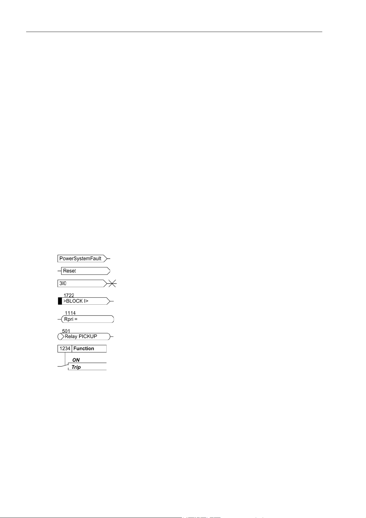
The following symbols are used in drawings:
Device-internal logical input signal
Device-internal logical output signal
Internal input signal of an analog quantity
External binary input signal with number (binary input,
input indication)
External binary output signal with number
(example of a value indication)
External binary output signal with number (device indication) used as
input signal
Example of a parameter switch designated FUNCTION with address
1234 and the possible settings ON and OFF
6
C53000-G1176-C159-3, Release date 05.2009
SIPROTEC, 7VK61, Manual
Preface
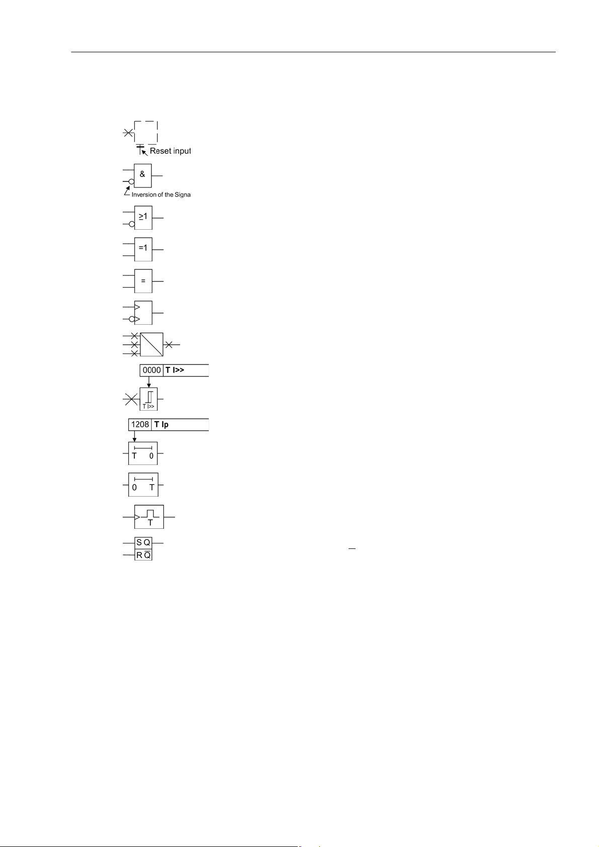
Besides these, graphical symbols are used in accordance with IEC 60617-12 and IEC 60617-13 or similar.
Some of the most frequently used are listed below:
analog input values
AND-gate operation of input values
OR-gate operation of input values
Exclusive OR gate (antivalence): output is active, if only one of the
inputs is active
Coincidence gate: output is active, if both inputs are active or inactive
at the same time
Dynamic inputs (edge-triggered) above with positive, below with negative edge
Formation of one analog output signal from a number of analog input
signals
Limit stage with setting address and parameter designator (name)
Timer (pickup delay T, example adjustable) with setting address and
parameter designator (name)
Timer (dropout delay T, example non-adjustable)
Dynamic triggered pulse timer T (monoflop)
Static memory (RS-flipflop) with setting input (S), resetting input (R),
output (Q) and inverted output (Q
)
■
SIPROTEC, 7VK61, Manual
C53000-G1176-C159-3, Release date 05.2009
7

Preface
8
C53000-G1176-C159-3, Release date 05.2009
SIPROTEC, 7VK61, Manual

Contents
1 Introduction. . . . . . . . . . . . . . . . . . . . . . . . . . . . . . . . . . . . . . . . . . . . . . . . . . . . . . . . . . . . . . . . . . . . . . . . . . . . . .15
1.1 Overall Operation. . . . . . . . . . . . . . . . . . . . . . . . . . . . . . . . . . . . . . . . . . . . . . . . . . . . . . . . . . . . . . . . . .16
1.2 Application Scope . . . . . . . . . . . . . . . . . . . . . . . . . . . . . . . . . . . . . . . . . . . . . . . . . . . . . . . . . . . . . . . . .18
1.3 Characteristics. . . . . . . . . . . . . . . . . . . . . . . . . . . . . . . . . . . . . . . . . . . . . . . . . . . . . . . . . . . . . . . . . . . .20
2 Functions. . . . . . . . . . . . . . . . . . . . . . . . . . . . . . . . . . . . . . . . . . . . . . . . . . . . . . . . . . . . . . . . . . . . . . . . . . . . . . . .23
2.1 General . . . . . . . . . . . . . . . . . . . . . . . . . . . . . . . . . . . . . . . . . . . . . . . . . . . . . . . . . . . . . . . . . . . . . . . .24
2.1.1 Functional Scope . . . . . . . . . . . . . . . . . . . . . . . . . . . . . . . . . . . . . . . . . . . . . . . . . . . . . . . . . . . . . . .24
2.1.1.1 Configuration of the Scope of Functions . . . . . . . . . . . . . . . . . . . . . . . . . . . . . . . . . . . . . . . . . .24
2.1.1.2 Setting Notes . . . . . . . . . . . . . . . . . . . . . . . . . . . . . . . . . . . . . . . . . . . . . . . . . . . . . . . . . . . . . . .24
2.1.1.3 Settings . . . . . . . . . . . . . . . . . . . . . . . . . . . . . . . . . . . . . . . . . . . . . . . . . . . . . . . . . . . . . . . . . . .26
2.1.2 Device . . . . . . . . . . . . . . . . . . . . . . . . . . . . . . . . . . . . . . . . . . . . . . . . . . . . . . . . . . . . . . . . . . . . . . .27
2.1.2.1 Trip-Dependent Indications . . . . . . . . . . . . . . . . . . . . . . . . . . . . . . . . . . . . . . . . . . . . . . . . . . . .27
2.1.2.2 Setting Notes . . . . . . . . . . . . . . . . . . . . . . . . . . . . . . . . . . . . . . . . . . . . . . . . . . . . . . . . . . . . . . .27
2.1.2.3 Settings . . . . . . . . . . . . . . . . . . . . . . . . . . . . . . . . . . . . . . . . . . . . . . . . . . . . . . . . . . . . . . . . . . .28
2.1.2.4 Information List. . . . . . . . . . . . . . . . . . . . . . . . . . . . . . . . . . . . . . . . . . . . . . . . . . . . . . . . . . . . . .28
2.1.3 Power System Data 1 . . . . . . . . . . . . . . . . . . . . . . . . . . . . . . . . . . . . . . . . . . . . . . . . . . . . . . . . . . .30
2.1.3.1 Setting Notes . . . . . . . . . . . . . . . . . . . . . . . . . . . . . . . . . . . . . . . . . . . . . . . . . . . . . . . . . . . . . . .30
2.1.3.2 Settings . . . . . . . . . . . . . . . . . . . . . . . . . . . . . . . . . . . . . . . . . . . . . . . . . . . . . . . . . . . . . . . . . . .34
2.1.4 Change Group . . . . . . . . . . . . . . . . . . . . . . . . . . . . . . . . . . . . . . . . . . . . . . . . . . . . . . . . . . . . . . . . .35
2.1.4.1 Purpose of the Setting Groups. . . . . . . . . . . . . . . . . . . . . . . . . . . . . . . . . . . . . . . . . . . . . . . . . .35
2.1.4.2 Setting Notes . . . . . . . . . . . . . . . . . . . . . . . . . . . . . . . . . . . . . . . . . . . . . . . . . . . . . . . . . . . . . . .35
2.1.4.3 Settings . . . . . . . . . . . . . . . . . . . . . . . . . . . . . . . . . . . . . . . . . . . . . . . . . . . . . . . . . . . . . . . . . . .36
2.1.4.4 Information List. . . . . . . . . . . . . . . . . . . . . . . . . . . . . . . . . . . . . . . . . . . . . . . . . . . . . . . . . . . . . .36
2.1.5 Power System Data 2 . . . . . . . . . . . . . . . . . . . . . . . . . . . . . . . . . . . . . . . . . . . . . . . . . . . . . . . . . . .36
2.1.5.1 Setting Notes . . . . . . . . . . . . . . . . . . . . . . . . . . . . . . . . . . . . . . . . . . . . . . . . . . . . . . . . . . . . . . .36
2.1.5.2 Settings . . . . . . . . . . . . . . . . . . . . . . . . . . . . . . . . . . . . . . . . . . . . . . . . . . . . . . . . . . . . . . . . . . .38
2.1.5.3 Information List. . . . . . . . . . . . . . . . . . . . . . . . . . . . . . . . . . . . . . . . . . . . . . . . . . . . . . . . . . . . . .38
2.1.6 Oscillographic Fault Records. . . . . . . . . . . . . . . . . . . . . . . . . . . . . . . . . . . . . . . . . . . . . . . . . . . . . .40
2.1.6.1 Description . . . . . . . . . . . . . . . . . . . . . . . . . . . . . . . . . . . . . . . . . . . . . . . . . . . . . . . . . . . . . . . . .40
2.1.6.2 Setting Notes . . . . . . . . . . . . . . . . . . . . . . . . . . . . . . . . . . . . . . . . . . . . . . . . . . . . . . . . . . . . . . .40
2.1.6.3 Settings . . . . . . . . . . . . . . . . . . . . . . . . . . . . . . . . . . . . . . . . . . . . . . . . . . . . . . . . . . . . . . . . . . .41
2.1.6.4 Information List. . . . . . . . . . . . . . . . . . . . . . . . . . . . . . . . . . . . . . . . . . . . . . . . . . . . . . . . . . . . . .41
2.1.7 Ethernet EN100-Module. . . . . . . . . . . . . . . . . . . . . . . . . . . . . . . . . . . . . . . . . . . . . . . . . . . . . . . . . .42
2.1.7.1 Function Description. . . . . . . . . . . . . . . . . . . . . . . . . . . . . . . . . . . . . . . . . . . . . . . . . . . . . . . . . .42
2.1.7.2 Setting Notes . . . . . . . . . . . . . . . . . . . . . . . . . . . . . . . . . . . . . . . . . . . . . . . . . . . . . . . . . . . . . . .42
2.1.7.3 Information List. . . . . . . . . . . . . . . . . . . . . . . . . . . . . . . . . . . . . . . . . . . . . . . . . . . . . . . . . . . . . .42
2.2 Automatic reclosure function (optional) . . . . . . . . . . . . . . . . . . . . . . . . . . . . . . . . . . . . . . . . . . . . . . . . .43
2.2.1 Function Description . . . . . . . . . . . . . . . . . . . . . . . . . . . . . . . . . . . . . . . . . . . . . . . . . . . . . . . . . . . .43
2.2.2 Setting Notes . . . . . . . . . . . . . . . . . . . . . . . . . . . . . . . . . . . . . . . . . . . . . . . . . . . . . . . . . . . . . . . . . .55
2.2.3 Settings . . . . . . . . . . . . . . . . . . . . . . . . . . . . . . . . . . . . . . . . . . . . . . . . . . . . . . . . . . . . . . . . . . . . . .62
2.2.4 Information List. . . . . . . . . . . . . . . . . . . . . . . . . . . . . . . . . . . . . . . . . . . . . . . . . . . . . . . . . . . . . . . . .65
SIPROTEC, 7VK61, Manual
C53000-G1176-C159-3, Release date 05.2009
9

Contents
2.3 Overcurrent protection (optional) . . . . . . . . . . . . . . . . . . . . . . . . . . . . . . . . . . . . . . . . . . . . . . . . . . . . .67
2.3.1 General . . . . . . . . . . . . . . . . . . . . . . . . . . . . . . . . . . . . . . . . . . . . . . . . . . . . . . . . . . . . . . . . . . . . . .67
2.3.2 Functional Description. . . . . . . . . . . . . . . . . . . . . . . . . . . . . . . . . . . . . . . . . . . . . . . . . . . . . . . . . . .67
2.3.3 Setting Notes. . . . . . . . . . . . . . . . . . . . . . . . . . . . . . . . . . . . . . . . . . . . . . . . . . . . . . . . . . . . . . . . . .73
2.3.4 Settings . . . . . . . . . . . . . . . . . . . . . . . . . . . . . . . . . . . . . . . . . . . . . . . . . . . . . . . . . . . . . . . . . . . . . .78
2.3.5 Information List . . . . . . . . . . . . . . . . . . . . . . . . . . . . . . . . . . . . . . . . . . . . . . . . . . . . . . . . . . . . . . . .80
2.4 Synchronism and voltage check (optional) . . . . . . . . . . . . . . . . . . . . . . . . . . . . . . . . . . . . . . . . . . . . . .81
2.4.1 Functional Description. . . . . . . . . . . . . . . . . . . . . . . . . . . . . . . . . . . . . . . . . . . . . . . . . . . . . . . . . . .81
2.4.2 Setting Notes. . . . . . . . . . . . . . . . . . . . . . . . . . . . . . . . . . . . . . . . . . . . . . . . . . . . . . . . . . . . . . . . . .87
2.4.3 Settings . . . . . . . . . . . . . . . . . . . . . . . . . . . . . . . . . . . . . . . . . . . . . . . . . . . . . . . . . . . . . . . . . . . . . .93
2.4.4 Information List . . . . . . . . . . . . . . . . . . . . . . . . . . . . . . . . . . . . . . . . . . . . . . . . . . . . . . . . . . . . . . . .94
2.5 Under and over-voltage protection (optional) . . . . . . . . . . . . . . . . . . . . . . . . . . . . . . . . . . . . . . . . . . . .96
2.5.1 Overvoltage Protection . . . . . . . . . . . . . . . . . . . . . . . . . . . . . . . . . . . . . . . . . . . . . . . . . . . . . . . . . .96
2.5.2 Undervoltage protection . . . . . . . . . . . . . . . . . . . . . . . . . . . . . . . . . . . . . . . . . . . . . . . . . . . . . . . . 102
2.5.3 Setting Notes. . . . . . . . . . . . . . . . . . . . . . . . . . . . . . . . . . . . . . . . . . . . . . . . . . . . . . . . . . . . . . . . .106
2.5.4 Settings . . . . . . . . . . . . . . . . . . . . . . . . . . . . . . . . . . . . . . . . . . . . . . . . . . . . . . . . . . . . . . . . . . . . .109
2.5.5 Information List . . . . . . . . . . . . . . . . . . . . . . . . . . . . . . . . . . . . . . . . . . . . . . . . . . . . . . . . . . . . . . . 111
2.6 Circuit breaker failure protection (optional). . . . . . . . . . . . . . . . . . . . . . . . . . . . . . . . . . . . . . . . . . . . . 114
2.6.1 Method of Operation . . . . . . . . . . . . . . . . . . . . . . . . . . . . . . . . . . . . . . . . . . . . . . . . . . . . . . . . . . . 114
2.6.2 Setting Notes. . . . . . . . . . . . . . . . . . . . . . . . . . . . . . . . . . . . . . . . . . . . . . . . . . . . . . . . . . . . . . . . .126
2.6.3 Settings . . . . . . . . . . . . . . . . . . . . . . . . . . . . . . . . . . . . . . . . . . . . . . . . . . . . . . . . . . . . . . . . . . . . .129
2.6.4 Information List . . . . . . . . . . . . . . . . . . . . . . . . . . . . . . . . . . . . . . . . . . . . . . . . . . . . . . . . . . . . . . .130
2.7 Monitoring Function. . . . . . . . . . . . . . . . . . . . . . . . . . . . . . . . . . . . . . . . . . . . . . . . . . . . . . . . . . . . . . .131
2.7.1 Measurement Supervision. . . . . . . . . . . . . . . . . . . . . . . . . . . . . . . . . . . . . . . . . . . . . . . . . . . . . . .131
2.7.1.1 Hardware Monitoring . . . . . . . . . . . . . . . . . . . . . . . . . . . . . . . . . . . . . . . . . . . . . . . . . . . . . . . . 131
2.7.1.2 Software Monitoring. . . . . . . . . . . . . . . . . . . . . . . . . . . . . . . . . . . . . . . . . . . . . . . . . . . . . . . . . 133
2.7.1.3 Monitoring External Transformer Circuits . . . . . . . . . . . . . . . . . . . . . . . . . . . . . . . . . . . . . . . .133
2.7.1.4 Monitoring the Phase Angle of the Positive Sequence Power . . . . . . . . . . . . . . . . . . . . . . . . . 138
2.7.1.5 Malfunction Reaction . . . . . . . . . . . . . . . . . . . . . . . . . . . . . . . . . . . . . . . . . . . . . . . . . . . . . . . 141
2.7.1.6 Setting Notes. . . . . . . . . . . . . . . . . . . . . . . . . . . . . . . . . . . . . . . . . . . . . . . . . . . . . . . . . . . . . . 143
2.7.1.7 Settings . . . . . . . . . . . . . . . . . . . . . . . . . . . . . . . . . . . . . . . . . . . . . . . . . . . . . . . . . . . . . . . . . .144
2.7.1.8 Information List . . . . . . . . . . . . . . . . . . . . . . . . . . . . . . . . . . . . . . . . . . . . . . . . . . . . . . . . . . . .145
2.7.2 Trip circuit supervision. . . . . . . . . . . . . . . . . . . . . . . . . . . . . . . . . . . . . . . . . . . . . . . . . . . . . . . . . .145
2.7.2.1 Functional Description. . . . . . . . . . . . . . . . . . . . . . . . . . . . . . . . . . . . . . . . . . . . . . . . . . . . . . . 145
2.7.2.2 Setting Notes. . . . . . . . . . . . . . . . . . . . . . . . . . . . . . . . . . . . . . . . . . . . . . . . . . . . . . . . . . . . . . 148
2.7.2.3 Settings . . . . . . . . . . . . . . . . . . . . . . . . . . . . . . . . . . . . . . . . . . . . . . . . . . . . . . . . . . . . . . . . . .149
2.7.2.4 Information List . . . . . . . . . . . . . . . . . . . . . . . . . . . . . . . . . . . . . . . . . . . . . . . . . . . . . . . . . . . .149
2.8 Function Control . . . . . . . . . . . . . . . . . . . . . . . . . . . . . . . . . . . . . . . . . . . . . . . . . . . . . . . . . . . . . . . . 150
2.8.1 General . . . . . . . . . . . . . . . . . . . . . . . . . . . . . . . . . . . . . . . . . . . . . . . . . . . . . . . . . . . . . . . . . . . . .150
2.8.1.1 Line energisation recognition. . . . . . . . . . . . . . . . . . . . . . . . . . . . . . . . . . . . . . . . . . . . . . . . . . 150
2.8.1.2 Detection of the Circuit Breaker Position. . . . . . . . . . . . . . . . . . . . . . . . . . . . . . . . . . . . . . . . .152
2.8.1.3 Open Pole Detector. . . . . . . . . . . . . . . . . . . . . . . . . . . . . . . . . . . . . . . . . . . . . . . . . . . . . . . . . 154
2.8.1.4 Pickup Logic of the Entire Device . . . . . . . . . . . . . . . . . . . . . . . . . . . . . . . . . . . . . . . . . . . . . .156
2.8.1.5 Tripping Logic of the Entire Device . . . . . . . . . . . . . . . . . . . . . . . . . . . . . . . . . . . . . . . . . . . . . 157
2.8.1.6 Setting Notes. . . . . . . . . . . . . . . . . . . . . . . . . . . . . . . . . . . . . . . . . . . . . . . . . . . . . . . . . . . . . . 161
2.8.2 Circuit breaker trip test . . . . . . . . . . . . . . . . . . . . . . . . . . . . . . . . . . . . . . . . . . . . . . . . . . . . . . . . .161
2.8.2.1 Functional Description. . . . . . . . . . . . . . . . . . . . . . . . . . . . . . . . . . . . . . . . . . . . . . . . . . . . . . . 161
2.8.2.2 Information List . . . . . . . . . . . . . . . . . . . . . . . . . . . . . . . . . . . . . . . . . . . . . . . . . . . . . . . . . . . .162
10
C53000-G1176-C159-3, Release date 05.2009
SIPROTEC, 7VK61, Manual

Contents
2.9 Auxiliary Functions . . . . . . . . . . . . . . . . . . . . . . . . . . . . . . . . . . . . . . . . . . . . . . . . . . . . . . . . . . . . . . .163
2.9.1 Message Processing . . . . . . . . . . . . . . . . . . . . . . . . . . . . . . . . . . . . . . . . . . . . . . . . . . . . . . . . . . .163
2.9.1.1 Method of Operation. . . . . . . . . . . . . . . . . . . . . . . . . . . . . . . . . . . . . . . . . . . . . . . . . . . . . . . . .163
2.9.2 Statistics. . . . . . . . . . . . . . . . . . . . . . . . . . . . . . . . . . . . . . . . . . . . . . . . . . . . . . . . . . . . . . . . . . . . .166
2.9.2.1 Function Description. . . . . . . . . . . . . . . . . . . . . . . . . . . . . . . . . . . . . . . . . . . . . . . . . . . . . . . . .166
2.9.2.2 Setting Notes . . . . . . . . . . . . . . . . . . . . . . . . . . . . . . . . . . . . . . . . . . . . . . . . . . . . . . . . . . . . . .167
2.9.2.3 Information List. . . . . . . . . . . . . . . . . . . . . . . . . . . . . . . . . . . . . . . . . . . . . . . . . . . . . . . . . . . . .167
2.9.3 Measurement. . . . . . . . . . . . . . . . . . . . . . . . . . . . . . . . . . . . . . . . . . . . . . . . . . . . . . . . . . . . . . . . .167
2.9.3.1 Functional Description . . . . . . . . . . . . . . . . . . . . . . . . . . . . . . . . . . . . . . . . . . . . . . . . . . . . . . .167
2.9.3.2 Information List. . . . . . . . . . . . . . . . . . . . . . . . . . . . . . . . . . . . . . . . . . . . . . . . . . . . . . . . . . . . .169
2.9.4 Energy . . . . . . . . . . . . . . . . . . . . . . . . . . . . . . . . . . . . . . . . . . . . . . . . . . . . . . . . . . . . . . . . . . . . . .170
2.9.4.1 Energy Metering. . . . . . . . . . . . . . . . . . . . . . . . . . . . . . . . . . . . . . . . . . . . . . . . . . . . . . . . . . . .170
2.9.4.2 Setting Notes . . . . . . . . . . . . . . . . . . . . . . . . . . . . . . . . . . . . . . . . . . . . . . . . . . . . . . . . . . . . . .170
2.9.4.3 Information List. . . . . . . . . . . . . . . . . . . . . . . . . . . . . . . . . . . . . . . . . . . . . . . . . . . . . . . . . . . . .170
2.10 Command Processing . . . . . . . . . . . . . . . . . . . . . . . . . . . . . . . . . . . . . . . . . . . . . . . . . . . . . . . . . . . .171
2.10.1 Control Authorization . . . . . . . . . . . . . . . . . . . . . . . . . . . . . . . . . . . . . . . . . . . . . . . . . . . . . . . . . . .171
2.10.1.1 Type of Commands . . . . . . . . . . . . . . . . . . . . . . . . . . . . . . . . . . . . . . . . . . . . . . . . . . . . . . . . .171
2.10.1.2 Sequence in the Command Path . . . . . . . . . . . . . . . . . . . . . . . . . . . . . . . . . . . . . . . . . . . . . .172
2.10.1.3 Interlocking . . . . . . . . . . . . . . . . . . . . . . . . . . . . . . . . . . . . . . . . . . . . . . . . . . . . . . . . . . . . . . .173
2.10.1.4 Information List. . . . . . . . . . . . . . . . . . . . . . . . . . . . . . . . . . . . . . . . . . . . . . . . . . . . . . . . . . . . .175
2.10.2 Control Device . . . . . . . . . . . . . . . . . . . . . . . . . . . . . . . . . . . . . . . . . . . . . . . . . . . . . . . . . . . . . . . .175
2.10.2.1 Description . . . . . . . . . . . . . . . . . . . . . . . . . . . . . . . . . . . . . . . . . . . . . . . . . . . . . . . . . . . . . . . .176
2.10.2.2 Information List. . . . . . . . . . . . . . . . . . . . . . . . . . . . . . . . . . . . . . . . . . . . . . . . . . . . . . . . . . . . .176
2.10.3 Process Data . . . . . . . . . . . . . . . . . . . . . . . . . . . . . . . . . . . . . . . . . . . . . . . . . . . . . . . . . . . . . . . . .177
2.10.3.1 Method of Operation. . . . . . . . . . . . . . . . . . . . . . . . . . . . . . . . . . . . . . . . . . . . . . . . . . . . . . . . .177
2.10.3.2 Information List. . . . . . . . . . . . . . . . . . . . . . . . . . . . . . . . . . . . . . . . . . . . . . . . . . . . . . . . . . . . .178
2.10.4 Protocol . . . . . . . . . . . . . . . . . . . . . . . . . . . . . . . . . . . . . . . . . . . . . . . . . . . . . . . . . . . . . . . . . . . . .178
2.10.4.1 Information List. . . . . . . . . . . . . . . . . . . . . . . . . . . . . . . . . . . . . . . . . . . . . . . . . . . . . . . . . . . . .178
3 Mounting and Commissioning . . . . . . . . . . . . . . . . . . . . . . . . . . . . . . . . . . . . . . . . . . . . . . . . . . . . . . . . . . . . .179
3.1 Mounting and Connections . . . . . . . . . . . . . . . . . . . . . . . . . . . . . . . . . . . . . . . . . . . . . . . . . . . . . . . . .180
3.1.1 Configuration Information. . . . . . . . . . . . . . . . . . . . . . . . . . . . . . . . . . . . . . . . . . . . . . . . . . . . . . . .180
3.1.2 Hardware Modifications . . . . . . . . . . . . . . . . . . . . . . . . . . . . . . . . . . . . . . . . . . . . . . . . . . . . . . . . .184
3.1.2.1 General. . . . . . . . . . . . . . . . . . . . . . . . . . . . . . . . . . . . . . . . . . . . . . . . . . . . . . . . . . . . . . . . . . .184
3.1.2.2 Disassembly. . . . . . . . . . . . . . . . . . . . . . . . . . . . . . . . . . . . . . . . . . . . . . . . . . . . . . . . . . . . . . .186
3.1.2.3 Switching Elements on Printed Circuit Boards. . . . . . . . . . . . . . . . . . . . . . . . . . . . . . . . . . . . .188
3.1.2.4 Interface Modules. . . . . . . . . . . . . . . . . . . . . . . . . . . . . . . . . . . . . . . . . . . . . . . . . . . . . . . . . . .199
3.1.2.5 Reassembly . . . . . . . . . . . . . . . . . . . . . . . . . . . . . . . . . . . . . . . . . . . . . . . . . . . . . . . . . . . . . . .202
3.1.3 Mounting . . . . . . . . . . . . . . . . . . . . . . . . . . . . . . . . . . . . . . . . . . . . . . . . . . . . . . . . . . . . . . . . . . . .203
3.1.3.1 Panel Flush Mounting . . . . . . . . . . . . . . . . . . . . . . . . . . . . . . . . . . . . . . . . . . . . . . . . . . . . . . .203
3.1.3.2 Rack and Cubicle Mounting . . . . . . . . . . . . . . . . . . . . . . . . . . . . . . . . . . . . . . . . . . . . . . . . . .204
3.1.3.3 Panel Mounting . . . . . . . . . . . . . . . . . . . . . . . . . . . . . . . . . . . . . . . . . . . . . . . . . . . . . . . . . . . .206
3.2 Checking Connections . . . . . . . . . . . . . . . . . . . . . . . . . . . . . . . . . . . . . . . . . . . . . . . . . . . . . . . . . . . . .207
3.2.1 Checking Data Connections of Serial Interfaces . . . . . . . . . . . . . . . . . . . . . . . . . . . . . . . . . . . . . .207
3.2.2 Checking the System Connections . . . . . . . . . . . . . . . . . . . . . . . . . . . . . . . . . . . . . . . . . . . . . . . .210
SIPROTEC, 7VK61, Manual
C53000-G1176-C159-3, Release date 05.2009
11

Contents
3.3 Commissioning . . . . . . . . . . . . . . . . . . . . . . . . . . . . . . . . . . . . . . . . . . . . . . . . . . . . . . . . . . . . . . . . . .212
3.3.1 Test Mode / Transmission Block . . . . . . . . . . . . . . . . . . . . . . . . . . . . . . . . . . . . . . . . . . . . . . . . . . 213
3.3.2 Test Time Synchronisation Interface . . . . . . . . . . . . . . . . . . . . . . . . . . . . . . . . . . . . . . . . . . . . . . .213
3.3.3 Testing the System Interface. . . . . . . . . . . . . . . . . . . . . . . . . . . . . . . . . . . . . . . . . . . . . . . . . . . . .214
3.3.4 Checking the switching states of the binary Inputs/Outputs . . . . . . . . . . . . . . . . . . . . . . . . . . . . .216
3.3.5 Checking for Breaker Failure Protection . . . . . . . . . . . . . . . . . . . . . . . . . . . . . . . . . . . . . . . . . . . .218
3.3.6 Current, Voltage, and Phase Rotation Testing. . . . . . . . . . . . . . . . . . . . . . . . . . . . . . . . . . . . . . . .220
3.3.7 Directional Check with Load Current . . . . . . . . . . . . . . . . . . . . . . . . . . . . . . . . . . . . . . . . . . . . . .221
3.3.8 Polarity Check for the Voltage Input U
3.3.9 Polarity check for the current input I
. . . . . . . . . . . . . . . . . . . . . . . . . . . . . . . . . . . . . . . . . . . . .222
4
. . . . . . . . . . . . . . . . . . . . . . . . . . . . . . . . . . . . . . . . . . . . . .224
4
3.3.10 Measuring the Operating Time of the Circuit Breaker. . . . . . . . . . . . . . . . . . . . . . . . . . . . . . . . . .224
3.3.11 Check of the Signal Transmission for Breaker Failure Protection and/or End Fault Protection . .225
3.3.12 Testing User-defined Functions. . . . . . . . . . . . . . . . . . . . . . . . . . . . . . . . . . . . . . . . . . . . . . . . . . .225
3.3.13 Trip and Close Test with the Circuit Breaker . . . . . . . . . . . . . . . . . . . . . . . . . . . . . . . . . . . . . . . . . 225
3.3.14 Switching Test of the Configured Operating Equipment . . . . . . . . . . . . . . . . . . . . . . . . . . . . . . . .226
3.3.15 Triggering Oscillographic Recording for Test. . . . . . . . . . . . . . . . . . . . . . . . . . . . . . . . . . . . . . . . .226
3.4 Final Preparation of the Device . . . . . . . . . . . . . . . . . . . . . . . . . . . . . . . . . . . . . . . . . . . . . . . . . . . . .228
4 Technical Data . . . . . . . . . . . . . . . . . . . . . . . . . . . . . . . . . . . . . . . . . . . . . . . . . . . . . . . . . . . . . . . . . . . . . . . . . .229
4.1 General . . . . . . . . . . . . . . . . . . . . . . . . . . . . . . . . . . . . . . . . . . . . . . . . . . . . . . . . . . . . . . . . . . . . . . . . 230
4.1.1 Analogue Inputs and Outputs . . . . . . . . . . . . . . . . . . . . . . . . . . . . . . . . . . . . . . . . . . . . . . . . . . . .230
4.1.2 Auxiliary voltage . . . . . . . . . . . . . . . . . . . . . . . . . . . . . . . . . . . . . . . . . . . . . . . . . . . . . . . . . . . . . . 230
4.1.3 Binary Inputs and Outputs . . . . . . . . . . . . . . . . . . . . . . . . . . . . . . . . . . . . . . . . . . . . . . . . . . . . . .231
4.1.4 Communication Interfaces . . . . . . . . . . . . . . . . . . . . . . . . . . . . . . . . . . . . . . . . . . . . . . . . . . . . . .232
4.1.5 Electrical Tests. . . . . . . . . . . . . . . . . . . . . . . . . . . . . . . . . . . . . . . . . . . . . . . . . . . . . . . . . . . . . . . . 236
4.1.6 Mechanical Tests. . . . . . . . . . . . . . . . . . . . . . . . . . . . . . . . . . . . . . . . . . . . . . . . . . . . . . . . . . . . . .237
4.1.7 Climatic Stress Tests . . . . . . . . . . . . . . . . . . . . . . . . . . . . . . . . . . . . . . . . . . . . . . . . . . . . . . . . .238
4.1.8 Deployment Conditions . . . . . . . . . . . . . . . . . . . . . . . . . . . . . . . . . . . . . . . . . . . . . . . . . . . . . . . . 239
4.1.9 Construction . . . . . . . . . . . . . . . . . . . . . . . . . . . . . . . . . . . . . . . . . . . . . . . . . . . . . . . . . . . . . . . 239
4.2 Automatic Reclosure (optional). . . . . . . . . . . . . . . . . . . . . . . . . . . . . . . . . . . . . . . . . . . . . . . . . . . . . .240
4.3 Time Overcurrent Protection. . . . . . . . . . . . . . . . . . . . . . . . . . . . . . . . . . . . . . . . . . . . . . . . . . . . . . . .241
4.4 Synchronism and Voltage Check (optional) . . . . . . . . . . . . . . . . . . . . . . . . . . . . . . . . . . . . . . . . . . . . 248
4.5 Voltage Protection (optional) . . . . . . . . . . . . . . . . . . . . . . . . . . . . . . . . . . . . . . . . . . . . . . . . . . . . . .250
4.6 Circuit Breaker Failure Protection (optional). . . . . . . . . . . . . . . . . . . . . . . . . . . . . . . . . . . . . . . . . . . .253
4.7 Monitoring Functions. . . . . . . . . . . . . . . . . . . . . . . . . . . . . . . . . . . . . . . . . . . . . . . . . . . . . . . . . . . . . .254
4.8 User Defined Functions (CFC) . . . . . . . . . . . . . . . . . . . . . . . . . . . . . . . . . . . . . . . . . . . . . . . . . . .256
4.9 Auxiliary Functions . . . . . . . . . . . . . . . . . . . . . . . . . . . . . . . . . . . . . . . . . . . . . . . . . . . . . . . . . . . . . . 260
4.10 Dimensions . . . . . . . . . . . . . . . . . . . . . . . . . . . . . . . . . . . . . . . . . . . . . . . . . . . . . . . . . . . . . . . . . . . . .262
1
4.10.1 Panel Flush Mounting or Cubicle Mounting (housing size
4.10.2 Panel flush mounting or cubicle installation (housing size
1
4.10.3 Panel surface mounting (housing size
4.10.4 Panel surface mounting (housing size
/3) . . . . . . . . . . . . . . . . . . . . . . . . . . . . . . . . . . . . . . .264
1
/2) . . . . . . . . . . . . . . . . . . . . . . . . . . . . . . . . . . . . . . . . . .264
/3) . . . . . . . . . . . . . . . . . . . . . . . . . . . 262
1
/2) . . . . . . . . . . . . . . . . . . . .263
12
C53000-G1176-C159-3, Release date 05.2009
SIPROTEC, 7VK61, Manual

Contents
A Appendix . . . . . . . . . . . . . . . . . . . . . . . . . . . . . . . . . . . . . . . . . . . . . . . . . . . . . . . . . . . . . . . . . . . . . . . . . . . . . . .265
A.1 Ordering Information and Accessories . . . . . . . . . . . . . . . . . . . . . . . . . . . . . . . . . . . . . . . . . . . . . . . .266
A.1.1 Ordering Information . . . . . . . . . . . . . . . . . . . . . . . . . . . . . . . . . . . . . . . . . . . . . . . . . . . . . . . . . . . 266
A.1.1.1 Ordering Code (MLFB) . . . . . . . . . . . . . . . . . . . . . . . . . . . . . . . . . . . . . . . . . . . . . . . . . . . . .266
A.1.2 Accessories . . . . . . . . . . . . . . . . . . . . . . . . . . . . . . . . . . . . . . . . . . . . . . . . . . . . . . . . . . . . . . . . . .268
A.2 Terminal Assignments . . . . . . . . . . . . . . . . . . . . . . . . . . . . . . . . . . . . . . . . . . . . . . . . . . . . . . . . . . . . .271
A.2.1 Housing for Panel Flush or Cubicle Mounting . . . . . . . . . . . . . . . . . . . . . . . . . . . . . . . . . .271
A.2.2 Housing for Panel Surface Mounting . . . . . . . . . . . . . . . . . . . . . . . . . . . . . . . . . . . . . . . . . . . . . . .273
A.3 Connection Examples . . . . . . . . . . . . . . . . . . . . . . . . . . . . . . . . . . . . . . . . . . . . . . . . . . . . . . . . . . . . .275
A.3.1 Current Transformer Connection Examples. . . . . . . . . . . . . . . . . . . . . . . . . . . . . . . . . . . . . . . . . .275
A.3.2 Voltage Transformer Connection Examples. . . . . . . . . . . . . . . . . . . . . . . . . . . . . . . . . . . . . . . . . .276
A.4 Default Settings . . . . . . . . . . . . . . . . . . . . . . . . . . . . . . . . . . . . . . . . . . . . . . . . . . . . . . . . . . . . . . . . . .279
A.4.1 LEDs . . . . . . . . . . . . . . . . . . . . . . . . . . . . . . . . . . . . . . . . . . . . . . . . . . . . . . . . . . . . . . . . . . . . . . .279
A.4.2 Binary Input . . . . . . . . . . . . . . . . . . . . . . . . . . . . . . . . . . . . . . . . . . . . . . . . . . . . . . . . . . . . . . . . . .279
A.4.3 Binary Output. . . . . . . . . . . . . . . . . . . . . . . . . . . . . . . . . . . . . . . . . . . . . . . . . . . . . . . . . . . . . . . . .281
A.4.4 Function Keys . . . . . . . . . . . . . . . . . . . . . . . . . . . . . . . . . . . . . . . . . . . . . . . . . . . . . . . . . . . . . . . .281
A.4.5 Default Display. . . . . . . . . . . . . . . . . . . . . . . . . . . . . . . . . . . . . . . . . . . . . . . . . . . . . . . . . . . . . . . .282
A.4.6 Pre-defined CFC Charts. . . . . . . . . . . . . . . . . . . . . . . . . . . . . . . . . . . . . . . . . . . . . . . . . . . . . . . . .283
A.5 Protocol-dependent Functions. . . . . . . . . . . . . . . . . . . . . . . . . . . . . . . . . . . . . . . . . . . . . . . . . . . . . . .284
A.6 Functional Scope. . . . . . . . . . . . . . . . . . . . . . . . . . . . . . . . . . . . . . . . . . . . . . . . . . . . . . . . . . . . . . . . .285
A.7 Settings . . . . . . . . . . . . . . . . . . . . . . . . . . . . . . . . . . . . . . . . . . . . . . . . . . . . . . . . . . . . . . . . . . . . . . . .286
A.8 Information List . . . . . . . . . . . . . . . . . . . . . . . . . . . . . . . . . . . . . . . . . . . . . . . . . . . . . . . . . . . . . . . . . .294
A.9 Group Alarms. . . . . . . . . . . . . . . . . . . . . . . . . . . . . . . . . . . . . . . . . . . . . . . . . . . . . . . . . . . . . . . . . . . .312
A.10 Measured Values. . . . . . . . . . . . . . . . . . . . . . . . . . . . . . . . . . . . . . . . . . . . . . . . . . . . . . . . . . . . . . . . .313
Literature. . . . . . . . . . . . . . . . . . . . . . . . . . . . . . . . . . . . . . . . . . . . . . . . . . . . . . . . . . . . . . . . . . . . . . . . . . . . . . .315
Glossary . . . . . . . . . . . . . . . . . . . . . . . . . . . . . . . . . . . . . . . . . . . . . . . . . . . . . . . . . . . . . . . . . . . . . . . . . . . . . . .317
Index . . . . . . . . . . . . . . . . . . . . . . . . . . . . . . . . . . . . . . . . . . . . . . . . . . . . . . . . . . . . . . . . . . . . . . . . . . . . . . . . . .329
SIPROTEC, 7VK61, Manual
C53000-G1176-C159-3, Release date 05.2009
13

Contents
14
C53000-G1176-C159-3, Release date 05.2009
SIPROTEC, 7VK61, Manual

Introduction 1
The SIPROTEC 4 7VK61 is introduced in this chapter. The device is presented in its application, characteristics, and functional scope.
1.1 Overall Operation 16
1.2 Application Scope 18
1.3 Characteristics 20
SIPROTEC, 7VK61, Manual
C53000-G1176-C159-3, Release date 05.2009
15
Introduction
1.1 Overall Operation
1.1 Overall Operation
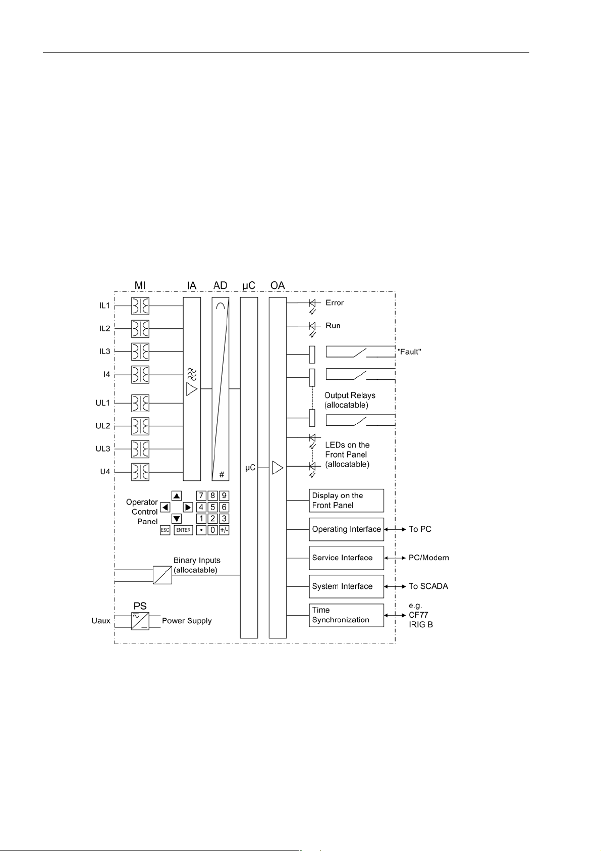
The digital breaker management relay SIPROTEC 4 7VK61 is equipped with a powerful microprocessor
system. All tasks are processed fully digitally , from the acquisition of measured values up to sending commands
to the circuit breakers. Figure 1-1 shows the basic structure of the 7VK61.
Analog Inputs
The measuring inputs (MI) transform the currents and voltages from the instrument transformers and match
them to the internal signal levels for processing in the device. The device has 4 current inputs and 4 voltage
inputs. Three current inputs are provided for measuring the phase currents, a further measuring input (I
be configured to detect the earth current (CT starpoint) or a separate earth current transformer. The analog
input quantities are passed on to the input amplifiers (IA).
) can
4
16
Figure 1-1 Hardware structure of the Breaker Management Device 7VK61
A voltage measuring input is provided for each phase-earth voltage. A further voltage input (U
) may be select-
4
ed to measure either the displacement voltage, for the additional voltage of synchronism and voltage check or
for any other voltage U
(for overvoltage protection). The analogue values are transferred to the IA input am-
X
plifier group.
The input amplifier group IA provides high-resistance termination for the analog input quantities. It consists of
filters that are optimized for measured value processing with regard to bandwidth and processing speed.
C53000-G1176-C159-3, Release date 05.2009
SIPROTEC, 7VK61, Manual

The AD analog-to-digital converter group contains analog/digital converters and memory chips for data transfer
to the microcomputer system.
Microcomputer System
Apart from processing the measured values, the microcomputer system µC also executes the actual protection
and control functions. They especially consist of:
• Filtering and conditioning of the measured signals
• Continuous monitoring of the measured quantities
• Monitoring of the pickup conditions for the individual protective functions
• Querying of limit values and time sequences
• Control of signals for logical functions
• Reaching trip and close command decisions
• Stocking messages, fault data and fault values for fault analysis purposes
• Administration of the operating system and its functions, e.g. data storage, realtime clock, communication,
interfaces, etc.
The information is provided via output amplifier OA.
Introduction
1.1 Overall Operation
Binary Inputs and Outputs
Binary inputs and outputs from and to the computer system are routed via the I/O modules (inputs and outputs).
The “µC” issues information to external equipment via the output contacts. Outputs are mainly commands that
are issued to the switching devices and messages for remote signalling of events and states.
Front Elements
LEDs and an LC display provide information on the function of the device and indicate events, states and measured values.
Integrated control and numeric keys in conjunction with the LCD facilitate local interaction with the local device.
All information of the device can be accessed using the integrated control and numeric keys. This information
includes protective and control settings, operating and fault indications, and measured values; setting parameters can be changed (see also Chapter 2 and SIPROTEC 4 System Description).
Serial Interfaces
Via the serial operator interface
ating program DIGSI is possible. This facilitates a comfortable handling of all device functions.
The service interface
pecially well suited for the central interrogation of the devices from a PC or for remote operation via a modem.
All device data can be transmitted to a central evaluating unit or control center through the serial system
(SCADA) interface. This interface may be provided with various physical transmission modes and different protocols to suit the particular application.
in the front panel the communication with a personal computer using the oper-
can also be used for communication with a personal computer using DIGSI. This is es-
A further interface is provided for time synchronization
sources.
Further communication protocols can be realized via additional interface modules.
Power Supply
These described functional units are supplied by a power supply PS with the necessary power in the different
voltage levels. Brief supply voltage dips which may occur on short circuits in the auxiliary voltage supply of the
power system are usually bridged by a capacitor (see also Technical Data, Subsection 4.1).
SIPROTEC, 7VK61, Manual
C53000-G1176-C159-3, Release date 05.2009
of the internal clock through external synchronization
17

Introduction
1.2 Application Scope
1.2 Application Scope
The 7VK61 breaker management relay is a multi-purpose starting and control device for automatic and manual
closing of circuit breakers in electrical networks of all voltage levels.
The automatic reclose function may be used on overhead lines for single-pole, three-pole or single- and threepole automatic reclosure as well as multi-shot automatic reclosure. The adaptive dead times can be set individually for single-pole, three-pole auto-reclosure and for additional (up to 8) reclose cycles.
Before reclosure after three-pole tripping, the validity of the reclosure can be checked by synchronism check
by the device (can be ordered optionally). Alternatively, the de-energization of the line or of the busbar can be
checked. If desired, asynchronous energization is also possible. In this case, the device calculates the moment
of the energization command so that the two voltages at busbar and feeder are in phase the instant the circuitbreaker poles make contact.
The circuit breaker must be suitable for auto-reclosing. For single-pole auto-reclosure the poles must be individually controllable. The device considers whether the circuit breaker is ready for a trip and close cycle and its
position - provided this information is supplied by the circuit breaker. The breaker recovery time can be monitored. During single-pole auto-reclosure the relay can either process the parallel connection or the series connection or both connections of the auxiliary contacts at the circuit breaker poles. The relay is furthermore
capable of processing the auxiliary contact of each pole. But generally the relay can operate without such information from the circuit breaker.
7VK61 can work together with static and digital protection equipment requiring only pickup and trip operations
from them. For single-pole auto-reclosure the trip signals must either be distinguished as to whether they are
single-pole or three pole or they must be transmitted to the relay for each pole separately . In the event of threepole auto-reclosure alone a general trip signal is sufficient.
Protective Functions
The 7VK61 features the following basic functions:
• Automatic Reclosure Function
• Synchronism and Voltage Check
• Circuit Breaker Failure Protection
• Voltage Protection
• Time Overcurrent Protection
Control Functions
The device is equipped with control functions which operate, close and open, switchgear via function keys, the
system interface, binary inputs and from a PC with the DIGSI software. The status of the primary equipment
can be transmitted to the device via auxiliary contacts connected to binary inputs. The present status (or position) of the primary equipment can be displayed on the device, and used for interlocking or plausibility monitoring. The number of the devices to be switched is limited by the binary inputs and outputs available in the device
or the binary inputs and outputs allocated for the switch position feedbacks. Depending on the primary equipment being controlled, one binary input (single point indication) or two binary inputs (double point indication)
may be used for this process. The switching of primary equipment can be restricted by corresponding settings
of the switching authority (Remote or Local), and by the operating mode (interlocked/non-interlocked, with or
without password request). Interlocking conditions for switching (e.g. switchgear interlocking) can be established using the integrated user-defined logic.
18
C53000-G1176-C159-3, Release date 05.2009
SIPROTEC, 7VK61, Manual

Indications and Measured Values; Fault Recording
The operational indications provide information about conditions in the power system and the device. Measurement quantities and values that are calculated can be displayed locally and communicated via the serial interfaces.
Indications can be assigned to a number of LEDs on the front panel (allocatable), can be externally processed
via output contacts (allocatable), linked with user-definable logic functions and/or issued via serial interfaces
(see Communication below).
During a fault (power system fault) important events and changes in conditions are saved in fault logs (Event
Log or Trip Log). Instantaneous fault values are also saved in the device and may be analyzed subsequently.
Communication
Serial interfaces are available for the communication with operating, control and memory systems.
A 9-pin DSUB socket on the front panel is used for local communication with a PC. The SIPROTEC 4 operating
software DIGSI allows users to carry out all operational and evaluation tasks via this operator
as specifying and modifying configuration parameters and settings, configuring user-specific logic functions,
retrieving operational messages and measured values, inquiring device conditions and measured values,
issuing control commands.
To establish an extensive communication with other digital operating, control and memory components the
device may be provided with further interfaces depending on the order variant.
Introduction
1.2 Application Scope
interface, such
The service interface
can be operated via the RS232 or RS485 interface and also allows communication via
modem. For this reason, remote operation is possible via PC and the DIGSI operating software, e.g. to operate
several devices via a central PC.
The system interface
ensures the central communication between the device and the substation controller. It
can be operated through the RS232, the RS485 or the fibre optic interface. Several standardized protocols are
available for data transmission. An EN 100 module allows to integrate the devices into 100 Mbit Ethernet communication networks used by process control and automation systems and running IEC 61850 protocols. In
parallel to the process control integration of the device, this interface can also be used for communication with
DIGSI and for inter-relay communication via GOOSE.
Another interface is provided for the tim e syn chronization
of the internal clock via external synchronization
sources (IRIG-B or DCF77).
SIPROTEC, 7VK61, Manual
C53000-G1176-C159-3, Release date 05.2009
19

Introduction
1.3 Characteristics
1.3 Characteristics
General Features
• Powerful 32-bit microprocessor system
• complete numerical processing of measured values and control, from sampling and digitalising of the analogue input values up to tripping commands to the circuit breakers
• complete galvanic and reliable separation between the internal processing circuits from the measurement,
control, and power supply circuits by analogue input transducers, binary inputs and outputs and the DC/DC
or AC voltage converters
• simple device operation using the integrated operator panel or a connected personal computer with operator
guidance
• simple device operation using the integrated operator panel or a connected personal computer with operator
guidance
Automatic Reclosure Function (optional)
• For reclosure after single-pole, three-pole or single-pole and three-pole tripping
• Single or multiple reclosure (up to 8 reclosure attempts)
• With separate action times for every reclosure attempt, optionally without action times
• With separate dead times after single-pole and three-pole tripping, separate for the first four reclosure attempts
• Controlled optionally by production pickup with separate dead times after single, two-pole and three-pole
pickup
• Optionally with adaptive dead time, reduced dead time and dead line check
Synchronism and Voltage Check (optional)
• Verification on the synchronous conditions before reclosing after three-pole tripping
• Fast measuring of voltage difference U
• Alternatively, check of the de-energized state before reclosing
• Closing at asynchronous system conditions with prediction of the synchronization time
• Settable minimum and maximum voltage
• Verification of the synchronous conditions or de-energized state also possible before the manual closing of
the circuit breaker, with separate limit values
• Phase angle compensation for voltage measurement behind a transformer
• Measuring voltages optionally phase-pase or phase-earth
, on the phase angle difference ϕ
diff
and frequency difference f
diff
diff
Time overcurrent protection (optional, available with breaker failure protection)
• Two definite time stages (DT) and one inverse time stage (IDMT), each for phase currents and earth current
• For inverse time overcurrent protection a selection from various characteristics based on several standards
is possible
• Blocking capability e.g. for reverse interlocking with any element
• Instantaneous tripping by any stage when switching onto a fault
20
C53000-G1176-C159-3, Release date 05.2009
SIPROTEC, 7VK61, Manual

• Additional stage, e.g. stub protection, for fast tripping of faults between the current transformer and line isolator (when the isolator switching status feedback is available); particularly suitable for substation with circuit
breaker arrangement 1
1
/
2
Circuit Breaker Failure Protection (optional)
• Start by external trip functions;
• Start by trip command of every internal protection function
• Single-stage or two-stage
• Short dropout and overshoot times
• Independent timers for single-pole and three-pole tripping;
• Short dropout and overshoot times
Voltage Protection (optional)
• Overvoltage and undervoltage detection with different stages
• Two overvoltage stages for the phase-earth voltages
• Two overvoltage stages for the phase-phase voltages
Introduction
1.3 Characteristics
• Two overvoltage stages for the positive sequence voltage, with a time delay each;
• Two overvoltage stages for the negative sequence voltage
• Two overvoltage stages for the zero sequence voltage or any other single-phase voltage
• Settable dropout to pickup ratios
• Two undervoltage stages for the phase-earth voltages
• Two undervoltage stages for the phase-phase voltages
• Two undervoltage stages for the positive sequence voltage
• Settable current criterion for undervoltage protection functions
User-defined Logic Functions (CFC)
• Freely programmable combination of internal and external signals for the implementation of user-defined
logic functions
• All usual logic functions
• Time delays and limit value inquiries
Command Processing
• Circuit breakers can be opened and closed manually via programmable function keys, via the system interface (e.g. SICAM or LSA), or via the operating interface (using a PC with DIGSI);
• Feedback on switching states via the circuit breaker auxiliary contacts (for commands with feedback)
• Plausibility monitoring of the circuit breaker position and monitoring of interlocking conditions for switching
operations
SIPROTEC, 7VK61, Manual
C53000-G1176-C159-3, Release date 05.2009
21

Introduction
1.3 Characteristics
Monitoring Functions
• Availability of the device is greatly increased because of self-monitoring of the internal measurement circuits,
power supply, hardware and software
• Monitoring of the current and voltage transformer secondary circuits by means of summation and symmetry
checks
• Trip circuit supervision
• Checking for the measured direction and the phase sequence.
Additional Functions
• Battery buffered real time clock, which may be synchronized via a synchronization signal (e.g. DCF77, IRIG
B via satellite receiver), binary input or system interface
• Continuous calculation and display of measured quantities on the front display;
• Fault event memory (trip log) for the last 8 network faults (faults in the power system), with real time stamps;
• Fault recording and data transfer for fault recording for a maximum time range of 15 s;
• Statistics: Counter with the trip commands issued by the device, as well as recording of the fault current data
and accumulation of the interrupted fault currents;
• Communication with central control and memory components possible via serial interfaces (depending on
the individual ordering variant), optionally via data line, modem or fibre optics;
• Commissioning aids such as connection checks as well as circuit breaker test functions.
■
22
C53000-G1176-C159-3, Release date 05.2009
SIPROTEC, 7VK61, Manual

Functions 2
This chapter describes the individual functions of the SIPROTEC 4 device 7VK61. It shows the setting possibilities for each function in maximum configuration. Guidelines for establishing setting values and, where required, formulae are given.
Based on the following information, it can also be determined which of the provided functions should be used.
2.1 General 24
2.2 Automatic reclosure function (optional) 43
2.3 Overcurrent protection (optional) 67
2.4 Synchronism and voltage check (optional) 81
2.5 Under and over-voltage protection (optional) 96
2.6 Circuit breaker failure protection (optional) 114
2.7 Monitoring Function 131
2.8 Function Control 150
2.9 Auxiliary Functions 163
2.10 Command Processing 171
SIPROTEC, 7VK61, Manual
C53000-G1176-C159-3, Release date 05.2009
23

Functions
2.1 General
2.1 General
A few seconds after the device is switched on, the initial display appears in the LCD. A selection of measured
values is displayed.
Configuration of the device functions are made via the DIGSI software from your PC. The procedure is described in detail in the SIPROTEC 4 System Description. Entry of password No. 7 (for setting modification) is
required to modify configuration settings. Without the password, the settings may be read, but may not be modified and transferred to the device.
The function parameters, i.e. settings of function options, threshold values, etc., can be entered via the keypad
and display on the front of the device, or by means of a personal computer connected to the front or service
interface of the device utilising the DIGSI software package. The level 5 password (individual parameters) is
required.
2.1.1 Functional Scope
2.1.1.1 Configuration of the Scope of Functions
The 7VK61 relay contains a series of protective and additional functions. The hardware and firmware provided
is designed for this scope of functions. In addition, the command functions can be matched to the system conditions. Individual functions can be activated or deactivated during the configuration procedure. The interaction
of functions may also be modified e.g., the reclosing function can be implemented with or without synchronisation. If a function is not required, it can be deactivated during configuration.
The available protection and supplementary functions can be configured as Enabled or Disabled. For some
functions, a choice may be presented between several options which are explained below.
Functions configured as Disabled are not processed by the 7VK61. There are no indications, and corresponding settings (functions, limit values) are not displayed during setting.
Note
The functions and default settings available depend on the order variant of the device.
2.1.1.2 Setting Notes
Configuring the functional scope
The scope of functions with the available options is set in the Functional Scope dialog box to match plant requirements.
Most settings are self-explanatory. The special cases
are described below.
Special Cases
If use of the setting group changeover function is desired, address 103 Grp Chge OPTION should be set to
Enabled. In this case, up to four different groups of settings may be changed quickly and easily during device
operation (see also Section 2.1.4). With the setting Disabled only one parameter group is available.
Address 106 VT CONNECTION determines how the voltage transformers are connected. VT CONNECTION =
3phase implies that the three phase voltages are connected in wye connection. Select VT CONNECTION =
1phase if the device is connected to only one voltage transformer. In this case, the voltage connected to
24
C53000-G1176-C159-3, Release date 05.2009
SIPROTEC, 7VK61, Manual

Functions
2.1 General
voltage input U4 is always interpreted as the voltage U
which is to be synchronized. Parameter 210 U4
Sy2
transformer is then invariably set to Usy2 transf. and excludes other setting options. Parameter 212
Usy2 connection is then set to determine which primary voltage is connected. The setting VT CONNECTION
= NO hides all voltage-relevant functions and parameters.
Parameter 107 CT CONNECTION is set to configure the current transformer connection. If the default setting
CT CONNECTION = YES is active, all current-induced functions (current criterion of voltage protection, line
status detection, measurements of currents and power, current-induced measured value monitoring) are operational. The setting CT CONNECTION = NO allows the device to be operated without any current transformer
connection; all current-induced functions and parameters are then hidden.
Address 110 Trip mode is only valid for devices that can trip single-pole or three-pole. Set 1-/3pole to
enable also single-pole tripping, i.e. if you want to utilise single-pole or single-pole/three-pole automatic reclosure. This requires that an internal automatic reclosure function exists or that an external reclosing device is
used. Furthermore, the circuit breaker must be capable of single-pole tripping.
All functions are set to Disabled by default. This has no effect on the presetting of LEDs, binary inputs and
binary outputs.
Note
If you have changed address 110, save your changes first via OK and reopen the dialog box since the other
setting options depend on the selection in address 110.
If the device features an automatic reclosing function, address 133 and 134 are of importance. Automatic reclosure is only permitted for overhead lines. It must not be used in any other case. If the protected object consists of a combination of overhead lines and other equipment (e.g. overhead line in unit with a transformer or
overhead line/cable), reclosure is only permissible if it can be ensured that it can only take place in the event
of a fault on the overhead line. If no automatic reclosing function is desired for the feeder at which 7VK61 operates, or if an external device is used for reclosure, set address 133 Auto Reclose to Disabled.
Otherwise set the number of desired reclosing attempts there. Y ou can select 1 AR-cycle to 8 AR-cycles.
You can also set ADT (adaptive dead times); in this case the behaviour of the automatic reclosure function is
determined by the cycles of the remote end. The number of cycles must however be configured at least in one
of the line ends which must have a reliable infeed. The other end — or other ends, if there are more than two
line ends — may operate with adaptive dead time. Section 2.2 provides detailed information on this topic.
The AR control mode at address 134 allows a total of four options. On the one hand, it can be determined
whether the auto reclose cycles are carried out according to the fault type detected by the pickup of the starting
protective function(s) (only for three-pole tripping) or according to the type of trip command. On the other
hand, the automatic reclosure function can be operated with or without action time.
The setting Trip with T-action / Trip without T-action ... (default setting = With trip command
... ) is to be preferred if single-pole
or single-pole/three-pole auto reclose cycles are provided for and possible.
In this case, different dead times (for every AR cycle) are possible after single-pole tripping and after three-pole
tripping. The protective function that issues the trip command determines the type of trip: Single-pole or threepole. The dead time is controlled dependent on this.
The setting Pickup with T-action / Pickup without T-action ... is only possible and visible if only three-pole
tripping is desired i.e., if only three-pole tripping is configured (address 110 Trip mode = 3pole only, see
above). In this case you can set different dead times for the auto-reclose cycles following single-pole
and three-pole
faults. The decisive factor he re is the pickup situation of the protective functions at the instant
, two-pole
the trip command disappears. This control mode enables also the dead times to be made dependent on the
type of fault in the case of three-pole reclosure cycles. Tripping is always three-pole.
The setting Trip with T-action provides an action time for each reclose cycle. The action time is started
by a general pickup of all protective functions. If no trip command is present before the action time expires, the
corresponding reclose cycle is not carried out. Section 2.2 provides detailed information on this topic. This
setting is recommended for time-graded protection. If the protection function which is to operate with automatic
SIPROTEC, 7VK61, Manual
C53000-G1176-C159-3, Release date 05.2009
25

Functions
2.1 General
reclosure does not have a general pickup signal for starting the action times, select ... Trip without T-
action.
For the trip circuit supervision set at address 140 Trip Cir. Sup. the number of trip circuits to be monitored:
1 trip circuit, 2 trip circuits or 3 trip circuits, unless you omit it (Disabled).
2.1.1.3 Settings
Addr. Parameter Setting Options Default Setting Comments
103 Grp Chge OPTION Disabled
Enabled
106 VT CONNECTION 3phase
1phase
NO
107 CT CONNECTION YES
NO
110 Trip mode 3pole only
1-/3pole
126 Back-Up O/C Disabled
TOC IEC
TOC ANSI
TOC IEC /w 3ST
133 Auto Reclose 1 AR-cycle
2 AR-cycles
3 AR-cycles
4 AR-cycles
5 AR-cycles
6 AR-cycles
7 AR-cycles
8 AR-cycles
ADT
Disabled
134 AR control mode Pickup w/ Tact
Pickup w/o Tact
Trip w/ Tact
Trip w/o Tact
135 Synchro-Check Disabled
Enabled
137 U/O VOLTAGE Disabled
Enabled
139 BREAKER FAILURE Disabled
Enabled
enabled w/ 3I0>
140 Trip Cir. Sup. Disabled
1 trip circuit
2 trip circuits
3 trip circuits
Disabled Setting Group Change Option
3phase Voltage transformer connection
YES Current transformer connection
3pole only Trip mode
Disabled Backup overcurrent
Disabled Auto-Reclose Function
Trip w/ Tact Auto-Reclose control mode
Disabled Synchronism and Voltage Check
Disabled Under / Overvoltage Protection
Disabled Breaker Failure Protection
Disabled Trip Circuit Supervision
26
C53000-G1176-C159-3, Release date 05.2009
SIPROTEC, 7VK61, Manual
2.1.2 Device
The device requires some general information. This may be, for example, the type of indication to be issued in
the event a power system fault occurs.
2.1.2.1 Trip-Dependent Indications
The storing of indications masked to local LEDs, and the maintenance of spontaneous indications, can be
made dependent on whether the device has issued a trip signal. This information is then not output if one or
more protection functions have picked up during a system disturbance, but no tripping by the 7VK61 resulted
because the fault was cleared by a different device (e.g. on another line). These indications are then limited to
faults on the line to be protected.
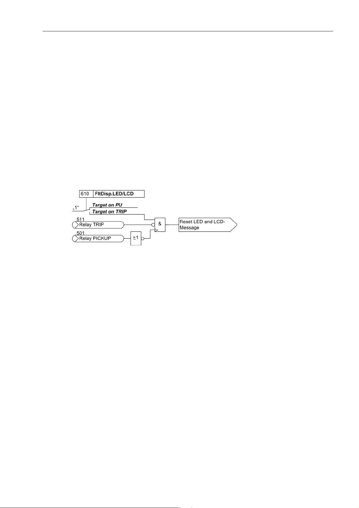
The figure below illustrates the generation of the reset command for stored indications. When the relay drops
off, stationary conditions (fault display on every pickup/on trip only; trip/no trip) decide whether the new fault
will be stored or reset.
Functions
2.1 General
Figure 2-1 Creation of the reset command for the latched LED and LCD messages
2.1.2.2 Setting Notes
Fault Annunciations
Pickup of a new protective function generally turns off any previously lit LEDs, so that only the latest fault is
displayed at any time. It can be selected whether the stored LED displays and the spontaneous indications on
the display appear upon renewed pickup, or only after a renewed trip signal is issued. In order to enter the
desired type of display, select the submenu Device in the SETTINGS menu. At address 610
FltDisp.LED/LCD the two alternatives Target on PU and Target on TRIP („No trip - no flag“) are of-
fered.
At address 625 T MIN LED HOLD you can specify a delay time (e.g. ) during which the LEDs will not be reset.
After this delay time has elapsed, the LEDs can be reset. All present information items are OR-combined.
After startup of the device featuring a 4-line display, measured values are displayed by default. Use the arrow
keys on the device front to select the different representations of the measured values for the so called default
display. The start page of the default display, which is displayed by default after startup of the device, can be
selected via parameter 640 Start image DD. The available representation types for the measured value are
listed in the appendix .
SIPROTEC, 7VK61, Manual
C53000-G1176-C159-3, Release date 05.2009
27

Functions
2.1 General
2.1.2.3 Settings
Addresses which have an appended "A" can only be changed with DIGSI, under Additional Settings.
Addr. Parameter Setting Options Default Setting Comments
610 FltDisp.LED/LCD Target on PU
Target on TRIP
625A T MIN LED HOLD 0 .. 60 min; ∞ 0 min Minimum hold time of lachted
Target on PU Fault Display on LED / LCD
LEDs
640 Start image DD image 1
image 2
image 3
image 4
image 5
image 6
image 1 Start image Default Display
2.1.2.4 Information List
No. Information Type of In-
formation
- Test mode IntSP Test mode
- DataStop IntSP Stop data transmission
- UnlockDT IntSP Unlock data transmission via BI
- Reset LED IntSP Reset LED
- SynchClock IntSP_Ev Clock Synchronization
- >Light on SP >Back Light on
- HWTestMod IntSP Hardware Test Mode
- Error FMS1 OUT Error FMS FO 1
- Error FMS2 OUT Error FMS FO 2
- Distur.CFC OUT Disturbance CFC
1 Not configured SP No Function configured
2 Non Existent SP Function Not Available
3 >Time Synch SP >Synchronize Internal Real Time Clock
5 > Reset LED SP >Reset LED
11 >Annunc. 1 SP >User defined annunciation 1
12 >Annunc. 2 SP >User defined annunciation 2
13 >Annunc. 3 SP >User defined annunciation 3
14 >Annunc. 4 SP >User defined annunciation 4
15 >Tes t mo de SP >Test mode
16 >DataStop SP >Stop data transmission
51 Device OK OUT Device is Operational and Protecting
52 ProtActive IntSP At Least 1 Protection Funct. is Active
55 Reset Device OUT Reset Device
56 Initial Start OUT Initial Start of Device
67 Resume OUT Resume
68 Clock SyncError OUT Clock Synchronization Error
69 DayLightSavTime OUT Daylight Saving Time
70 Settings Calc. OUT Setting calculation is running
Comments
28
C53000-G1176-C159-3, Release date 05.2009
SIPROTEC, 7VK61, Manual

Functions
2.1 General
No. Information Type of In-
Comments
formation
71 Settings Check OUT Settings Check
72 Level-2 change OUT Level-2 change
73 Local change OUT Local setting change
110 Event Lost OUT_Ev Event lost
113 Flag Lost OUT Flag Lost
125 Chatter ON OUT Chatter ON
126 ProtON/OFF IntSP Protection ON/OFF (via system port)
127 AR ON/OFF IntSP Auto Reclose ON/OFF (via system port)
140 Error Sum Alarm OUT Error with a summary alarm
144 Error 5V OUT Error 5V
160 Alarm Sum Event OUT Alarm Summary Event
177 Fail Battery OUT Failure: Battery empty
181 Error A/D-conv. OUT Error: A/D converter
183 Error Board 1 OUT Error Board 1
184 Error Board 2 OUT Error Board 2
185 Error Board 3 OUT Error Board 3
186 Error Board 4 OUT Error Board 4
187 Error Board 5 OUT Error Board 5
188 Error Board 6 OUT Error Board 6
189 Error Board 7 OUT Error Board 7
190 Error Board 0 OUT Error Board 0
191 Error Offset OUT Error: Offset
192 Error1A/5Awrong OUT Error:1A/5Ajumper different from setting
193 Alarm adjustm. OUT Alarm: Analog input adjustment invalid
194 Error neutralCT OUT Error: Neutral CT different from MLFB
320 Warn Mem. Data OUT Warn: Limit of Memory Data exceeded
321 Warn Mem. Para. OUT Warn: Limit of Memory Parameter exceeded
322 Warn Mem. Oper. OUT Warn: Limit of Memory Operation exceeded
323 Warn Mem. New OUT Warn: Limit of Memory New exceeded
SIPROTEC, 7VK61, Manual
C53000-G1176-C159-3, Release date 05.2009
29
Functions
2.1 General
2.1.3 Power System Data 1
The device requires some plant and power system data in order to be able to adapt its functions accordingly,
dependent on the actual application. The data required include for instance rated data of the substation and the
measuring transformers, polarity and connection of the measured quantities, if necessary features of the circuit
breakers, and others. Furthermore, there is a number of settings associated with several functions rather than
a specific protection, control or monitoring function. The Power System Data 1 can only be changed from a PC
running DIGSI and are discussed in this section.
2.1.3.1 Setting Notes
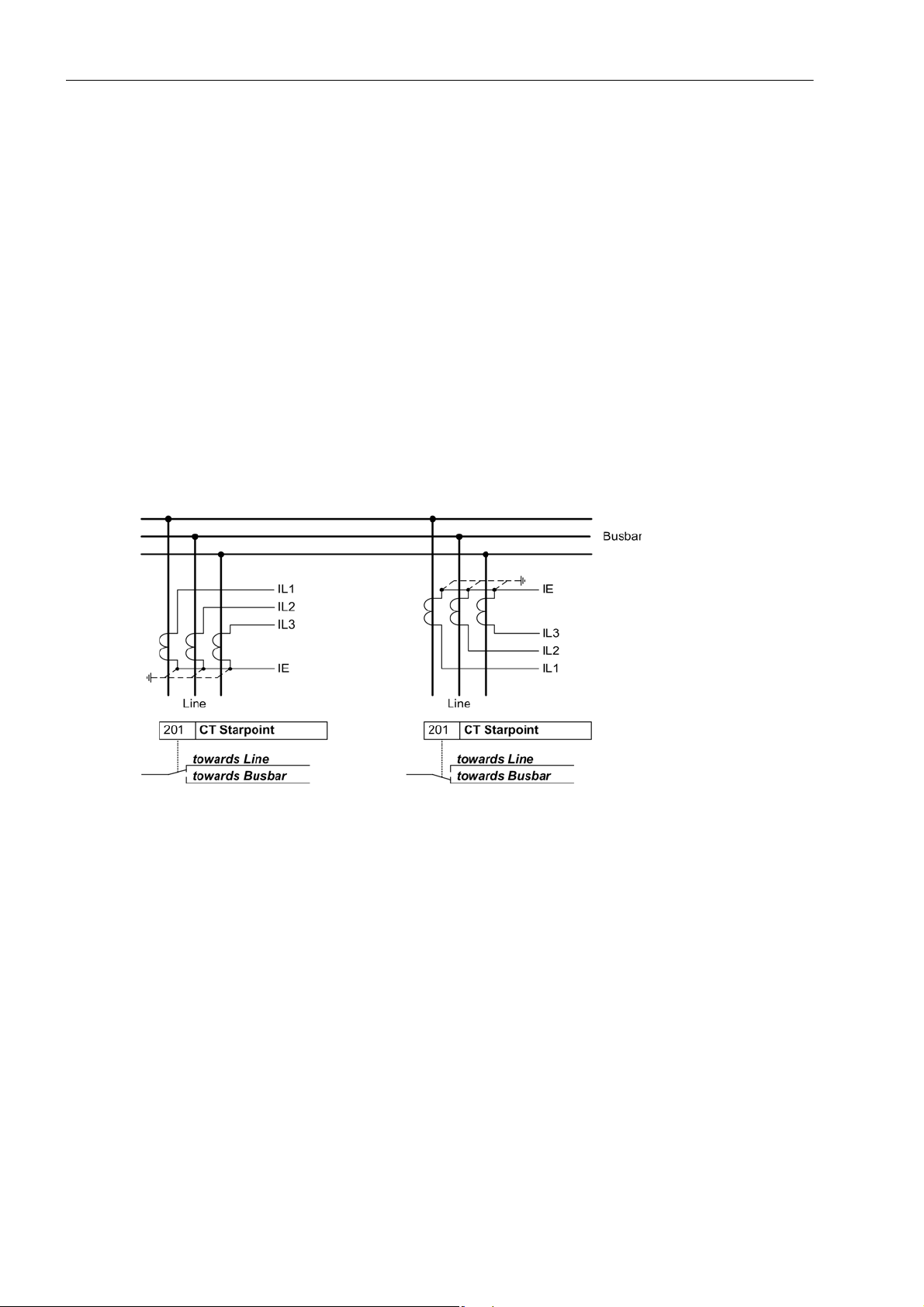
Current Transformer Polarity
At address 201 CT Starpoint, the polarity of the wye-connected current transformers is specified (the following figure applies accordingly to two current transformers). This setting determines the measuring direction
of the device (forward = line direction). A change in this setting also results in a polarity reversal of the earth
current inputsI
.
E
Figure 2-2 Polarity of current transformers
Nominal Values of the Transformers
In addresses 203 Unom PRIMARY and 204 Unom SECONDARY the device obtains information on the primary
and secondary rated voltage (phase-to-phase voltage) of the voltage transformers.
It is important to ensure that the secondary CT nominal current matches the rated current of the device, otherwise the device will incorrectly calculate primary data.
Correct entry of the primary data is a prerequisite for the correct computation of operational measured values
with primary magnitude. If the settings of the device are performed with primary values using DIGSI, these
primary data are an indispensable requirement for the correct function of the device.
30
C53000-G1176-C159-3, Release date 05.2009
SIPROTEC, 7VK61, Manual
 Loading...