

Siemens Siprotec 7UM611, Siprotec 7UM612 User Manual

SIPROTEC
www . ElectricalPartManuals . com
Preface
Introduction 1
Functions 2
Mounting and Commissioning 3
Multi-Functional Generator
Protection Relay
7UM61
V4.1
Manual
Technical Data 4
Appendix A
Literature
Glossary
Index
C53000-G1176-C127-3

Disclaimer of liability
www . ElectricalPartManuals . com
We have checked the text of this manual against the hardware
and software described. However, deviations from the description cannot be completely ruled out, so that no liability can be accepted for any errors or omissions contained in the information
given.
The information in this manual is checked periodically, and necessary corrections will be included in future editions. We appreciate any suggested improvements.
We reserve the right to make technical improvements without
notice.
Copyright
Copyright © Siemens AG 2003. All rights reserved.
Dissemination or reproduction of this document, or evaluation
and communication of its contents, is not authorized except
where expressly permitted. Violations are liable for damages. All
rights reserved, particularly for the purposes of patent application
or trademark registration.
Registered Trademarks
SIPROTEC, SINAUT, SICAM and DIGSI are registered trademarks of SIEMENS AG. Other designations in this manual may
be trademarks that if used by third parties for their own purposes
may violate the rights of the owner.
4.10.05
7UM61 Manual
C53000-G1176-C127-3
Preface
www . ElectricalPartManuals . com
Purpose of this Manual
Target Audience Protection engineers, commissioning engineers, personnel concerned with adjust-
Applicability of this Manual
Indication of Conformity
This manual describes the functions, operation, installation, and commissioning of the
device 7UM61. In particular it contains:
• Information regarding the configuration of the device extent and descriptions of
device functions and settings → Chapter 2;
• Instructions for mounting and commissioning → Chapter 3;
• Compilation of technical data→ Chapter 4;
• As well as a compilation of the most significant data for experienced users in Appendix A.
®
General information about design, configuration, and operation of SIPROTEC
devices is laid down in the SIPROTEC
ment, checking, and service of selective protective equipment, automatic and control
facilities, and personnel of electrical facilities and power plants.
This manual is valid for: Multi-Functional Generator Protection Relay with Local
Control SIPROTEC
This product complies with the directive of the Council of the European Communities on the approximation of the laws of the Member States relating to electromagnetic compatibility (EMC Council Directive 89/336/EEC) and concerning electrical equipment for use within specified voltage limits (Low-voltage directive 73/23
EEC).
This conformity has been proved by tests conducted by Siemens AG in accordance with Article 10 of the Council Directive in agreement with the generic standards EN 50081 and EN 61000-6-2 (for EMC directive) and the standard
EN 60255-6 (for low-voltage directive). This device was designed and produced
for industrial use according to the EMC standard.
The product conforms with the international standard of the series IEC 60255 and
the German standard VDE 0435.
®
4 7UM61; firmware version V4.1.
®
System Description /1/.
4
This product is UL-certified according to the Technical Data:
C53000-G1176-C127-3
37UM61 Manual
Preface
www . ElectricalPartManuals . com
Additional Support Should further information on the System SIPROTEC® 4 be desired or should partic-
ular problems arise which are not covered sufficiently for the purchaser's purpose, the
matter should be referred to the local Siemens representative.
Training Courses Individual course offerings may be found in our Training Catalogue, or questions may
be directed to our training centre in Nuremberg.
Instructions and
Warnings
The warnings and notes contained in this manual serve for your own safety and for
an appropriate lifetime of the device. Please observe them!
The following indicators and standard definitions are used:
DANGER
indicates that death, severe personal injury or substantial property damage will
result if proper precautions are not taken.
Warning
indicates that death, severe personal injury or substantial property damage can
result if proper precautions are not taken.
Caution
indicates that minor personal injury or property damage can result if proper precautions are not taken. This particularly applies to damage on or in the device itself and
consequential damage thereof.
Note
indicates information about the device or respective part of the instruction manual
which is essential to highlight.
WARNING!
When operating an electrical device, certain parts of the device inevitably have dangerous voltages.
Failure to observe these precautions can result in fatality, personal injury, or extensive
material damage.
Only qualified personnel shall work on and around this equipment. It must be thoroughly familiar with all warnings and safety notices of this manual as well as with the
applicable safety regulations.
The successful and safe operation of this device is dependent on proper handling, installation, operation, and maintenance by qualified personnel under observance of all
warnings and hints contained in this manual. In particular the general erection and
safety regulations (e.g. IEC, DIN, VDE, EN or other national and international standards) regarding the correct use of hoisting gear must be observed.
4
7UM61 Manual
C53000-G1176-C127-3
Definition QUALIFIED PERSONNEL
www . ElectricalPartManuals . com
For the purpose of this instruction manual and product labels, a qualified person is
one who is familiar with the installation, construction and operation of the equipment
and the hazards involved. In addition, he has the following qualifications:
• Is trained and authorized to energize, de-energize, clear, ground and tag circuits
and equipment in accordance with established safety practices.
• Is trained in the proper care and use of protective equipment in accordance with
established safety practices.
• Is trained in rendering first aid.
Typographic and
Graphical Conventions
To designate terms which refer in the text to information of the device or for the
device, the following fonts are used:
Parameter names
Designators of configuration or function parameters which may appear word-forword in the display of the device or on the screen of a personal computer (with operation software DIGSI
also applies to header bars for selection menus.
1234A
Parameter addresses have the same character style as parameter names. Parameter addresses contain the suffix A in the overview tables if the parameter can only
be set in DIGSI
Parameter Conditions
Possible settings of text parameters, which may appear word-for-word in the
display of the device or on the screen of a personal computer (with operation software DIGSI
selection menus.
“Annunciations”
Designators for information, which may be output by the relay or required from other
devices or from the switch gear, are marked in a monospace type style in quotation
marks.
®
), are additionally written in italics. This also applies to header bars for
®
®
via the option Display additional settings.
Preface
), are marked in bold letters of a monospace type style. This
7UM61 Manual
C53000-G1176-C127-3
Deviations may be permitted in drawings and tables when the type of designator can
be obviously derived from the illustration.
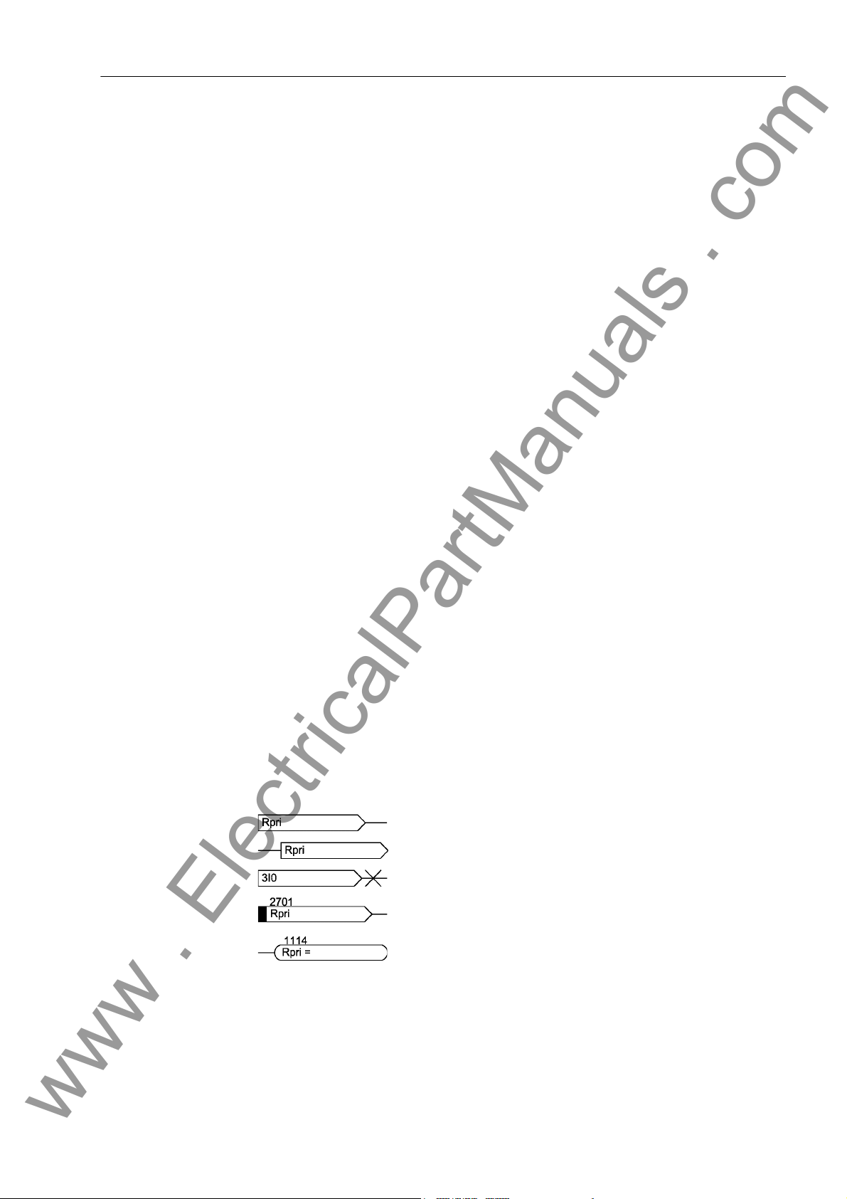
The following symbols are used in drawings:
Device-internal logical input signal
Device-internal (logical) output signal
Internal input signal of an analog quantity
External binary input signal with number (binary input, input
indication)
External binary output signal with number (device indication)
5
Preface
www . ElectricalPartManuals . com
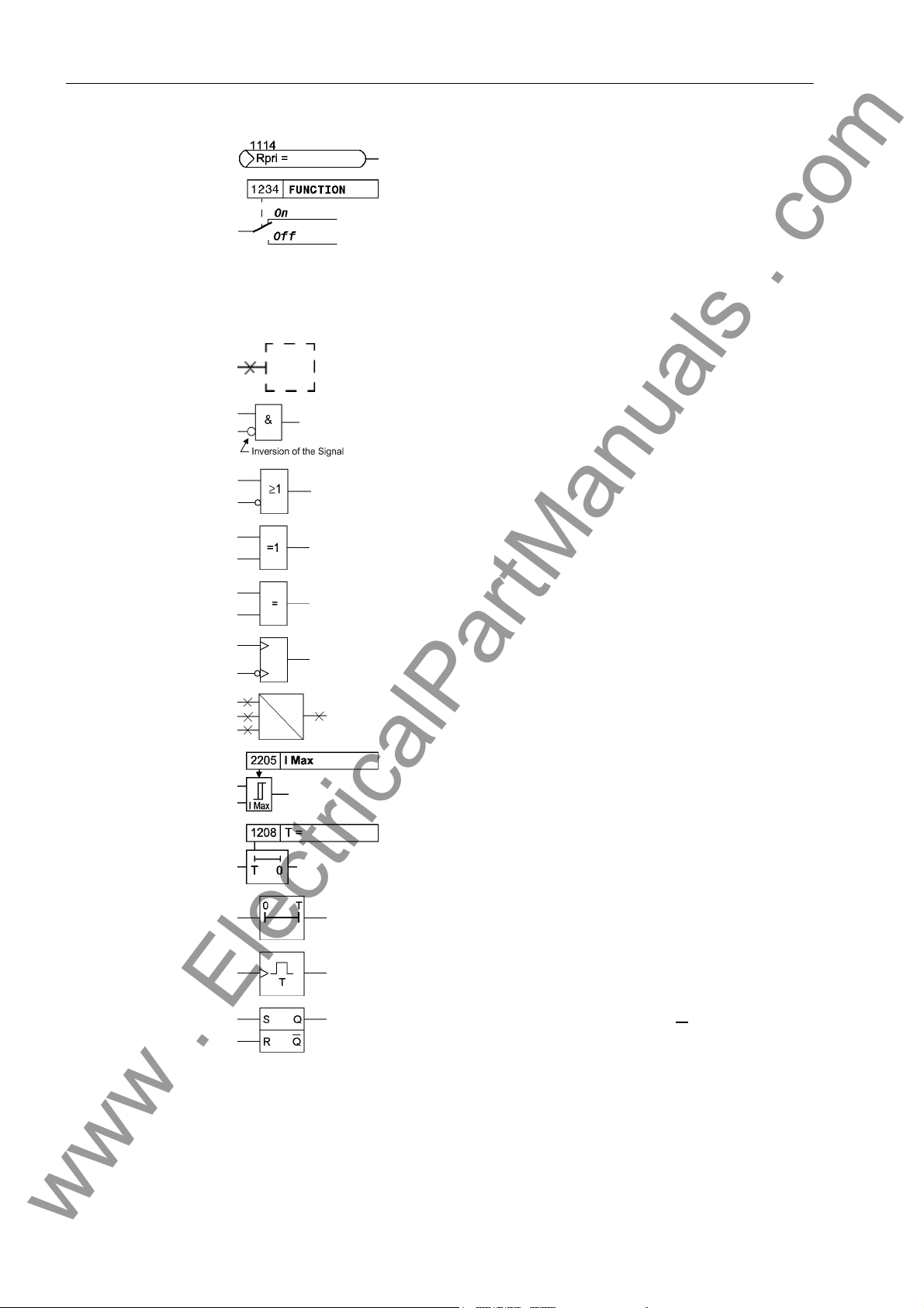
External binary output signal with number (device indication)
used as input signal
Example of a parameter switch designated FUNCTION with
the address 1234 and the possible settings ON and OFF
Besides these, graphical symbols are used according to IEC 60617-12 and IEC
60617-13 or symbols derived from these standards. Some of the most frequently used
are listed below:
Input signal of an analog quantity
AND gate
OR gate
Exclusive–OR gate (antivalence): output is active, if only
one of the inputs is active
Equivalence: output is active, if both inputs are active or inactive at the same time
Dynamic inputs (edge–triggered) above with positive, below
with negative edge
Formation of one analog output signal from a number of
analog input signals
Limit stage with setting address and parameter designator
(name)
Timer (pickup delay T, example adjustable) with setting
address and parameter designator (name)
Timer (dropout delay T, example non-adjustable)
Dynamic triggered pulse timer T (monoflop)
Static memory (RS-flipflop) with setting input (S), resetting
input (R), output (Q) and inverted output (Q
■
6
)
7UM61 Manual
C53000-G1176-C127-3

Contents
www . ElectricalPartManuals . com
1 Introduction. . . . . . . . . . . . . . . . . . . . . . . . . . . . . . . . . . . . . . . . . . . . . . . . . . . . . . . . . . . . . . . . . . . . 17
1.1 Overall Operation . . . . . . . . . . . . . . . . . . . . . . . . . . . . . . . . . . . . . . . . . . . . . . . . . . . . . . . . 18
1.2 Application Scope . . . . . . . . . . . . . . . . . . . . . . . . . . . . . . . . . . . . . . . . . . . . . . . . . . . . . . . . 21
1.3 Characteristics. . . . . . . . . . . . . . . . . . . . . . . . . . . . . . . . . . . . . . . . . . . . . . . . . . . . . . . . . . . 23
2 Functions. . . . . . . . . . . . . . . . . . . . . . . . . . . . . . . . . . . . . . . . . . . . . . . . . . . . . . . . . . . . . . . . . . . . . . 27
2.1 Introduction, Reference Systems . . . . . . . . . . . . . . . . . . . . . . . . . . . . . . . . . . . . . . . . . . . . 29
2.1.1 Functional Description . . . . . . . . . . . . . . . . . . . . . . . . . . . . . . . . . . . . . . . . . . . . . . . . . . . . . 29
2.2 Functional Scope. . . . . . . . . . . . . . . . . . . . . . . . . . . . . . . . . . . . . . . . . . . . . . . . . . . . . . . . . 31
2.2.1 Functional Description . . . . . . . . . . . . . . . . . . . . . . . . . . . . . . . . . . . . . . . . . . . . . . . . . . . . . 31
2.2.2 Setting Notes . . . . . . . . . . . . . . . . . . . . . . . . . . . . . . . . . . . . . . . . . . . . . . . . . . . . . . . . . . . . 31
2.2.3 Settings . . . . . . . . . . . . . . . . . . . . . . . . . . . . . . . . . . . . . . . . . . . . . . . . . . . . . . . . . . . . . . . . 32
2.3 Power System Data 1 . . . . . . . . . . . . . . . . . . . . . . . . . . . . . . . . . . . . . . . . . . . . . . . . . . . . . 34
2.3.1 Setting Notes . . . . . . . . . . . . . . . . . . . . . . . . . . . . . . . . . . . . . . . . . . . . . . . . . . . . . . . . . . . . 34
2.3.2 Settings . . . . . . . . . . . . . . . . . . . . . . . . . . . . . . . . . . . . . . . . . . . . . . . . . . . . . . . . . . . . . . . . 37
2.3.3 Information List . . . . . . . . . . . . . . . . . . . . . . . . . . . . . . . . . . . . . . . . . . . . . . . . . . . . . . . . . . 38
2.4 Change Group . . . . . . . . . . . . . . . . . . . . . . . . . . . . . . . . . . . . . . . . . . . . . . . . . . . . . . . . . . . 39
2.4.1 Setting Notes . . . . . . . . . . . . . . . . . . . . . . . . . . . . . . . . . . . . . . . . . . . . . . . . . . . . . . . . . . . . 39
2.4.2 Settings . . . . . . . . . . . . . . . . . . . . . . . . . . . . . . . . . . . . . . . . . . . . . . . . . . . . . . . . . . . . . . . . 39
2.4.3 Information List . . . . . . . . . . . . . . . . . . . . . . . . . . . . . . . . . . . . . . . . . . . . . . . . . . . . . . . . . . 39
2.5 Power System Data 2 . . . . . . . . . . . . . . . . . . . . . . . . . . . . . . . . . . . . . . . . . . . . . . . . . . . . . 40
2.5.1 Functional Description . . . . . . . . . . . . . . . . . . . . . . . . . . . . . . . . . . . . . . . . . . . . . . . . . . . . . 40
2.5.2 Setting Notes . . . . . . . . . . . . . . . . . . . . . . . . . . . . . . . . . . . . . . . . . . . . . . . . . . . . . . . . . . . . 40
2.5.3 Settings . . . . . . . . . . . . . . . . . . . . . . . . . . . . . . . . . . . . . . . . . . . . . . . . . . . . . . . . . . . . . . . . 40
2.5.4 Information List . . . . . . . . . . . . . . . . . . . . . . . . . . . . . . . . . . . . . . . . . . . . . . . . . . . . . . . . . . 40
2.6 Definite-Time Overcurrent Protection (I>, ANSI 50/51) with Undervoltage Seal-In . . . . . . . 42
2.6.1 Functional Description . . . . . . . . . . . . . . . . . . . . . . . . . . . . . . . . . . . . . . . . . . . . . . . . . . . . . 42
2.6.2 Setting Notes . . . . . . . . . . . . . . . . . . . . . . . . . . . . . . . . . . . . . . . . . . . . . . . . . . . . . . . . . . . . 43
2.6.3 Settings . . . . . . . . . . . . . . . . . . . . . . . . . . . . . . . . . . . . . . . . . . . . . . . . . . . . . . . . . . . . . . . . 44
2.6.4 Information List . . . . . . . . . . . . . . . . . . . . . . . . . . . . . . . . . . . . . . . . . . . . . . . . . . . . . . . . . . 45
C53000-G1176-C127-3
77UM61 Manual

Contents
www . ElectricalPartManuals . com
2.7 Definite-Time Overcurrent Protection (I>>, ANSI 50, 51, 67) with Direction Detection . . . . 46
2.7.1 Function Description . . . . . . . . . . . . . . . . . . . . . . . . . . . . . . . . . . . . . . . . . . . . . . . . . . . . . . 46
2.7.2 Setting Notes . . . . . . . . . . . . . . . . . . . . . . . . . . . . . . . . . . . . . . . . . . . . . . . . . . . . . . . . . . . . 48
2.7.3 Settings . . . . . . . . . . . . . . . . . . . . . . . . . . . . . . . . . . . . . . . . . . . . . . . . . . . . . . . . . . . . . . . . 51
2.7.4 Information List . . . . . . . . . . . . . . . . . . . . . . . . . . . . . . . . . . . . . . . . . . . . . . . . . . . . . . . . . . 51
2.8 Inverse-Time Overcurrent Protection (ANSI 51V) . . . . . . . . . . . . . . . . . . . . . . . . . . . . . . . . 52
2.8.1 Functional Description . . . . . . . . . . . . . . . . . . . . . . . . . . . . . . . . . . . . . . . . . . . . . . . . . . . . . 52
2.8.2 Setting Notes . . . . . . . . . . . . . . . . . . . . . . . . . . . . . . . . . . . . . . . . . . . . . . . . . . . . . . . . . . . . 56
2.8.3 Settings . . . . . . . . . . . . . . . . . . . . . . . . . . . . . . . . . . . . . . . . . . . . . . . . . . . . . . . . . . . . . . . . 57
2.8.4 Information List . . . . . . . . . . . . . . . . . . . . . . . . . . . . . . . . . . . . . . . . . . . . . . . . . . . . . . . . . . 58
2.9 Thermal Overload Protection (ANSI 49) . . . . . . . . . . . . . . . . . . . . . . . . . . . . . . . . . . . . . . . 59
2.9.1 Functional Description . . . . . . . . . . . . . . . . . . . . . . . . . . . . . . . . . . . . . . . . . . . . . . . . . . . . . 59
2.9.2 Setting Notes . . . . . . . . . . . . . . . . . . . . . . . . . . . . . . . . . . . . . . . . . . . . . . . . . . . . . . . . . . . . 62
2.9.3 Settings . . . . . . . . . . . . . . . . . . . . . . . . . . . . . . . . . . . . . . . . . . . . . . . . . . . . . . . . . . . . . . . . 68
2.9.4 Information List . . . . . . . . . . . . . . . . . . . . . . . . . . . . . . . . . . . . . . . . . . . . . . . . . . . . . . . . . . 69
2.10 Unbalanced Load (Negative Sequence) Protection (ANSI 46) . . . . . . . . . . . . . . . . . . . . . . 70
2.10.1 Functional Description . . . . . . . . . . . . . . . . . . . . . . . . . . . . . . . . . . . . . . . . . . . . . . . . . . . . . 70
2.10.2 Setting Notes . . . . . . . . . . . . . . . . . . . . . . . . . . . . . . . . . . . . . . . . . . . . . . . . . . . . . . . . . . . . 72
2.10.3 Settings . . . . . . . . . . . . . . . . . . . . . . . . . . . . . . . . . . . . . . . . . . . . . . . . . . . . . . . . . . . . . . . . 75
2.10.4 Information List . . . . . . . . . . . . . . . . . . . . . . . . . . . . . . . . . . . . . . . . . . . . . . . . . . . . . . . . . . 76
2.11 Underexcitation (Loss-of-Field) Protection (ANSI 40) . . . . . . . . . . . . . . . . . . . . . . . . . . . . . 77
2.11.1 Function Description . . . . . . . . . . . . . . . . . . . . . . . . . . . . . . . . . . . . . . . . . . . . . . . . . . . . . . 77
2.11.2 Setting Notes . . . . . . . . . . . . . . . . . . . . . . . . . . . . . . . . . . . . . . . . . . . . . . . . . . . . . . . . . . . . 79
2.11.3 Settings . . . . . . . . . . . . . . . . . . . . . . . . . . . . . . . . . . . . . . . . . . . . . . . . . . . . . . . . . . . . . . . . 83
2.11.4 Information List . . . . . . . . . . . . . . . . . . . . . . . . . . . . . . . . . . . . . . . . . . . . . . . . . . . . . . . . . . 84
2.12 Reverse Power Protection (ANSI 32R) . . . . . . . . . . . . . . . . . . . . . . . . . . . . . . . . . . . . . . . . 85
2.12.1 Function Description . . . . . . . . . . . . . . . . . . . . . . . . . . . . . . . . . . . . . . . . . . . . . . . . . . . . . . 85
2.12.2 Setting Notes . . . . . . . . . . . . . . . . . . . . . . . . . . . . . . . . . . . . . . . . . . . . . . . . . . . . . . . . . . . . 86
2.12.3 Settings . . . . . . . . . . . . . . . . . . . . . . . . . . . . . . . . . . . . . . . . . . . . . . . . . . . . . . . . . . . . . . . . 88
2.12.4 Information List . . . . . . . . . . . . . . . . . . . . . . . . . . . . . . . . . . . . . . . . . . . . . . . . . . . . . . . . . . 88
2.13 Forward Active Power Supervision (ANSI 32F). . . . . . . . . . . . . . . . . . . . . . . . . . . . . . . . . . 89
2.13.1 Function Description . . . . . . . . . . . . . . . . . . . . . . . . . . . . . . . . . . . . . . . . . . . . . . . . . . . . . . 89
2.13.2 Setting Notes . . . . . . . . . . . . . . . . . . . . . . . . . . . . . . . . . . . . . . . . . . . . . . . . . . . . . . . . . . . . 90
2.13.3 Settings . . . . . . . . . . . . . . . . . . . . . . . . . . . . . . . . . . . . . . . . . . . . . . . . . . . . . . . . . . . . . . . . 91
2.13.4 Information List . . . . . . . . . . . . . . . . . . . . . . . . . . . . . . . . . . . . . . . . . . . . . . . . . . . . . . . . . . 91
2.14 Impedance Protection (ANSI 21) . . . . . . . . . . . . . . . . . . . . . . . . . . . . . . . . . . . . . . . . . . . . . 92
2.14.1 Functional Description . . . . . . . . . . . . . . . . . . . . . . . . . . . . . . . . . . . . . . . . . . . . . . . . . . . . . 92
2.14.2 Setting Notes . . . . . . . . . . . . . . . . . . . . . . . . . . . . . . . . . . . . . . . . . . . . . . . . . . . . . . . . . . . . 96
2.14.3 Settings . . . . . . . . . . . . . . . . . . . . . . . . . . . . . . . . . . . . . . . . . . . . . . . . . . . . . . . . . . . . . . . 101
2.14.4 Information List . . . . . . . . . . . . . . . . . . . . . . . . . . . . . . . . . . . . . . . . . . . . . . . . . . . . . . . . . 101
8
7UM61 Manual
C53000-G1176-C127-3

Contents
www . ElectricalPartManuals . com
2.15 Undervoltage Protection (ANSI 27) . . . . . . . . . . . . . . . . . . . . . . . . . . . . . . . . . . . . . . . . . . 103
2.15.1 Functional Description . . . . . . . . . . . . . . . . . . . . . . . . . . . . . . . . . . . . . . . . . . . . . . . . . . . . 103
2.15.2 Setting Notes . . . . . . . . . . . . . . . . . . . . . . . . . . . . . . . . . . . . . . . . . . . . . . . . . . . . . . . . . . . 104
2.15.3 Settings . . . . . . . . . . . . . . . . . . . . . . . . . . . . . . . . . . . . . . . . . . . . . . . . . . . . . . . . . . . . . . . 105
2.15.4 Information List . . . . . . . . . . . . . . . . . . . . . . . . . . . . . . . . . . . . . . . . . . . . . . . . . . . . . . . . . 105
2.16 Overvoltage Protection (ANSI 59) . . . . . . . . . . . . . . . . . . . . . . . . . . . . . . . . . . . . . . . . . . . 106
2.16.1 Functional Description . . . . . . . . . . . . . . . . . . . . . . . . . . . . . . . . . . . . . . . . . . . . . . . . . . . . 106
2.16.2 Setting Notes . . . . . . . . . . . . . . . . . . . . . . . . . . . . . . . . . . . . . . . . . . . . . . . . . . . . . . . . . . . 106
2.16.3 Settings . . . . . . . . . . . . . . . . . . . . . . . . . . . . . . . . . . . . . . . . . . . . . . . . . . . . . . . . . . . . . . . 107
2.16.4 Information List . . . . . . . . . . . . . . . . . . . . . . . . . . . . . . . . . . . . . . . . . . . . . . . . . . . . . . . . . 108
2.17 Frequency Protection (ANSI 81) . . . . . . . . . . . . . . . . . . . . . . . . . . . . . . . . . . . . . . . . . . . . 109
2.17.1 Functional Description . . . . . . . . . . . . . . . . . . . . . . . . . . . . . . . . . . . . . . . . . . . . . . . . . . . . 109
2.17.2 Setting Notes . . . . . . . . . . . . . . . . . . . . . . . . . . . . . . . . . . . . . . . . . . . . . . . . . . . . . . . . . . . .110
2.17.3 Settings . . . . . . . . . . . . . . . . . . . . . . . . . . . . . . . . . . . . . . . . . . . . . . . . . . . . . . . . . . . . . . . . 111
2.17.4 Information List . . . . . . . . . . . . . . . . . . . . . . . . . . . . . . . . . . . . . . . . . . . . . . . . . . . . . . . . . .112
2.18 Overexcitation (Volt/Hertz) Protection (ANSI 24). . . . . . . . . . . . . . . . . . . . . . . . . . . . . . . . .113
2.18.1 Function Description . . . . . . . . . . . . . . . . . . . . . . . . . . . . . . . . . . . . . . . . . . . . . . . . . . . . . .113
2.18.2 Setting Notes . . . . . . . . . . . . . . . . . . . . . . . . . . . . . . . . . . . . . . . . . . . . . . . . . . . . . . . . . . . .115
2.18.3 Settings . . . . . . . . . . . . . . . . . . . . . . . . . . . . . . . . . . . . . . . . . . . . . . . . . . . . . . . . . . . . . . . .117
2.18.4 Information List . . . . . . . . . . . . . . . . . . . . . . . . . . . . . . . . . . . . . . . . . . . . . . . . . . . . . . . . . .117
2.19 Rate-of-Frequency-Change Protection df/dt (ANSI 81R) . . . . . . . . . . . . . . . . . . . . . . . . . . 118
2.19.1 Functional Description . . . . . . . . . . . . . . . . . . . . . . . . . . . . . . . . . . . . . . . . . . . . . . . . . . . . .118
2.19.2 Setting Notes . . . . . . . . . . . . . . . . . . . . . . . . . . . . . . . . . . . . . . . . . . . . . . . . . . . . . . . . . . . .119
2.19.3 Settings . . . . . . . . . . . . . . . . . . . . . . . . . . . . . . . . . . . . . . . . . . . . . . . . . . . . . . . . . . . . . . . 121
2.19.4 Information List . . . . . . . . . . . . . . . . . . . . . . . . . . . . . . . . . . . . . . . . . . . . . . . . . . . . . . . . . 122
2.20 Jump of Voltage Vector . . . . . . . . . . . . . . . . . . . . . . . . . . . . . . . . . . . . . . . . . . . . . . . . . . . 123
2.20.1 Function Description . . . . . . . . . . . . . . . . . . . . . . . . . . . . . . . . . . . . . . . . . . . . . . . . . . . . . 123
2.20.2 Setting Notes . . . . . . . . . . . . . . . . . . . . . . . . . . . . . . . . . . . . . . . . . . . . . . . . . . . . . . . . . . . 125
2.20.3 Settings . . . . . . . . . . . . . . . . . . . . . . . . . . . . . . . . . . . . . . . . . . . . . . . . . . . . . . . . . . . . . . . 126
2.20.4 Information List . . . . . . . . . . . . . . . . . . . . . . . . . . . . . . . . . . . . . . . . . . . . . . . . . . . . . . . . . 127
2.21 90-%-Stator Earth Fault Protection (ANSI 59N, 64G, 67G) . . . . . . . . . . . . . . . . . . . . . . . . 128
2.21.1 Functional Description . . . . . . . . . . . . . . . . . . . . . . . . . . . . . . . . . . . . . . . . . . . . . . . . . . . . 128
2.21.2 Setting Notes . . . . . . . . . . . . . . . . . . . . . . . . . . . . . . . . . . . . . . . . . . . . . . . . . . . . . . . . . . . 132
2.21.3 Settings . . . . . . . . . . . . . . . . . . . . . . . . . . . . . . . . . . . . . . . . . . . . . . . . . . . . . . . . . . . . . . . 134
2.21.4 Information List . . . . . . . . . . . . . . . . . . . . . . . . . . . . . . . . . . . . . . . . . . . . . . . . . . . . . . . . . 134
2.22 Sensitive Earth Fault Protection (ANSI 51GN, 64R) . . . . . . . . . . . . . . . . . . . . . . . . . . . . . 136
2.22.1 Functional Description . . . . . . . . . . . . . . . . . . . . . . . . . . . . . . . . . . . . . . . . . . . . . . . . . . . . 136
2.22.2 Setting Notes . . . . . . . . . . . . . . . . . . . . . . . . . . . . . . . . . . . . . . . . . . . . . . . . . . . . . . . . . . . 138
2.22.3 Settings . . . . . . . . . . . . . . . . . . . . . . . . . . . . . . . . . . . . . . . . . . . . . . . . . . . . . . . . . . . . . . . 139
2.22.4 Information List . . . . . . . . . . . . . . . . . . . . . . . . . . . . . . . . . . . . . . . . . . . . . . . . . . . . . . . . . 139
7UM61 Manual
C53000-G1176-C127-3
9

Contents
www . ElectricalPartManuals . com
2.23 100-%-Stator Earth Fault Protection with 3rd Harmonics (ANSI 27/59TN 3rd Harm.). . . . 140
2.23.1 Functional Description . . . . . . . . . . . . . . . . . . . . . . . . . . . . . . . . . . . . . . . . . . . . . . . . . . . . 140
2.23.2 Setting Notes . . . . . . . . . . . . . . . . . . . . . . . . . . . . . . . . . . . . . . . . . . . . . . . . . . . . . . . . . . . 142
2.23.3 Settings . . . . . . . . . . . . . . . . . . . . . . . . . . . . . . . . . . . . . . . . . . . . . . . . . . . . . . . . . . . . . . . 143
2.23.4 Information List . . . . . . . . . . . . . . . . . . . . . . . . . . . . . . . . . . . . . . . . . . . . . . . . . . . . . . . . . 143
2.24 Motor Starting Time Supervision (ANSI 48) . . . . . . . . . . . . . . . . . . . . . . . . . . . . . . . . . . . . 144
2.24.1 Functional Description . . . . . . . . . . . . . . . . . . . . . . . . . . . . . . . . . . . . . . . . . . . . . . . . . . . . 144
2.24.2 Setting Notes . . . . . . . . . . . . . . . . . . . . . . . . . . . . . . . . . . . . . . . . . . . . . . . . . . . . . . . . . . . 146
2.24.3 Settings . . . . . . . . . . . . . . . . . . . . . . . . . . . . . . . . . . . . . . . . . . . . . . . . . . . . . . . . . . . . . . . 148
2.24.4 Information List . . . . . . . . . . . . . . . . . . . . . . . . . . . . . . . . . . . . . . . . . . . . . . . . . . . . . . . . . 148
2.25 Restart Inhibit for Motors (ANSI 66, 49Rotor) . . . . . . . . . . . . . . . . . . . . . . . . . . . . . . . . . . 149
2.25.1 Functional Description . . . . . . . . . . . . . . . . . . . . . . . . . . . . . . . . . . . . . . . . . . . . . . . . . . . . 149
2.25.2 Setting Notes . . . . . . . . . . . . . . . . . . . . . . . . . . . . . . . . . . . . . . . . . . . . . . . . . . . . . . . . . . . 152
2.25.3 Settings . . . . . . . . . . . . . . . . . . . . . . . . . . . . . . . . . . . . . . . . . . . . . . . . . . . . . . . . . . . . . . . 155
2.25.4 Information List . . . . . . . . . . . . . . . . . . . . . . . . . . . . . . . . . . . . . . . . . . . . . . . . . . . . . . . . . 156
2.26 Breaker Failure Protection (ANSI 50BF) . . . . . . . . . . . . . . . . . . . . . . . . . . . . . . . . . . . . . . 157
2.26.1 Functional Description . . . . . . . . . . . . . . . . . . . . . . . . . . . . . . . . . . . . . . . . . . . . . . . . . . . . 157
2.26.2 Setting Notes . . . . . . . . . . . . . . . . . . . . . . . . . . . . . . . . . . . . . . . . . . . . . . . . . . . . . . . . . . . 159
2.26.3 Settings . . . . . . . . . . . . . . . . . . . . . . . . . . . . . . . . . . . . . . . . . . . . . . . . . . . . . . . . . . . . . . . 160
2.26.4 Information List . . . . . . . . . . . . . . . . . . . . . . . . . . . . . . . . . . . . . . . . . . . . . . . . . . . . . . . . . 160
2.27 Inadvertent Energization (ANSI 50, 27) . . . . . . . . . . . . . . . . . . . . . . . . . . . . . . . . . . . . . . . 162
2.27.1 Functional Description . . . . . . . . . . . . . . . . . . . . . . . . . . . . . . . . . . . . . . . . . . . . . . . . . . . . 162
2.27.2 Setting Notes . . . . . . . . . . . . . . . . . . . . . . . . . . . . . . . . . . . . . . . . . . . . . . . . . . . . . . . . . . . 163
2.27.3 Settings . . . . . . . . . . . . . . . . . . . . . . . . . . . . . . . . . . . . . . . . . . . . . . . . . . . . . . . . . . . . . . . 164
2.27.4 Information List . . . . . . . . . . . . . . . . . . . . . . . . . . . . . . . . . . . . . . . . . . . . . . . . . . . . . . . . . 165
2.28 Measurement Supervision . . . . . . . . . . . . . . . . . . . . . . . . . . . . . . . . . . . . . . . . . . . . . . . . . 166
2.28.1 Functional Description . . . . . . . . . . . . . . . . . . . . . . . . . . . . . . . . . . . . . . . . . . . . . . . . . . . . 166
2.28.2 Setting Notes . . . . . . . . . . . . . . . . . . . . . . . . . . . . . . . . . . . . . . . . . . . . . . . . . . . . . . . . . . . 174
2.28.3 Settings . . . . . . . . . . . . . . . . . . . . . . . . . . . . . . . . . . . . . . . . . . . . . . . . . . . . . . . . . . . . . . . 175
2.28.4 Information List . . . . . . . . . . . . . . . . . . . . . . . . . . . . . . . . . . . . . . . . . . . . . . . . . . . . . . . . . 175
2.29 Trip Circuit Supervision . . . . . . . . . . . . . . . . . . . . . . . . . . . . . . . . . . . . . . . . . . . . . . . . . . . 176
2.29.1 Functional Description . . . . . . . . . . . . . . . . . . . . . . . . . . . . . . . . . . . . . . . . . . . . . . . . . . . . 176
2.29.2 Setting Notes . . . . . . . . . . . . . . . . . . . . . . . . . . . . . . . . . . . . . . . . . . . . . . . . . . . . . . . . . . . 180
2.29.3 Settings . . . . . . . . . . . . . . . . . . . . . . . . . . . . . . . . . . . . . . . . . . . . . . . . . . . . . . . . . . . . . . . 182
2.29.4 Information List . . . . . . . . . . . . . . . . . . . . . . . . . . . . . . . . . . . . . . . . . . . . . . . . . . . . . . . . . 182
2.30 Threshold supervision . . . . . . . . . . . . . . . . . . . . . . . . . . . . . . . . . . . . . . . . . . . . . . . . . . . . 183
2.30.1 Functional Description . . . . . . . . . . . . . . . . . . . . . . . . . . . . . . . . . . . . . . . . . . . . . . . . . . . . 183
2.30.2 Setting Notes . . . . . . . . . . . . . . . . . . . . . . . . . . . . . . . . . . . . . . . . . . . . . . . . . . . . . . . . . . . 185
2.30.3 Settings . . . . . . . . . . . . . . . . . . . . . . . . . . . . . . . . . . . . . . . . . . . . . . . . . . . . . . . . . . . . . . . 186
2.30.4 Information List . . . . . . . . . . . . . . . . . . . . . . . . . . . . . . . . . . . . . . . . . . . . . . . . . . . . . . . . . 188
10
7UM61 Manual
C53000-G1176-C127-3

Contents
www . ElectricalPartManuals . com
2.31 External Trip Functions . . . . . . . . . . . . . . . . . . . . . . . . . . . . . . . . . . . . . . . . . . . . . . . . . . . 189
2.31.1 Functional Description . . . . . . . . . . . . . . . . . . . . . . . . . . . . . . . . . . . . . . . . . . . . . . . . . . . . 189
2.31.2 Setting Notes . . . . . . . . . . . . . . . . . . . . . . . . . . . . . . . . . . . . . . . . . . . . . . . . . . . . . . . . . . . 189
2.31.3 Settings . . . . . . . . . . . . . . . . . . . . . . . . . . . . . . . . . . . . . . . . . . . . . . . . . . . . . . . . . . . . . . . 190
2.31.4 Information List . . . . . . . . . . . . . . . . . . . . . . . . . . . . . . . . . . . . . . . . . . . . . . . . . . . . . . . . . 190
2.32 RTD-Box . . . . . . . . . . . . . . . . . . . . . . . . . . . . . . . . . . . . . . . . . . . . . . . . . . . . . . . . . . . . . . 192
2.32.1 Functional Description . . . . . . . . . . . . . . . . . . . . . . . . . . . . . . . . . . . . . . . . . . . . . . . . . . . . 192
2.32.2 Setting Notes . . . . . . . . . . . . . . . . . . . . . . . . . . . . . . . . . . . . . . . . . . . . . . . . . . . . . . . . . . . 193
2.32.3 Settings . . . . . . . . . . . . . . . . . . . . . . . . . . . . . . . . . . . . . . . . . . . . . . . . . . . . . . . . . . . . . . . 195
2.32.4 Information List . . . . . . . . . . . . . . . . . . . . . . . . . . . . . . . . . . . . . . . . . . . . . . . . . . . . . . . . . 199
2.33 Phase Rotation Reversal . . . . . . . . . . . . . . . . . . . . . . . . . . . . . . . . . . . . . . . . . . . . . . . . . . 201
2.33.1 Functional Description . . . . . . . . . . . . . . . . . . . . . . . . . . . . . . . . . . . . . . . . . . . . . . . . . . . . 201
2.33.2 Setting Notes . . . . . . . . . . . . . . . . . . . . . . . . . . . . . . . . . . . . . . . . . . . . . . . . . . . . . . . . . . . 202
2.34 Protection Function Control . . . . . . . . . . . . . . . . . . . . . . . . . . . . . . . . . . . . . . . . . . . . . . . . 203
2.34.1 Pickup Logic of Device . . . . . . . . . . . . . . . . . . . . . . . . . . . . . . . . . . . . . . . . . . . . . . . . . . . 203
2.34.1.1 Functional Description . . . . . . . . . . . . . . . . . . . . . . . . . . . . . . . . . . . . . . . . . . . . . . . . . . . . 203
2.34.2 Tripping Logic of Device . . . . . . . . . . . . . . . . . . . . . . . . . . . . . . . . . . . . . . . . . . . . . . . . . . 204
2.34.2.1 Functional Description . . . . . . . . . . . . . . . . . . . . . . . . . . . . . . . . . . . . . . . . . . . . . . . . . . . . 204
2.34.2.2 Setting Notes . . . . . . . . . . . . . . . . . . . . . . . . . . . . . . . . . . . . . . . . . . . . . . . . . . . . . . . . . . . 205
2.34.3 Fault Display on the LEDs/LCD. . . . . . . . . . . . . . . . . . . . . . . . . . . . . . . . . . . . . . . . . . . . . 205
2.34.3.1 Functional Description . . . . . . . . . . . . . . . . . . . . . . . . . . . . . . . . . . . . . . . . . . . . . . . . . . . . 205
2.34.3.2 Setting Notes . . . . . . . . . . . . . . . . . . . . . . . . . . . . . . . . . . . . . . . . . . . . . . . . . . . . . . . . . . . 205
2.34.4 Statistics . . . . . . . . . . . . . . . . . . . . . . . . . . . . . . . . . . . . . . . . . . . . . . . . . . . . . . . . . . . . . . 206
2.34.4.1 Functional Description . . . . . . . . . . . . . . . . . . . . . . . . . . . . . . . . . . . . . . . . . . . . . . . . . . . . 206
2.34.4.2 Information List . . . . . . . . . . . . . . . . . . . . . . . . . . . . . . . . . . . . . . . . . . . . . . . . . . . . . . . . . 207
2.35 Ancillary Functions . . . . . . . . . . . . . . . . . . . . . . . . . . . . . . . . . . . . . . . . . . . . . . . . . . . . . . 208
2.35.1 Processing of Annunciations . . . . . . . . . . . . . . . . . . . . . . . . . . . . . . . . . . . . . . . . . . . . . . . 208
2.35.1.1 Functional Description . . . . . . . . . . . . . . . . . . . . . . . . . . . . . . . . . . . . . . . . . . . . . . . . . . . . 208
2.35.2 Measurement . . . . . . . . . . . . . . . . . . . . . . . . . . . . . . . . . . . . . . . . . . . . . . . . . . . . . . . . . . .211
2.35.2.1 Functional Description . . . . . . . . . . . . . . . . . . . . . . . . . . . . . . . . . . . . . . . . . . . . . . . . . . . . .211
2.35.2.2 Information List . . . . . . . . . . . . . . . . . . . . . . . . . . . . . . . . . . . . . . . . . . . . . . . . . . . . . . . . . 215
2.35.3 Set Points (Measured Values) . . . . . . . . . . . . . . . . . . . . . . . . . . . . . . . . . . . . . . . . . . . . . . 215
2.35.3.1 Functional Description . . . . . . . . . . . . . . . . . . . . . . . . . . . . . . . . . . . . . . . . . . . . . . . . . . . . 215
2.35.3.2 Setting Notes . . . . . . . . . . . . . . . . . . . . . . . . . . . . . . . . . . . . . . . . . . . . . . . . . . . . . . . . . . . 216
2.35.3.3 Information List . . . . . . . . . . . . . . . . . . . . . . . . . . . . . . . . . . . . . . . . . . . . . . . . . . . . . . . . . 216
2.35.4 Oscillographic Fault Records. . . . . . . . . . . . . . . . . . . . . . . . . . . . . . . . . . . . . . . . . . . . . . . 216
2.35.4.1 Functional Description . . . . . . . . . . . . . . . . . . . . . . . . . . . . . . . . . . . . . . . . . . . . . . . . . . . . 216
2.35.4.2 Setting Notes . . . . . . . . . . . . . . . . . . . . . . . . . . . . . . . . . . . . . . . . . . . . . . . . . . . . . . . . . . . 217
2.35.4.3 Settings . . . . . . . . . . . . . . . . . . . . . . . . . . . . . . . . . . . . . . . . . . . . . . . . . . . . . . . . . . . . . . . 217
2.35.4.4 Information List . . . . . . . . . . . . . . . . . . . . . . . . . . . . . . . . . . . . . . . . . . . . . . . . . . . . . . . . . 218
2.35.5 Date and Time Stamping . . . . . . . . . . . . . . . . . . . . . . . . . . . . . . . . . . . . . . . . . . . . . . . . . . 218
2.35.5.1 Functional Description . . . . . . . . . . . . . . . . . . . . . . . . . . . . . . . . . . . . . . . . . . . . . . . . . . . . 218
2.35.6 Commissioning Aids . . . . . . . . . . . . . . . . . . . . . . . . . . . . . . . . . . . . . . . . . . . . . . . . . . . . . 219
2.35.6.1 Functional Description . . . . . . . . . . . . . . . . . . . . . . . . . . . . . . . . . . . . . . . . . . . . . . . . . . . . 219
7UM61 Manual
C53000-G1176-C127-3
11

Contents
www . ElectricalPartManuals . com
2.36 Command Processing . . . . . . . . . . . . . . . . . . . . . . . . . . . . . . . . . . . . . . . . . . . . . . . . . . . . 221
2.36.1 Control Device . . . . . . . . . . . . . . . . . . . . . . . . . . . . . . . . . . . . . . . . . . . . . . . . . . . . . . . . . . 221
2.36.1.1 Functional Description . . . . . . . . . . . . . . . . . . . . . . . . . . . . . . . . . . . . . . . . . . . . . . . . . . . . 221
2.36.2 Types of Commands . . . . . . . . . . . . . . . . . . . . . . . . . . . . . . . . . . . . . . . . . . . . . . . . . . . . . 222
2.36.2.1 Functional Description . . . . . . . . . . . . . . . . . . . . . . . . . . . . . . . . . . . . . . . . . . . . . . . . . . . . 222
2.36.3 Command Sequence . . . . . . . . . . . . . . . . . . . . . . . . . . . . . . . . . . . . . . . . . . . . . . . . . . . . . 222
2.36.3.1 Functional Description . . . . . . . . . . . . . . . . . . . . . . . . . . . . . . . . . . . . . . . . . . . . . . . . . . . . 223
2.36.4 System Interlocking . . . . . . . . . . . . . . . . . . . . . . . . . . . . . . . . . . . . . . . . . . . . . . . . . . . . . . 224
2.36.4.1 Functional Description . . . . . . . . . . . . . . . . . . . . . . . . . . . . . . . . . . . . . . . . . . . . . . . . . . . . 224
2.36.5 Command Logging/Acknowledgement . . . . . . . . . . . . . . . . . . . . . . . . . . . . . . . . . . . . . . . 231
2.36.5.1 Description. . . . . . . . . . . . . . . . . . . . . . . . . . . . . . . . . . . . . . . . . . . . . . . . . . . . . . . . . . . . . 231
3 Mounting and Commissioning . . . . . . . . . . . . . . . . . . . . . . . . . . . . . . . . . . . . . . . . . . . . . . . . . . . 233
3.1 Mounting and Connections . . . . . . . . . . . . . . . . . . . . . . . . . . . . . . . . . . . . . . . . . . . . . . . . 234
3.1.1 Configuration Information . . . . . . . . . . . . . . . . . . . . . . . . . . . . . . . . . . . . . . . . . . . . . . . . . 234
3.1.2 Hardware Modifications . . . . . . . . . . . . . . . . . . . . . . . . . . . . . . . . . . . . . . . . . . . . . . . . . . . 236
3.1.2.1 General . . . . . . . . . . . . . . . . . . . . . . . . . . . . . . . . . . . . . . . . . . . . . . . . . . . . . . . . . . . . . . . 236
3.1.2.2 Disassembly . . . . . . . . . . . . . . . . . . . . . . . . . . . . . . . . . . . . . . . . . . . . . . . . . . . . . . . . . . . 238
3.1.2.3 Switch Elements on the PCBs . . . . . . . . . . . . . . . . . . . . . . . . . . . . . . . . . . . 241
3.1.2.4 Interface Modules . . . . . . . . . . . . . . . . . . . . . . . . . . . . . . . . . . . . . . . . . . . . . . . . . . . . . . . 249
3.1.2.5 Reassembly . . . . . . . . . . . . . . . . . . . . . . . . . . . . . . . . . . . . . . . . . . . . . . . . . . . . . . . . . . . . 251
3.1.3 Mounting . . . . . . . . . . . . . . . . . . . . . . . . . . . . . . . . . . . . . . . . . . . . . . . . . . . . . . . . . . . . . . 252
3.1.3.1 Panel Flush Mounting . . . . . . . . . . . . . . . . . . . . . . . . . . . . . . . . . . . . . . . . . . . . . . . . . . . . 252
3.1.3.2 Rack Mounting and Cubicle Mounting . . . . . . . . . . . . . . . . . . . . . . . . . . . . . . . . . . . . . . . . 253
3.1.3.3 Panel Surface Mounting . . . . . . . . . . . . . . . . . . . . . . . . . . . . . . . . . . . . . . . . . . . . . . . . . . 254
3.2 Checking Connections. . . . . . . . . . . . . . . . . . . . . . . . . . . . . . . . . . . . . . . . . . . . . . . . . . . . 255
3.2.1 Checking Data Connections of Serial Interfaces . . . . . . . . . . . . . . . . . . . . . . . . . . . . . . . . 255
3.2.2 Checking Device Connections . . . . . . . . . . . . . . . . . . . . . . . . . . . . . . . . . . . 257
3.2.3 Checking System Incorporation. . . . . . . . . . . . . . . . . . . . . . . . . . . . . . . . . . . . . . . . . . . . . 259
3.3 Commissioning . . . . . . . . . . . . . . . . . . . . . . . . . . . . . . . . . . . . . . . . . . . . . . . . . . . . . . . . . 262
3.3.1 Test Mode and Transmission Block . . . . . . . . . . . . . . . . . . . . 263
3.3.2 Testing System Ports . . . . . . . . . . . . . . . . . . . . . . . . . . . . . . . . . . . . . . . . . 263
3.3.3 Checking the Binary Inputs and Outputs . . . . . . . . . . . . . . . . . . . . . . . . . . . 265
3.3.4 Testing Circuit Breaker Failure Protection . . . . . . . . . . . . . . . . . . . . . 268
3.3.5 Testing User-defined Functions . . . . . . . . . . . . . . . . . . . . . . . . . . . . . . . . . . . . 268
3.3.6 Trip/Close Tests for the Configured Operating Devices . . . . . . . . . . . . . . . . 268
3.3.7 Commissioning Test with the Machine. . . . . . . . . . . . . . . . . . . . . . . . . . . . . . . . . . . . . . . . 269
3.3.8 Checking the Current Circuits . . . . . . . . . . . . . . . . . . . . . . . . . . . . . . . . . . . . . . . . . . . . . . 272
3.3.9 Checking the Voltage Circuits . . . . . . . . . . . . . . . . . . . . . . . . . . . . . . . . . . 274
3.3.10 Checking the Stator Earth Fault Protection . . . . . . . . . . . . . . . . . . . . . . . . . . . . . . . . . . 276
3.3.11 Checking the Sensitive Earth Fault Protection when Used for Rotor Earth Fault Protec-
tion . . . . . . . . . . . . . . . . . . . . . . . . . . . . . . . . . . . . . . . . . . . . . . . . . . . . . . . . 285
3.3.12 Tests with the Network . . . . . . . . . . . . . . . . . . . . . . . . . . . . . . . . . . . . . . . . . 285
3.3.13 Setup of a test fault recording . . . . . . . . . . . . . . . . . . . . . . . . . . . . . . . . . . . . . . . . . . . . . . 289
3.4 Final Preparation of the Device . . . . . . . . . . . . . . . . . . . . . . . . . . . . . . . . . . 291
12
7UM61 Manual
C53000-G1176-C127-3

Contents
www . ElectricalPartManuals . com
4 Technical Data. . . . . . . . . . . . . . . . . . . . . . . . . . . . . . . . . . . . . . . . . . . . . . . . . . . . . . . . . . . . . . . . . 293
4.1 General . . . . . . . . . . . . . . . . . . . . . . . . . . . . . . . . . . . . . . . . . . . . . . . . . . . . . . . . . . . . . . . 295
4.1.1 Analog Inputs/Outputs . . . . . . . . . . . . . . . . . . . . . . . . . . . . . . . . . . . . . . . . . 295
4.1.2 Auxiliary Voltage . . . . . . . . . . . . . . . . . . . . . . . . . . . . . . . . . . . . . . . . . . . . . . . . . . . . 295
4.1.3 Binary Inputs and Outputs . . . . . . . . . . . . . . . . . . . . . . . . . . . . . . . . . . . . 296
4.1.4 Communication Interfaces . . . . . . . . . . . . . . . . . . . . . . . . . . . . . . . . . . . . . . . . . . . . . 297
4.1.5 Electrical Tests . . . . . . . . . . . . . . . . . . . . . . . . . . . . . . . . . . . . . . . . . . . . . . . . . . . . . . . . 301
4.1.6 Mechanical Tests . . . . . . . . . . . . . . . . . . . . . . . . . . . . . . . . . . . . . . . . . . . . . . . . . . . . . . 303
4.1.7 Climatic Stress Tests . . . . . . . . . . . . . . . . . . . . . . . . . . . . . . . . . . . . . . . . . . . . . . . . 304
4.1.8 Deployment Conditions . . . . . . . . . . . . . . . . . . . . . . . . . . . . . . . . . . . . . . 304
4.1.9 Certifications . . . . . . . . . . . . . . . . . . . . . . . . . . . . . . . . . . . . . . . . . . . . . . . . . . . . . . . . . 305
4.1.10 Construction . . . . . . . . . . . . . . . . . . . . . . . . . . . . . . . . . . . . . . . . . . . . . . . . . . . . . . . 305
4.2 Definite-Time Overcurrent Protection (I>, ANSI 50/51; I>>, ANSI 50/51/67) . . . . 306
4.3 Inverse-Time Overcurrent Protection (ANSI 51V) . . . . . . . . . . . . . . . . . . . . . . . . . . 308
4.4 Thermal Overload Protection (ANSI 49) . . . . . . . . . . . . . . . . . . . . . . . . . . . . . . . . . . 315
4.5 Unbalanced Load (Negative Sequence) Protection (ANSI 46) . . . . . . . . . . . . . . . . 317
4.6 Underexcitation (Loss-of-Field) Protection (ANSI 40) . . . . . . . . . . . . . . . . . . . . . 319
4.7 Reverse Power Protection (ANSI 32R) . . . . . . . . . . . . . . . . . . . . . . . . . . . . . . . . . . 320
4.8 Forward Active Power Supervision (ANSI 32F) . . . . . . . . . . . . . . . . . . . . . . . . . . . . . . . 321
4.9 Impedance Protection (ANSI 21) . . . . . . . . . . . . . . . . . . . . . . . . . . . . . . . . . . . . . . 322
4.10 Undervoltage Protection (ANSI 27) . . . . . . . . . . . . . . . . . . . . . . . . . . . . . . . . . . . . . . . . 323
4.11 Overvoltage Protection (ANSI 59) . . . . . . . . . . . . . . . . . . . . . . . . . . . . . . . . . . . . . . . . . 324
4.12 Frequency Protection (ANSI 81) . . . . . . . . . . . . . . . . . . . . . . . . . . . . . . . . . . . . . . . . . . 325
4.13 Overexcitation (Volt/Hertz) Protection (ANSI 24) . . . . . . . . . . . . . . . . . . . . . . . . . . . . . . 326
4.14 Rate-of-Frequency-Change Protection df/dt (ANSI 81R) . . . . . . . . . . . . . . . . . . . . . . . 328
4.15 Jump of Voltage Vector . . . . . . . . . . . . . . . . . . . . . . . . . . . . . . . . . . . . . . . . . . . . 329
4.16 90-%-Stator Earth Fault Protection (ANSI 59N, 64G, 67G) . . . . . . . . . . . . . . . . . . . . 330
4.17 Sensitive Earth Fault Protection (ANSI 51GN, 64R) . . . . . . . . . . . . . . . . . . . . . . . . . . . 331
4.18 100-%-Stator Earth Fault Protection with 3rd Harmonics (ANSI 27/59TN 3rd Harm.) . 332
4.19 Motor Starting Time Supervision (ANSI 48) . . . . . . . . . . . . . . . . . . . . . . . . . . . . . . . . . . 333
4.20 Restart Inhibit for Motors (ANSI 66, 49Rotor) . . . . . . . . . . . . . . . . . . . . . . . . . . . . 334
4.21 Breaker Failure Protection (ANSI 50BF) . . . . . . . . . . . . . . . . . . . . . . . . . . . . . . . . . . . . 335
4.22 Inadvertent Energization (ANSI 50, 27) . . . . . . . . . . . . . . . . . . . . . . . . . . . . . . . . . . . . . 336
4.23 RTD-Box . . . . . . . . . . . . . . . . . . . . . . . . . . . . . . . . . . . . . . . . . . . . . . . . . . . . . . 337
4.24 Auxiliary Functions . . . . . . . . . . . . . . . . . . . . . . . . . . . . . . . . . . . . . . . . . . . . . . . . . . . . 338
7UM61 Manual
C53000-G1176-C127-3
13

Contents
www . ElectricalPartManuals . com
4.25 Operating Ranges of the Protection Functions . . . . . . . . . . . . . . . . . . . . . . . . . . . . . . . 343
4.26 Dimensions . . . . . . . . . . . . . . . . . . . . . . . . . . . . . . . . . . . . . . . . . . . . . . . . . . . . . . . . . . . . 345
4.26.1 Panel Flush and Cubicle Mounting – 7UM611 . . . . . . . . . . . . . . . . . . . . . . . . . . . . . . . . 345
4.26.2 Panel Flush and Cubicle Mounting – 7UM612 . . . . . . . . . . . . . . . . . . . . . . . . . . . . . . . 346
4.26.3 Panel Flush Mounting – 7UM611 . . . . . . . . . . . . . . . . . . . . . . . . . . . . . . . . . . . . . . . . . . 347
4.26.4 Panel Flush Mounting – 7UM611 . . . . . . . . . . . . . . . . . . . . . . . . . . . . . . . . . . . . . . . . . . 347
4.26.5 Dimensions of Coupling Unit 7XR6100-0CA0 for Panel Flush Mounting . . . . . . . 348
4.26.6 Dimensions of Coupling Unit 7XR6100-0BA0 for Panel Flush Mounting . . . . . . . . . . . . . 349
4.26.7 Dimension diagrams 3PP13 . . . . . . . . . . . . . . . . . . . . . . . . . . . . . . . . . . . . . 350
A Appendix . . . . . . . . . . . . . . . . . . . . . . . . . . . . . . . . . . . . . . . . . . . . . . . . . . . . . . . . . . . . . . . . . . . . . 351
A.1 Ordering Information and Accessories . . . . . . . . . . . . . . . . . . . . . . . . . . . . . . . . . . . . . . . 352
A.1.1 Ordering Information . . . . . . . . . . . . . . . . . . . . . . . . . . . . . . . . . . . . . . . . . . . . . . . . . . . . . 352
A.1.1.1 7UM61 . . . . . . . . . . . . . . . . . . . . . . . . . . . . . . . . . . . . . . . . . . . . . . . . . . . . . . . . . . . . . . . . 352
A.1.2 Accessories . . . . . . . . . . . . . . . . . . . . . . . . . . . . . . . . . . . . . . . . . . . . . . . . . . . . . . . . . . . . 354
A.2 Terminal Assignments . . . . . . . . . . . . . . . . . . . . . . . . . . . . . . . . . . . . . . . . . . . . . . . . . . . . 357
A.2.1 General Diagram . . . . . . . . . . . . . . . . . . . . . . . . . . . . . . . . . . . . . . . . . . . . . . . . . . . . . . . . 357
A.2.2 General Diagram (Surface Mounting Version). . . . . . . . . . . . . . . . . . . . . . . . . . . . . . . . . . 358
A.2.3 General Diagram . . . . . . . . . . . . . . . . . . . . . . . . . . . . . . . . . . . . . . . . . . . . . . . . . . . . . . . . 359
A.2.4 General Diagram (Surface Mounting Version). . . . . . . . . . . . . . . . . . . . . . . . . . . . . . . . . . 360
A.3 Connection Examples . . . . . . . . . . . . . . . . . . . . . . . . . . . . . . . . . . . . . . . . . . . . . . . . . . . . 361
A.3.1 Connection Examples . . . . . . . . . . . . . . . . . . . . . . . . . . . . . . . . . . . . . . . . . . . . . . . . . . . . 361
A.3.2 Connection Examples for Thermobox . . . . . . . . . . . . . . . . . . . . . . . . . . . . . . . . . . . . . . . . 370
A.3.3 Schematic Diagram of Accessories . . . . . . . . . . . . . . . . . . . . . . . . . . . . . . . . . . . . . . . . . . 371
A.4 Default Settings . . . . . . . . . . . . . . . . . . . . . . . . . . . . . . . . . . . . . . . . . . . . . . . . . . . . . . . . . 373
A.4.1 LEDs . . . . . . . . . . . . . . . . . . . . . . . . . . . . . . . . . . . . . . . . . . . . . . . . . . . . . . . . . . . . . . . . . 373
A.4.2 Binary Input . . . . . . . . . . . . . . . . . . . . . . . . . . . . . . . . . . . . . . . . . . . . . . . . . . . . . . . . . . . . 373
A.4.3 Binary Output. . . . . . . . . . . . . . . . . . . . . . . . . . . . . . . . . . . . . . . . . . . . . . . . . . . . . . . . . . . 374
A.4.4 Function Keys . . . . . . . . . . . . . . . . . . . . . . . . . . . . . . . . . . . . . . . . . . . . . . . . . . . . . . . . . . 375
A.4.5 Default Display. . . . . . . . . . . . . . . . . . . . . . . . . . . . . . . . . . . . . . . . . . . . . . . . . . . . . . . . . . 375
A.4.6 Pre-defined CFC Charts . . . . . . . . . . . . . . . . . . . . . . . . . . . . . . . . . . . . . . . . . . . . . . . . . . 376
A.5 Protocol-dependent Functions. . . . . . . . . . . . . . . . . . . . . . . . . . . . . . . . . . . . . . . . . . . . . . 377
A.6 Functional Scope . . . . . . . . . . . . . . . . . . . . . . . . . . . . . . . . . . . . . . . . . . . . . . . . . . . . . . . . 378
A.7 Settings . . . . . . . . . . . . . . . . . . . . . . . . . . . . . . . . . . . . . . . . . . . . . . . . . . . . . . . . . . . . . . . 380
A.8 Information List . . . . . . . . . . . . . . . . . . . . . . . . . . . . . . . . . . . . . . . . . . . . . . . . . . . . . . . . . 391
A.9 Group Alarms. . . . . . . . . . . . . . . . . . . . . . . . . . . . . . . . . . . . . . . . . . . . . . . . . . . . . . . . . . . 407
A.10 Measured Values. . . . . . . . . . . . . . . . . . . . . . . . . . . . . . . . . . . . . . . . . . . . . . . . . . . . . . . . 408
14
7UM61 Manual
C53000-G1176-C127-3

Contents
www . ElectricalPartManuals . com
Literature . . . . . . . . . . . . . . . . . . . . . . . . . . . . . . . . . . . . . . . . . . . . . . . . . . . . . . . . . . . . . . . . . . . . . .411
Glossary . . . . . . . . . . . . . . . . . . . . . . . . . . . . . . . . . . . . . . . . . . . . . . . . . . . . . . . . . . . . . . . . . . . . . 413
Index . . . . . . . . . . . . . . . . . . . . . . . . . . . . . . . . . . . . . . . . . . . . . . . . . . . . . . . . . . . . . . . . . . . . . . . . 421
7UM61 Manual
C53000-G1176-C127-3
15

Contents
www . ElectricalPartManuals . com
16
7UM61 Manual
C53000-G1176-C127-3

Introduction 1
www . ElectricalPartManuals . com
The SIPROTEC® 7UM61 devices are introduced in this section. An overview of the
7UM61 is presented with its application areas, features, and scope of functions.
1.1 Overall Operation 18
1.2 Application Scope 21
1.3 Characteristics 23
C53000-G1176-C127-3
177UM61 Manual
1 Introduction
www . ElectricalPartManuals . com
1.1 Overall Operation
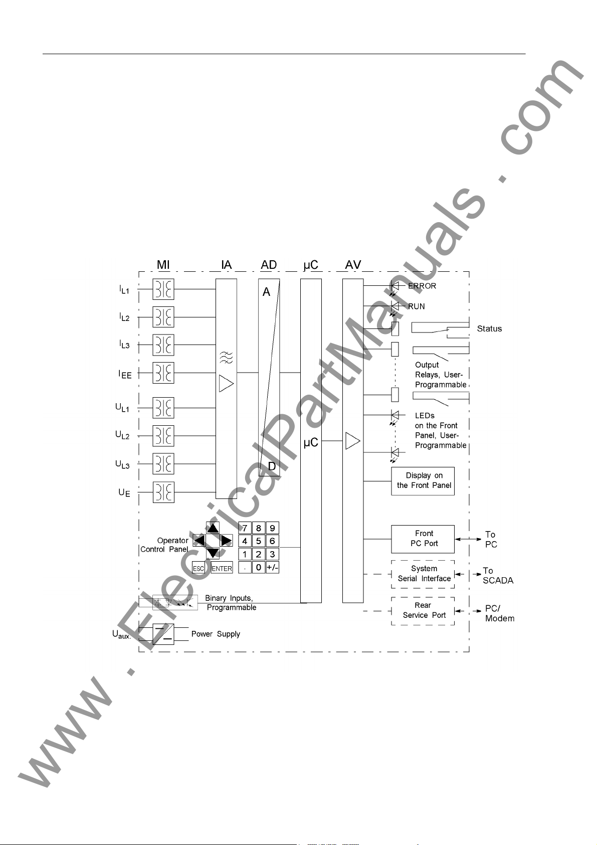
The digital Multi-Function Protection SIPROTEC® 7UM61 is equipped with a high performance microprocessor. All tasks such as the acquisition of the measured values
and issuing of commands to circuit breakers and other switching equipment, are processed digitally. Figure 1-1 shows the basic structure of the device.
Analog Inputs The measuring inputs (MI) are galvanically isolated, transform the currents and volt-
ages from the primary transformers and adapt them to the internal processing level of
the device. The device has 4 current and 4 voltage inputs. Three inputs are used on
each side of the protected object for measuring of the phase currents.
Figure 1-1 Hardware Structure of the Digital Machine Protection Device 7UM61 (maximum configuration)
1 current input is equipped with sensitive input transformers (IEE) and can measure
secondary currents in the mA range. 3 voltage inputs acquire the phase-to-earth voltages (connection to phase-to-phase voltages and voltage transformers in V connec-
18
7UM61 Manual
C53000-G1176-C127-3

1.1 Overall Operation
www . ElectricalPartManuals . com
tion is possible as well). The 4th voltage input is for displacement voltage measurement for stator earth fault protection.
The IA input amplifier group allows high impedance connection for analog input values
and contains filters optimized for measured value processing bandwidth and speed.
The AD analog digital converter group contains high resolution Σ∆ digital converters
(22 bits) and memory components for data transfer to the microcomputer.
Microcomputer System
Adaptation of Sampling Frequency
The implemented software is processed in the microcomputer system (µC). Essential
functions are:
• Filtering and conditioning of the measured signals,
• Continuous monitoring of the measured quantities
• Monitoring of the pickup conditions for the individual protective functions
• Querying of limit values and time sequences,
• Control of signals for logical functions,
• Decision for trip commands
• Signalling of protection behaviour via LEDs, LCD, relays or serial interfaces
• Storage of indications, fault data and fault values for fault analysis,
• Management of the operating system and its associated functions such as data recording, real-time clock, communication, interfaces, etc.
The frequency of the measured quantities is continuously measured and used for adjusting of the actual sampling frequency. This ensures that the protection and measurement functions produce correct results over a wide frequency range. This ensures
measuring accuracy in the frequency range from 11 Hz to 69 Hz.
The sampling frequency adaptation can, however, operate only when at least one a.c.
measured quantity is present at one of the analog inputs, with an amplitude of at least
5 % of rated value (“operational condition 1”).
If no suitable measured values are present, or if the frequency is below 11 Hz or above
70 Hz, the device operates in mode “operational condition 0”.
Binary Inputs and Outputs
F r o n t E l em e n ts Optical indicators (LEDs) and a front display panel (LC display) provide information on
7UM61 Manual
C53000-G1176-C127-3
Binary inputs and outputs from and to the computer system are routed via the I/O
modules (inputs and outputs). The computer system obtains the information from the
system (e.g remote resetting) or the external equipment (e.g. blocking commands).
Outputs are mainly commands that are issued to the switching devices and messages
for remote signalling of events and states.
the function of the device and indicate events, states and measured values. Integrated control and numeric keys in conjunction with the LCD facilitate local interaction with
the device. By this means all information on the device such as design and setting parameters, operation and disturbance indications and measured values can be queried,
(see also SIPROTEC
changed.
®
System Description /1/), and setting parameters can be
19

1 Introduction
www . ElectricalPartManuals . com
S e r i a l I n t e r f a c e s A serial operator interface in the front cover is provided for local communication with
a PC, using the operating program DIGSI
functions of the device.
A serial service
possible using DIGSI
devices to the PC or for operation via a modem. The service interface can be also
used for connecting a RTD-Box (see chapter 2.32)
All data can be transferred to a central control or monitoring system via the serial
system
transmission modes to suit the particular application.
A further interface is provided for time synchronization
ternal synchronization sources.
Further communication protocols can be implemented via additional communication
protocols.
Power Supply The functional units described are supplied by a power supply PS with the necessary
power in the different voltage levels. Voltage dips may occur if the voltage supply
system (substation battery) becomes short-circuited. Usually, they are bridged by a
capacitor (see also Technical Data).
interface. This interface may be provided with various protocols and physical
interface can likewise make communication via PC with the device
®
4. This is especially well suited for dedicated connection of the
®
4. This permits convenient operation of all
of the internal clock through ex-
20
7UM61 Manual
C53000-G1176-C127-3
1.2 Application Scope
www . ElectricalPartManuals . com
The SIPROTEC® 7UM61 device is a digital multi-function machine protection unit from
the 7UM6 Numerical Protection series. It provides all functions necessary for protection of generators and motors. As the scope of functions of the 7UM61 can be customized, it is suited for small, medium-sized and large generators.
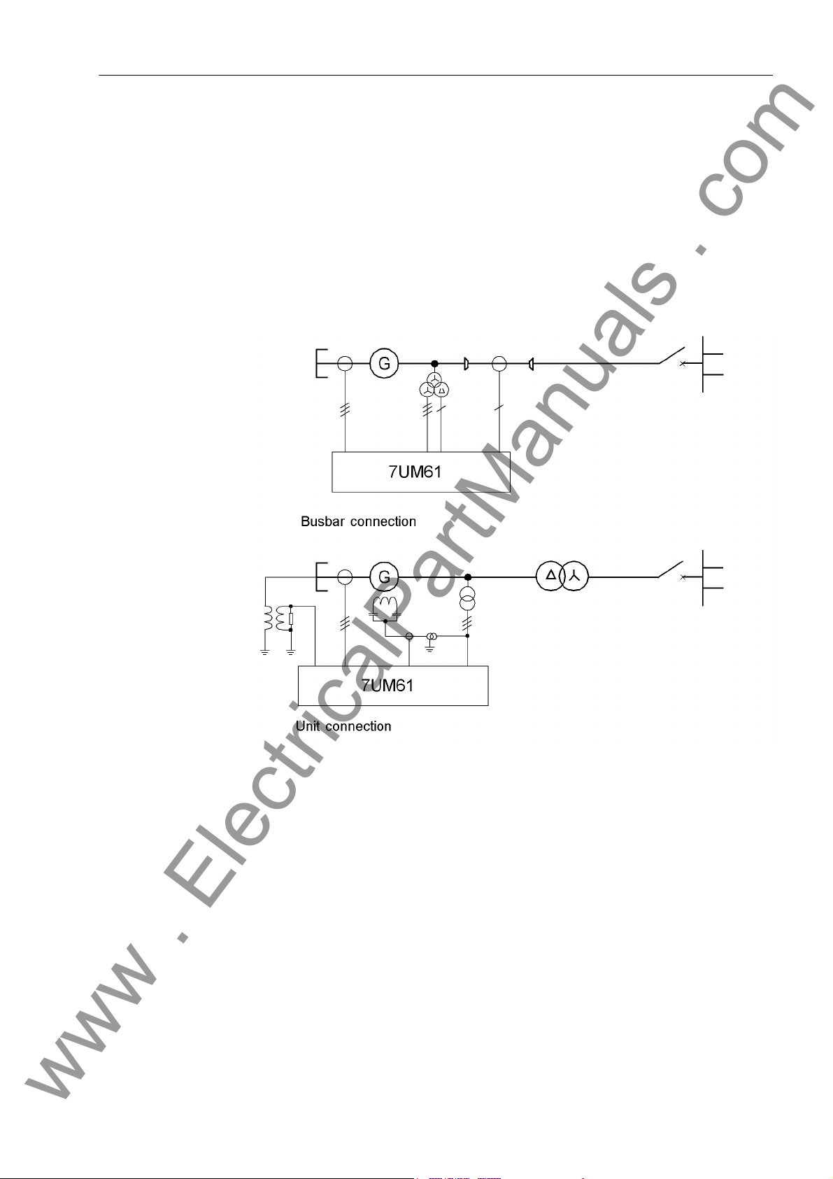
The device fulfills the protection requirements for the two typical basic connections:
• Busbar connection
• Unit connection
1.2 Application Scope
Figure 1-2 Typical Connections
The scalable software allows a wide range of applications. Corresponding function
packages can be selected for each particular application. For instance, alone with the
7UM61 device, it is possible to provide comprehensive and reliable protection of generators from small to medium capacity (approx. 0.5 - 5 MW).
Additionally, the device forms the basis for the protection of medium to large size generators (backup protection). In combination with the 7UM62 device (a further device
of the 7UM6 series), all protection requirements encountered in practice for the smallest to the largest machines can be met. This makes possible a consistent concept for
reserve protection capacity.
7UM61 Manual
C53000-G1176-C127-3
21

1 Introduction
www . ElectricalPartManuals . com
The 7UM61 device is usable for further applications such as
• Backup protection, since in addition to overcurrent protection, a large variety of protection functions allow, for example, monitoring of voltage and frequency load.
• Protection of synchronous and asynchronous motors.
• Mains Decoupling Device
Messages and Measured Values; Recording of Event
and Fault Data
Communication For communication with external operator, control and storage systems, serial inter-
Operator Interface on the Front Panel
The operating messages provide information about conditions in the power system
and the device itself. Measurement quantities and resulting computed values can be
displayed locally and communicated via the serial interfaces.
Annunciations of the devices can be presented by LEDs on the front panel (allocatable), processed further externally using output contacts (allocatable), combined with
user-definable logic functions and/or output via serial interfaces (see Communication
below).
During a generator or network fault (fault in the power system), important events and
state changes are stored in a fault annunciation buffer. The instantaneous or rms measured values during the fault are also stored in the device and are subsequently available for fault analysis.
faces are available.
A 9-pin DSUB socket on the front panel is used for local communication with a personal computer. By means of the SIPROTEC
and evaluation tasks can be executed via this user
modifying configuration parameters and settings, configuring user-specific logic functions, retrieving operational and fault messages and measured values, readout and
display of fault recordings, querying of devices statuses and measured values.
®
operating software DIGSI®, all operational
interface, such as specifying and
Rear Panel Interfaces
Depending on the individual ordering variant, additional interfaces are located on the
rear panel of the device. These interfaces allow an extensive communication with
other digital operating, control and memory components to be set up:
The service
nected to this interface. For this reason, remote operation is possible via PC and the
DIGSI
The system
control centre. The data cables or fibre optic cables can be used. Several standard
protocols are available for data transmission:
• IEC 60 870–5–103
Integration of the devices into the substation automation systems SINAUT
and SICAM
• Profibus DP
This protocol of automation technology allows transmission of indications and measured values.
• Modbus ASCII/RTU
This protocol of automation technology allows transmission of indications and measured values.
•DNP 3.0
This protocol of automation technology allows transmission of indications and measured values.
interface can be operated through data lines. Also, a modem can be con-
®
4 operating software, e.g. to operate several devices from a central PC.
interface is used for central communication between the device and a
®
®
can also be done with this profile.
LSA
22
7UM61 Manual
C53000-G1176-C127-3

1.3 Characteristics
www . ElectricalPartManuals . com
General Features • Powerful 32-bit microprocessor system.
• Complete digital processing of measured values and control, from sampling and
digitalization of measured quantities to tripping circuit breakers or other switchgear
devices.
• Total electrical separation between the internal processing stages of the device and
the external transformer, control and DC supply circuits of the system because of
the design of the binary inputs, outputs, and the DC converters.
1.3 Characteristics
Definite Time Overcurrent Protection
(I>) with Undervoltage Seal-In
• Simple device operation using the integrated operator and display panel or by
means of a connected PC running DIGSI
• Continuous computation and display of measured quantities.
• Storage of fault messages and instantaneous or rms values for fault recording.
• Continuous monitoring of measured values as well as of the hardware and software
of the device.
• Communication with central control and memory storage equipment via serial interfaces, optionally via data cable, modem, or optic fibre lines.
• Battery-buffered clock that can be synchronized with an IRIG-B (via satellite) or
DCF77 signal, binary input signal, or system interface command.
• Statistics: Recording of the number of trip signals instigated by the device and
logging of currents switched off last by the device, as well as accumulated shortcircuit currents of each pole of the circuit breaker.
• Operating Hours Counter: Tracking of operating hours of the equipment under load
being protected.
• Commissioning aids such as connection check, field rotation check, status display
of all binary inputs and outputs, and test measurement recording.
• 2 definite time stages I> and I>> for the 3 phase currents (I
• Undervoltage seal-in for synchronous machines whose excitation voltage is obtained from the machine terminals;
• Optionally additional directional determination with the high current stage I>>.
®
4.
, IL2, IL3).
L1
• Blocking capability e.g. for reverse-interlocking bus-bar protection with any stage.
Inverse Time Overcurrent Protection
(voltage-controlled)
Thermal Overload Protection
7UM61 Manual
C53000-G1176-C127-3
• Selection possible from various characteristics (IEC, ANSI).
• Optionally voltage-controlled or voltage-dependent alteration of current pick-up behaviour during undervoltage;
• Voltage influencing can be blocked by fuse failure monitor or via voltage transformer
protective circuit breaker.
• Temperature image of current heat losses (overload protection with full memory capability, single body thermal model).
• Additional adjustable warning levels based on temperature rise and current magnitude.
• Consideration of coolant and ambient temperatures possible.
23

1 Introduction
www . ElectricalPartManuals . com
Negative Sequence Protection
Underexcitation protection
Reverse Power Protection
Forward Power Supervision
• Precise evaluation of negative sequence component of the three phase currents.
• Alarm stage when a set unbalanced load is exceeded.
• Thermal characteristic with adjustable negative sequence factor and adjustable
cooldown time.
• High-speed trip stage for large unbalanced loads (can be used for short-circuit protection).
• Conductance measurement from positive sequence components.
• Multi-step characteristic for steady-state and dynamic stability limits;
• Consideration of excitation voltage (only via binary input).
• Calculation of power from positive sequence components.
• Highly sensitive and precise active power measurement (detection of small motor-
ing powers even with low power factor cos ϕ , angle error compensation).
• Insensitive to power fluctuations.
• Long-time stage and short-time stage (active with closed emergency tripping valve).
• Calculation of power from positive sequence components.
• Supervision of over-power (P>) and/or under-power (P<) of active power output
with individually adjustable power limits.
Impedance protection
Undervoltage Protection
Overvoltage Protection
Frequency Protection
Overexcitation Protection
• Optionally high-speed or high-accuracy measurement.
• Overcurrent pickup with undervoltage seal-in (for synchronous machines which
take their excitation voltage from the terminals).
• 2 impedance zones, 1 overreach zone (switchable via binary input), 4 time stages.
• Polygonal tripping characteristics;
• Two-stage undervoltage measurement of positive sequence component of voltages.
• Two-stage overvoltage measurement of the highest of the three voltages.
• Optionally with phase-to-phase voltages or phase-to-earth voltages.
• Monitoring on undershooting (f<) and/or overshooting (f>) with 4 frequency limits
and delay times that are independently adjustable.
• Insensitive to harmonics and abrupt phase angle changes.
• Settable undervoltage threshold.
• Calculation of the ratio U/f.
• Adjustable warning and tripping stage.
• Standard characteristic or arbitrary trip characteristic for calculation of the thermal
stress, selectable.
24
7UM61 Manual
C53000-G1176-C127-3

1.3 Characteristics
www . ElectricalPartManuals . com
Rate-of-FrequencyChange Protection
Vector Jump • Sensitive phase jump detection to be used for network disconnection.
90% Stator Earth Fault Protection
Sensitive Earth F a u l t P r o t e c t i o n
• Monitors whether the frequency overshoots (df/dt>) and/or undershoots (df/dt<) a
set limit value, with 4 individually settable limit values or delay times.
• Variable measuring windows
• Coupling to frequency protection pickup.
• Settable undervoltage threshold.
• Suitable for generators in unit connection and directly connected to busbars.
• Measurement of displacement voltage via the neutral or earthing transformer or by
calculation from phase-to-earth voltages.
• Highly sensitive earth current detection, optional with or without directional determination with zero sequence components (I
• Directional characteristic adjustable.
• Determination of the earth-faulted phase.
• Two-stage earth fault current measurement: I
• High sensitivity (adjustable on the secondary side from 2 mA).
• Can be used for stator earth fault or rotor earth fault detection.
, U0).
0
EE
>> and IEE>.
100% Stator Earth Fault Protection w i t h 3 r d H a r m o n i c
Motor Starting Time Supervision
Restart Inhibit for Motors
Breaker Failure Protection
• Measurement circuit monitoring for minimum current flow when used for rotor earth
fault protection.
• Detection of the 3rd harmonic of the voltage at the starpoint or broken delta winding
of an earthing transformer.
• In addition to the 90-%-stator earth fault protection there is a protection of the entire
stator winding (protective range 100 %).
• Inverse time overcurrent tripping based on an evaluation of the motor starting
current
• Inverse time delay with blocked rotor.
• Approximate computation of rotor overtemperature.
• Motor switchon is enabled only a if a restartup limit is undershot.
• Calculation of waiting time until automatic reclosure is enabled.
• Different prolongation of cooldown time constants for standstill/operation period is
taken into consideration.
• Possibility for disabling the start inhibit if emergency startup is required.
• By checking the current or evaluation of the breaker auxiliary contacts.
• Initiation of each integrated protection function allocated to the circuit breaker.
• Initiation possible through a binary input from an external protective device.
7UM61 Manual
C53000-G1176-C127-3
25

1 Introduction
www . ElectricalPartManuals . com
Inadvertent Energizing Protection
Threshold Supervisions
Temperature Detection by Thermoboxes
Phase Sequence Inversion
User-Defined Functions
• Damage limitation on inadvertent switching on of a stationary generator by fast
opening of the generator switch.
• Instantaneous value acquisition of the phase currents.
• Operational state and voltage supervision as well as fuse failure monitor are the
enable criteria.
• 6 freely assignable indications for threshold supervision.
• Implementation of fast supervision tasks with CFC.
• Acquisition of any ambient temperatures or coolant temperatures using thermoboxes and external temperature sensors.
• Selectable L1, L2, L3 or L1, L3, L2 via setting (static) or binary input (dynamic).
• Internal and external signals can be logically combined to establish user-defined
logic functions.
• All common logic functions (AND, OR, NOT, Exclusive OR, etc.).
• Time delays and limit value interrogations.
• Processing of measured values, including zero suppression, adding a knee characteristic for a transducer input, and live-zero monitoring.
Breaker Control • Circuit breakers can be opened and closed manually via programmable function
Measured Values Monitoring
keys, via the system interface (e.g. by SICAM
face (using a PC with DIGSI
• Feedback information on circuit breakers states via the breaker auxiliary contacts.
• Plausibility monitoring of the circuit breaker positions and interlocking conditions for
switching.
• Increased reliability thanks to monitoring of internal measuring circuits, of auxiliary
power supply, and of hardware and software.
• Current transformer and voltage transformer secondary circuits are monitored
using symmetry checks.
• Trip circuit monitoring possible via external circuitry.
• Phase sequence check.
■
®
).
®
or LSA), or via the operating inter-
26
7UM61 Manual
C53000-G1176-C127-3
Functions 2
www . ElectricalPartManuals . com
This chapter describes the numerous functions available on the SIPROTEC® 4
7UM61. It shows the setting possibilities for all the functions in maximum configuration. Instructions for deriving setting values and formulae, where required are provided.
Additionally it may be defined which functions are to be used.
2.1 Introduction, Reference Systems 29
2.2 Functional Scope 31
2.3 Power System Data 1 34
2.4 Change Group 39
2.5 Power System Data 2 40
2.6 Definite-Time Overcurrent Protection (I>, ANSI 50/51) with Undervoltage
Seal-In 42
2.7 Definite-Time Overcurrent Protection (I>>, ANSI 50, 51, 67) with Direction
Detection 46
2.8 Inverse-Time Overcurrent Protection (ANSI 51V) 52
2.9 Thermal Overload Protection (ANSI 49) 59
2.10 Unbalanced Load (Negative Sequence) Protection (ANSI 46) 70
2.11 Underexcitation (Loss-of-Field) Protection (ANSI 40) 77
2.12 Reverse Power Protection (ANSI 32R) 85
2.13 Forward Active Power Supervision (ANSI 32F) 89
2.14 Impedance Protection (ANSI 21) 92
2.15 Undervoltage Protection (ANSI 27) 103
2.16 Overvoltage Protection (ANSI 59) 106
2.17 Frequency Protection (ANSI 81) 109
2.18 Overexcitation (Volt/Hertz) Protection (ANSI 24) 113
2.19 Rate-of-Frequency-Change Protection df/dt (ANSI 81R) 118
2.20 Jump of Voltage Vector 123
2.21 90-%-Stator Earth Fault Protection (ANSI 59N, 64G, 67G) 128
2.22 Sensitive Earth Fault Protection (ANSI 51GN, 64R) 136
C53000-G1176-C127-3
277UM61 Manual

2 Functions
www . ElectricalPartManuals . com
2.23 100-%-Stator Earth Fault Protection with 3rd Harmonics
(ANSI 27/59TN 3rd Harm.) 140
2.24 Motor Starting Time Supervision (ANSI 48) 144
2.25 Restart Inhibit for Motors (ANSI 66, 49Rotor) 149
2.26 Breaker Failure Protection (ANSI 50BF) 157
2.27 Inadvertent Energization (ANSI 50, 27) 162
2.28 Measurement Supervision 166
2.29 Trip Circuit Supervision 176
2.30 Threshold supervision 183
2.31 External Trip Functions 189
2.32 RTD-Box 192
2.33 Phase Rotation Reversal 201
2.34 Protection Function Control 203
2.35 Ancillary Functions 208
2.36 Command Processing 221
28
7UM61 Manual
C53000-G1176-C127-3
2.1 Introduction, Reference Systems
www . ElectricalPartManuals . com
2.1 Introduction, Reference Systems
The following chapters explain the individual protective and additional functions and
provide information about the setting values.
2.1.1 Functional Description
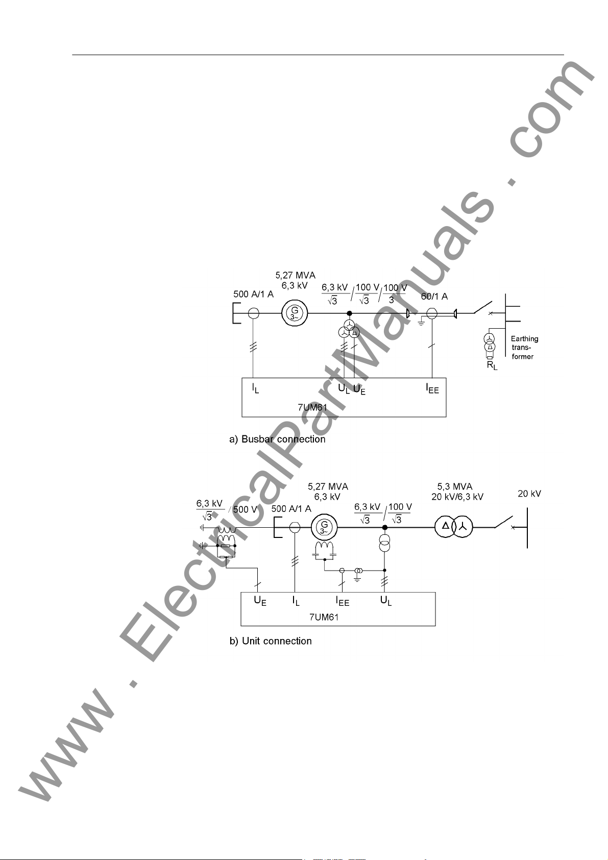
Generator The calculation examples are based on two smaller capacity reference power systems
with the two typical basic connections, i.e. the busbar connection and the unit connection (see following figure). All default settings of the relay are adapted accordingly.
Figure 2-1 Reference Systems
7UM61 Manual
C53000-G1176-C127-3
29

2 Functions
www . ElectricalPartManuals . com
Technical Data of the Reference Power Systems
Generator S
Current transformer: I
Toroidal c.t.: I
Voltage transformer: U
Transformer
Transformer: S
Zero point transformer:
= 5.27 MVA
N, T
= 6.3 kV
U
N, Gen
ING = 483 A
cos ϕ = 0.8
= 500 A; I
N,prim
= 60 A; I
N,prim
=(6.3/√3) kV U
N, prim
= 5.3 MVA
N, T
UOS = 20 kV
U = 6.3 kV
= 7 %
u
K
CT=
= 1 A
N, sec
= 1 A
N, sec
= (100/√3) V
N, sec
/3 = (100/3) V
U
en
Resistor divider: 5 : 1
Motor
Motor VN = 6600 V
I
= 126 A
N, M
I
I
T
Current transformer: I
= 624 A (Starting current)
StartCurr.
= 135 A (Permissible continuous stator cur-
max
= 8.5 s (Starting time at ISTRT)
STRT
= 200 A; I
N,prim
Further technical data are provided within the framework of the functional setting
specifications of the individual protective functions.
The calculated setting values are secondary setting values related to the device and
can be modified immediately by way of local operation.
For a complete reparametrization the operating program DIGSI
In this way, the user can specify primary values in addition to secondary settings. This
is done in the 7UM61 as a setting referred to the rated values of the object to be protected (e.g. I
N, G
dent, typical settings of the protective functions can be pre-specified. The data of the
individual power system are updated in the Power System Data 1 or Power
System Data 2 and conversion to secondary values is done by mouse clicking. All
necessary conversion formulas of the individual functions are stored in the operating
program.
; U
N, G
rent)
= 1 A
N, sec
®
4 is recommended.
; S
). This procedure has the advantage that system-indepen-
N, G
30
7UM61 Manual
C53000-G1176-C127-3
 Loading...