

Page 1

SIPROTEC
www . ElectricalPartManuals . com
Preface
Introduction 1
Functions 2
Mounting and Commissioning 3
Multi-Functional Generator
Protection Relay
7UM61
V4.1
Manual
Technical Data 4
Appendix A
Literature
Glossary
Index
C53000-G1176-C127-3
Page 2

Disclaimer of liability
www . ElectricalPartManuals . com
We have checked the text of this manual against the hardware
and software described. However, deviations from the description cannot be completely ruled out, so that no liability can be accepted for any errors or omissions contained in the information
given.
The information in this manual is checked periodically, and necessary corrections will be included in future editions. We appreciate any suggested improvements.
We reserve the right to make technical improvements without
notice.
Copyright
Copyright © Siemens AG 2003. All rights reserved.
Dissemination or reproduction of this document, or evaluation
and communication of its contents, is not authorized except
where expressly permitted. Violations are liable for damages. All
rights reserved, particularly for the purposes of patent application
or trademark registration.
Registered Trademarks
SIPROTEC, SINAUT, SICAM and DIGSI are registered trademarks of SIEMENS AG. Other designations in this manual may
be trademarks that if used by third parties for their own purposes
may violate the rights of the owner.
4.10.05
7UM61 Manual
C53000-G1176-C127-3
Page 3
Preface
www . ElectricalPartManuals . com
Purpose of this Manual
Target Audience Protection engineers, commissioning engineers, personnel concerned with adjust-
Applicability of this Manual
Indication of Conformity
This manual describes the functions, operation, installation, and commissioning of the
device 7UM61. In particular it contains:
• Information regarding the configuration of the device extent and descriptions of
device functions and settings → Chapter 2;
• Instructions for mounting and commissioning → Chapter 3;
• Compilation of technical data→ Chapter 4;
• As well as a compilation of the most significant data for experienced users in Appendix A.
®
General information about design, configuration, and operation of SIPROTEC
devices is laid down in the SIPROTEC
ment, checking, and service of selective protective equipment, automatic and control
facilities, and personnel of electrical facilities and power plants.
This manual is valid for: Multi-Functional Generator Protection Relay with Local
Control SIPROTEC
This product complies with the directive of the Council of the European Communities on the approximation of the laws of the Member States relating to electromagnetic compatibility (EMC Council Directive 89/336/EEC) and concerning electrical equipment for use within specified voltage limits (Low-voltage directive 73/23
EEC).
This conformity has been proved by tests conducted by Siemens AG in accordance with Article 10 of the Council Directive in agreement with the generic standards EN 50081 and EN 61000-6-2 (for EMC directive) and the standard
EN 60255-6 (for low-voltage directive). This device was designed and produced
for industrial use according to the EMC standard.
The product conforms with the international standard of the series IEC 60255 and
the German standard VDE 0435.
®
4 7UM61; firmware version V4.1.
®
System Description /1/.
4
This product is UL-certified according to the Technical Data:
C53000-G1176-C127-3
37UM61 Manual
Page 4
Preface
www . ElectricalPartManuals . com
Additional Support Should further information on the System SIPROTEC® 4 be desired or should partic-
ular problems arise which are not covered sufficiently for the purchaser's purpose, the
matter should be referred to the local Siemens representative.
Training Courses Individual course offerings may be found in our Training Catalogue, or questions may
be directed to our training centre in Nuremberg.
Instructions and
Warnings
The warnings and notes contained in this manual serve for your own safety and for
an appropriate lifetime of the device. Please observe them!
The following indicators and standard definitions are used:
DANGER
indicates that death, severe personal injury or substantial property damage will
result if proper precautions are not taken.
Warning
indicates that death, severe personal injury or substantial property damage can
result if proper precautions are not taken.
Caution
indicates that minor personal injury or property damage can result if proper precautions are not taken. This particularly applies to damage on or in the device itself and
consequential damage thereof.
Note
indicates information about the device or respective part of the instruction manual
which is essential to highlight.
WARNING!
When operating an electrical device, certain parts of the device inevitably have dangerous voltages.
Failure to observe these precautions can result in fatality, personal injury, or extensive
material damage.
Only qualified personnel shall work on and around this equipment. It must be thoroughly familiar with all warnings and safety notices of this manual as well as with the
applicable safety regulations.
The successful and safe operation of this device is dependent on proper handling, installation, operation, and maintenance by qualified personnel under observance of all
warnings and hints contained in this manual. In particular the general erection and
safety regulations (e.g. IEC, DIN, VDE, EN or other national and international standards) regarding the correct use of hoisting gear must be observed.
4
7UM61 Manual
C53000-G1176-C127-3
Page 5
Definition QUALIFIED PERSONNEL
www . ElectricalPartManuals . com
For the purpose of this instruction manual and product labels, a qualified person is
one who is familiar with the installation, construction and operation of the equipment
and the hazards involved. In addition, he has the following qualifications:
• Is trained and authorized to energize, de-energize, clear, ground and tag circuits
and equipment in accordance with established safety practices.
• Is trained in the proper care and use of protective equipment in accordance with
established safety practices.
• Is trained in rendering first aid.
Typographic and
Graphical Conventions
To designate terms which refer in the text to information of the device or for the
device, the following fonts are used:
Parameter names
Designators of configuration or function parameters which may appear word-forword in the display of the device or on the screen of a personal computer (with operation software DIGSI
also applies to header bars for selection menus.
1234A
Parameter addresses have the same character style as parameter names. Parameter addresses contain the suffix A in the overview tables if the parameter can only
be set in DIGSI
Parameter Conditions
Possible settings of text parameters, which may appear word-for-word in the
display of the device or on the screen of a personal computer (with operation software DIGSI
selection menus.
“Annunciations”
Designators for information, which may be output by the relay or required from other
devices or from the switch gear, are marked in a monospace type style in quotation
marks.
®
), are additionally written in italics. This also applies to header bars for
®
®
via the option Display additional settings.
Preface
), are marked in bold letters of a monospace type style. This
7UM61 Manual
C53000-G1176-C127-3
Deviations may be permitted in drawings and tables when the type of designator can
be obviously derived from the illustration.
The following symbols are used in drawings:
Device-internal logical input signal
Device-internal (logical) output signal
Internal input signal of an analog quantity
External binary input signal with number (binary input, input
indication)
External binary output signal with number (device indication)
5
Page 6
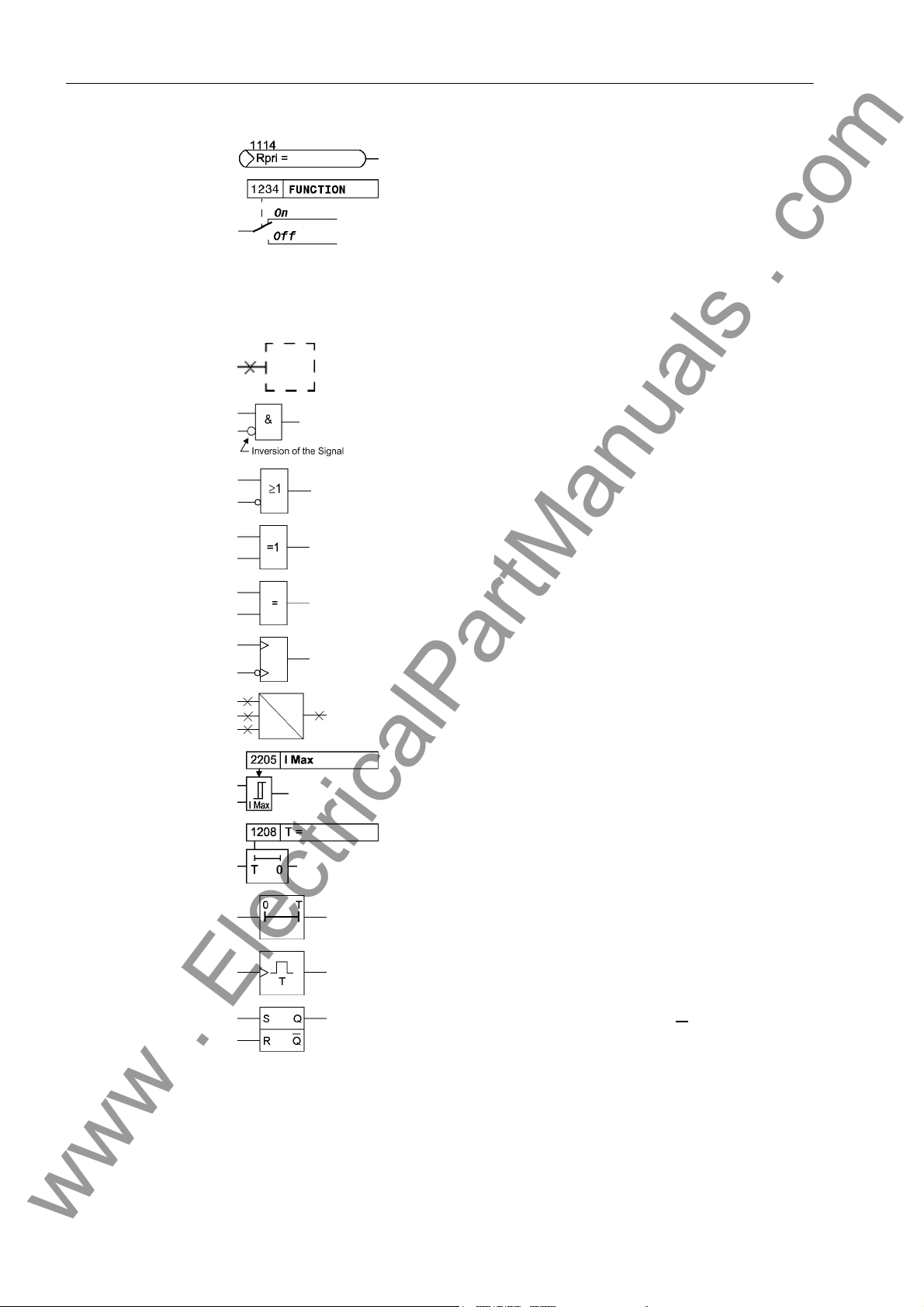
Preface
www . ElectricalPartManuals . com
External binary output signal with number (device indication)
used as input signal
Example of a parameter switch designated FUNCTION with
the address 1234 and the possible settings ON and OFF
Besides these, graphical symbols are used according to IEC 60617-12 and IEC
60617-13 or symbols derived from these standards. Some of the most frequently used
are listed below:
Input signal of an analog quantity
AND gate
OR gate
Exclusive–OR gate (antivalence): output is active, if only
one of the inputs is active
Equivalence: output is active, if both inputs are active or inactive at the same time
Dynamic inputs (edge–triggered) above with positive, below
with negative edge
Formation of one analog output signal from a number of
analog input signals
Limit stage with setting address and parameter designator
(name)
Timer (pickup delay T, example adjustable) with setting
address and parameter designator (name)
Timer (dropout delay T, example non-adjustable)
Dynamic triggered pulse timer T (monoflop)
Static memory (RS-flipflop) with setting input (S), resetting
input (R), output (Q) and inverted output (Q
■
6
)
7UM61 Manual
C53000-G1176-C127-3
Page 7

Contents
www . ElectricalPartManuals . com
1 Introduction. . . . . . . . . . . . . . . . . . . . . . . . . . . . . . . . . . . . . . . . . . . . . . . . . . . . . . . . . . . . . . . . . . . . 17
1.1 Overall Operation . . . . . . . . . . . . . . . . . . . . . . . . . . . . . . . . . . . . . . . . . . . . . . . . . . . . . . . . 18
1.2 Application Scope . . . . . . . . . . . . . . . . . . . . . . . . . . . . . . . . . . . . . . . . . . . . . . . . . . . . . . . . 21
1.3 Characteristics. . . . . . . . . . . . . . . . . . . . . . . . . . . . . . . . . . . . . . . . . . . . . . . . . . . . . . . . . . . 23
2 Functions. . . . . . . . . . . . . . . . . . . . . . . . . . . . . . . . . . . . . . . . . . . . . . . . . . . . . . . . . . . . . . . . . . . . . . 27
2.1 Introduction, Reference Systems . . . . . . . . . . . . . . . . . . . . . . . . . . . . . . . . . . . . . . . . . . . . 29
2.1.1 Functional Description . . . . . . . . . . . . . . . . . . . . . . . . . . . . . . . . . . . . . . . . . . . . . . . . . . . . . 29
2.2 Functional Scope. . . . . . . . . . . . . . . . . . . . . . . . . . . . . . . . . . . . . . . . . . . . . . . . . . . . . . . . . 31
2.2.1 Functional Description . . . . . . . . . . . . . . . . . . . . . . . . . . . . . . . . . . . . . . . . . . . . . . . . . . . . . 31
2.2.2 Setting Notes . . . . . . . . . . . . . . . . . . . . . . . . . . . . . . . . . . . . . . . . . . . . . . . . . . . . . . . . . . . . 31
2.2.3 Settings . . . . . . . . . . . . . . . . . . . . . . . . . . . . . . . . . . . . . . . . . . . . . . . . . . . . . . . . . . . . . . . . 32
2.3 Power System Data 1 . . . . . . . . . . . . . . . . . . . . . . . . . . . . . . . . . . . . . . . . . . . . . . . . . . . . . 34
2.3.1 Setting Notes . . . . . . . . . . . . . . . . . . . . . . . . . . . . . . . . . . . . . . . . . . . . . . . . . . . . . . . . . . . . 34
2.3.2 Settings . . . . . . . . . . . . . . . . . . . . . . . . . . . . . . . . . . . . . . . . . . . . . . . . . . . . . . . . . . . . . . . . 37
2.3.3 Information List . . . . . . . . . . . . . . . . . . . . . . . . . . . . . . . . . . . . . . . . . . . . . . . . . . . . . . . . . . 38
2.4 Change Group . . . . . . . . . . . . . . . . . . . . . . . . . . . . . . . . . . . . . . . . . . . . . . . . . . . . . . . . . . . 39
2.4.1 Setting Notes . . . . . . . . . . . . . . . . . . . . . . . . . . . . . . . . . . . . . . . . . . . . . . . . . . . . . . . . . . . . 39
2.4.2 Settings . . . . . . . . . . . . . . . . . . . . . . . . . . . . . . . . . . . . . . . . . . . . . . . . . . . . . . . . . . . . . . . . 39
2.4.3 Information List . . . . . . . . . . . . . . . . . . . . . . . . . . . . . . . . . . . . . . . . . . . . . . . . . . . . . . . . . . 39
2.5 Power System Data 2 . . . . . . . . . . . . . . . . . . . . . . . . . . . . . . . . . . . . . . . . . . . . . . . . . . . . . 40
2.5.1 Functional Description . . . . . . . . . . . . . . . . . . . . . . . . . . . . . . . . . . . . . . . . . . . . . . . . . . . . . 40
2.5.2 Setting Notes . . . . . . . . . . . . . . . . . . . . . . . . . . . . . . . . . . . . . . . . . . . . . . . . . . . . . . . . . . . . 40
2.5.3 Settings . . . . . . . . . . . . . . . . . . . . . . . . . . . . . . . . . . . . . . . . . . . . . . . . . . . . . . . . . . . . . . . . 40
2.5.4 Information List . . . . . . . . . . . . . . . . . . . . . . . . . . . . . . . . . . . . . . . . . . . . . . . . . . . . . . . . . . 40
2.6 Definite-Time Overcurrent Protection (I>, ANSI 50/51) with Undervoltage Seal-In . . . . . . . 42
2.6.1 Functional Description . . . . . . . . . . . . . . . . . . . . . . . . . . . . . . . . . . . . . . . . . . . . . . . . . . . . . 42
2.6.2 Setting Notes . . . . . . . . . . . . . . . . . . . . . . . . . . . . . . . . . . . . . . . . . . . . . . . . . . . . . . . . . . . . 43
2.6.3 Settings . . . . . . . . . . . . . . . . . . . . . . . . . . . . . . . . . . . . . . . . . . . . . . . . . . . . . . . . . . . . . . . . 44
2.6.4 Information List . . . . . . . . . . . . . . . . . . . . . . . . . . . . . . . . . . . . . . . . . . . . . . . . . . . . . . . . . . 45
C53000-G1176-C127-3
77UM61 Manual
Page 8

Contents
www . ElectricalPartManuals . com
2.7 Definite-Time Overcurrent Protection (I>>, ANSI 50, 51, 67) with Direction Detection . . . . 46
2.7.1 Function Description . . . . . . . . . . . . . . . . . . . . . . . . . . . . . . . . . . . . . . . . . . . . . . . . . . . . . . 46
2.7.2 Setting Notes . . . . . . . . . . . . . . . . . . . . . . . . . . . . . . . . . . . . . . . . . . . . . . . . . . . . . . . . . . . . 48
2.7.3 Settings . . . . . . . . . . . . . . . . . . . . . . . . . . . . . . . . . . . . . . . . . . . . . . . . . . . . . . . . . . . . . . . . 51
2.7.4 Information List . . . . . . . . . . . . . . . . . . . . . . . . . . . . . . . . . . . . . . . . . . . . . . . . . . . . . . . . . . 51
2.8 Inverse-Time Overcurrent Protection (ANSI 51V) . . . . . . . . . . . . . . . . . . . . . . . . . . . . . . . . 52
2.8.1 Functional Description . . . . . . . . . . . . . . . . . . . . . . . . . . . . . . . . . . . . . . . . . . . . . . . . . . . . . 52
2.8.2 Setting Notes . . . . . . . . . . . . . . . . . . . . . . . . . . . . . . . . . . . . . . . . . . . . . . . . . . . . . . . . . . . . 56
2.8.3 Settings . . . . . . . . . . . . . . . . . . . . . . . . . . . . . . . . . . . . . . . . . . . . . . . . . . . . . . . . . . . . . . . . 57
2.8.4 Information List . . . . . . . . . . . . . . . . . . . . . . . . . . . . . . . . . . . . . . . . . . . . . . . . . . . . . . . . . . 58
2.9 Thermal Overload Protection (ANSI 49) . . . . . . . . . . . . . . . . . . . . . . . . . . . . . . . . . . . . . . . 59
2.9.1 Functional Description . . . . . . . . . . . . . . . . . . . . . . . . . . . . . . . . . . . . . . . . . . . . . . . . . . . . . 59
2.9.2 Setting Notes . . . . . . . . . . . . . . . . . . . . . . . . . . . . . . . . . . . . . . . . . . . . . . . . . . . . . . . . . . . . 62
2.9.3 Settings . . . . . . . . . . . . . . . . . . . . . . . . . . . . . . . . . . . . . . . . . . . . . . . . . . . . . . . . . . . . . . . . 68
2.9.4 Information List . . . . . . . . . . . . . . . . . . . . . . . . . . . . . . . . . . . . . . . . . . . . . . . . . . . . . . . . . . 69
2.10 Unbalanced Load (Negative Sequence) Protection (ANSI 46) . . . . . . . . . . . . . . . . . . . . . . 70
2.10.1 Functional Description . . . . . . . . . . . . . . . . . . . . . . . . . . . . . . . . . . . . . . . . . . . . . . . . . . . . . 70
2.10.2 Setting Notes . . . . . . . . . . . . . . . . . . . . . . . . . . . . . . . . . . . . . . . . . . . . . . . . . . . . . . . . . . . . 72
2.10.3 Settings . . . . . . . . . . . . . . . . . . . . . . . . . . . . . . . . . . . . . . . . . . . . . . . . . . . . . . . . . . . . . . . . 75
2.10.4 Information List . . . . . . . . . . . . . . . . . . . . . . . . . . . . . . . . . . . . . . . . . . . . . . . . . . . . . . . . . . 76
2.11 Underexcitation (Loss-of-Field) Protection (ANSI 40) . . . . . . . . . . . . . . . . . . . . . . . . . . . . . 77
2.11.1 Function Description . . . . . . . . . . . . . . . . . . . . . . . . . . . . . . . . . . . . . . . . . . . . . . . . . . . . . . 77
2.11.2 Setting Notes . . . . . . . . . . . . . . . . . . . . . . . . . . . . . . . . . . . . . . . . . . . . . . . . . . . . . . . . . . . . 79
2.11.3 Settings . . . . . . . . . . . . . . . . . . . . . . . . . . . . . . . . . . . . . . . . . . . . . . . . . . . . . . . . . . . . . . . . 83
2.11.4 Information List . . . . . . . . . . . . . . . . . . . . . . . . . . . . . . . . . . . . . . . . . . . . . . . . . . . . . . . . . . 84
2.12 Reverse Power Protection (ANSI 32R) . . . . . . . . . . . . . . . . . . . . . . . . . . . . . . . . . . . . . . . . 85
2.12.1 Function Description . . . . . . . . . . . . . . . . . . . . . . . . . . . . . . . . . . . . . . . . . . . . . . . . . . . . . . 85
2.12.2 Setting Notes . . . . . . . . . . . . . . . . . . . . . . . . . . . . . . . . . . . . . . . . . . . . . . . . . . . . . . . . . . . . 86
2.12.3 Settings . . . . . . . . . . . . . . . . . . . . . . . . . . . . . . . . . . . . . . . . . . . . . . . . . . . . . . . . . . . . . . . . 88
2.12.4 Information List . . . . . . . . . . . . . . . . . . . . . . . . . . . . . . . . . . . . . . . . . . . . . . . . . . . . . . . . . . 88
2.13 Forward Active Power Supervision (ANSI 32F). . . . . . . . . . . . . . . . . . . . . . . . . . . . . . . . . . 89
2.13.1 Function Description . . . . . . . . . . . . . . . . . . . . . . . . . . . . . . . . . . . . . . . . . . . . . . . . . . . . . . 89
2.13.2 Setting Notes . . . . . . . . . . . . . . . . . . . . . . . . . . . . . . . . . . . . . . . . . . . . . . . . . . . . . . . . . . . . 90
2.13.3 Settings . . . . . . . . . . . . . . . . . . . . . . . . . . . . . . . . . . . . . . . . . . . . . . . . . . . . . . . . . . . . . . . . 91
2.13.4 Information List . . . . . . . . . . . . . . . . . . . . . . . . . . . . . . . . . . . . . . . . . . . . . . . . . . . . . . . . . . 91
2.14 Impedance Protection (ANSI 21) . . . . . . . . . . . . . . . . . . . . . . . . . . . . . . . . . . . . . . . . . . . . . 92
2.14.1 Functional Description . . . . . . . . . . . . . . . . . . . . . . . . . . . . . . . . . . . . . . . . . . . . . . . . . . . . . 92
2.14.2 Setting Notes . . . . . . . . . . . . . . . . . . . . . . . . . . . . . . . . . . . . . . . . . . . . . . . . . . . . . . . . . . . . 96
2.14.3 Settings . . . . . . . . . . . . . . . . . . . . . . . . . . . . . . . . . . . . . . . . . . . . . . . . . . . . . . . . . . . . . . . 101
2.14.4 Information List . . . . . . . . . . . . . . . . . . . . . . . . . . . . . . . . . . . . . . . . . . . . . . . . . . . . . . . . . 101
8
7UM61 Manual
C53000-G1176-C127-3
Page 9

Contents
www . ElectricalPartManuals . com
2.15 Undervoltage Protection (ANSI 27) . . . . . . . . . . . . . . . . . . . . . . . . . . . . . . . . . . . . . . . . . . 103
2.15.1 Functional Description . . . . . . . . . . . . . . . . . . . . . . . . . . . . . . . . . . . . . . . . . . . . . . . . . . . . 103
2.15.2 Setting Notes . . . . . . . . . . . . . . . . . . . . . . . . . . . . . . . . . . . . . . . . . . . . . . . . . . . . . . . . . . . 104
2.15.3 Settings . . . . . . . . . . . . . . . . . . . . . . . . . . . . . . . . . . . . . . . . . . . . . . . . . . . . . . . . . . . . . . . 105
2.15.4 Information List . . . . . . . . . . . . . . . . . . . . . . . . . . . . . . . . . . . . . . . . . . . . . . . . . . . . . . . . . 105
2.16 Overvoltage Protection (ANSI 59) . . . . . . . . . . . . . . . . . . . . . . . . . . . . . . . . . . . . . . . . . . . 106
2.16.1 Functional Description . . . . . . . . . . . . . . . . . . . . . . . . . . . . . . . . . . . . . . . . . . . . . . . . . . . . 106
2.16.2 Setting Notes . . . . . . . . . . . . . . . . . . . . . . . . . . . . . . . . . . . . . . . . . . . . . . . . . . . . . . . . . . . 106
2.16.3 Settings . . . . . . . . . . . . . . . . . . . . . . . . . . . . . . . . . . . . . . . . . . . . . . . . . . . . . . . . . . . . . . . 107
2.16.4 Information List . . . . . . . . . . . . . . . . . . . . . . . . . . . . . . . . . . . . . . . . . . . . . . . . . . . . . . . . . 108
2.17 Frequency Protection (ANSI 81) . . . . . . . . . . . . . . . . . . . . . . . . . . . . . . . . . . . . . . . . . . . . 109
2.17.1 Functional Description . . . . . . . . . . . . . . . . . . . . . . . . . . . . . . . . . . . . . . . . . . . . . . . . . . . . 109
2.17.2 Setting Notes . . . . . . . . . . . . . . . . . . . . . . . . . . . . . . . . . . . . . . . . . . . . . . . . . . . . . . . . . . . .110
2.17.3 Settings . . . . . . . . . . . . . . . . . . . . . . . . . . . . . . . . . . . . . . . . . . . . . . . . . . . . . . . . . . . . . . . . 111
2.17.4 Information List . . . . . . . . . . . . . . . . . . . . . . . . . . . . . . . . . . . . . . . . . . . . . . . . . . . . . . . . . .112
2.18 Overexcitation (Volt/Hertz) Protection (ANSI 24). . . . . . . . . . . . . . . . . . . . . . . . . . . . . . . . .113
2.18.1 Function Description . . . . . . . . . . . . . . . . . . . . . . . . . . . . . . . . . . . . . . . . . . . . . . . . . . . . . .113
2.18.2 Setting Notes . . . . . . . . . . . . . . . . . . . . . . . . . . . . . . . . . . . . . . . . . . . . . . . . . . . . . . . . . . . .115
2.18.3 Settings . . . . . . . . . . . . . . . . . . . . . . . . . . . . . . . . . . . . . . . . . . . . . . . . . . . . . . . . . . . . . . . .117
2.18.4 Information List . . . . . . . . . . . . . . . . . . . . . . . . . . . . . . . . . . . . . . . . . . . . . . . . . . . . . . . . . .117
2.19 Rate-of-Frequency-Change Protection df/dt (ANSI 81R) . . . . . . . . . . . . . . . . . . . . . . . . . . 118
2.19.1 Functional Description . . . . . . . . . . . . . . . . . . . . . . . . . . . . . . . . . . . . . . . . . . . . . . . . . . . . .118
2.19.2 Setting Notes . . . . . . . . . . . . . . . . . . . . . . . . . . . . . . . . . . . . . . . . . . . . . . . . . . . . . . . . . . . .119
2.19.3 Settings . . . . . . . . . . . . . . . . . . . . . . . . . . . . . . . . . . . . . . . . . . . . . . . . . . . . . . . . . . . . . . . 121
2.19.4 Information List . . . . . . . . . . . . . . . . . . . . . . . . . . . . . . . . . . . . . . . . . . . . . . . . . . . . . . . . . 122
2.20 Jump of Voltage Vector . . . . . . . . . . . . . . . . . . . . . . . . . . . . . . . . . . . . . . . . . . . . . . . . . . . 123
2.20.1 Function Description . . . . . . . . . . . . . . . . . . . . . . . . . . . . . . . . . . . . . . . . . . . . . . . . . . . . . 123
2.20.2 Setting Notes . . . . . . . . . . . . . . . . . . . . . . . . . . . . . . . . . . . . . . . . . . . . . . . . . . . . . . . . . . . 125
2.20.3 Settings . . . . . . . . . . . . . . . . . . . . . . . . . . . . . . . . . . . . . . . . . . . . . . . . . . . . . . . . . . . . . . . 126
2.20.4 Information List . . . . . . . . . . . . . . . . . . . . . . . . . . . . . . . . . . . . . . . . . . . . . . . . . . . . . . . . . 127
2.21 90-%-Stator Earth Fault Protection (ANSI 59N, 64G, 67G) . . . . . . . . . . . . . . . . . . . . . . . . 128
2.21.1 Functional Description . . . . . . . . . . . . . . . . . . . . . . . . . . . . . . . . . . . . . . . . . . . . . . . . . . . . 128
2.21.2 Setting Notes . . . . . . . . . . . . . . . . . . . . . . . . . . . . . . . . . . . . . . . . . . . . . . . . . . . . . . . . . . . 132
2.21.3 Settings . . . . . . . . . . . . . . . . . . . . . . . . . . . . . . . . . . . . . . . . . . . . . . . . . . . . . . . . . . . . . . . 134
2.21.4 Information List . . . . . . . . . . . . . . . . . . . . . . . . . . . . . . . . . . . . . . . . . . . . . . . . . . . . . . . . . 134
2.22 Sensitive Earth Fault Protection (ANSI 51GN, 64R) . . . . . . . . . . . . . . . . . . . . . . . . . . . . . 136
2.22.1 Functional Description . . . . . . . . . . . . . . . . . . . . . . . . . . . . . . . . . . . . . . . . . . . . . . . . . . . . 136
2.22.2 Setting Notes . . . . . . . . . . . . . . . . . . . . . . . . . . . . . . . . . . . . . . . . . . . . . . . . . . . . . . . . . . . 138
2.22.3 Settings . . . . . . . . . . . . . . . . . . . . . . . . . . . . . . . . . . . . . . . . . . . . . . . . . . . . . . . . . . . . . . . 139
2.22.4 Information List . . . . . . . . . . . . . . . . . . . . . . . . . . . . . . . . . . . . . . . . . . . . . . . . . . . . . . . . . 139
7UM61 Manual
C53000-G1176-C127-3
9
Page 10

Contents
www . ElectricalPartManuals . com
2.23 100-%-Stator Earth Fault Protection with 3rd Harmonics (ANSI 27/59TN 3rd Harm.). . . . 140
2.23.1 Functional Description . . . . . . . . . . . . . . . . . . . . . . . . . . . . . . . . . . . . . . . . . . . . . . . . . . . . 140
2.23.2 Setting Notes . . . . . . . . . . . . . . . . . . . . . . . . . . . . . . . . . . . . . . . . . . . . . . . . . . . . . . . . . . . 142
2.23.3 Settings . . . . . . . . . . . . . . . . . . . . . . . . . . . . . . . . . . . . . . . . . . . . . . . . . . . . . . . . . . . . . . . 143
2.23.4 Information List . . . . . . . . . . . . . . . . . . . . . . . . . . . . . . . . . . . . . . . . . . . . . . . . . . . . . . . . . 143
2.24 Motor Starting Time Supervision (ANSI 48) . . . . . . . . . . . . . . . . . . . . . . . . . . . . . . . . . . . . 144
2.24.1 Functional Description . . . . . . . . . . . . . . . . . . . . . . . . . . . . . . . . . . . . . . . . . . . . . . . . . . . . 144
2.24.2 Setting Notes . . . . . . . . . . . . . . . . . . . . . . . . . . . . . . . . . . . . . . . . . . . . . . . . . . . . . . . . . . . 146
2.24.3 Settings . . . . . . . . . . . . . . . . . . . . . . . . . . . . . . . . . . . . . . . . . . . . . . . . . . . . . . . . . . . . . . . 148
2.24.4 Information List . . . . . . . . . . . . . . . . . . . . . . . . . . . . . . . . . . . . . . . . . . . . . . . . . . . . . . . . . 148
2.25 Restart Inhibit for Motors (ANSI 66, 49Rotor) . . . . . . . . . . . . . . . . . . . . . . . . . . . . . . . . . . 149
2.25.1 Functional Description . . . . . . . . . . . . . . . . . . . . . . . . . . . . . . . . . . . . . . . . . . . . . . . . . . . . 149
2.25.2 Setting Notes . . . . . . . . . . . . . . . . . . . . . . . . . . . . . . . . . . . . . . . . . . . . . . . . . . . . . . . . . . . 152
2.25.3 Settings . . . . . . . . . . . . . . . . . . . . . . . . . . . . . . . . . . . . . . . . . . . . . . . . . . . . . . . . . . . . . . . 155
2.25.4 Information List . . . . . . . . . . . . . . . . . . . . . . . . . . . . . . . . . . . . . . . . . . . . . . . . . . . . . . . . . 156
2.26 Breaker Failure Protection (ANSI 50BF) . . . . . . . . . . . . . . . . . . . . . . . . . . . . . . . . . . . . . . 157
2.26.1 Functional Description . . . . . . . . . . . . . . . . . . . . . . . . . . . . . . . . . . . . . . . . . . . . . . . . . . . . 157
2.26.2 Setting Notes . . . . . . . . . . . . . . . . . . . . . . . . . . . . . . . . . . . . . . . . . . . . . . . . . . . . . . . . . . . 159
2.26.3 Settings . . . . . . . . . . . . . . . . . . . . . . . . . . . . . . . . . . . . . . . . . . . . . . . . . . . . . . . . . . . . . . . 160
2.26.4 Information List . . . . . . . . . . . . . . . . . . . . . . . . . . . . . . . . . . . . . . . . . . . . . . . . . . . . . . . . . 160
2.27 Inadvertent Energization (ANSI 50, 27) . . . . . . . . . . . . . . . . . . . . . . . . . . . . . . . . . . . . . . . 162
2.27.1 Functional Description . . . . . . . . . . . . . . . . . . . . . . . . . . . . . . . . . . . . . . . . . . . . . . . . . . . . 162
2.27.2 Setting Notes . . . . . . . . . . . . . . . . . . . . . . . . . . . . . . . . . . . . . . . . . . . . . . . . . . . . . . . . . . . 163
2.27.3 Settings . . . . . . . . . . . . . . . . . . . . . . . . . . . . . . . . . . . . . . . . . . . . . . . . . . . . . . . . . . . . . . . 164
2.27.4 Information List . . . . . . . . . . . . . . . . . . . . . . . . . . . . . . . . . . . . . . . . . . . . . . . . . . . . . . . . . 165
2.28 Measurement Supervision . . . . . . . . . . . . . . . . . . . . . . . . . . . . . . . . . . . . . . . . . . . . . . . . . 166
2.28.1 Functional Description . . . . . . . . . . . . . . . . . . . . . . . . . . . . . . . . . . . . . . . . . . . . . . . . . . . . 166
2.28.2 Setting Notes . . . . . . . . . . . . . . . . . . . . . . . . . . . . . . . . . . . . . . . . . . . . . . . . . . . . . . . . . . . 174
2.28.3 Settings . . . . . . . . . . . . . . . . . . . . . . . . . . . . . . . . . . . . . . . . . . . . . . . . . . . . . . . . . . . . . . . 175
2.28.4 Information List . . . . . . . . . . . . . . . . . . . . . . . . . . . . . . . . . . . . . . . . . . . . . . . . . . . . . . . . . 175
2.29 Trip Circuit Supervision . . . . . . . . . . . . . . . . . . . . . . . . . . . . . . . . . . . . . . . . . . . . . . . . . . . 176
2.29.1 Functional Description . . . . . . . . . . . . . . . . . . . . . . . . . . . . . . . . . . . . . . . . . . . . . . . . . . . . 176
2.29.2 Setting Notes . . . . . . . . . . . . . . . . . . . . . . . . . . . . . . . . . . . . . . . . . . . . . . . . . . . . . . . . . . . 180
2.29.3 Settings . . . . . . . . . . . . . . . . . . . . . . . . . . . . . . . . . . . . . . . . . . . . . . . . . . . . . . . . . . . . . . . 182
2.29.4 Information List . . . . . . . . . . . . . . . . . . . . . . . . . . . . . . . . . . . . . . . . . . . . . . . . . . . . . . . . . 182
2.30 Threshold supervision . . . . . . . . . . . . . . . . . . . . . . . . . . . . . . . . . . . . . . . . . . . . . . . . . . . . 183
2.30.1 Functional Description . . . . . . . . . . . . . . . . . . . . . . . . . . . . . . . . . . . . . . . . . . . . . . . . . . . . 183
2.30.2 Setting Notes . . . . . . . . . . . . . . . . . . . . . . . . . . . . . . . . . . . . . . . . . . . . . . . . . . . . . . . . . . . 185
2.30.3 Settings . . . . . . . . . . . . . . . . . . . . . . . . . . . . . . . . . . . . . . . . . . . . . . . . . . . . . . . . . . . . . . . 186
2.30.4 Information List . . . . . . . . . . . . . . . . . . . . . . . . . . . . . . . . . . . . . . . . . . . . . . . . . . . . . . . . . 188
10
7UM61 Manual
C53000-G1176-C127-3
Page 11

Contents
www . ElectricalPartManuals . com
2.31 External Trip Functions . . . . . . . . . . . . . . . . . . . . . . . . . . . . . . . . . . . . . . . . . . . . . . . . . . . 189
2.31.1 Functional Description . . . . . . . . . . . . . . . . . . . . . . . . . . . . . . . . . . . . . . . . . . . . . . . . . . . . 189
2.31.2 Setting Notes . . . . . . . . . . . . . . . . . . . . . . . . . . . . . . . . . . . . . . . . . . . . . . . . . . . . . . . . . . . 189
2.31.3 Settings . . . . . . . . . . . . . . . . . . . . . . . . . . . . . . . . . . . . . . . . . . . . . . . . . . . . . . . . . . . . . . . 190
2.31.4 Information List . . . . . . . . . . . . . . . . . . . . . . . . . . . . . . . . . . . . . . . . . . . . . . . . . . . . . . . . . 190
2.32 RTD-Box . . . . . . . . . . . . . . . . . . . . . . . . . . . . . . . . . . . . . . . . . . . . . . . . . . . . . . . . . . . . . . 192
2.32.1 Functional Description . . . . . . . . . . . . . . . . . . . . . . . . . . . . . . . . . . . . . . . . . . . . . . . . . . . . 192
2.32.2 Setting Notes . . . . . . . . . . . . . . . . . . . . . . . . . . . . . . . . . . . . . . . . . . . . . . . . . . . . . . . . . . . 193
2.32.3 Settings . . . . . . . . . . . . . . . . . . . . . . . . . . . . . . . . . . . . . . . . . . . . . . . . . . . . . . . . . . . . . . . 195
2.32.4 Information List . . . . . . . . . . . . . . . . . . . . . . . . . . . . . . . . . . . . . . . . . . . . . . . . . . . . . . . . . 199
2.33 Phase Rotation Reversal . . . . . . . . . . . . . . . . . . . . . . . . . . . . . . . . . . . . . . . . . . . . . . . . . . 201
2.33.1 Functional Description . . . . . . . . . . . . . . . . . . . . . . . . . . . . . . . . . . . . . . . . . . . . . . . . . . . . 201
2.33.2 Setting Notes . . . . . . . . . . . . . . . . . . . . . . . . . . . . . . . . . . . . . . . . . . . . . . . . . . . . . . . . . . . 202
2.34 Protection Function Control . . . . . . . . . . . . . . . . . . . . . . . . . . . . . . . . . . . . . . . . . . . . . . . . 203
2.34.1 Pickup Logic of Device . . . . . . . . . . . . . . . . . . . . . . . . . . . . . . . . . . . . . . . . . . . . . . . . . . . 203
2.34.1.1 Functional Description . . . . . . . . . . . . . . . . . . . . . . . . . . . . . . . . . . . . . . . . . . . . . . . . . . . . 203
2.34.2 Tripping Logic of Device . . . . . . . . . . . . . . . . . . . . . . . . . . . . . . . . . . . . . . . . . . . . . . . . . . 204
2.34.2.1 Functional Description . . . . . . . . . . . . . . . . . . . . . . . . . . . . . . . . . . . . . . . . . . . . . . . . . . . . 204
2.34.2.2 Setting Notes . . . . . . . . . . . . . . . . . . . . . . . . . . . . . . . . . . . . . . . . . . . . . . . . . . . . . . . . . . . 205
2.34.3 Fault Display on the LEDs/LCD. . . . . . . . . . . . . . . . . . . . . . . . . . . . . . . . . . . . . . . . . . . . . 205
2.34.3.1 Functional Description . . . . . . . . . . . . . . . . . . . . . . . . . . . . . . . . . . . . . . . . . . . . . . . . . . . . 205
2.34.3.2 Setting Notes . . . . . . . . . . . . . . . . . . . . . . . . . . . . . . . . . . . . . . . . . . . . . . . . . . . . . . . . . . . 205
2.34.4 Statistics . . . . . . . . . . . . . . . . . . . . . . . . . . . . . . . . . . . . . . . . . . . . . . . . . . . . . . . . . . . . . . 206
2.34.4.1 Functional Description . . . . . . . . . . . . . . . . . . . . . . . . . . . . . . . . . . . . . . . . . . . . . . . . . . . . 206
2.34.4.2 Information List . . . . . . . . . . . . . . . . . . . . . . . . . . . . . . . . . . . . . . . . . . . . . . . . . . . . . . . . . 207
2.35 Ancillary Functions . . . . . . . . . . . . . . . . . . . . . . . . . . . . . . . . . . . . . . . . . . . . . . . . . . . . . . 208
2.35.1 Processing of Annunciations . . . . . . . . . . . . . . . . . . . . . . . . . . . . . . . . . . . . . . . . . . . . . . . 208
2.35.1.1 Functional Description . . . . . . . . . . . . . . . . . . . . . . . . . . . . . . . . . . . . . . . . . . . . . . . . . . . . 208
2.35.2 Measurement . . . . . . . . . . . . . . . . . . . . . . . . . . . . . . . . . . . . . . . . . . . . . . . . . . . . . . . . . . .211
2.35.2.1 Functional Description . . . . . . . . . . . . . . . . . . . . . . . . . . . . . . . . . . . . . . . . . . . . . . . . . . . . .211
2.35.2.2 Information List . . . . . . . . . . . . . . . . . . . . . . . . . . . . . . . . . . . . . . . . . . . . . . . . . . . . . . . . . 215
2.35.3 Set Points (Measured Values) . . . . . . . . . . . . . . . . . . . . . . . . . . . . . . . . . . . . . . . . . . . . . . 215
2.35.3.1 Functional Description . . . . . . . . . . . . . . . . . . . . . . . . . . . . . . . . . . . . . . . . . . . . . . . . . . . . 215
2.35.3.2 Setting Notes . . . . . . . . . . . . . . . . . . . . . . . . . . . . . . . . . . . . . . . . . . . . . . . . . . . . . . . . . . . 216
2.35.3.3 Information List . . . . . . . . . . . . . . . . . . . . . . . . . . . . . . . . . . . . . . . . . . . . . . . . . . . . . . . . . 216
2.35.4 Oscillographic Fault Records. . . . . . . . . . . . . . . . . . . . . . . . . . . . . . . . . . . . . . . . . . . . . . . 216
2.35.4.1 Functional Description . . . . . . . . . . . . . . . . . . . . . . . . . . . . . . . . . . . . . . . . . . . . . . . . . . . . 216
2.35.4.2 Setting Notes . . . . . . . . . . . . . . . . . . . . . . . . . . . . . . . . . . . . . . . . . . . . . . . . . . . . . . . . . . . 217
2.35.4.3 Settings . . . . . . . . . . . . . . . . . . . . . . . . . . . . . . . . . . . . . . . . . . . . . . . . . . . . . . . . . . . . . . . 217
2.35.4.4 Information List . . . . . . . . . . . . . . . . . . . . . . . . . . . . . . . . . . . . . . . . . . . . . . . . . . . . . . . . . 218
2.35.5 Date and Time Stamping . . . . . . . . . . . . . . . . . . . . . . . . . . . . . . . . . . . . . . . . . . . . . . . . . . 218
2.35.5.1 Functional Description . . . . . . . . . . . . . . . . . . . . . . . . . . . . . . . . . . . . . . . . . . . . . . . . . . . . 218
2.35.6 Commissioning Aids . . . . . . . . . . . . . . . . . . . . . . . . . . . . . . . . . . . . . . . . . . . . . . . . . . . . . 219
2.35.6.1 Functional Description . . . . . . . . . . . . . . . . . . . . . . . . . . . . . . . . . . . . . . . . . . . . . . . . . . . . 219
7UM61 Manual
C53000-G1176-C127-3
11
Page 12

Contents
www . ElectricalPartManuals . com
2.36 Command Processing . . . . . . . . . . . . . . . . . . . . . . . . . . . . . . . . . . . . . . . . . . . . . . . . . . . . 221
2.36.1 Control Device . . . . . . . . . . . . . . . . . . . . . . . . . . . . . . . . . . . . . . . . . . . . . . . . . . . . . . . . . . 221
2.36.1.1 Functional Description . . . . . . . . . . . . . . . . . . . . . . . . . . . . . . . . . . . . . . . . . . . . . . . . . . . . 221
2.36.2 Types of Commands . . . . . . . . . . . . . . . . . . . . . . . . . . . . . . . . . . . . . . . . . . . . . . . . . . . . . 222
2.36.2.1 Functional Description . . . . . . . . . . . . . . . . . . . . . . . . . . . . . . . . . . . . . . . . . . . . . . . . . . . . 222
2.36.3 Command Sequence . . . . . . . . . . . . . . . . . . . . . . . . . . . . . . . . . . . . . . . . . . . . . . . . . . . . . 222
2.36.3.1 Functional Description . . . . . . . . . . . . . . . . . . . . . . . . . . . . . . . . . . . . . . . . . . . . . . . . . . . . 223
2.36.4 System Interlocking . . . . . . . . . . . . . . . . . . . . . . . . . . . . . . . . . . . . . . . . . . . . . . . . . . . . . . 224
2.36.4.1 Functional Description . . . . . . . . . . . . . . . . . . . . . . . . . . . . . . . . . . . . . . . . . . . . . . . . . . . . 224
2.36.5 Command Logging/Acknowledgement . . . . . . . . . . . . . . . . . . . . . . . . . . . . . . . . . . . . . . . 231
2.36.5.1 Description. . . . . . . . . . . . . . . . . . . . . . . . . . . . . . . . . . . . . . . . . . . . . . . . . . . . . . . . . . . . . 231
3 Mounting and Commissioning . . . . . . . . . . . . . . . . . . . . . . . . . . . . . . . . . . . . . . . . . . . . . . . . . . . 233
3.1 Mounting and Connections . . . . . . . . . . . . . . . . . . . . . . . . . . . . . . . . . . . . . . . . . . . . . . . . 234
3.1.1 Configuration Information . . . . . . . . . . . . . . . . . . . . . . . . . . . . . . . . . . . . . . . . . . . . . . . . . 234
3.1.2 Hardware Modifications . . . . . . . . . . . . . . . . . . . . . . . . . . . . . . . . . . . . . . . . . . . . . . . . . . . 236
3.1.2.1 General . . . . . . . . . . . . . . . . . . . . . . . . . . . . . . . . . . . . . . . . . . . . . . . . . . . . . . . . . . . . . . . 236
3.1.2.2 Disassembly . . . . . . . . . . . . . . . . . . . . . . . . . . . . . . . . . . . . . . . . . . . . . . . . . . . . . . . . . . . 238
3.1.2.3 Switch Elements on the PCBs . . . . . . . . . . . . . . . . . . . . . . . . . . . . . . . . . . . 241
3.1.2.4 Interface Modules . . . . . . . . . . . . . . . . . . . . . . . . . . . . . . . . . . . . . . . . . . . . . . . . . . . . . . . 249
3.1.2.5 Reassembly . . . . . . . . . . . . . . . . . . . . . . . . . . . . . . . . . . . . . . . . . . . . . . . . . . . . . . . . . . . . 251
3.1.3 Mounting . . . . . . . . . . . . . . . . . . . . . . . . . . . . . . . . . . . . . . . . . . . . . . . . . . . . . . . . . . . . . . 252
3.1.3.1 Panel Flush Mounting . . . . . . . . . . . . . . . . . . . . . . . . . . . . . . . . . . . . . . . . . . . . . . . . . . . . 252
3.1.3.2 Rack Mounting and Cubicle Mounting . . . . . . . . . . . . . . . . . . . . . . . . . . . . . . . . . . . . . . . . 253
3.1.3.3 Panel Surface Mounting . . . . . . . . . . . . . . . . . . . . . . . . . . . . . . . . . . . . . . . . . . . . . . . . . . 254
3.2 Checking Connections. . . . . . . . . . . . . . . . . . . . . . . . . . . . . . . . . . . . . . . . . . . . . . . . . . . . 255
3.2.1 Checking Data Connections of Serial Interfaces . . . . . . . . . . . . . . . . . . . . . . . . . . . . . . . . 255
3.2.2 Checking Device Connections . . . . . . . . . . . . . . . . . . . . . . . . . . . . . . . . . . . 257
3.2.3 Checking System Incorporation. . . . . . . . . . . . . . . . . . . . . . . . . . . . . . . . . . . . . . . . . . . . . 259
3.3 Commissioning . . . . . . . . . . . . . . . . . . . . . . . . . . . . . . . . . . . . . . . . . . . . . . . . . . . . . . . . . 262
3.3.1 Test Mode and Transmission Block . . . . . . . . . . . . . . . . . . . . 263
3.3.2 Testing System Ports . . . . . . . . . . . . . . . . . . . . . . . . . . . . . . . . . . . . . . . . . 263
3.3.3 Checking the Binary Inputs and Outputs . . . . . . . . . . . . . . . . . . . . . . . . . . . 265
3.3.4 Testing Circuit Breaker Failure Protection . . . . . . . . . . . . . . . . . . . . . 268
3.3.5 Testing User-defined Functions . . . . . . . . . . . . . . . . . . . . . . . . . . . . . . . . . . . . 268
3.3.6 Trip/Close Tests for the Configured Operating Devices . . . . . . . . . . . . . . . . 268
3.3.7 Commissioning Test with the Machine. . . . . . . . . . . . . . . . . . . . . . . . . . . . . . . . . . . . . . . . 269
3.3.8 Checking the Current Circuits . . . . . . . . . . . . . . . . . . . . . . . . . . . . . . . . . . . . . . . . . . . . . . 272
3.3.9 Checking the Voltage Circuits . . . . . . . . . . . . . . . . . . . . . . . . . . . . . . . . . . 274
3.3.10 Checking the Stator Earth Fault Protection . . . . . . . . . . . . . . . . . . . . . . . . . . . . . . . . . . 276
3.3.11 Checking the Sensitive Earth Fault Protection when Used for Rotor Earth Fault Protec-
tion . . . . . . . . . . . . . . . . . . . . . . . . . . . . . . . . . . . . . . . . . . . . . . . . . . . . . . . . 285
3.3.12 Tests with the Network . . . . . . . . . . . . . . . . . . . . . . . . . . . . . . . . . . . . . . . . . 285
3.3.13 Setup of a test fault recording . . . . . . . . . . . . . . . . . . . . . . . . . . . . . . . . . . . . . . . . . . . . . . 289
3.4 Final Preparation of the Device . . . . . . . . . . . . . . . . . . . . . . . . . . . . . . . . . . 291
12
7UM61 Manual
C53000-G1176-C127-3
Page 13

Contents
www . ElectricalPartManuals . com
4 Technical Data. . . . . . . . . . . . . . . . . . . . . . . . . . . . . . . . . . . . . . . . . . . . . . . . . . . . . . . . . . . . . . . . . 293
4.1 General . . . . . . . . . . . . . . . . . . . . . . . . . . . . . . . . . . . . . . . . . . . . . . . . . . . . . . . . . . . . . . . 295
4.1.1 Analog Inputs/Outputs . . . . . . . . . . . . . . . . . . . . . . . . . . . . . . . . . . . . . . . . . 295
4.1.2 Auxiliary Voltage . . . . . . . . . . . . . . . . . . . . . . . . . . . . . . . . . . . . . . . . . . . . . . . . . . . . 295
4.1.3 Binary Inputs and Outputs . . . . . . . . . . . . . . . . . . . . . . . . . . . . . . . . . . . . 296
4.1.4 Communication Interfaces . . . . . . . . . . . . . . . . . . . . . . . . . . . . . . . . . . . . . . . . . . . . . 297
4.1.5 Electrical Tests . . . . . . . . . . . . . . . . . . . . . . . . . . . . . . . . . . . . . . . . . . . . . . . . . . . . . . . . 301
4.1.6 Mechanical Tests . . . . . . . . . . . . . . . . . . . . . . . . . . . . . . . . . . . . . . . . . . . . . . . . . . . . . . 303
4.1.7 Climatic Stress Tests . . . . . . . . . . . . . . . . . . . . . . . . . . . . . . . . . . . . . . . . . . . . . . . . 304
4.1.8 Deployment Conditions . . . . . . . . . . . . . . . . . . . . . . . . . . . . . . . . . . . . . . 304
4.1.9 Certifications . . . . . . . . . . . . . . . . . . . . . . . . . . . . . . . . . . . . . . . . . . . . . . . . . . . . . . . . . 305
4.1.10 Construction . . . . . . . . . . . . . . . . . . . . . . . . . . . . . . . . . . . . . . . . . . . . . . . . . . . . . . . 305
4.2 Definite-Time Overcurrent Protection (I>, ANSI 50/51; I>>, ANSI 50/51/67) . . . . 306
4.3 Inverse-Time Overcurrent Protection (ANSI 51V) . . . . . . . . . . . . . . . . . . . . . . . . . . 308
4.4 Thermal Overload Protection (ANSI 49) . . . . . . . . . . . . . . . . . . . . . . . . . . . . . . . . . . 315
4.5 Unbalanced Load (Negative Sequence) Protection (ANSI 46) . . . . . . . . . . . . . . . . 317
4.6 Underexcitation (Loss-of-Field) Protection (ANSI 40) . . . . . . . . . . . . . . . . . . . . . 319
4.7 Reverse Power Protection (ANSI 32R) . . . . . . . . . . . . . . . . . . . . . . . . . . . . . . . . . . 320
4.8 Forward Active Power Supervision (ANSI 32F) . . . . . . . . . . . . . . . . . . . . . . . . . . . . . . . 321
4.9 Impedance Protection (ANSI 21) . . . . . . . . . . . . . . . . . . . . . . . . . . . . . . . . . . . . . . 322
4.10 Undervoltage Protection (ANSI 27) . . . . . . . . . . . . . . . . . . . . . . . . . . . . . . . . . . . . . . . . 323
4.11 Overvoltage Protection (ANSI 59) . . . . . . . . . . . . . . . . . . . . . . . . . . . . . . . . . . . . . . . . . 324
4.12 Frequency Protection (ANSI 81) . . . . . . . . . . . . . . . . . . . . . . . . . . . . . . . . . . . . . . . . . . 325
4.13 Overexcitation (Volt/Hertz) Protection (ANSI 24) . . . . . . . . . . . . . . . . . . . . . . . . . . . . . . 326
4.14 Rate-of-Frequency-Change Protection df/dt (ANSI 81R) . . . . . . . . . . . . . . . . . . . . . . . 328
4.15 Jump of Voltage Vector . . . . . . . . . . . . . . . . . . . . . . . . . . . . . . . . . . . . . . . . . . . . 329
4.16 90-%-Stator Earth Fault Protection (ANSI 59N, 64G, 67G) . . . . . . . . . . . . . . . . . . . . 330
4.17 Sensitive Earth Fault Protection (ANSI 51GN, 64R) . . . . . . . . . . . . . . . . . . . . . . . . . . . 331
4.18 100-%-Stator Earth Fault Protection with 3rd Harmonics (ANSI 27/59TN 3rd Harm.) . 332
4.19 Motor Starting Time Supervision (ANSI 48) . . . . . . . . . . . . . . . . . . . . . . . . . . . . . . . . . . 333
4.20 Restart Inhibit for Motors (ANSI 66, 49Rotor) . . . . . . . . . . . . . . . . . . . . . . . . . . . . 334
4.21 Breaker Failure Protection (ANSI 50BF) . . . . . . . . . . . . . . . . . . . . . . . . . . . . . . . . . . . . 335
4.22 Inadvertent Energization (ANSI 50, 27) . . . . . . . . . . . . . . . . . . . . . . . . . . . . . . . . . . . . . 336
4.23 RTD-Box . . . . . . . . . . . . . . . . . . . . . . . . . . . . . . . . . . . . . . . . . . . . . . . . . . . . . . 337
4.24 Auxiliary Functions . . . . . . . . . . . . . . . . . . . . . . . . . . . . . . . . . . . . . . . . . . . . . . . . . . . . 338
7UM61 Manual
C53000-G1176-C127-3
13
Page 14

Contents
www . ElectricalPartManuals . com
4.25 Operating Ranges of the Protection Functions . . . . . . . . . . . . . . . . . . . . . . . . . . . . . . . 343
4.26 Dimensions . . . . . . . . . . . . . . . . . . . . . . . . . . . . . . . . . . . . . . . . . . . . . . . . . . . . . . . . . . . . 345
4.26.1 Panel Flush and Cubicle Mounting – 7UM611 . . . . . . . . . . . . . . . . . . . . . . . . . . . . . . . . 345
4.26.2 Panel Flush and Cubicle Mounting – 7UM612 . . . . . . . . . . . . . . . . . . . . . . . . . . . . . . . 346
4.26.3 Panel Flush Mounting – 7UM611 . . . . . . . . . . . . . . . . . . . . . . . . . . . . . . . . . . . . . . . . . . 347
4.26.4 Panel Flush Mounting – 7UM611 . . . . . . . . . . . . . . . . . . . . . . . . . . . . . . . . . . . . . . . . . . 347
4.26.5 Dimensions of Coupling Unit 7XR6100-0CA0 for Panel Flush Mounting . . . . . . . 348
4.26.6 Dimensions of Coupling Unit 7XR6100-0BA0 for Panel Flush Mounting . . . . . . . . . . . . . 349
4.26.7 Dimension diagrams 3PP13 . . . . . . . . . . . . . . . . . . . . . . . . . . . . . . . . . . . . . 350
A Appendix . . . . . . . . . . . . . . . . . . . . . . . . . . . . . . . . . . . . . . . . . . . . . . . . . . . . . . . . . . . . . . . . . . . . . 351
A.1 Ordering Information and Accessories . . . . . . . . . . . . . . . . . . . . . . . . . . . . . . . . . . . . . . . 352
A.1.1 Ordering Information . . . . . . . . . . . . . . . . . . . . . . . . . . . . . . . . . . . . . . . . . . . . . . . . . . . . . 352
A.1.1.1 7UM61 . . . . . . . . . . . . . . . . . . . . . . . . . . . . . . . . . . . . . . . . . . . . . . . . . . . . . . . . . . . . . . . . 352
A.1.2 Accessories . . . . . . . . . . . . . . . . . . . . . . . . . . . . . . . . . . . . . . . . . . . . . . . . . . . . . . . . . . . . 354
A.2 Terminal Assignments . . . . . . . . . . . . . . . . . . . . . . . . . . . . . . . . . . . . . . . . . . . . . . . . . . . . 357
A.2.1 General Diagram . . . . . . . . . . . . . . . . . . . . . . . . . . . . . . . . . . . . . . . . . . . . . . . . . . . . . . . . 357
A.2.2 General Diagram (Surface Mounting Version). . . . . . . . . . . . . . . . . . . . . . . . . . . . . . . . . . 358
A.2.3 General Diagram . . . . . . . . . . . . . . . . . . . . . . . . . . . . . . . . . . . . . . . . . . . . . . . . . . . . . . . . 359
A.2.4 General Diagram (Surface Mounting Version). . . . . . . . . . . . . . . . . . . . . . . . . . . . . . . . . . 360
A.3 Connection Examples . . . . . . . . . . . . . . . . . . . . . . . . . . . . . . . . . . . . . . . . . . . . . . . . . . . . 361
A.3.1 Connection Examples . . . . . . . . . . . . . . . . . . . . . . . . . . . . . . . . . . . . . . . . . . . . . . . . . . . . 361
A.3.2 Connection Examples for Thermobox . . . . . . . . . . . . . . . . . . . . . . . . . . . . . . . . . . . . . . . . 370
A.3.3 Schematic Diagram of Accessories . . . . . . . . . . . . . . . . . . . . . . . . . . . . . . . . . . . . . . . . . . 371
A.4 Default Settings . . . . . . . . . . . . . . . . . . . . . . . . . . . . . . . . . . . . . . . . . . . . . . . . . . . . . . . . . 373
A.4.1 LEDs . . . . . . . . . . . . . . . . . . . . . . . . . . . . . . . . . . . . . . . . . . . . . . . . . . . . . . . . . . . . . . . . . 373
A.4.2 Binary Input . . . . . . . . . . . . . . . . . . . . . . . . . . . . . . . . . . . . . . . . . . . . . . . . . . . . . . . . . . . . 373
A.4.3 Binary Output. . . . . . . . . . . . . . . . . . . . . . . . . . . . . . . . . . . . . . . . . . . . . . . . . . . . . . . . . . . 374
A.4.4 Function Keys . . . . . . . . . . . . . . . . . . . . . . . . . . . . . . . . . . . . . . . . . . . . . . . . . . . . . . . . . . 375
A.4.5 Default Display. . . . . . . . . . . . . . . . . . . . . . . . . . . . . . . . . . . . . . . . . . . . . . . . . . . . . . . . . . 375
A.4.6 Pre-defined CFC Charts . . . . . . . . . . . . . . . . . . . . . . . . . . . . . . . . . . . . . . . . . . . . . . . . . . 376
A.5 Protocol-dependent Functions. . . . . . . . . . . . . . . . . . . . . . . . . . . . . . . . . . . . . . . . . . . . . . 377
A.6 Functional Scope . . . . . . . . . . . . . . . . . . . . . . . . . . . . . . . . . . . . . . . . . . . . . . . . . . . . . . . . 378
A.7 Settings . . . . . . . . . . . . . . . . . . . . . . . . . . . . . . . . . . . . . . . . . . . . . . . . . . . . . . . . . . . . . . . 380
A.8 Information List . . . . . . . . . . . . . . . . . . . . . . . . . . . . . . . . . . . . . . . . . . . . . . . . . . . . . . . . . 391
A.9 Group Alarms. . . . . . . . . . . . . . . . . . . . . . . . . . . . . . . . . . . . . . . . . . . . . . . . . . . . . . . . . . . 407
A.10 Measured Values. . . . . . . . . . . . . . . . . . . . . . . . . . . . . . . . . . . . . . . . . . . . . . . . . . . . . . . . 408
14
7UM61 Manual
C53000-G1176-C127-3
Page 15

Contents
www . ElectricalPartManuals . com
Literature . . . . . . . . . . . . . . . . . . . . . . . . . . . . . . . . . . . . . . . . . . . . . . . . . . . . . . . . . . . . . . . . . . . . . .411
Glossary . . . . . . . . . . . . . . . . . . . . . . . . . . . . . . . . . . . . . . . . . . . . . . . . . . . . . . . . . . . . . . . . . . . . . 413
Index . . . . . . . . . . . . . . . . . . . . . . . . . . . . . . . . . . . . . . . . . . . . . . . . . . . . . . . . . . . . . . . . . . . . . . . . 421
7UM61 Manual
C53000-G1176-C127-3
15
Page 16

Contents
www . ElectricalPartManuals . com
16
7UM61 Manual
C53000-G1176-C127-3
Page 17

Introduction 1
www . ElectricalPartManuals . com
The SIPROTEC® 7UM61 devices are introduced in this section. An overview of the
7UM61 is presented with its application areas, features, and scope of functions.
1.1 Overall Operation 18
1.2 Application Scope 21
1.3 Characteristics 23
C53000-G1176-C127-3
177UM61 Manual
Page 18
1 Introduction
www . ElectricalPartManuals . com
1.1 Overall Operation
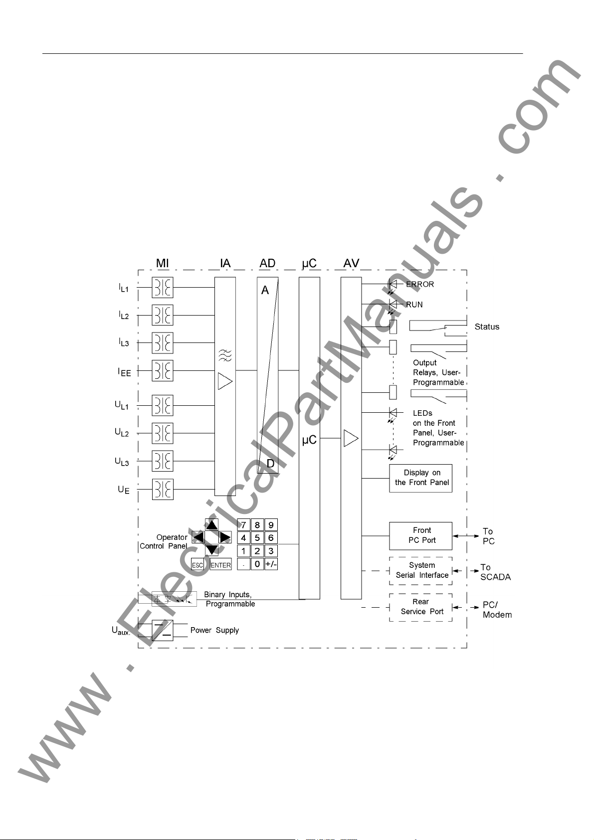
The digital Multi-Function Protection SIPROTEC® 7UM61 is equipped with a high performance microprocessor. All tasks such as the acquisition of the measured values
and issuing of commands to circuit breakers and other switching equipment, are processed digitally. Figure 1-1 shows the basic structure of the device.
Analog Inputs The measuring inputs (MI) are galvanically isolated, transform the currents and volt-
ages from the primary transformers and adapt them to the internal processing level of
the device. The device has 4 current and 4 voltage inputs. Three inputs are used on
each side of the protected object for measuring of the phase currents.
Figure 1-1 Hardware Structure of the Digital Machine Protection Device 7UM61 (maximum configuration)
1 current input is equipped with sensitive input transformers (IEE) and can measure
secondary currents in the mA range. 3 voltage inputs acquire the phase-to-earth voltages (connection to phase-to-phase voltages and voltage transformers in V connec-
18
7UM61 Manual
C53000-G1176-C127-3
Page 19

1.1 Overall Operation
www . ElectricalPartManuals . com
tion is possible as well). The 4th voltage input is for displacement voltage measurement for stator earth fault protection.
The IA input amplifier group allows high impedance connection for analog input values
and contains filters optimized for measured value processing bandwidth and speed.
The AD analog digital converter group contains high resolution Σ∆ digital converters
(22 bits) and memory components for data transfer to the microcomputer.
Microcomputer System
Adaptation of Sampling Frequency
The implemented software is processed in the microcomputer system (µC). Essential
functions are:
• Filtering and conditioning of the measured signals,
• Continuous monitoring of the measured quantities
• Monitoring of the pickup conditions for the individual protective functions
• Querying of limit values and time sequences,
• Control of signals for logical functions,
• Decision for trip commands
• Signalling of protection behaviour via LEDs, LCD, relays or serial interfaces
• Storage of indications, fault data and fault values for fault analysis,
• Management of the operating system and its associated functions such as data recording, real-time clock, communication, interfaces, etc.
The frequency of the measured quantities is continuously measured and used for adjusting of the actual sampling frequency. This ensures that the protection and measurement functions produce correct results over a wide frequency range. This ensures
measuring accuracy in the frequency range from 11 Hz to 69 Hz.
The sampling frequency adaptation can, however, operate only when at least one a.c.
measured quantity is present at one of the analog inputs, with an amplitude of at least
5 % of rated value (“operational condition 1”).
If no suitable measured values are present, or if the frequency is below 11 Hz or above
70 Hz, the device operates in mode “operational condition 0”.
Binary Inputs and Outputs
F r o n t E l em e n ts Optical indicators (LEDs) and a front display panel (LC display) provide information on
7UM61 Manual
C53000-G1176-C127-3
Binary inputs and outputs from and to the computer system are routed via the I/O
modules (inputs and outputs). The computer system obtains the information from the
system (e.g remote resetting) or the external equipment (e.g. blocking commands).
Outputs are mainly commands that are issued to the switching devices and messages
for remote signalling of events and states.
the function of the device and indicate events, states and measured values. Integrated control and numeric keys in conjunction with the LCD facilitate local interaction with
the device. By this means all information on the device such as design and setting parameters, operation and disturbance indications and measured values can be queried,
(see also SIPROTEC
changed.
®
System Description /1/), and setting parameters can be
19
Page 20

1 Introduction
www . ElectricalPartManuals . com
S e r i a l I n t e r f a c e s A serial operator interface in the front cover is provided for local communication with
a PC, using the operating program DIGSI
functions of the device.
A serial service
possible using DIGSI
devices to the PC or for operation via a modem. The service interface can be also
used for connecting a RTD-Box (see chapter 2.32)
All data can be transferred to a central control or monitoring system via the serial
system
transmission modes to suit the particular application.
A further interface is provided for time synchronization
ternal synchronization sources.
Further communication protocols can be implemented via additional communication
protocols.
Power Supply The functional units described are supplied by a power supply PS with the necessary
power in the different voltage levels. Voltage dips may occur if the voltage supply
system (substation battery) becomes short-circuited. Usually, they are bridged by a
capacitor (see also Technical Data).
interface. This interface may be provided with various protocols and physical
interface can likewise make communication via PC with the device
®
4. This is especially well suited for dedicated connection of the
®
4. This permits convenient operation of all
of the internal clock through ex-
20
7UM61 Manual
C53000-G1176-C127-3
Page 21
1.2 Application Scope
www . ElectricalPartManuals . com
The SIPROTEC® 7UM61 device is a digital multi-function machine protection unit from
the 7UM6 Numerical Protection series. It provides all functions necessary for protection of generators and motors. As the scope of functions of the 7UM61 can be customized, it is suited for small, medium-sized and large generators.
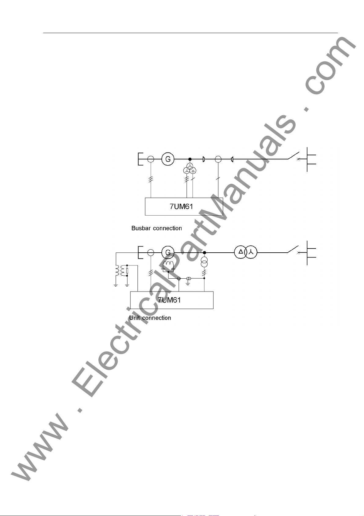
The device fulfills the protection requirements for the two typical basic connections:
• Busbar connection
• Unit connection
1.2 Application Scope
Figure 1-2 Typical Connections
The scalable software allows a wide range of applications. Corresponding function
packages can be selected for each particular application. For instance, alone with the
7UM61 device, it is possible to provide comprehensive and reliable protection of generators from small to medium capacity (approx. 0.5 - 5 MW).
Additionally, the device forms the basis for the protection of medium to large size generators (backup protection). In combination with the 7UM62 device (a further device
of the 7UM6 series), all protection requirements encountered in practice for the smallest to the largest machines can be met. This makes possible a consistent concept for
reserve protection capacity.
7UM61 Manual
C53000-G1176-C127-3
21
Page 22

1 Introduction
www . ElectricalPartManuals . com
The 7UM61 device is usable for further applications such as
• Backup protection, since in addition to overcurrent protection, a large variety of protection functions allow, for example, monitoring of voltage and frequency load.
• Protection of synchronous and asynchronous motors.
• Mains Decoupling Device
Messages and Measured Values; Recording of Event
and Fault Data
Communication For communication with external operator, control and storage systems, serial inter-
Operator Interface on the Front Panel
The operating messages provide information about conditions in the power system
and the device itself. Measurement quantities and resulting computed values can be
displayed locally and communicated via the serial interfaces.
Annunciations of the devices can be presented by LEDs on the front panel (allocatable), processed further externally using output contacts (allocatable), combined with
user-definable logic functions and/or output via serial interfaces (see Communication
below).
During a generator or network fault (fault in the power system), important events and
state changes are stored in a fault annunciation buffer. The instantaneous or rms measured values during the fault are also stored in the device and are subsequently available for fault analysis.
faces are available.
A 9-pin DSUB socket on the front panel is used for local communication with a personal computer. By means of the SIPROTEC
and evaluation tasks can be executed via this user
modifying configuration parameters and settings, configuring user-specific logic functions, retrieving operational and fault messages and measured values, readout and
display of fault recordings, querying of devices statuses and measured values.
®
operating software DIGSI®, all operational
interface, such as specifying and
Rear Panel Interfaces
Depending on the individual ordering variant, additional interfaces are located on the
rear panel of the device. These interfaces allow an extensive communication with
other digital operating, control and memory components to be set up:
The service
nected to this interface. For this reason, remote operation is possible via PC and the
DIGSI
The system
control centre. The data cables or fibre optic cables can be used. Several standard
protocols are available for data transmission:
• IEC 60 870–5–103
Integration of the devices into the substation automation systems SINAUT
and SICAM
• Profibus DP
This protocol of automation technology allows transmission of indications and measured values.
• Modbus ASCII/RTU
This protocol of automation technology allows transmission of indications and measured values.
•DNP 3.0
This protocol of automation technology allows transmission of indications and measured values.
interface can be operated through data lines. Also, a modem can be con-
®
4 operating software, e.g. to operate several devices from a central PC.
interface is used for central communication between the device and a
®
®
can also be done with this profile.
LSA
22
7UM61 Manual
C53000-G1176-C127-3
Page 23

1.3 Characteristics
www . ElectricalPartManuals . com
General Features • Powerful 32-bit microprocessor system.
• Complete digital processing of measured values and control, from sampling and
digitalization of measured quantities to tripping circuit breakers or other switchgear
devices.
• Total electrical separation between the internal processing stages of the device and
the external transformer, control and DC supply circuits of the system because of
the design of the binary inputs, outputs, and the DC converters.
1.3 Characteristics
Definite Time Overcurrent Protection
(I>) with Undervoltage Seal-In
• Simple device operation using the integrated operator and display panel or by
means of a connected PC running DIGSI
• Continuous computation and display of measured quantities.
• Storage of fault messages and instantaneous or rms values for fault recording.
• Continuous monitoring of measured values as well as of the hardware and software
of the device.
• Communication with central control and memory storage equipment via serial interfaces, optionally via data cable, modem, or optic fibre lines.
• Battery-buffered clock that can be synchronized with an IRIG-B (via satellite) or
DCF77 signal, binary input signal, or system interface command.
• Statistics: Recording of the number of trip signals instigated by the device and
logging of currents switched off last by the device, as well as accumulated shortcircuit currents of each pole of the circuit breaker.
• Operating Hours Counter: Tracking of operating hours of the equipment under load
being protected.
• Commissioning aids such as connection check, field rotation check, status display
of all binary inputs and outputs, and test measurement recording.
• 2 definite time stages I> and I>> for the 3 phase currents (I
• Undervoltage seal-in for synchronous machines whose excitation voltage is obtained from the machine terminals;
• Optionally additional directional determination with the high current stage I>>.
®
4.
, IL2, IL3).
L1
• Blocking capability e.g. for reverse-interlocking bus-bar protection with any stage.
Inverse Time Overcurrent Protection
(voltage-controlled)
Thermal Overload Protection
7UM61 Manual
C53000-G1176-C127-3
• Selection possible from various characteristics (IEC, ANSI).
• Optionally voltage-controlled or voltage-dependent alteration of current pick-up behaviour during undervoltage;
• Voltage influencing can be blocked by fuse failure monitor or via voltage transformer
protective circuit breaker.
• Temperature image of current heat losses (overload protection with full memory capability, single body thermal model).
• Additional adjustable warning levels based on temperature rise and current magnitude.
• Consideration of coolant and ambient temperatures possible.
23
Page 24

1 Introduction
www . ElectricalPartManuals . com
Negative Sequence Protection
Underexcitation protection
Reverse Power Protection
Forward Power Supervision
• Precise evaluation of negative sequence component of the three phase currents.
• Alarm stage when a set unbalanced load is exceeded.
• Thermal characteristic with adjustable negative sequence factor and adjustable
cooldown time.
• High-speed trip stage for large unbalanced loads (can be used for short-circuit protection).
• Conductance measurement from positive sequence components.
• Multi-step characteristic for steady-state and dynamic stability limits;
• Consideration of excitation voltage (only via binary input).
• Calculation of power from positive sequence components.
• Highly sensitive and precise active power measurement (detection of small motor-
ing powers even with low power factor cos ϕ , angle error compensation).
• Insensitive to power fluctuations.
• Long-time stage and short-time stage (active with closed emergency tripping valve).
• Calculation of power from positive sequence components.
• Supervision of over-power (P>) and/or under-power (P<) of active power output
with individually adjustable power limits.
Impedance protection
Undervoltage Protection
Overvoltage Protection
Frequency Protection
Overexcitation Protection
• Optionally high-speed or high-accuracy measurement.
• Overcurrent pickup with undervoltage seal-in (for synchronous machines which
take their excitation voltage from the terminals).
• 2 impedance zones, 1 overreach zone (switchable via binary input), 4 time stages.
• Polygonal tripping characteristics;
• Two-stage undervoltage measurement of positive sequence component of voltages.
• Two-stage overvoltage measurement of the highest of the three voltages.
• Optionally with phase-to-phase voltages or phase-to-earth voltages.
• Monitoring on undershooting (f<) and/or overshooting (f>) with 4 frequency limits
and delay times that are independently adjustable.
• Insensitive to harmonics and abrupt phase angle changes.
• Settable undervoltage threshold.
• Calculation of the ratio U/f.
• Adjustable warning and tripping stage.
• Standard characteristic or arbitrary trip characteristic for calculation of the thermal
stress, selectable.
24
7UM61 Manual
C53000-G1176-C127-3
Page 25

1.3 Characteristics
www . ElectricalPartManuals . com
Rate-of-FrequencyChange Protection
Vector Jump • Sensitive phase jump detection to be used for network disconnection.
90% Stator Earth Fault Protection
Sensitive Earth F a u l t P r o t e c t i o n
• Monitors whether the frequency overshoots (df/dt>) and/or undershoots (df/dt<) a
set limit value, with 4 individually settable limit values or delay times.
• Variable measuring windows
• Coupling to frequency protection pickup.
• Settable undervoltage threshold.
• Suitable for generators in unit connection and directly connected to busbars.
• Measurement of displacement voltage via the neutral or earthing transformer or by
calculation from phase-to-earth voltages.
• Highly sensitive earth current detection, optional with or without directional determination with zero sequence components (I
• Directional characteristic adjustable.
• Determination of the earth-faulted phase.
• Two-stage earth fault current measurement: I
• High sensitivity (adjustable on the secondary side from 2 mA).
• Can be used for stator earth fault or rotor earth fault detection.
, U0).
0
EE
>> and IEE>.
100% Stator Earth Fault Protection w i t h 3 r d H a r m o n i c
Motor Starting Time Supervision
Restart Inhibit for Motors
Breaker Failure Protection
• Measurement circuit monitoring for minimum current flow when used for rotor earth
fault protection.
• Detection of the 3rd harmonic of the voltage at the starpoint or broken delta winding
of an earthing transformer.
• In addition to the 90-%-stator earth fault protection there is a protection of the entire
stator winding (protective range 100 %).
• Inverse time overcurrent tripping based on an evaluation of the motor starting
current
• Inverse time delay with blocked rotor.
• Approximate computation of rotor overtemperature.
• Motor switchon is enabled only a if a restartup limit is undershot.
• Calculation of waiting time until automatic reclosure is enabled.
• Different prolongation of cooldown time constants for standstill/operation period is
taken into consideration.
• Possibility for disabling the start inhibit if emergency startup is required.
• By checking the current or evaluation of the breaker auxiliary contacts.
• Initiation of each integrated protection function allocated to the circuit breaker.
• Initiation possible through a binary input from an external protective device.
7UM61 Manual
C53000-G1176-C127-3
25
Page 26

1 Introduction
www . ElectricalPartManuals . com
Inadvertent Energizing Protection
Threshold Supervisions
Temperature Detection by Thermoboxes
Phase Sequence Inversion
User-Defined Functions
• Damage limitation on inadvertent switching on of a stationary generator by fast
opening of the generator switch.
• Instantaneous value acquisition of the phase currents.
• Operational state and voltage supervision as well as fuse failure monitor are the
enable criteria.
• 6 freely assignable indications for threshold supervision.
• Implementation of fast supervision tasks with CFC.
• Acquisition of any ambient temperatures or coolant temperatures using thermoboxes and external temperature sensors.
• Selectable L1, L2, L3 or L1, L3, L2 via setting (static) or binary input (dynamic).
• Internal and external signals can be logically combined to establish user-defined
logic functions.
• All common logic functions (AND, OR, NOT, Exclusive OR, etc.).
• Time delays and limit value interrogations.
• Processing of measured values, including zero suppression, adding a knee characteristic for a transducer input, and live-zero monitoring.
Breaker Control • Circuit breakers can be opened and closed manually via programmable function
Measured Values Monitoring
keys, via the system interface (e.g. by SICAM
face (using a PC with DIGSI
• Feedback information on circuit breakers states via the breaker auxiliary contacts.
• Plausibility monitoring of the circuit breaker positions and interlocking conditions for
switching.
• Increased reliability thanks to monitoring of internal measuring circuits, of auxiliary
power supply, and of hardware and software.
• Current transformer and voltage transformer secondary circuits are monitored
using symmetry checks.
• Trip circuit monitoring possible via external circuitry.
• Phase sequence check.
■
®
).
®
or LSA), or via the operating inter-
26
7UM61 Manual
C53000-G1176-C127-3
Page 27
Functions 2
www . ElectricalPartManuals . com
This chapter describes the numerous functions available on the SIPROTEC® 4
7UM61. It shows the setting possibilities for all the functions in maximum configuration. Instructions for deriving setting values and formulae, where required are provided.
Additionally it may be defined which functions are to be used.
2.1 Introduction, Reference Systems 29
2.2 Functional Scope 31
2.3 Power System Data 1 34
2.4 Change Group 39
2.5 Power System Data 2 40
2.6 Definite-Time Overcurrent Protection (I>, ANSI 50/51) with Undervoltage
Seal-In 42
2.7 Definite-Time Overcurrent Protection (I>>, ANSI 50, 51, 67) with Direction
Detection 46
2.8 Inverse-Time Overcurrent Protection (ANSI 51V) 52
2.9 Thermal Overload Protection (ANSI 49) 59
2.10 Unbalanced Load (Negative Sequence) Protection (ANSI 46) 70
2.11 Underexcitation (Loss-of-Field) Protection (ANSI 40) 77
2.12 Reverse Power Protection (ANSI 32R) 85
2.13 Forward Active Power Supervision (ANSI 32F) 89
2.14 Impedance Protection (ANSI 21) 92
2.15 Undervoltage Protection (ANSI 27) 103
2.16 Overvoltage Protection (ANSI 59) 106
2.17 Frequency Protection (ANSI 81) 109
2.18 Overexcitation (Volt/Hertz) Protection (ANSI 24) 113
2.19 Rate-of-Frequency-Change Protection df/dt (ANSI 81R) 118
2.20 Jump of Voltage Vector 123
2.21 90-%-Stator Earth Fault Protection (ANSI 59N, 64G, 67G) 128
2.22 Sensitive Earth Fault Protection (ANSI 51GN, 64R) 136
C53000-G1176-C127-3
277UM61 Manual
Page 28

2 Functions
www . ElectricalPartManuals . com
2.23 100-%-Stator Earth Fault Protection with 3rd Harmonics
(ANSI 27/59TN 3rd Harm.) 140
2.24 Motor Starting Time Supervision (ANSI 48) 144
2.25 Restart Inhibit for Motors (ANSI 66, 49Rotor) 149
2.26 Breaker Failure Protection (ANSI 50BF) 157
2.27 Inadvertent Energization (ANSI 50, 27) 162
2.28 Measurement Supervision 166
2.29 Trip Circuit Supervision 176
2.30 Threshold supervision 183
2.31 External Trip Functions 189
2.32 RTD-Box 192
2.33 Phase Rotation Reversal 201
2.34 Protection Function Control 203
2.35 Ancillary Functions 208
2.36 Command Processing 221
28
7UM61 Manual
C53000-G1176-C127-3
Page 29
2.1 Introduction, Reference Systems
www . ElectricalPartManuals . com
2.1 Introduction, Reference Systems
The following chapters explain the individual protective and additional functions and
provide information about the setting values.
2.1.1 Functional Description
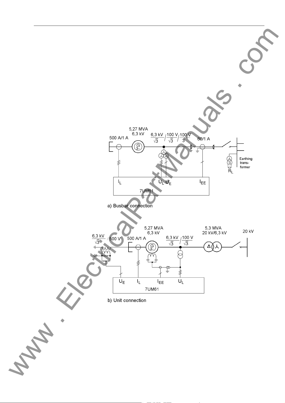
Generator The calculation examples are based on two smaller capacity reference power systems
with the two typical basic connections, i.e. the busbar connection and the unit connection (see following figure). All default settings of the relay are adapted accordingly.
Figure 2-1 Reference Systems
7UM61 Manual
C53000-G1176-C127-3
29
Page 30

2 Functions
www . ElectricalPartManuals . com
Technical Data of the Reference Power Systems
Generator S
Current transformer: I
Toroidal c.t.: I
Voltage transformer: U
Transformer
Transformer: S
Zero point transformer:
= 5.27 MVA
N, T
= 6.3 kV
U
N, Gen
ING = 483 A
cos ϕ = 0.8
= 500 A; I
N,prim
= 60 A; I
N,prim
=(6.3/√3) kV U
N, prim
= 5.3 MVA
N, T
UOS = 20 kV
U = 6.3 kV
= 7 %
u
K
CT=
= 1 A
N, sec
= 1 A
N, sec
= (100/√3) V
N, sec
/3 = (100/3) V
U
en
Resistor divider: 5 : 1
Motor
Motor VN = 6600 V
I
= 126 A
N, M
I
I
T
Current transformer: I
= 624 A (Starting current)
StartCurr.
= 135 A (Permissible continuous stator cur-
max
= 8.5 s (Starting time at ISTRT)
STRT
= 200 A; I
N,prim
Further technical data are provided within the framework of the functional setting
specifications of the individual protective functions.
The calculated setting values are secondary setting values related to the device and
can be modified immediately by way of local operation.
For a complete reparametrization the operating program DIGSI
In this way, the user can specify primary values in addition to secondary settings. This
is done in the 7UM61 as a setting referred to the rated values of the object to be protected (e.g. I
N, G
dent, typical settings of the protective functions can be pre-specified. The data of the
individual power system are updated in the Power System Data 1 or Power
System Data 2 and conversion to secondary values is done by mouse clicking. All
necessary conversion formulas of the individual functions are stored in the operating
program.
; U
N, G
rent)
= 1 A
N, sec
®
4 is recommended.
; S
). This procedure has the advantage that system-indepen-
N, G
30
7UM61 Manual
C53000-G1176-C127-3
Page 31

2.2 Functional Scope
www . ElectricalPartManuals . com
The 7UM61 device has numerous protection and supplementary functions. The hardware and firmware provided is designed for this scope of functions. Nevertheless a
few restrictions apply to the use of the earth fault current and earth fault voltage inputs
UE and IEE respectively. The same input can not be simultaneously fed with different
measured values, e.g. for rotor earth fault protection and stator earth fault protection.
In addition the command functions can be matched to the system conditions. Also individual functions can be enabled or disabled during configuration. Functions not
needed can be thus be deactivated.
The available protection and supplementary functions can be configured as Enabled
or Disabled. For some functions a choice between several alternatives is possible, as
described below.
Functions configured as disabled are not processed by the 7UM61. There are no indications, and corresponding settings (functions, limit values) are not displayed during
setting.
2.2 Functional Scope
2.2.1 Functional Description
Configuration of the Functional Scope
Configuration settings can be entered using a PC and the software program DIGSI
and transferred via the front serial port or the rear service interface. Operation is described in the SIPROTEC
For changing configuration parameters in the device, password no.7 is required (for
parameter set). Without the password, the settings may be read, but may not be modified and transferred to the device.
Functional scope and as the case may be possible alternatives are adapted to the
power system conditions in the Function Scope dialog box.
Note
Available functions and default settings depend on the ordered device variant (see Appendix for details). Also, not all combinations of protective functions are possible
because of certain restrictions imposed by the hardware (see Section 2.2.2).
2.2.2 Setting Notes
®
System Description /1/.
®
Special Cases Most settings are self-explanatory. The special cases are described below.
If use of the setting group change function is desired, address 103 Grp Chge
OPTION should be set to Enabled. In this case, it is possible to apply two groups of
settings for function parameters (refer also to Section 2.4) allowing convenient and
fast switch-over between these setting groups. Only one function parameter group
may be selected and used if the setting is Disabled.
7UM61 Manual
C53000-G1176-C127-3
31
Page 32
2 Functions
www . ElectricalPartManuals . com
Parameter 104 FAULT VALUE is used to specify whether the oscillographic fault recording should record Instant. values or RMS values. If RMS values is stored,
the available recording time increases by the factor 16.
For the high-current stage I>> of the overcurrent protection, address 113O/C PROT.
I>> determines whether Non-Directional or directional is to be operative. By
selecting Disabled, this overcurrent stage can be excluded altogether. With inverse
time overcurrent protection 114O/C PROT. Ip, depending on the ordered variant,
various characteristics are available for selection, in accordance with IEC or ANSI
standard. Selecting 'disabled' deconfigures inverse time overcurrent protection.
For earth fault protection, Address 150 S/E/F PROT. presents the options non-
dir. U0, non-dir. U0&I0 and directional, unless the whole function is
Disabled. The first option evaluates only the displacement voltage (to be used with
unit connection). The second option evaluates in addition to the displacement voltage,
the magnitude of the earth fault current (or the difference between the starpoint current
and the total current of a toroidal CT in busbar systems with low-ohmic switchable starpoint resistors). The third option considers as a further criterion the direction of the
earth fault current if with machines in busbar connection the magnitudes of displacement voltage and earth fault current alone are not sufficient to distinguish between
system earth faults and machine earth faults.
For trip circuit monitoring, address 182 Trip Cir. Sup. is used to specify whether
two binary inputs (2 Binary Inputs) or only one (1 Binary Input) should be
utilized.
2.2.3 Settings
Addr. Parameter Setting Options Default Setting Comments
103 Grp Chge OPTION Disabled
Enabled
104 FAULT VALUE Disabled
Instant. values
RMS values
112 O/C PROT. I> Disabled
Enabled
113 O/C PROT. I>> Disabled
directional
Non-Directional
114 O/C PROT. Ip Disabled
with IEC
with ANSI
116 Therm.Overload Disabled
Enabled
117 UNBALANCE LOAD Disabled
Enabled
130 UNDEREXCIT. Disabled
Enabled
131 REVERSE POWER Disabled
Enabled
132 FORWARD POWER Disabled
Enabled
133 IMPEDANCE PROT. Disabled
Enabled
Disabled Setting Group Change Option
Instant. values Fault values
Enabled Overcurrent Protection I>
Non-Directional Overcurrent Protection I>>
Disabled Inverse O/C Time Protection
Enabled Thermal Overload Protection
Enabled Unbalance Load (Negative Se-
quence)
Enabled Underexcitation Protection
Enabled Reverse Power Protection
Enabled Forward Power Supervision
Enabled Impedance Protection
32
7UM61 Manual
C53000-G1176-C127-3
Page 33
2.2 Functional Scope
www . ElectricalPartManuals . com
Addr. Parameter Setting Options Default Setting Comments
140 UNDERVOLTAGE Disabled
Enabled
141 OVERVOLTAGE Disabled
Enabled
142 FREQUENCY Prot. Disabled
Enabled
143 OVEREXC. PROT. Disabled
Enabled
145 df/dt Protect. Disabled
2 df/dt stages
4 df/dt stages
146 VECTOR JUMP Disabled
Enabled
150 S/E/F PROT. Disabled
non-dir. U0
non-dir. U0&I0
directional
151 O/C PROT. Iee> Disabled
Enabled
152 SEF 3rd HARM. Disabled
Enabled
165 STARTUP MOTOR Disabled
Enabled
166 RESTART INHIBIT Disabled
Enabled
170 BREAKER FAILURE Disabled
Enabled
171 INADVERT. EN. Disabled
Enabled
180 FUSE FAIL MON. Disabled
Enabled
181 M.V. SUPERV Disabled
Enabled
182 Trip Cir. Sup. Disabled
2 Binary Inputs
1 Binary Input
185 THRESHOLD Disabled
Enabled
186 EXT. TRIP 1 Disabled
Enabled
187 EXT. TRIP 2 Disabled
Enabled
188 EXT. TRIP 3 Disabled
Enabled
189 EXT. TRIP 4 Disabled
Enabled
190 RTD-BOX INPUT Disabled
Port C
Port D
Port E
191 RTD CONNECTION 6 RTD simplex
6 RTD HDX
12 RTD HDX
Enabled Undervoltage Protection
Enabled Overvoltage Protection
Enabled Over / Underfrequency Protection
Enabled Overexcitation Protection (U/f)
2 df/dt stages Rate-of-frequency-change protec-
tion
Enabled Jump of Voltage Vector
non-dir. U0&I0 Stator Earth Fault Protection
Enabled Sensitive Earth Current Protection
Enabled Stator Earth Fault Prot. 3rd Har-
monic
Enabled Motor Starting Time Supervision
Enabled Restart Inhibit for Motors
Enabled Breaker Failure Protection
Enabled Inadvertent Energisation
Enabled Fuse Failure Monitor
Enabled Measured Values Supervision
Disabled Trip Circuit Supervision
Enabled Threshold Supervision
Enabled External Trip Function 1
Enabled External Trip Function 2
Enabled External Trip Function 3
Enabled External Trip Function 4
Disabled External Temperature Input
6 RTD simplex Ext. Temperature Input Connec-
tion Type
7UM61 Manual
C53000-G1176-C127-3
33
Page 34
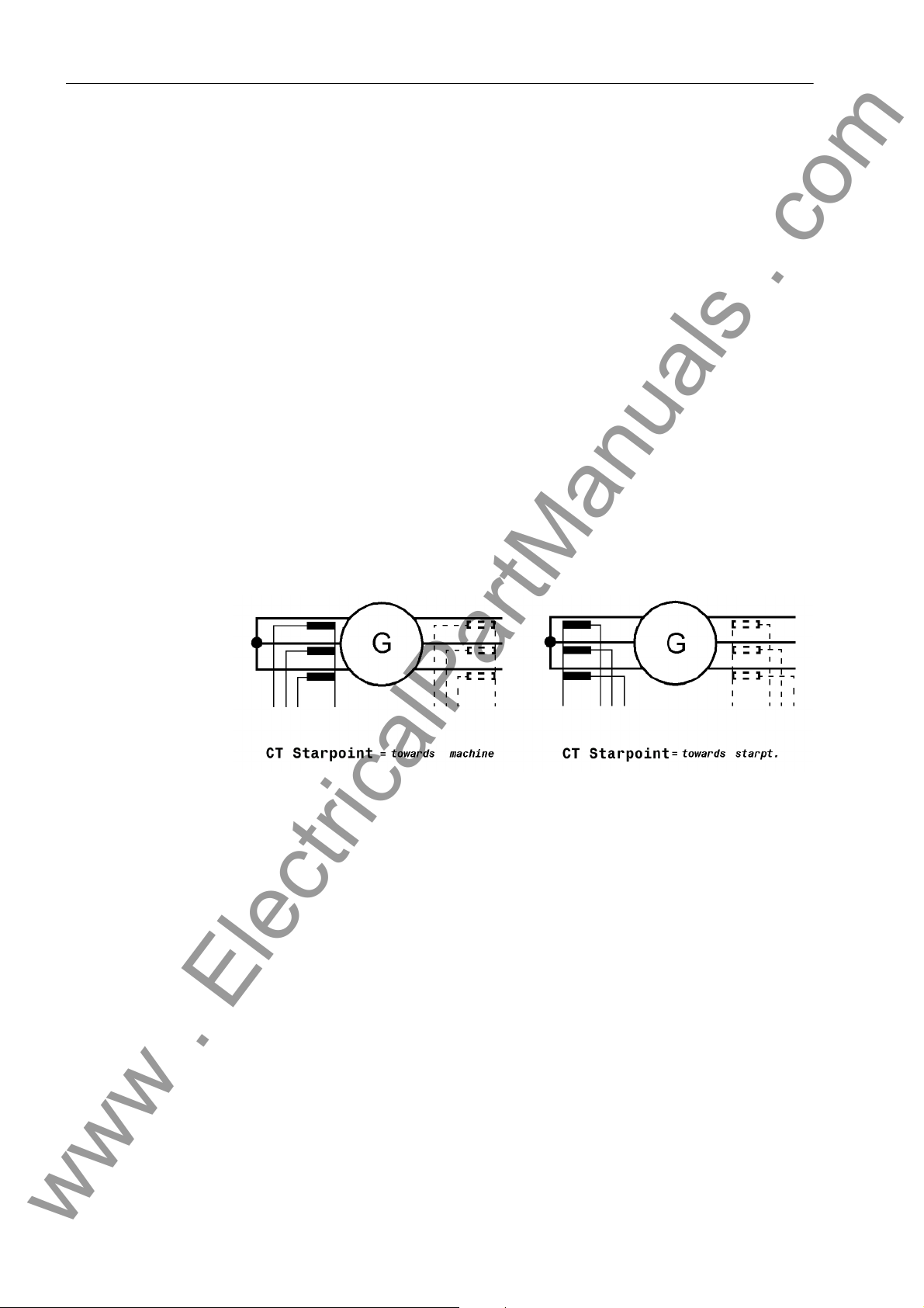
2 Functions
www . ElectricalPartManuals . com
2.3 Power System Data 1
The device requires certain network and power system data so that it can be adapted
to its intended functions in accordance with application. These include, for instance,
rated power system and transformer data, measured quantity polarities and connection, breaker properties etc. There are also certain parameters common to all functions, i.e. not associated with a specific protection, control or monitoring function.
Section P.System Data 1 describes these.
2.3.1 Setting Notes
General The Power System Data 1 can be changed via the operator or service interface from
a PC using DIGSI
®
double-click Settings to display the data available.
Connection of the
Current Transformer Set
Nominal Values of the Transformers
In DIGSI
In address 210 CT Starpoint the polarity of the current transformers must be entered, i.e. the location of the CT starpoint. This setting determines the measuring direction of the device (forwards = line direction). The following figure shows the definition even in cases where there are no starpoint CTs.
Figure 2-2 Location of the CT Starpoints
At addresses 211 CT PRIMARY and 212 CT SECONDARY, information is entered regarding the primary and secondary current rating of the current transformers. It is important to ensure that the rated secondary current of the current transformer matches
the rated current of the device, otherwise the device will incorrectly calculate primary
data.
®
.
W0 Correction Angle
34
A correction of the angle faults of the current and voltage transformers is particularly
important with regard to reverse power protection, as in this case a very low active
power is computed from a very high apparent power (for small cos ϕ).
At address 204 CT ANGLE W0 a constant correction angle can be entered for the CT.
The angle fault difference ∆ϕ between the current and voltage transformers is partic-
ularly important in this context. As a correction, the sum of the mean angle errors of
the current transformers and voltage transformers is set. The corrective value can be
determined during machine commissioning (see Section Mounting and Commissioning).
7UM61 Manual
C53000-G1176-C127-3
Page 35
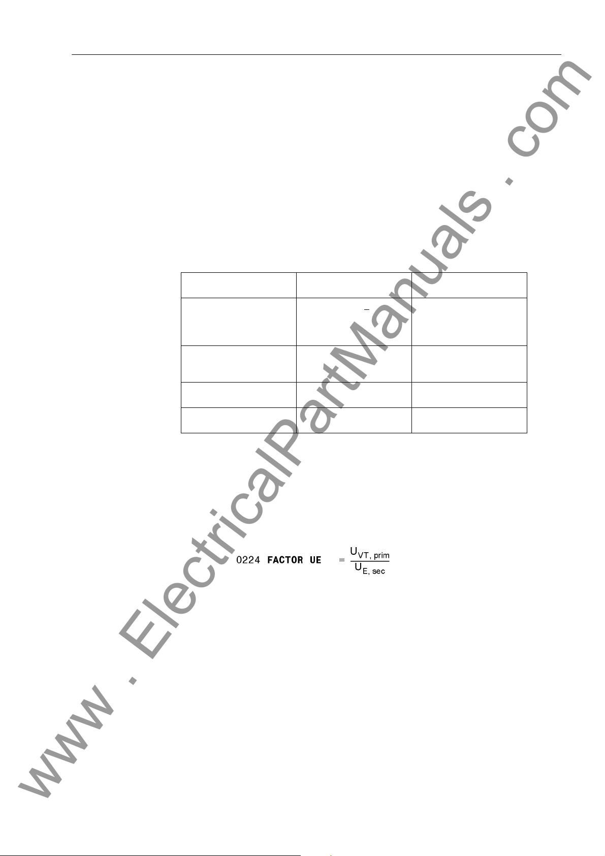
2.3 Power System Data 1
www . ElectricalPartManuals . com
Iee Transformation Ratios
Nominal Values of
Voltage Transformers
Voltage Connection U
E
For conversion of the ground current Iee in primary quantities, the device requires the
primary/secondary transformation ratio of the transformer. This is set at address 213
FACTOR IEE.
At addresses 221 Unom PRIMARY and 222 Unom SECONDARY, information is entered
regarding the primary nominal voltage and secondary nominal voltages (phase-tophase) of the connected voltage transformers.
At address 223 UE CONNECTION the user specifies to the device which type of
voltage is connected to the UE input. The device establishes from this information how
to process the input signal. The following table shows the interdependencies for each
protection function.
Table 2-1 Setting Options for the UE Input and their Impact on the Protection Functions
Setting for UE CONNEC-
TION (Addr. 0223)
not connected Processing of U0 computed
UE connected to any transformer
UE connected to broken
delta winding
UE connected to neutral
transformer
90% Stator Earth Fault
Protection
value (exactly: √3 U0)
Processing of UE input
(e.g. earth fault protection
on transformer side)
Processing of UE input Processing of UE input
Processing of UE input Processing of UE input
Stator Earth Fault Protec-
tion with 3rd Harmonic
The 3rd harmonic is determined from the computed
U0 voltage (U0 3rd harm >
stage only usable).
–
UE Transformation Ratio
For conversion of the displacement voltage UE to primary quantities, the device requires the primary/secondary transformation ratio of the transformer delivering the UE
voltage. With the exception of the rotor earth fault protection, the 224 FACTOR UE has
an impact on those protection functions which process the UE input directly, as shown
in Table 2-1. For this ratio224 FACTOR UE the following generally applies:
In this context, U
is the secondary displacement voltage applied to the device. If a voltage divider
U
E, sec
is used, its division ratio also influences this factor. The following equation results for
the example in Section 2.1, unit transformer connection figure, with the power system
data selected there and an 1:5 voltage divider ratio
is the primary voltage (generally phase-ground voltage) and
VT, prim
7UM61 Manual
C53000-G1176-C127-3
35
Page 36
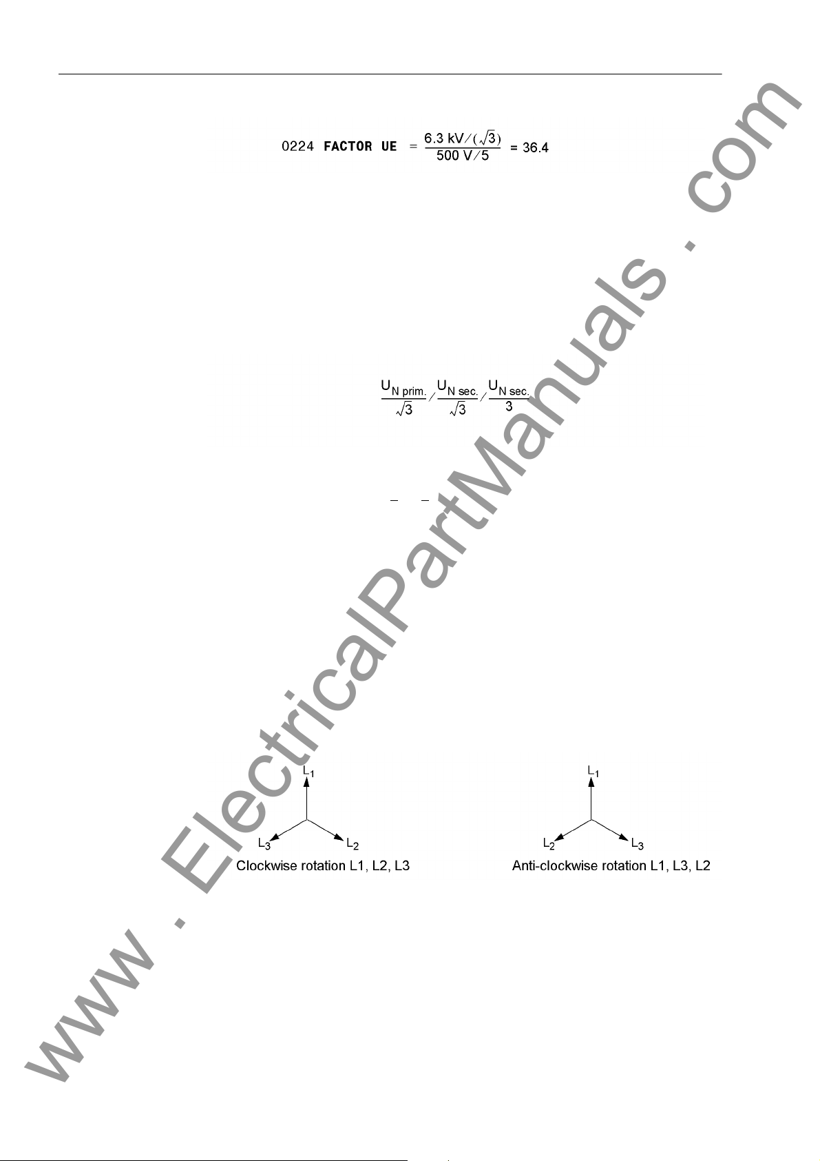
2 Functions
www . ElectricalPartManuals . com
Uph/Uen Adaption Factor
Rated System Frequency
The address 225 serves to communicate the adaptation factor between the phase
voltage and the displacement voltage to the device. This information is relevant for
measured quantity monitoring.
If the voltage transformer set has e-n windings connected to the device (UE input), this
must be specified accordingly in address 223 (see above margin heading "UE Input").
Since transformation between voltage transformers usually is as follows:
with connected Uen voltage the Uph/Uen factor (secondary voltage, address 225 Uph
/ Udelta) must be set to 3/√3
formation of the displacement voltage via an interconnected transformer set, the factor
must be corrected accordingly.
The nominal frequency of the system is set in Address 270 Rated Frequency. The
factory setting of the model variant must only be changed if the device is to be used
for a purpose other than intended when ordering.
= √3 = 1.73. For other transformation ratios, i.e. the
Phase Rotation Address 271 PHASE SEQ. is used to change the default phase sequence (L1 L2 L3
for clockwise rotation), if your power system permanently has an anti-clockwise phase
sequence (L1 L3 L2). A temporary reversal of rotation is also possible using binary
inputs (see Section 2.33).
Figure 2-3 Phase sequences
Operating Mode The 272 SCHEME setting is used for specifying if the generator to be protected is op-
erated in Unit transf. or in Busbar mode. This specification is important for stator
earth fault connection and for the inverse O/C time protection with undervoltage consideration, as different voltages are used here, depending on the corresponding operating mode (see "Undervoltage Consideration" in Section 2.8).
36
7UM61 Manual
C53000-G1176-C127-3
Page 37
2.3 Power System Data 1
www . ElectricalPartManuals . com
ATEX100 Parameter 274 ATEX100 allows compliance with PTB requirements (special require-
ments in Germany) for thermal replicas. If this parameter is set to YES, all thermal replicas of the 7UM61 are stored on auxiliary power supply failure. As soon as the supply
voltage returns, the thermal replicas continue operating with the stored values. If the
parameter is set to NO, the calculated overtemperature values of all thermal replicas
are reset to zero on auxiliary power supply failure.
Command Duration Address 280 is used to set the minimum time TMin TRIP CMD the tripping contacts
will remain closed. This setting applies to all protective functions that initiate tripping.
Current Flow Monitoring
Address 281 BkrClosed I MIN corresponds to the threshold value of the integrated
current flow monitoring feature. This setting is used for the elapsed-time meter and the
overload protection. If the set threshold current is exceeded, the circuit breaker is considered closed and the power system is considered to be in operation. In the case of
overload protection, this criterion distinguishes between standstill and motion of the
machine to be protected.
2.3.2 Settings
Addresses which have an appended "A" can only be changed with DIGSI, under Additional Settings.
The table indicates region-specific presettings. Column C (configuration) indicates the
corresponding secondary nominal current of the current transformer.
Addr. Parameter C Setting Options Default Setting Comments
204 CT ANGLE W0 -5.00 .. 5.00 ° 0.00 ° Correction Angle CT W0
210 CT Starpoint towards machine
towards starpt.
211 CT PRIMARY 10 .. 50000 A 500 A CT Rated Primary Current
212 CT SECONDARY 1A
5A
towards machine CT Starpoint
1A CT Rated Secondary
Current
213 FACTOR IEE 1.0 .. 300.0 60.0 CT Ratio Prim./Sec. Iee
221 Unom PRIMARY 0.10 .. 400.00 kV 6.30 kV Rated Primary Voltage
222 Unom SECONDARY 100 .. 125 V 100 V Rated Secondary Voltage
(Ph-Ph)
223 UE CONNECTION neutr. transf.
broken delta
Not connected
any VT
224 FACTOR UE 1.0 .. 2500.0 36.4 VT Ratio Prim./Sec. Ue
225A Uph / Udelta 1.00 .. 3.00 1.73 Matching Ratio Ph.-VT to
270 Rated Frequency 50 Hz
60 Hz
271 PHASE SEQ. L1 L2 L3
L1 L3 L2
272 SCHEME Busbar
Unit transf.
7UM61 Manual
C53000-G1176-C127-3
neutr. transf. UE Connection
Broken-Delta-VT
50 Hz Rated Frequency
L1 L2 L3 Phase Sequence
Busbar Scheme Configuration
37
Page 38
2 Functions
www . ElectricalPartManuals . com
Addr. Parameter C Setting Options Default Setting Comments
273 STAR-POINT low-resist.
high-resist.
high-resist. Earthing of Machine Star-
point
274A ATEX100 YES
NO
276 TEMP. UNIT Celsius
Fahrenheit
280 TMin TRIP CMD 0.01 .. 32.00 sec 0.15 sec Minimum TRIP Command
281 BkrClosed I MIN 1A 0.04 .. 1.00 A 0.04 A Closed Breaker Min.
5A 0.20 .. 5.00 A 0.20 A
NO Storage of th. Replicas w/o
Power Supply
Celsius Unit of temperature mea-
surement
Duration
Current Threshold
2.3.3 Information List
No. Information Type of In-
formation
361 >FAIL:Feeder VT EM >Failure: Feeder VT (MCB tripped)
5002 Operat. Cond. AM Suitable measured quantities present
5145 >Reverse Rot. EM >Reverse Phase Rotation
5147 Rotation L1L2L3 AM Phase Rotation L1L2L3
5148 Rotation L1L3L2 AM Phase Rotation L1L3L2
Comments
38
7UM61 Manual
C53000-G1176-C127-3
Page 39
2.4 Change Group
www . ElectricalPartManuals . com
Two independent groups of parameters can be set for the device functions. During
operation the user can locally switch between setting groups using the operator panel,
binary inputs (if so configured), the operator and service interface per PC, or via the
system interface.
A setting group includes the setting values for all functions that have been selected as
Enabled during configuration (see Section 2.2). In the 7UM61 device, two independent setting groups (A and B) are available. Whereas setting values may vary, the selected functions of each setting group remain the same.
Where different settings are required for operational reasons, e.g. in pumped storage
power stations with a machine operating alternately as a generator and a motor, these
settings are made in the setting groups and stored in the device. Depending on the
operating mode, the applicable setting group is activated, usually via a binary input.
If multiple setting groups are not required, Group A is the default selection. The rest of
this section is not relevant.
2.4 Change Group
2.4.1 Setting Notes
General If the changeover option is desired, on function extent configuration group changeover
must be set to Grp Chge OPTION = Enabled (address 103). When setting the function parameters, you configure first setting group A, then setting group B. How to
proceed and how to copy or reset settings groups are described in the SIPROTEC
System Description /1/.
How to switch between setting groups externally using binary inputs is described in the
Mounting and Commissioning section.
®
2.4.2 Settings
Addr. Parameter Setting Options Default Setting Comments
302 CHANGE Group A
Group B
Binary Input
Protocol
Group A Change to Another Setting Group
2.4.3 Information List
No. Information Type of In-
formation
- Group A IE Group A
- Group B IE Group B
7 >Set Group Bit0 EM >Setting Group Select Bit 0
8 >Set Group Bit1 EM >Setting Group Select Bit 1
7UM61 Manual
C53000-G1176-C127-3
Comments
39
Page 40
2 Functions
www . ElectricalPartManuals . com
2.5 Power System Data 2
The general protection data (P.System Data 2) include settings associated with all
functions rather than a specific protection or monitoring function. Parameter settings
P.System Data 2 can be switched using the setting group.
2.5.1 Functional Description
Setting Groups In the 7UM61 relay, two independent setting groups (A and B) are possible. Whereas
setting values may vary, the selected functions of each setting group remain the same.
2.5.2 Setting Notes
General To enter these group-specific general protection data (P.System Data 2), select in
the SETTINGS menu theGroup A (Parameter group A), and in it P.System Data
2. The other setting group is accessible under Group B.
Rated Values of the System
Active Power Direction
At addresses 1101 U PRIMARY OP. and 1102 I PRIMARY OP., the primary refer-
ence voltage and reference current of the protected motor is entered. These values
are important for pickup settings. The allow the device to calculate operational values
as percentage values. For example, if a CT ratio of 500/1 is selected and the rated
current of the generator is 483 A, a value of 500 A should be entered at address 211
and a value of 483 A under I PRIMARY OP.. 483 amps are now displayed as 100%
in the percentage metering display.
Address 1108 ACTIVE POWER is used to specify the active power direction in the
normal mode (Generator = output or Motor = input) or to adapt it to the power
system conditions without device recabling.
2.5.3 Settings
Addr. Parameter Setting Options Default Setting Comments
1101 U PRIMARY OP. 0.10 .. 400.00 kV 6.30 kV Primary Operating Voltage
1102 I PRIMARY OP. 10 .. 50000 A 483 A Primary Operating Current
1108 ACTIVE POWER Generator
Motor
Generator Measurement of Active Power for
2.5.4 Information List
No. Information Type of In-
formation
501 Relay PICKUP AM Relay PICKUP
511 Relay TRIP AM Relay GENERAL TRIP command
533 IL1: AM Primary fault current IL1
40
Comments
7UM61 Manual
C53000-G1176-C127-3
Page 41

2.5 Power System Data 2
www . ElectricalPartManuals . com
No. Information Type of In-
formation
534 IL2: AM Primary fault current IL2
535 IL3: AM Primary fault current IL3
5012 UL1E: AM Voltage UL1E at trip
5013 UL2E: AM Voltage UL2E at trip
5014 UL3E: AM Voltage UL3E at trip
5015 P: AM Active power at trip
5016 Q: AM Reactive power at trip
5017 f: AM Frequency at trip
Comments
7UM61 Manual
C53000-G1176-C127-3
41
Page 42

2 Functions
www . ElectricalPartManuals . com
2.6 Definite-Time Overcurrent Protection (I>, ANSI 50/51) with Undervoltage Seal-In
The overcurrent protection is used as backup protection for the short-circuit protection
of the protected object. It also provides backup protection for downstream network
faults which may be not promptly disconnected thus endangering the protected object.
Initially, the currents are numerically filtered so that only the fundamental frequency
currents are used for the measurement. This makes the measurement insensitive to
transient conditions at the inception of a short-circuit and to asymmetrical short-circuit
currents (d.c. component).
In generators where the excitation voltage is taken from the machine terminals, the
short-circuit current subsides quickly in the event of adjacent faults (i.e. in the generator or unit transformer region) due to the absence of excitation voltage. Within a few
seconds it sinks below the pick-up value of the overcurrent time protection. To avoid
pickup dropout, the I> stage monitors the positive-sequence component of the voltages and uses it as an additional criterion for detecting a short-circuit. The undervoltage
influencing can be disabled off and made ineffective via binary input.
2.6.1 Functional Description
I> Stage Each phase current is compared individually with the I> common setting value and
signaled separately on overshoot. A trip signal is transmitted to the matrix as soon as
the corresponding T I> time delay has expired. On delivery the dropout value is set
to ± 95 % below the pickup value. For special applications, it is also possible to set a
higher value.
Undervoltage SealIn
The I> stage has a (disconnectable) undervoltage stage. This stage maintains the
pickup signal for a selectable seal-in time if the value falls below a selectable threshold
of the positive-sequence component of the voltages after an overcurrent pickup - even
if the value falls again below the overcurrent value. In this way, the expire of the trip
time delay and the tripping of the related breakers is also ensured in these cases. If
the voltage recovers before the seal-in time has expired or if the undervoltage seal-in
is blocked via a binary input, e.g. when the voltage transformer mcb trips or if the
machine is tripped, protection drops out immediately.
The seal-in logic operates separate for each phase. The first pickup of a phase overcurrent starts the timer T-SEAL-IN.
The following figure shows the logic diagram of the overcurrent time protection I> with
undervoltage protection.
42
7UM61 Manual
C53000-G1176-C127-3
Page 43

2.6 Definite-Time Overcurrent Protection (I>, ANSI 50/51) with Undervoltage Seal-In
www . ElectricalPartManuals . com
Figure 2-4 Logic Diagram of the Overcurrent Stage I> with Undervoltage Seal-In
2.6.2 Setting Notes
General Overcurrent protection is only effective and available if address 112 O/C PROT. I>
is set to Enabled during configuration. If the function is not needed it is set to
Disabled.
Overcurrent Stage I>
Address 1201 O/C I> is used to switch the definite time-overcurrent stage I> ON and
OFF, or to block only the trip command (Block relay). For setting the I> overcurrent
stage it is the maximum anticipated load current which is most relevant. Pickup due to
overload should never occur since the protection may trip if short command times are
set. For this reason, a setting between 20 % and 30 % over the expected peak load is
recommended for generators, and a setting of about 40 % for transformers and
motors.
The trip time delay (parameter 1203 T I>) must be coordinated with the time grading
of the network in order to ensure that the protective equipment closest to the corresponding fault location trips first (selectivity).
The selected time is only an additional time delay and does not include the operating
time (measuring time, dropout time). The delay can be set to ∞. After pickup the
element will then not trip. Pickup, however, will be signaled. If the I> stage is not required at all, address 1201 O/C I> is set to OFF. This prevents tripping and the generation of a pickup message.
7UM61 Manual
C53000-G1176-C127-3
43
Page 44

2 Functions
www . ElectricalPartManuals . com
Undervoltage Seal-InThe 1205 U< undervoltage stage (positive-sequence voltage) is set to a value below
the lowest phase-to-phase voltage admissible during operation, e.g. 80 V.
The seal-in time 1206 T-SEAL-IN limits the pickup seal-in introduced by the overcurrent/undervoltage. It must be set to a value higher than the T I> time delay.
The dropout ratio r = I
of the overcurrent pickup I> is specified at address 1207
off/Ion
I> DOUT RATIO. The recommended value is r = 0.95. For special applications, e.g.
overload warning, it can be set to a higher value (0.98).
Examples:
Pick-up threshold
Trip Time Delay 3 sec
Undervoltage Seal-In
Holding time of U<4 sec
Dropout Ratio 0.95
Rated current IN,
Mach
Rated current IN,
CT, prim
Rated current IN,
sec
1.4 · I
N Mach.
0.8 · I
N Mach.
483 A Rated voltage
U
N, Mach
500 A Rated voltage U
VT. prim
1 A Rated voltage
U
N, sec
N
6.3 kV
6.3 kV
100 V
The following secondary setting values result from this specification:
2.6.3 Settings
Addresses which have an appended "A" can only be changed with DIGSI, under Additional Settings.
The table indicates region-specific presettings. Column C (configuration) indicates the
corresponding secondary nominal current of the current transformer.
Addr. Parameter C Setting Options Default Setting Comments
1201 O/C I> OFF
ON
Block relay
1202 I> 1A 0.05 .. 20.00 A 1.35 A I> Pickup
5A 0.25 .. 100.00 A 6.75 A
1203 T I> 0.00 .. 60.00 sec; ∞ 3.00 sec T I> Time Delay
44
OFF Overcurrent Time Protec-
tion I>
7UM61 Manual
C53000-G1176-C127-3
Page 45

2.6 Definite-Time Overcurrent Protection (I>, ANSI 50/51) with Undervoltage Seal-In
www . ElectricalPartManuals . com
Addr. Parameter C Setting Options Default Setting Comments
1204 U< SEAL-IN ON
OFF
1205 U< 10.0 .. 125.0 V 80.0 V Undervoltage Seal-in
1206 T-SEAL-IN 0.10 .. 60.00 sec 4.00 sec Duration of Undervoltage
1207A I> DOUT RATIO 0.90 .. 0.99 0.95 I> Drop Out Ratio
OFF State of Undervoltage
Seal-in
Pickup
Seal-in
2.6.4 Information List
No. Information Type of In-
formation
1722 >BLOCK I> EM >BLOCK I>
1811 I> Fault L1 AM O/C fault detection stage I> phase L1
1812 I> Fault L2 AM O/C fault detection stage I> phase L2
1813 I> Fault L3 AM O/C fault detection stage I> phase L3
1815 I> TRIP AM O/C I> TRIP
1950 >Useal-in BLK EM >O/C prot. : BLOCK undervoltage seal-in
1965 I> OFF AM O/C prot. stage I> is switched OFF
1966 I> BLOCKED AM O/C prot. stage I> is BLOCKED
1967 I> ACTIVE AM O/C prot. stage I> is ACTIVE
1970 U< seal in AM O/C prot. undervoltage seal-in
Comments
7UM61 Manual
C53000-G1176-C127-3
45
Page 46

2 Functions
www . ElectricalPartManuals . com
2.7 Definite-Time Overcurrent Protection (I>>, ANSI 50, 51, 67) with Direction Detection
The overcurrent protection is used as backup protection for the short-circuit protection
of the protected object. It also provides backup protection for downstream network
faults which may be not promp tly disconnected thus endangering t he protected object.
In order to ensure that pick-up always occurs even with internal faults, the protection
- for generators - is usually connected to the current transformer set in the neutral
leads of the machine. If this is not the case for an individual power system, the I>>
stage can be combined with a short-circuit direction acquisition and switch off a generator short circuit by undelayed tripping without comprising selectivity.
Initially the currents are numerically filtered so that only the fundamental frequency
currents are used for the measurement. This makes the measurement insensitive to
transient conditions at the inception of a short-circuit and to asymmetrical short-circuit
currents (d.c. component).
2.7.1 Function Description
I>> Stage Each phase current is compared individually with the I>> common pick-up value and
signaled on overshoot. A trip signal is transmitted to the matrix as soon as the corre-
sponding T I>> time delays have expired. The dropout value is ± 95 % below the
pick-up value.
Direction Detection The I>> stage is equipped with a (disconnectable) direction element permitting a trip-
ping only for faults in backward (i.e. machine) direction.
For this reason, this stage can be used particularly in applications where no current
transformers exist in the generator starpoint and undelayed tripping is nevertheless required on generator faults.
Figure 2-5 Selectivity via Short-Circuit Direction Detection
The direction is detected phase-selectively by means of a cross-polarized voltage.
The phase-to-phase voltage normally perpendicular to the fault current vector is used
as unfaulted voltage (Figure 2-6). This is considered during the calculation of the di-
rection vector in the clockwise rotating phase sequence by a +90° rotation, and in the
anti-clockwise rotating phase by a -90° rotation. For phase-to-phase faults, the posi-
tion of the directional limit lines may change in relation to the collapse of the fault voltage.
46
7UM61 Manual
C53000-G1176-C127-3
Page 47

2.7 Definite-Time Overcurrent Protection (I>>, ANSI 50, 51, 67) with Direction Detection
www . ElectricalPartManuals . com
Figure 2-6 Cross-Polarized Voltages for Direction Determination
The phase carrying the highest voltage is selected for the direction decision. With
equal current levels, the phase with the smaller number is chosen (I
). The following table shows the allocation of measured values for various types of
I
L3
before IL2 before
L1
short-circuit faults.
Table 2-2 Allocation of Measured Values for the Determination Direction
Pickup Selected Current Associated Voltage
L1 I
L2 I
L3 I
L1, L2 with IL1>I
L1, L2 with IL1=I
L1, L2 with IL1<I
L2, L3 with IL2>I
L2, L3 with IL2=I
L2, L3 with IL2<I
L3, L1 with IL3>I
L3, L1 with IL3=I
L3, L1 with IL3<I
L2
L2
L2
L3
L3
L3
L1
L1
L1
L1, L2, L3 with IL1>(IL2, IL3)I
L1, L2, L3 with IL2>(IL1, IL3)I
A
L2
L3
I
L1
I
L1
I
L2
I
L2
I
L2
I
L3
I
L3
I
L1
I
L1
L1
L2
UL3 — U
UL2 — U
UL3 — U
UL3 — U
UL3 — U
UL2 — U
UL2 — U
UL3 — U
UL3 — U
UL3 — U
UL3 — U
UL3 — U
UL3 — U
UL3 — U
L3
L3
L3
L3
L3
L3
L3
L1
L3
L3
L3
L3
L3
L1
If the phase-to-phase voltage used for the direction decision is below the minimum
value of approx. 7 V, the voltage is taken from a voltage memory. This voltage also
allows unambiguous direction determination if the short-circuit voltage has collapsed
(short circuit close to generator terminals). After the expiration of the storage time
period (2 cycles), the detected direction is saved, as long as no sufficient measuring
voltage is available. If a short circuit already exists at generator startup (or for motors
or transformers on connection), so that no voltage is present in the memory and no
direction can be determined, a trip is issued.
The direction detection can be disabled via binary input.
7UM61 Manual
C53000-G1176-C127-3
47
Page 48
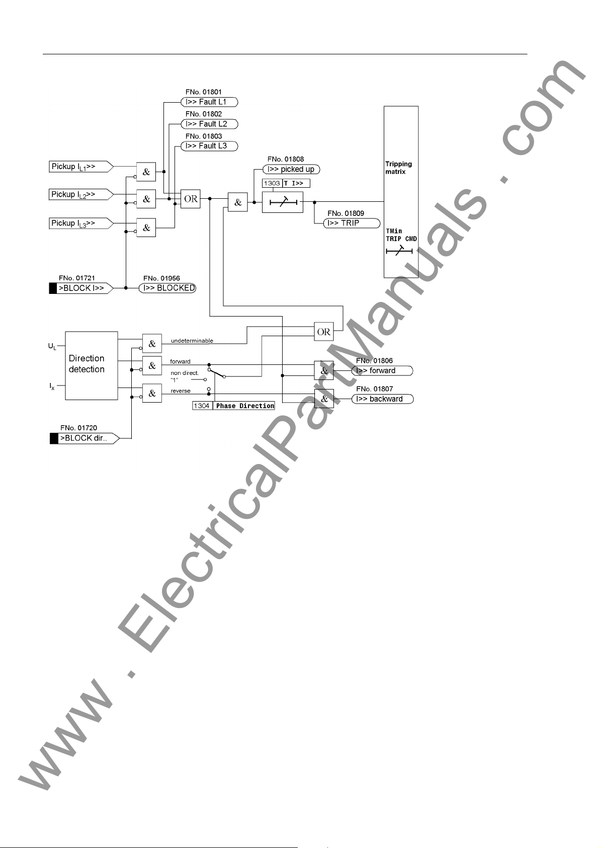
2 Functions
www . ElectricalPartManuals . com
Figure 2-7 Logic Diagram of I>> Stage with Direction Element
2.7.2 Setting Notes
General The high current stage I>> of the time overcurrent protection will only be effective and
available if address 113 O/C PROT. I>> is set to either directional or NonDirectional on configuration. If the function is not needed it is set to Disabled.
If direction acquisition is used, make sure that the CT and VT sets are consistent.
High-current Stage I>>
Address 1301 O/C I>> is used to switch the definite time I>> stage for phase currents
ON and OFF, or to block only the trip command (Block relay). The high-current
stage I>> (Parameter 1302 and its associated delay time T I>>, 1303) is used for
current grading with large impedances existing for example with transformers, motors
or generators. It is set in a way ensuring that it picks up for faults up to this impedance.
48
7UM61 Manual
C53000-G1176-C127-3
Page 49
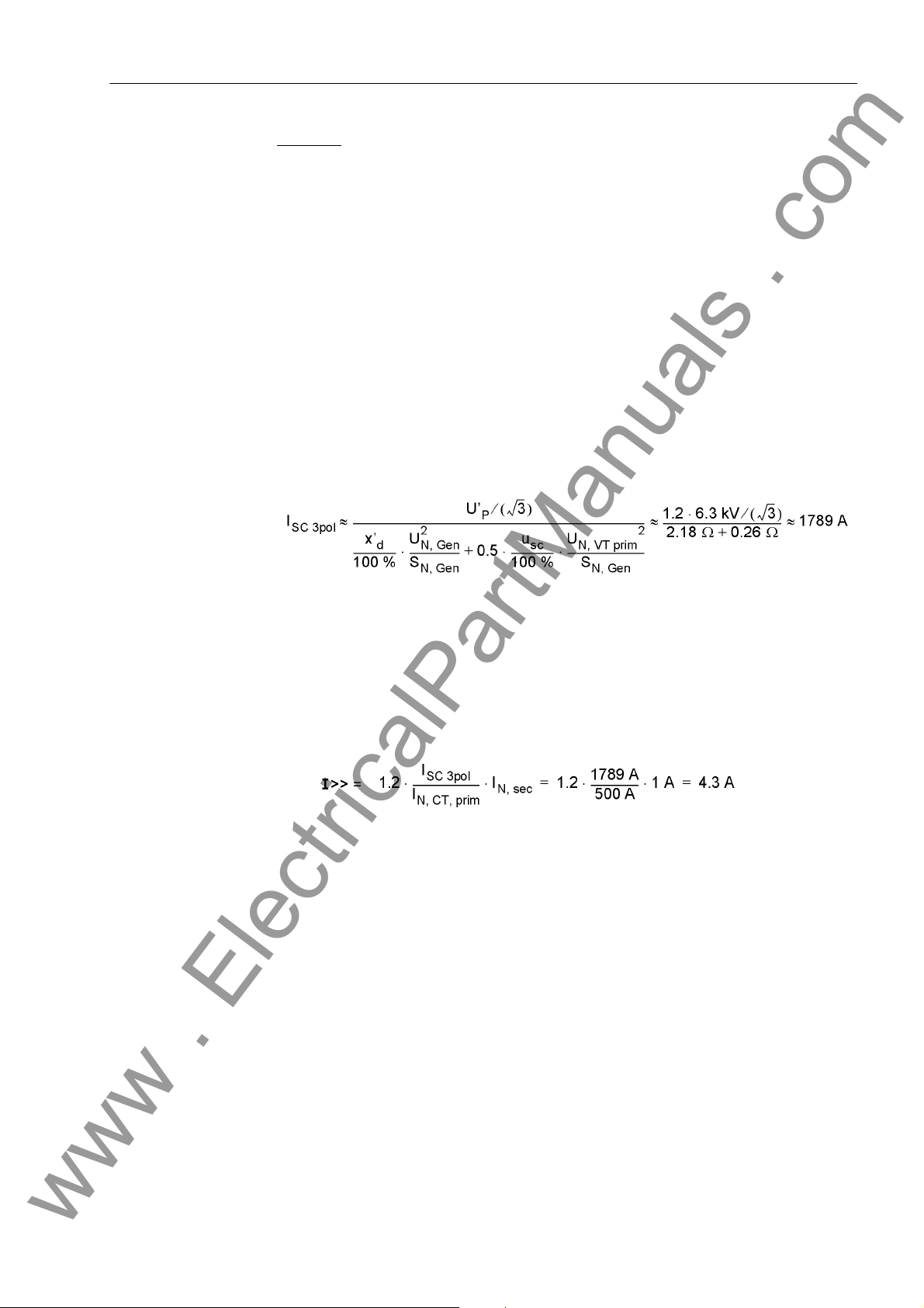
2.7 Definite-Time Overcurrent Protection (I>>, ANSI 50, 51, 67) with Direction Detection
www . ElectricalPartManuals . com
Current Transformer in the Starpoint
(without direction
detection)
Example: Unit Connection
Rated apparent power - generator S
Rated voltage - generator U
Direct-axis transient reactance x’
Transient synchronous generated voltage
(salient-pole generator)
Rated apparent power - transformer S
Rated voltage, on the generator side U
Transformer impedance u
Current transformer I
a) Short-circuit calculation
Three-pole short circuit
N, Mach
N, Mach
= 29 %
d
U’
= 1.2 · U
P
= 5.3 MVA
N, T
N, VT prim
= 7 %
sc
N, CT, prim
= 1 A
I
N, sec
= 5.27 MVA
= 6.3 kV
N,Mach
= 6.3 kV
= 500 A
Current Transformer on the Output
Side (with direction
detection)
b) Setting value:
The setting value is achieved by means of a conversion on the secondary side. In
order to exclude an unwanted operation caused by overvoltages or transient phenomena, an additional safety factor of about 1.2 to 1.3 is recommended.
A value of T I>> = 0.1 s is recommended as tripping time delay, in order to enable
preferred tripping of the differential protection.
If at Address 113 O/C PROT. I>> was configured as directional, the Addresses
1304 Phase Direction and 1305 LINE ANGLE are accessible. The inclination of
the direction straight line representing the separating line between the tripping and the
blocking zone can be adapted to the network conditions by way of the LINE ANGLE
parameter. To do this, the line angle of the network is set. The direction straight line is
perpendicular to the set direction angle. Together with the parameter 1304 Phase
Direction = Forward or Reverse, this parameter covers the entire impedance
level. This is the reverse direction, provided that the protective relay has been con-
nected correctly according to one of the diagrams in the Appendix. A small zone is
located between the forward and the reverse zone. Due to phase displacement angles
of the transformers, a proper direction decision is not possible. There is no tripping in
the configured preferential direction in this zone.
7UM61 Manual
C53000-G1176-C127-3
49
Page 50
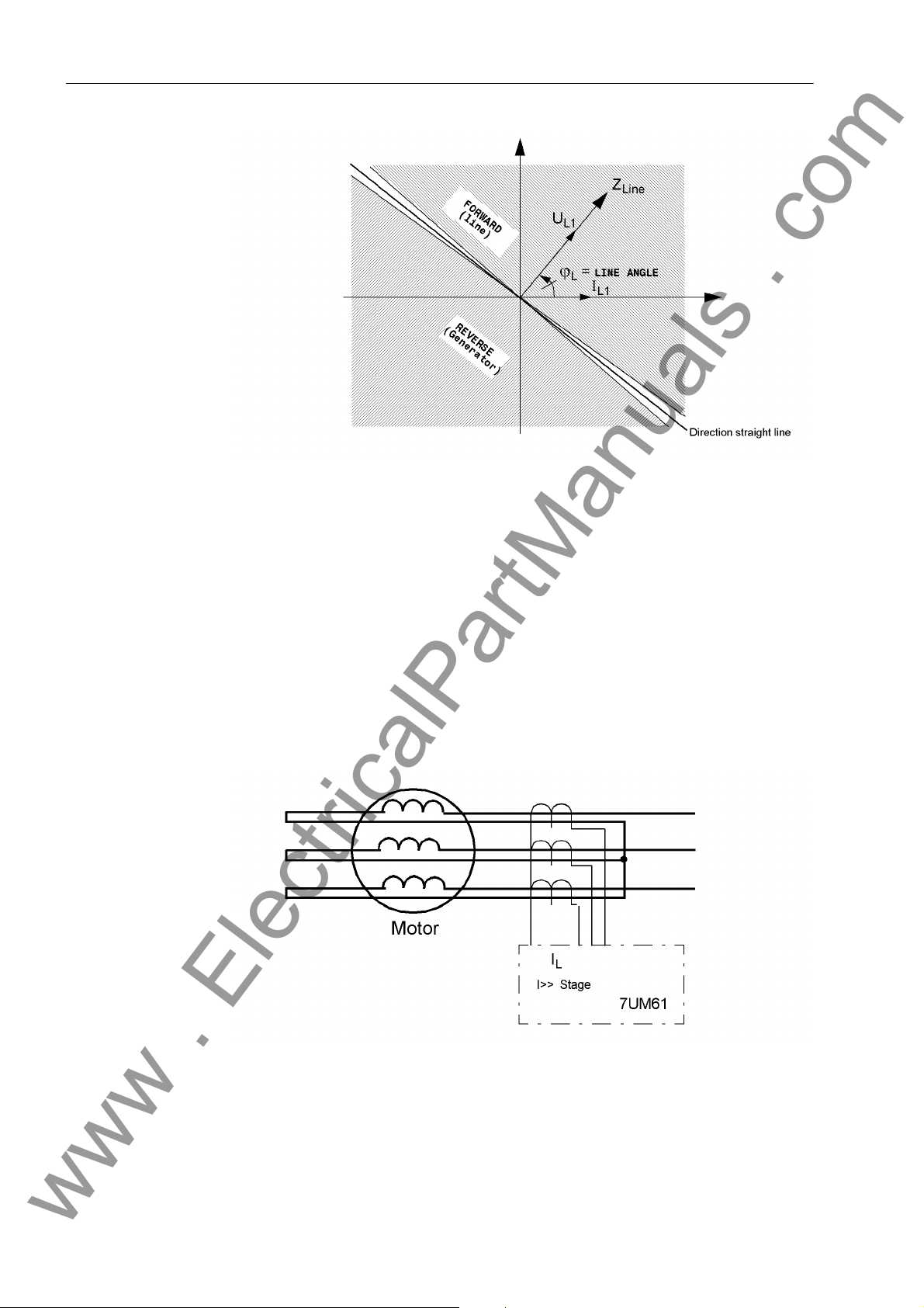
2 Functions
www . ElectricalPartManuals . com
Figure 2-8 Definition of Parameters 1304 Phase Direction and 1305 LINE ANGLE
Application Example: Motor Protection
The setting value of the direction straight line results from the short-circuit angle of the
feeding network. As a rule, it will be 60°. The current pickup value results from the
short-circuit current calculation. Workable pickup values are situated at about (1.5 to
2) · I
ancing procedures are finished.
For motors that have no no separate current transformer in the starpoint, the following
figure shows how to use the I>> stage as "differential protection". The configuration of
the protection function depends on the transformers. Since this application is most
likely to be used for replacements in an existing system, the settings of that system
should be the basis for this.
. A short tripping delay (TI>> ≈ 0.05 s to 0.1 s) is required to ensure that bal-
N, G
Figure 2-9 I>> Stage as "Differential Protection"
50
7UM61 Manual
C53000-G1176-C127-3
Page 51
2.7 Definite-Time Overcurrent Protection (I>>, ANSI 50, 51, 67) with Direction Detection
www . ElectricalPartManuals . com
2.7.3 Settings
The table indicates region-specific presettings. Column C (configuration) indicates the
corresponding secondary nominal current of the current transformer.
Addr. Parameter C Setting Options Default Setting Comments
1301 O/C I>> OFF
ON
Block relay
1302 I>> 1A 0.05 .. 20.00 A 4.30 A I>> Pickup
5A 0.25 .. 100.00 A 21.50 A
1303 T I>> 0.00 .. 60.00 sec; ∞ 0.10 sec T I>> Time Delay
1304 Phase Direction Forward
Reverse
1305 LINE ANGLE -90 .. 90 ° 60 ° Line Angle
OFF Overcurrent Time Protec-
tion I>>
Reverse Phase Direction
2.7.4 Information List
No. Information Type of In-
formation
1720 >BLOCK dir. EM >BLOCK direction I>> stage
1721 >BLOCK I>> EM >BLOCK I>>
1801 I>> Fault L1 AM O/C fault detection stage I>> phase L1
1802 I>> Fault L2 AM O/C fault detection stage I>> phase L2
1803 I>> Fault L3 AM O/C fault detection stage I>> phase L3
1806 I>> forward AM O/C I>> direction forward
1807 I>> backward AM O/C I>> direction backward
1808 I>> picked up AM O/C prot. I>> picked up
1809 I>> TRIP AM O/C I>> TRIP
1955 I>> OFF AM O/C prot. stage I>> is switched OFF
1956 I>> BLOCKED AM O/C prot. stage I>> is BLOCKED
1957 I>> ACTIVE AM O/C prot. stage I>> is ACTIVE
Comments
7UM61 Manual
C53000-G1176-C127-3
51
Page 52

2 Functions
www . ElectricalPartManuals . com
2.8 Inverse-Time Overcurrent Protection (ANSI 51V)
The overcurrent time protection replicates the short-circuit protection for small or lowvoltage machines. For larger machines it is used as back-up protection for the
machine short-circuit protection (differential protection and/or impedance protection).
It provides back-up protection for network faults which may be not promptly disconnected thus endangering the machine.
In generators where the excitation voltage is taken from the machine terminals, the
short-circuit current subsides quickly in the event of adjacent faults (i.e. in the generator or unit transformer region) due to the absence of excitation voltage. Within a few
seconds it sinks below the pick-up value of the overcurrent time protection. In order to
avoid a dropout of the pickup, the positive-sequence component is monitored additionally. This component can influence the overcurrent detection in accordance with two
different methods. Undervoltage influencing can be disabled.
The protective function operates, depending on the ordering variant, with an inverse
current-tripping characteristic according to the IEC or ANSI standards. The characteristics and associated formulas are given in the Technical Data. During configuration of
the inverse time curves, the independent stages I>> and I> are enabled (see Section
2.6).
2.8.1 Functional Description
Pickup and Tripping
Dropout The dropout of a picked up stage is performed as soon as the value falls below ap-
Undervoltage Consideration
Each phase current is compared individually with the common Ip setting value. If the
current exceeds 1.1 times the setting value, the stage picks up and is signaled phaserelated. For pickup the rms values of the fundamental harmonic are used. During the
pickup of an Ip stage, the tripping time is calculated from the flowing fault current using
an integrating measuring procedure, depending on the selected tripping characteristic. After the end of this period a trip command is transmitted.
proximately 95 % of the pickup value (i.e. 0.95 to 1.1 = 1.045 to setting value). A
renewed pickup will the delay timer to start anew.
The inverse overcurrent time protection is provided with a undervoltage detection that
can be disabled. This function can influence overcurrent detection in two different
ways:
• Voltage controlled: If the value falls below a settable voltage threshold, an over-
current stage with a lower pick-up value is enabled.
• voltage restraint: The pickup threshold of the overcurrent stage depends on the
voltage level. A lower voltage reduces the current pickup value (see the following
figure). A linear, directly proportional dependency is used in the zone between
U/U
= 1.00 and 0.25. Consequently, the following applies:
Nom
52
7UM61 Manual
C53000-G1176-C127-3
Page 53
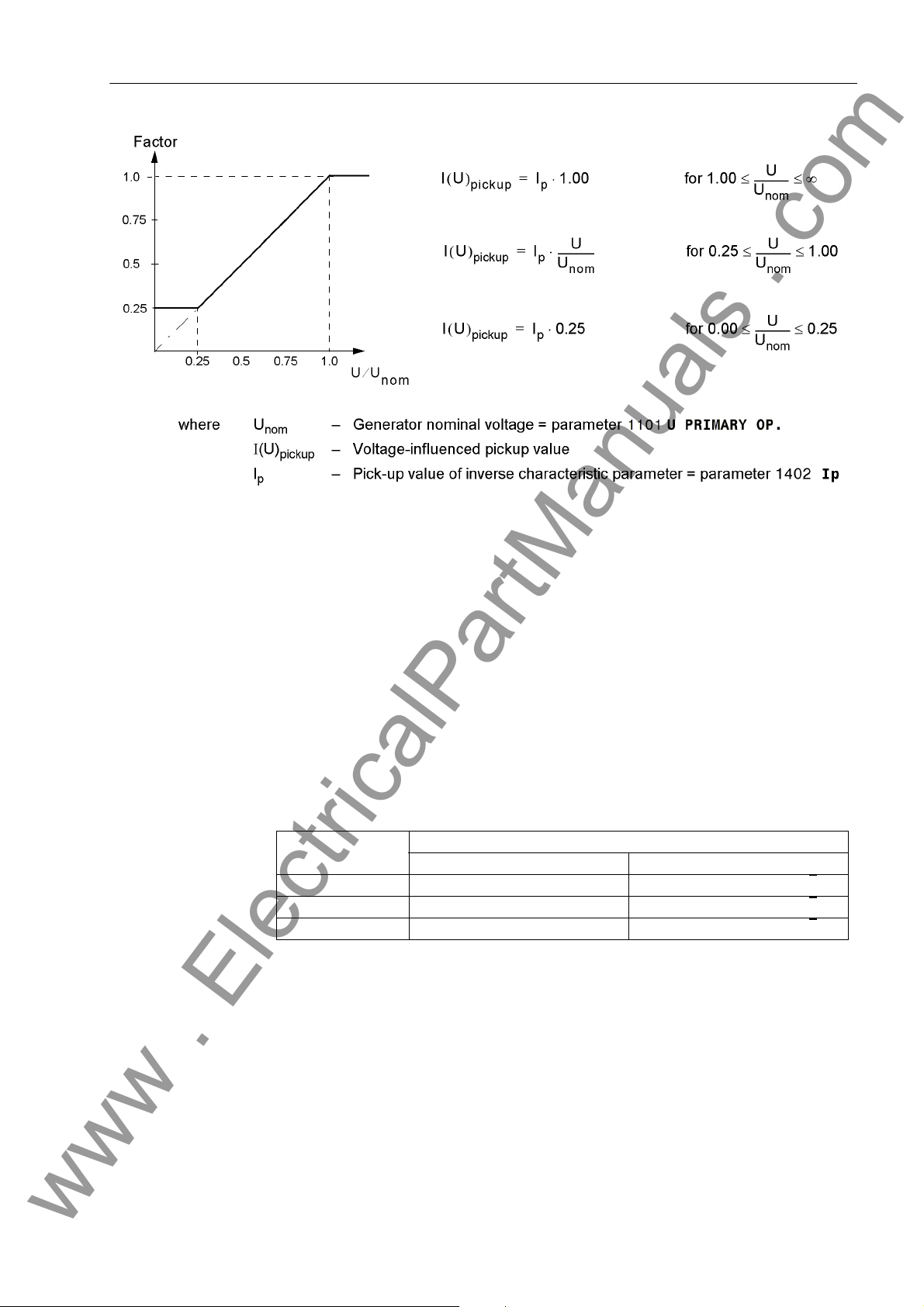
Figure 2-10 Pick-up Value Voltage Dependency
www . ElectricalPartManuals . com
2.8 Inverse-Time Overcurrent Protection (ANSI 51V)
The Ip reference value is decreased proportional to voltage decrease. Consequently
for constant current I, the I/Ip ratio is increased and the trip time is reduced. Compared
with the standard characteristics represented in Section 4 the tripping characteristic
shifts to the left side in relation to decreasing voltage.
The changeover to the lower pick-up value or the reduction of the pickup threshold are
performed on a per phase basis. Allocations of voltages to the current-carrying phases
represented in the following table apply. As the protection used in the generator range
is incorporated in the network grading plan, conversion of the voltages by the unit
transformer must also be considered. Therefore in principle a distinction must be
made between a unit connection and a busbar connection which must be communicated to the device by the parameter 272 SCHEME. As phase-to-phase voltages are
referred to in any case, faulty measurements during earth faults are avoided.
Table 2-3 Controlling voltages in relation to the fault currents
Current Voltage
Busbar connection Unit connection
I
L1
I
L2
I
L3
UL1 – U
UL2 – U
UL3 – U
L2
L3
L1
((UL1 – UL2) – (UL3 – U
((UL2 – UL3) – (UL1 – U
((UL3 – UL1) – (UL2 – U
)) / √3
L1
)) / √3
L2
)) / √3
L3
In or to avoid unwanted operation during a voltage transformer fault, a function blocking is implemented via a binary input controlled by the voltage transformer protective
breaker as well as via the device-internal measuring voltages failure detection (“Fuse–
Failure–Monitor”, also refer to Section 2.28).
The following figure shows the logic diagram of the inverse overcurrent time protection
without undervoltage influencing, whereas Figures 2-12 and 2-13 illustrate the logic diagrams with undervoltage influencing.
7UM61 Manual
C53000-G1176-C127-3
53
Page 54
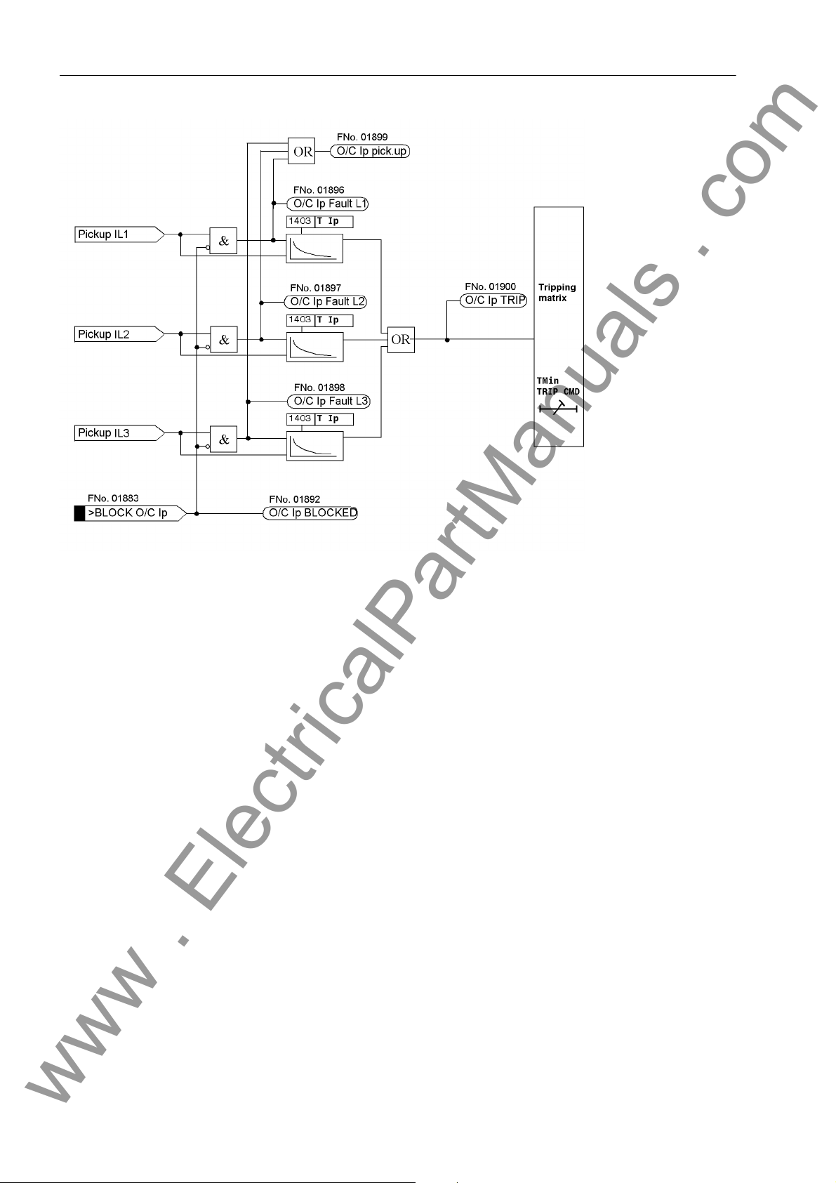
2 Functions
www . ElectricalPartManuals . com
Figure 2-11 Logic Diagram of the Inverse Overcurrent Time Protection without Undervoltage Influencing
54
7UM61 Manual
C53000-G1176-C127-3
Page 55
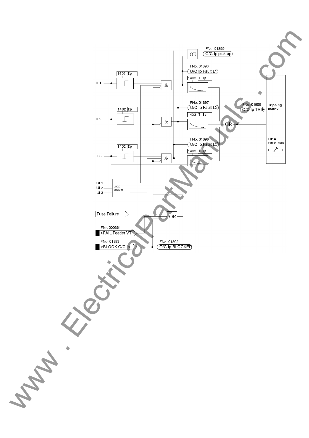
2.8 Inverse-Time Overcurrent Protection (ANSI 51V)
www . ElectricalPartManuals . com
Figure 2-12 Logic Diagram of the Voltage Controlled Inverse Overcurrent Time Protection
The changeover to the lower current pickup value on decreasing voltage (loop enable)
is performed on a phase by phase basis in accordance with Table 2-3.
7UM61 Manual
C53000-G1176-C127-3
55
Page 56
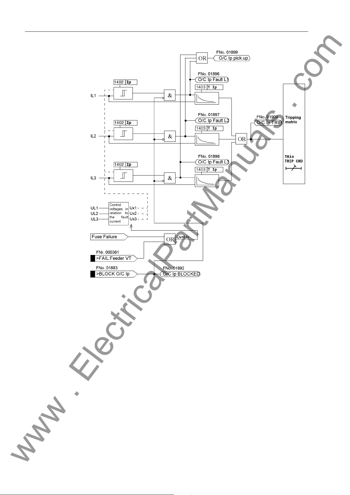
2 Functions
www . ElectricalPartManuals . com
Figure 2-13 Logic Diagram of the Voltage Restraint Inverse Time Overcurrent Protection
The reduction of the current pickup threshold on decreasing voltage (control voltage
allocation) is performed phase in accordance with Table 2-3.
2.8.2 Setting Notes
General Inverse overcurrent time protection is only effective and available if address 114 O/C
PROT. Ip was set to with IEC or with ANSI. If the function is not needed it is set
to Disabled.
Ip Overcurrent Stage
The address 1401 O/C Ip serves to switch the function ON or OFF or to block only
the trip command (Block relay). It must be noted that, for the inverse overcurrent
time protection, a safety factor of about 1.1 has been included between the pick-up
value and the setting value. This means that a pickup will only occur if a current of
about 1.1 times of the setting value is present. The dropout occurs as soon as the
value falls below 95% of the pickup value.
56
7UM61 Manual
C53000-G1176-C127-3
Page 57
2.8 Inverse-Time Overcurrent Protection (ANSI 51V)
www . ElectricalPartManuals . com
The current value is set at address 1402 Ip. The setting is mainly determined by the
maximum operating current. Pickup due to overload should never occur, since the
device in this operating mode operates as fault protection with correspondingly short
tripping times and not as overload protection.
The corresponding time multiplier for configuration of IEC characteristics (address
114 O/C PROT. Ip = with IEC) is accessible under address 1403 T Ip.
The corresponding time multiplier for configuration of ANSI characteristics (address
114 O/C PROT. Ip= with ANSI) is accessible under address 1404 TIME DIAL:
TD.
The time multipliers must be coordinated with the network grading plan.
The time multipliers can also be set to ∞. After pickup the element will then not trip.
Pickup, however, will be signaled. If the Ip stage is not required, on configuration of
the protection function (Section 2.2) address 114 O/C PROT. Ip is set to Disabled
or this function switched under 1401 O/C Ip = OFF.
The address 1408 serves to predefine the U< pick-up value for the undervoltage trip
of the Ip pickup value for voltage-controlled inverse overcurrent time protection/AMZ
(parameter 1407 VOLT. INFLUENCE = Volt. controll.). The parameter is set
to a value just below the lowest phase-to-phase voltage admissible during operation,
e.g. from 75 to 80 V. In this context, the same rules apply as for the undervoltage sealin of the definite overcurrent time protection (see also subsection 2.6.2).
If at address 1407 VOLT. INFLUENCE is set to without or Volt. restraint, the
parameter 1408 has no function.
2.8.3 Settings
The table indicates region-specific presettings. Column C (configuration) indicates the
corresponding secondary nominal current of the current transformer.
Addr. Parameter C Setting Options Default Setting Comments
1401 O/C Ip OFF
ON
Block relay
1402 Ip 1A 0.10 .. 4.00 A 1.00 A Ip Pickup
5A 0.50 .. 20.00 A 5.00 A
1403 T Ip 0.05 .. 3.20 sec; ∞ 0.50 sec T Ip Time Dial
1404 TIME DIAL: TD 0.50 .. 15.00 ; ∞ 5.00 TIME DIAL: TD
1405 IEC CURVE Normal Inverse
Very Inverse
Extremely Inv.
1406 ANSI CURVE Very Inverse
Inverse
Moderately Inv.
Extremely Inv.
Definite Inv.
OFF Inverse O/C Time Protec-
tion Ip
Normal Inverse IEC Curve
Very Inverse ANSI Curve
7UM61 Manual
C53000-G1176-C127-3
57
Page 58

2 Functions
www . ElectricalPartManuals . com
Addr. Parameter C Setting Options Default Setting Comments
1407 VOLT. INFLUENCE without
Volt. controll.
Volt. restraint
1408 U< 10.0 .. 125.0 V 75.0 V U< Threshold for Release
without Voltage Influence
Ip
2.8.4 Information List
No. Information Type of In-
formation
1883 >BLOCK O/C Ip EM >BLOCK inverse O/C time protection
1891 O/C Ip OFF AM O/C protection Ip is switched OFF
1892 O/C Ip BLOCKED AM O/C protection Ip is BLOCKED
1893 O/C Ip ACTIVE AM O/C protection Ip is ACTIVE
1896 O/C Ip Fault L1 AM O/C fault detection Ip phase L1
1897 O/C Ip Fault L2 AM O/C fault detection Ip phase L2
1898 O/C Ip Fault L3 AM O/C fault detection Ip phase L3
1899 O/C Ip pick.up AM O/C Ip picked up
1900 O/C Ip TRIP AM O/C Ip TRIP
Comments
58
7UM61 Manual
C53000-G1176-C127-3
Page 59

2.9 Thermal Overload Protection (ANSI 49)
www . ElectricalPartManuals . com
2.9 Thermal Overload Protection (ANSI 49)
The thermal overload protection prevents thermal overloading of the stator windings
of the machine being protected.
2.9.1 Functional Description
Thermal Profile The device calculates the excessive temperatures in accordance with a single-body
thermal model, based on the following differential equation:
with
Θ – Current overtemperature as a percent of final overtemperature at
Θ
the maximum admissible phase current k · I
K
– Coolant temperature as a difference to the 40 °C reference temper-
ature
N
τ – Thermal time constant for heatup of the equipment being protected
I – Current rms phase current as a percentage of maximum admissible
phase current I
The protection function models a thermal profile of the equipment being protected
(overload protection with memory capability). Both the previous history of an overload
and the heat loss to the environment are taken into account.
The solution of this equation is in steady-state operation an exponential function
whose asymptote represents the final temperature Θ
temperature threshold´is reached, an alarm is issued for e.g. load reduction measures. If the second overtemperature threshold, i.e. final overtemperature = trip temperature, is reached, the protected equipment is disconnected from the network. It is
also possible, however, to set the overload protection to Alarm Only . In this case
only an indication is issued when the final temperature is reached.
The overtemperature is calculated from the largest of the three phase currents. Since
the calculation is based on rms values of currents, harmonics which contribute to a
temperature rise of the stator winding are also considered.
The maximum thermally admissible continuous current I
of the nominal current I
I
= k · I
max
Apart from the k factor (parameter K-FACTOR) the TIME CONSTANT τ and the alarm
temperature Θ ALARM (as a percentage of the trip temperature Θ
tered.
N
:
N
max
= k · I
N
. After an initial settable over-
End
is described as a multiple
max
) are to be en-
TRIP
Overload protection also has a current alarm feature (I ALARM) in addition to the temperature alarm stage. This may report an overload current prematurely (before I
exceeded), even if the overtemperature has not yet attained the alarm or tripping
levels.
7UM61 Manual
C53000-G1176-C127-3
max
is
59
Page 60

2 Functions
www . ElectricalPartManuals . com
Coolant Temperature (Ambient Temperature)
C u r r e n t L i m i t i n g In order that overload protection on occurrence of high fault currents (and with small
With 7UM61 the thermal model of the considers an external temperature value. Depending on the application, this temperature can be the coolant or ambient temperature or, in the case of gas turbines, the entry temperature of the cold gas.
The temperature to be considered can be input in one of the following ways:
• via Profibus DP interface/Modbus
• Via temperature detection unit (Thermobox, RTD 1)
The ambient or coolant temperature can also be detected by an external temperature
sensor, digitized and fed to the 7UM61 via the Profibus-DP Interface / Modbus .
If a temperature supervision feature is implemented using a thermobox (see Section
2.32) the RTD1 input can be used for temperature inclusion in the overload protection.
With coolant temperature detection in accordance with one of the three methods described, the maximum permissible current I
ence of the coolant. If the ambient or coolant temperature is lower, the machine can
support a higher current than when the temperatures are high.
time constants) does not cause extremely short trip times thereby perhaps affecting
time grading of the fault protection, it is possible to implement current limiting for the
overload protection. Currents exceeding the value specified at parameter 1615 I MAX
THERM. are limited to this value. For this reason, they do not further reduce trip time
in the thermal memory.
is influenced by the temperature differ-
max
Standstill Time Constant
Blocking The thermal memory may be reset via a binary input (“>RM th.rep. O/L”). The
The above differential equation assumes a constant cooling that is reflected by the
time constant τ = R
tilated machine, however, the thermal time constant at standstill can differ considerably from the time constant of a continually running machine, since then the ventilation
provides for cooling whereas at standstill only natural convection takes place.
Therefore, two time constants must be considered in such cases for setting.
In this context, machine standstill is detected when the current undershoots the
threshold value BkrClosed I MIN (see margin heading "Current Flow Monitoring"
in Section 2.3).
current-induced excessive temperature value is reset to zero. The same is achieved
by entering a blocking (“>BLK ThOverload”); in that case the overload protection
is blocked completely, including the current alarm stage.
When machines must be started for emergency reasons, operating temperatures
above the maximum permissible overtemperatures can be allowed by blocking the
tripping signal via a binary input (“>Emer.Start O/L”). Since the thermal profile
may have exceeded the tripping temperature after startup and dropout of the binary
input has taken place, the protection function features a programmable run-on time interval (T EMERGENCY) which is started when the binary input drops out and continues
suppressing a trip signal. Tripping will be suppressed until this time interval elapses.
This binary input affects only the tripping signal. It has no effect on the fault condition
logging nor does it reset the thermal profile.
· Cth (thermal resistance and thermal capacitance). In a self-ven-
th
Behaviour in Case of Power Supply Failure
60
For overload protection, together with all other thermal protection functions of the
7UM61 in the Power System Data 1 (parameter 274 ATEX100, see Section 2.3) it is
possible to choose whether the calculated overtemperature will be stored throughout
a power supply failure, or reset to zero. This last option is the default setting.
7UM61 Manual
C53000-G1176-C127-3
Page 61

2.9 Thermal Overload Protection (ANSI 49)
www . ElectricalPartManuals . com
The following figure shows the logic diagram for overload protection.
Figure 2-14 Logic Diagram of the Overload Protection
7UM61 Manual
C53000-G1176-C127-3
61
Page 62

2 Functions
www . ElectricalPartManuals . com
2.9.2 Setting Notes
General Overload protection is only effective and accessible if address 116 Therm.Overload
is set to Enabled during configuration. If the function is not required Disabled is set.
Transformers and generators are prone to damage by extended overloads. These
overloads cannot and should not be detected by short-circuit protection. Time overcurrent protection should be set high so that it only detects faults, since short-circuit protection only permits short time delays. Short time delays, however, do not allow measures for unburdening the overloaded equipment nor do they permit advantage to be
taken of its (limited) overload capacity.
The 7UM61 protective relay features an overload protective function with thermal tripping characteristic adaptable to the overload capability of the equipment being protected.
At address 1601 Ther. OVER LOAD the thermal overload protection ON or OFF can
be set, the trip command blocked (Block relay) or the protection function set
toAlarm Only. In the latter case no fault record is created should an overload occur.
If overload protection is switched ON, tripping is also possible.
K Factor The overload protection is set with quantities per unit. The nominal current I
of the object to be protected (generator, motor, transformer) is typically used as base
current. The thermally admissible continuous current I
a factor k
The thermally admissible continuous current for the equipment being protected is generally obtainable from manufacturers specifications. If no specifications are available,
a value of 1.1 times the nominal current rating is assumed.
The K-FACTOR (address1602) to be set on the device 7UM61 refers to the secondary
nominal current (= device current). The following applies for the conversion:
prim
:
can be used to calculate
max prim
N, machine
with
I
I
I
62
Thermally admissible continuous motor primary current
max prim
N Machine
N CT prim
Nominal primary CT current
Nominal Current of the Machine
7UM61 Manual
C53000-G1176-C127-3
Page 63

2.9 Thermal Overload Protection (ANSI 49)
www . ElectricalPartManuals . com
Example: Generator and current transformer with the following data:
Permissible Continuous Current I
Generator Nominal Current I
Current Transformer 500 A / 1 A
Time Constant τ Overload protection tracks overtemperature progression, employing a thermal differ-
ential equation whose steady state solution is an exponential function. The TIME
CONSTANT τ (address 1603) is used in the calculation to determine the threshold of
excessive temperature and thus, the tripping temperature.
If the overload characteristic of the generator to be protected is pre-determined, the
user must select the protection trip characteristic so that it largely corresponds the
overload characteristic, at least for small overloads.
This is also the case if the admissible power-up time corresponding to a certain overload value is indicated.
Alarm Stages By setting the thermal alarm level Θ ALARM (address 1604), a alarm message can be
issued before the tripping temperature is reached, thus avoiding tripping by promptly
reducing load. This alarm level simultaneously represents the dropout level for the tripping signal. The tripping signal is interrupted only when this threshold value is again
undershot.
N Machine
max prim
= 483 A
= 1.15 · I
N, Machine
The thermal alarm level is given in % of the tripping overtemperature level.
Note: With the typical value of K-FACTOR = 1.1, on application of nominal machine
current and adapted primary transformer current, the following final tripping overtemperature results
of the tripping temperature. Consequently, the alarm stage should be set between the
final overtemperature with the nominal current (in this case 83 %) and the tripping
overtemperature (100 %).
In the present example, the thermal memory reaches the following value if the nominal
current is applied:
7UM61 Manual
C53000-G1176-C127-3
63
Page 64

2 Functions
www . ElectricalPartManuals . com
A current-related alarm level is also available (address 1610 I ALARM). The level is
set in secondary amperes and should be set equal to, or slightly less than, the permissible continuous current K-FACTOR · I
level by setting the thermal alarm level to 100 % and is then practically inactive.
. It may be used instead of the thermal alarm
N sec
Extension of Time Constants at Machine Standstill
Current Limiting The parameter 1615 I MAX THERM. specifies up to which current value the trip times
The time constant programmed at address 1603 is valid for the running machine. On
slowing down or standstill, the machine may cool down much more slowly. This be-
haviour can be modeled by prolonging the time constant by the Kτ-FACTOR (address
1612) on machine standstill. In this context, machine standstill is detected when the
current falls below the threshold value BkrClosed I MIN (see margin heading "Current Flow Monitoring" in section P.System Data 1).
If no distinction between time constants is necessary, the prolongation factor Kτ-
FACTOR can be left as 1.0 (default).
are calculated in accordance with the prescribed formula. In the trip characteristics of
the following figure, this limit value determines the transition to the horizontal part of
the characteristics, where there is no further trip time reduction for increasing current
values. The limit value must ensure that even for the highest possible short-circuit current, the trip times of the overload protection exceed the trip times of the short-circuit
protection devices (differential protection, impedance protection, time overcurrent protection). As a rule, a limitation to a secondary current corresponding to roughly three
times the nominal machine current will be sufficient.
64
7UM61 Manual
C53000-G1176-C127-3
Page 65
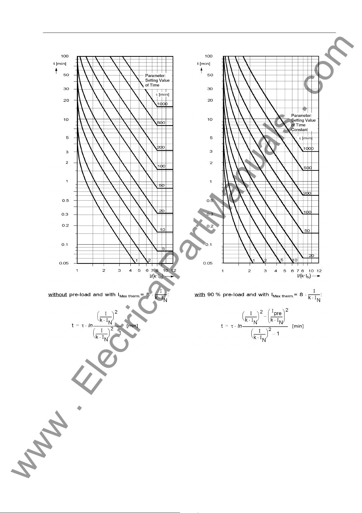
2.9 Thermal Overload Protection (ANSI 49)
www . ElectricalPartManuals . com
Figure 2-15 Tripping Characteristics for Overload Protection
Emergency Startup The run-on time to be entered at address 1616 T EMERGENCY must be sufficient to
ensure that after an emergency startup and dropout of binary input “>Emer.Start
O/L” the trip command is blocked until the thermal replica is again below the dropout
threshold.
Ambient or Coolant Temperature
7UM61 Manual
C53000-G1176-C127-3
The specifications given up to now are sufficient for modeling overtemperature. In addition to this, the machine protection can also process the ambient or coolant temperature. This temperature value must be communicated to the device as digitalized measured value via field bus (e.g. Profibus DP). Address 1607 TEMP. INPUT serves to
select the temperature input procedure. If there is no coolant temperature detection,
65
Page 66

2 Functions
www . ElectricalPartManuals . com
address 1607 is set to Disabled. The allocation between the input signal and the
temperature can be set at address 1608 (in °C) or 1609 (in °F) TEMP. SCAL.. For
this the temperature value set here corresponds to the 100% value from Profibus DP.
In the default setting, 100% (field bus) correspond to 100°C.
If under address 1607 TEMP. INPUT the temperature setting of RTD 1 selected, the
scaling under address1608 or 1609 is ineffective. The works setting can be left as it is.
If the ambient temperature detection is used, the user must be aware that the K-
FACTOR to be set refers to an ambient temperature of 104.00 °F or 40 °C, i.e. it corre-
sponds to the maximum permissible current at a temperature of 104.00 °F or 40 °C.
All calculations are performed with standardized quantities. The ambient temperature
must also be standardized. The temperature at nominal machine current is used as
standardization value. If the nominal machine current deviates from the nominal CT
current, the temperature must be adapted according to the following formula. At
address 1605 or 1606 TEMP. RISE I the temperature adapted to the nominal transformer current is set. This setting value is used as standardization quantity of the
ambient temperature input.
with
Machine Temperature with Secondary Nominal Current = Setting at
Θ
Nsec
Θ
Machine Temperature with Nominal Machine Current
NMach
I
Nominal primary CT current
Nprim
I
Nominal Current of the Machine
NMach
If the temperature input is not used, the address 1607 TEMP. INPUT is to be set to
Disabled . In this case, the settings of the addresses1605 or 1606 and 1608 or
1609 are not considered.
the 7UM61 (address 1605 or 1606)
66
7UM61 Manual
C53000-G1176-C127-3
Page 67
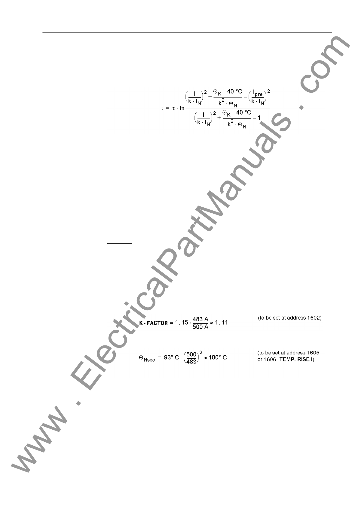
2.9 Thermal Overload Protection (ANSI 49)
www . ElectricalPartManuals . com
If the temperature input is used, the trip times change if the coolant temperature devi-
ates from the internal reference temperature of 104.00 °F or 40 °C. The following
formula can be used to calculate the trip time:
with
τ TIME CONSTANT (address 1603)
k K-FACTOR (address 1602)
I
N
I Actually Flowing Secondary Current
I
Pre
Θ
Temperature with Nominal Current IN(Address 1605)
N
Θ
Coolant Temperature Input (Scaling with Address 1608 or 1609)
K
Example:
Machine:
I
NMach
I
maxMach
τ
th
Current transformer: 500 A/1 A
Nominal Device Current
Previous Load Current
= 483 A
= 1.15 I
= 600 s (thermal time constant of the machine)
at ΘK = 40 °C
N
7UM61 Manual
C53000-G1176-C127-3
67
Page 68
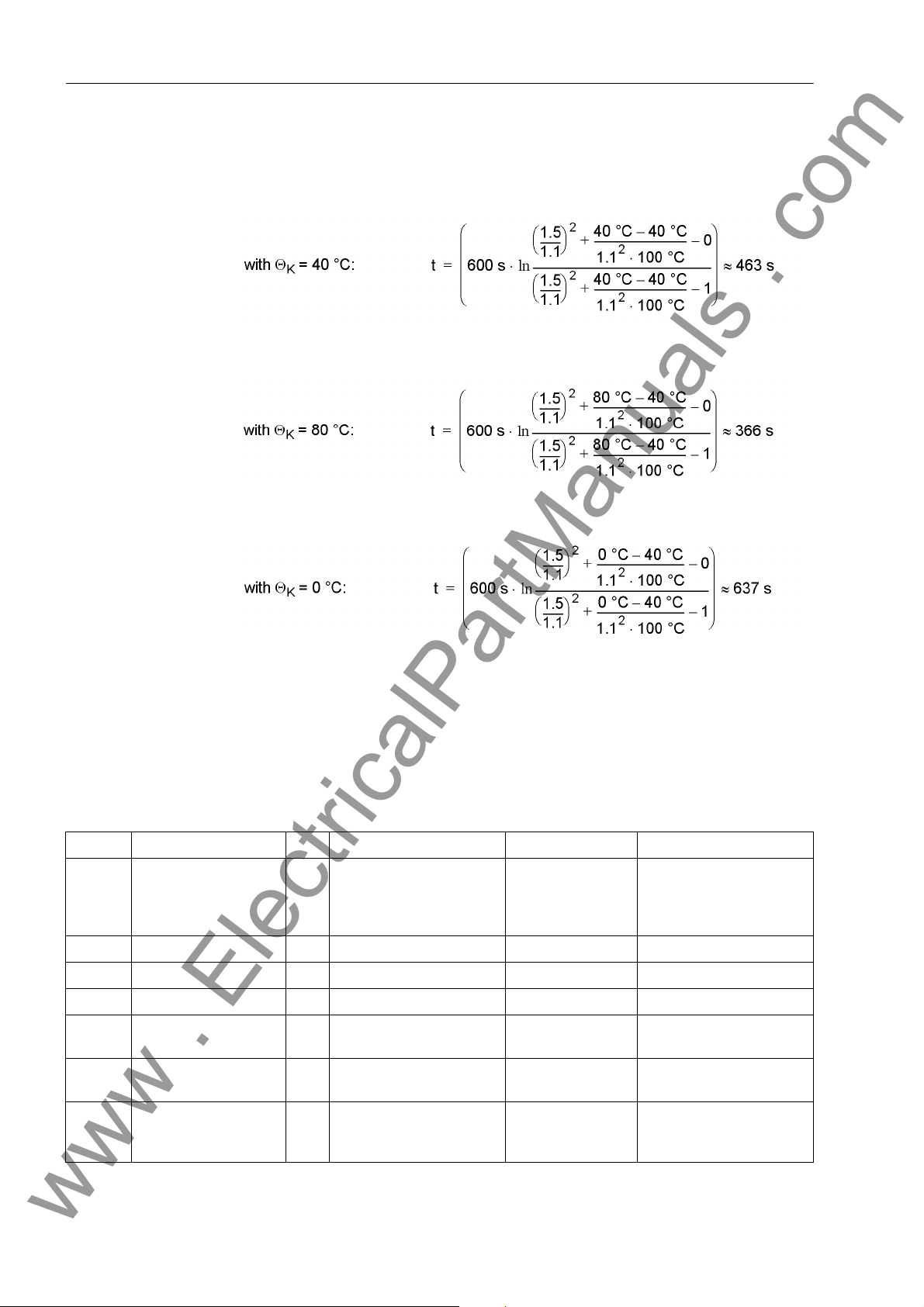
2 Functions
www . ElectricalPartManuals . com
With a supposed load current of I = 1.5 · I
ambient temperatures Θ
the following trip times result
K
N, Device
and a preload I
= 0, for different
pre
2.9.3 Settings
Addresses which have an appended "A" can only be changed with DIGSI, under Additional Settings.
The table indicates region-specific presettings. Column C (configuration) indicates the
corresponding secondary nominal current of the current transformer.
Addr. Parameter C Setting Options Default Setting Comments
1601 Ther. OVER LOAD OFF
ON
Block relay
Alarm Only
1602 K-FACTOR 0.10 .. 4.00 1.11 K-Factor
1603 TIME CONSTANT 30 .. 32000 sec 600 sec Thermal Time Constant
1604 Θ ALARM 70 .. 100 % 90 % Thermal Alarm Stage
1605 TEMP. RISE I 40 .. 200 °C100°C Temperature Rise at
1606 TEMP. RISE I 104 .. 392 °F212°F Temperature Rise at
1607 TEMP. INPUT Disabled
Fieldbus
RTD 1
OFF Thermal Overload Protec-
tion
Rated Sec. Curr.
Rated Sec. Curr.
Disabled Temperature Input
68
7UM61 Manual
C53000-G1176-C127-3
Page 69
2.9 Thermal Overload Protection (ANSI 49)
www . ElectricalPartManuals . com
Addr. Parameter C Setting Options Default Setting Comments
1608 TEMP. SCAL. 40 .. 300 °C100°C Temperature for Scaling
1609 TEMP. SCAL. 104 .. 572 °F212°F Temperature for Scaling
1610A I ALARM 1A 0.10 .. 4.00 A 1.00 A Current Overload Alarm
5A 0.50 .. 20.00 A 5.00 A
1612A Kτ-FACTOR 1.0 .. 10.0 1.0 Kt-Factor when Motor
1615A I MAX THERM. 1A 0.50 .. 8.00 A 3.30 A Maximum Current for
5A 2.50 .. 40.00 A 16.50 A
1616A T EMERGENCY 10 .. 15000 sec 100 sec Emergency Time
Setpoint
Stops
Thermal Replica
2.9.4 Information List
No. Information Type of In-
formation
1503 >BLK ThOverload EM >BLOCK thermal overload protection
1506 >RM th.rep. O/L EM >Reset memory for thermal replica O/L
1507 >Emer.Start O/L EM >Emergency start O/L
1508 >Fail.Temp.inp EM >Failure temperature input
1511 Th.Overload OFF AM Thermal Overload Protection OFF
1512 Th.Overload BLK AM Thermal Overload Protection BLOCKED
1513 Overload ACT AM Overload Protection ACTIVE
1514 Fail.Temp.inp AM Failure temperature input
1515 O/L I Alarm AM Overload Current Alarm (I alarm)
1516 O/L Θ Alarm AM Thermal Overload Alarm
1517 O/L Th. pick.up AM Thermal Overload picked up
1519 RM th.rep. O/L AM Reset memory for thermal replica O/L
1521 ThOverload TRIP AM Thermal Overload TRIP
Comments
7UM61 Manual
C53000-G1176-C127-3
69
Page 70
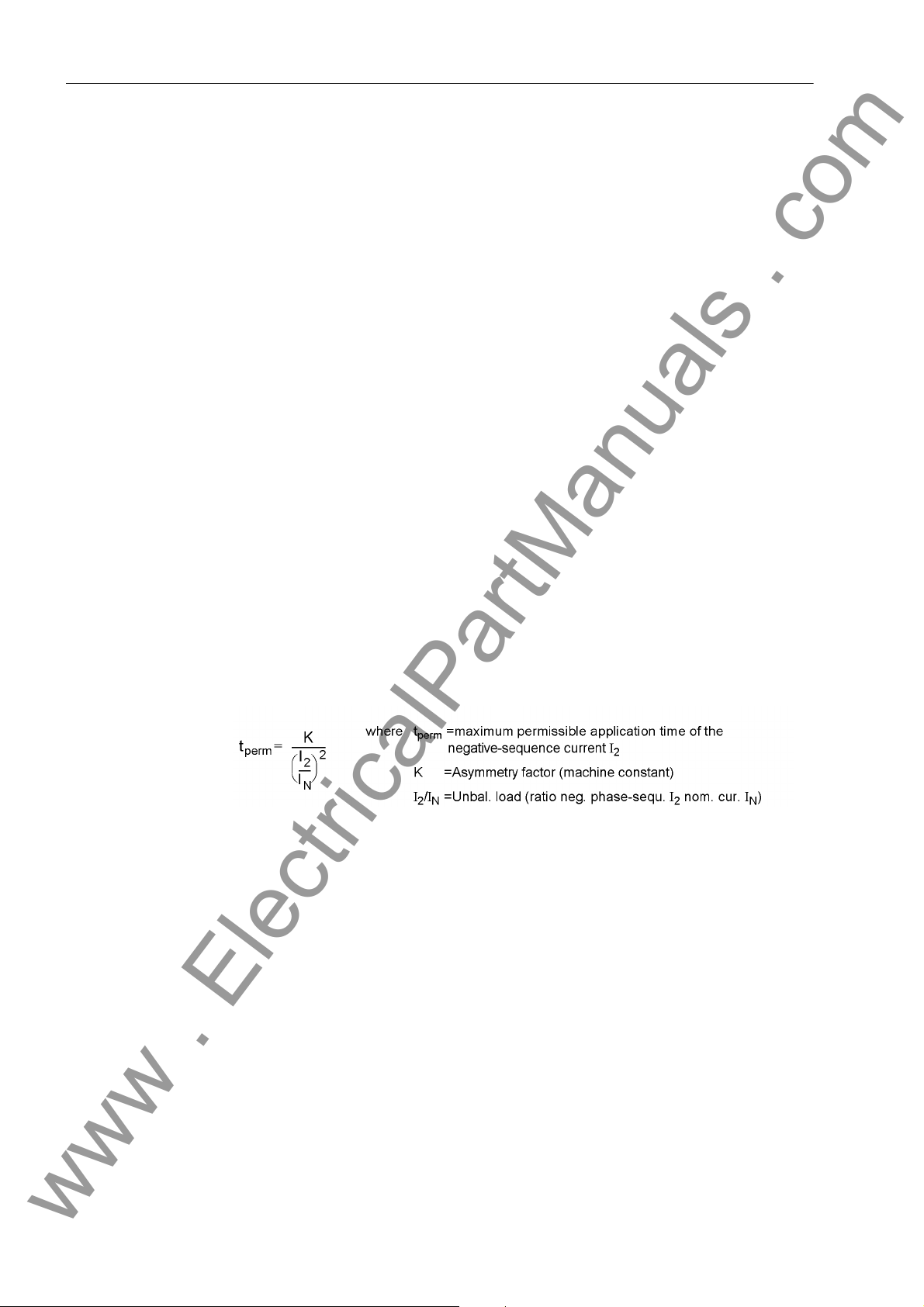
2 Functions
www . ElectricalPartManuals . com
2.10 Unbalanced Load (Negative Sequence) Protection (ANSI 46)
Unbalanced load protection detects unbalanced loads of three-phase induction machines. Unbalanced loads create a counter-rotating field which acts on the rotor at
double frequency. Eddy currents are induced at the rotor surface leading to local overheating in rotor end zones and slot wedges. Another effect of unbalanced loads is
overheating of the damper winding. In addition, this protection function may be used
to detect interruptions, short circuits and polarity problems with current transformers.
It is also useful in detecting 1-pole and 2-pole faults with magnitudes lower than the
load currents.
2.10.1 Functional Description
Unbalanced Load Determination
Warning Stage If the value of the continuously permissible, negative phase-sequence current I2> is
Thermal Characteristic
The unbalanced load protection of 7UM61 filters the fundamental component from the
phase currents and splits it into symmetrical components. It evaluates the negativephase sequence system, the negative phase-sequence current I
phase-sequence current exceeds a set threshold value, the trip timer starts. A trip
command is transmitted on timeout.
exceeded, after expiry of a set time T WARN a warning message “I2> Warn” is
issued (see Figure 2-16).
The machine manufacturers indicate the permissible unbalanced load by means of the
following formula:
The asymmetry factor depends on the machine and represents the time in seconds
during which the generator can be loaded with a 100 % unbalanced load. This factor
is typically in a range between 5 s and 30 s.
. If the negative
2
The heating up of the object to be protected is calculated in the device as soon as the
permissible unbalanced load I2> is exceeded. The current-time area is calculated
constantly to ensure correct consideration of different load cases. As soon as the
current-time-area ((I
teristic is tripped.
Limitation To avoid overfunctioning of the thermal tripping stage during asymmetrical short cir-
cuits, the input current I
of the I
ping time of the thermal function is constant. In addition the thermal memory is limited
to 200% of the tripping temperature. This avoids prolonged cooling after a delayed
short circuit tripping.
70
>> stage (Addr. 1701), whichever is smaller. Above this current value the trip-
2
)2 · t) has reached the K asymmetry factor, the thermal charac-
2/IN
is restricted. This limit is either 10 · I
2
or the setting value
2adm.
7UM61 Manual
C53000-G1176-C127-3
Page 71
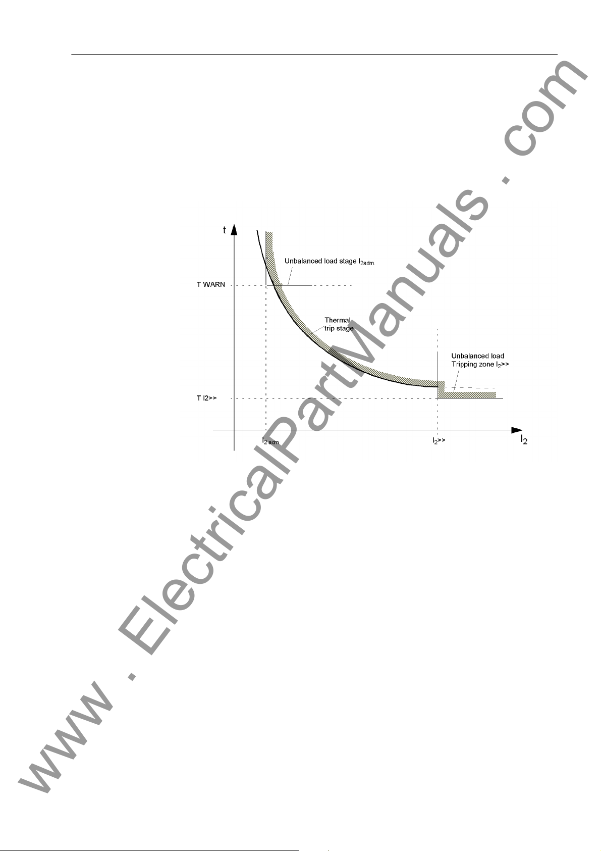
2.10 Unbalanced Load (Negative Sequence) Protection (ANSI 46)
www . ElectricalPartManuals . com
Cool Down A settable cool-down time starts as soon as the constantly permissible unbalanced
load I2> is undershot. The tripping drops out on dropout of the pickup threshold dropout. However, the counter content is reset to zero with the cooling time parameterized
at address 1705 T COOL DOWN. In this context, this parameter is defined as the time
required by the thermal image to cool down from 100 % to 0 %. The cool-down time
depends on the construction type of the generator, and especially on the damper winding. Preloading is taken into consideration when unbalanced loading occurs during the
cool-down period. The protective relay will thus trip in a shorter time.
Tripping Stages
Figure 2-16 Tripping Zone of the Unbalanced Load Protection
Definite Time Tripping Stage
Logic The following figure shows the logic diagram for the unbalanced load protection. The
High negative phase sequence currents can only be caused by a phase-to-phase
short circuit in the system which must be covered in accordance with the network
grading plan. For this reason, the thermal characteristic is cut by a selectable, definite
time negative phase-sequence current stage (parameters 1706 I2>> and 1707 T
I2>>).
Please also observe the instructions regarding phase sequence changeover in Sections 2.3 and 2.33.
protection may be blocked via a binary input (“>BLOCK I2”). Pickups and time
stages are reset and the metered values in the thermal model are cleared. The binary
input “>RM th.rep. I2” only serves to clear metered values of the thermal characteristic.
7UM61 Manual
C53000-G1176-C127-3
71
Page 72
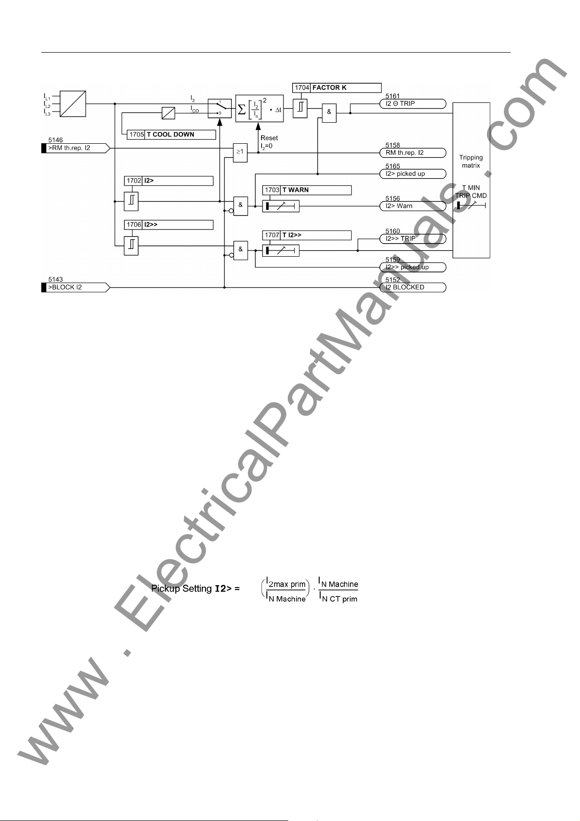
2 Functions
www . ElectricalPartManuals . com
Figure 2-17 Logic diagram of the unbalanced load protection
2.10.2 Setting Notes
General The unbalanced load protection is only in effect and accessible if address 117
UNBALANCE LOAD is set to Enabled during configuration. If the function is not re-
quired Disabled is set.
The address 1701 UNBALANCE LOAD serves to switch the unbalanced load protection ON or OFF or to block only the trip command (Block relay).
The maximum permissible, continual negative phase-sequence current is important
for the thermal model. For machines of up to 100 MVA with non-salient pole rotors, this
typically amounts to a value in a range from 6 % to 8 % of the nominal machine current,
and with salient-pole rotors at least 12 %. For larger machines and in cases of doubt,
please refer to the instructions of the machine manufacturer.
It is important to note that the manufacturer's data relate to the primary values of the
machine, for example, the maximum permissible continuous inverse current is referred to the nominal machine current. For settings on the protective relay, this data is
converted to the secondary inverse current. The following applies
with
Permissible thermal inverse current of the motor
Nominal current of the machine
Primary nominal current of the current transformer
7UM61 Manual
C53000-G1176-C127-3
72
I
2 perm prim
I
N Mach
I
N VT prim
Page 73
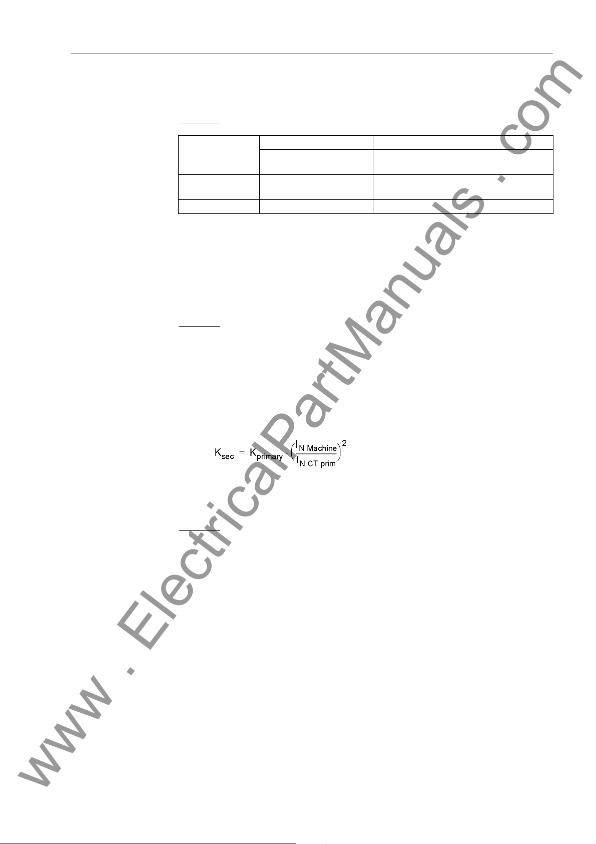
2.10 Unbalanced Load (Negative Sequence) Protection (ANSI 46)
www . ElectricalPartManuals . com
Pickup Threshold / Warning Stage
Negative Sequence Factor K
Conversion to Secondary Values
The value for I2> is set at Address 1702. It is at the same time the pickup value for a
current warning stage whose delay time T WARN is set at address 1703.
Example:
Machine I
Current transform-erI
Setting value I
N Mach
I
2 perm prim
N CT prim
2 adm.
/ I
N Mach
= 483 A
= 11 % permanent (salient-pole machine,
see Figure 2-18)
= 500 A
= 11 % · (483 A/500 A) = 10.6 %
If the machine manufacturer has indicated the loadability duration due to an unbalanced load by means of the constant K = (I
)2 · t, it is set directly at address1704
2/IN
FACTOR K. The constant K is proportional to the admissible energy loss.
The factor K can be derived from the unbalanced load characteristic according to the
following figure by reading the time at point I
= 1, corresponding to FACTOR K .
2/IN
Example:
t
= 20 s for I2/IN = 1
adm
The constant K
= 20 s determined in this way is valid for the machine side (pri-
primary
mary side).
The factor K
can be converted to the secondary side by means of the following
primary
formula:
The calculated asymmetry factor K
Example:
I
= 483 A
N Mach
I
N CT prim
Factor K
= 500 A
= 20 s
primary
Setting value at address 1704:
is set as FACTOR K at address 1704.
sec
7UM61 Manual
C53000-G1176-C127-3
73
Page 74

2 Functions
www . ElectricalPartManuals . com
Figure 2-18 Example of an Unbalanced Load Characteristic Specified by the Machine Man-
ufacturer
Cooldown Time The parameter 1705 T COOL DOWN establishes the time required by the protection
object to cool down under admissible unbalanced load I2> to the initial value. If the
machine manufacturer does not provide this information, the setting value can be calculated by assuming an equal value for cool-down time and heatup time of the object
to be protected. The formula below shows the relation between the K asymmetry
factor and the cool-down time:
Example:
The following cool-down time results for a K = 20 s and an admissible continual unbalanced load I
2/IN
= 11 %.
74
7UM61 Manual
C53000-G1176-C127-3
Page 75

2.10 Unbalanced Load (Negative Sequence) Protection (ANSI 46)
www . ElectricalPartManuals . com
This value T COOL DOWN is set at address 1705.
Definite-Time Tripping Characteristic
Asymmetrical faults also cause high negative phase-sequence currents. A definitetime negative phase-sequence current stage characteristic 1706 I2>> can thus
detect asymmetrical power system short circuits. A setting between 60 % and 65 %
ensures trip always occurs in accordance with the thermal characteristic in case of a
phase failure (unbalanced load continually below 100/√3
other hand, a two-pole short circuit can be assumed for an unbalanced load of more
between 60 % and 65 %. The delay time T I2>> (address 1707) must be coordinated
with the system grading of phase-to-phase short circuits.
Contrary to time-overcurrent protection, the I2>> stage is able to detect fault currents
at nominal current. The following conditions apply:
A phase-to-ground fault with current I corresponds to a negative sequence current:
A phase-to-ground fault with current I corresponds to a negative sequence current:
%, i.e. I2 < 58 %). On the
With an isolated starpoint, the I current value is particularly low and can be neglected.
With a low-resistance grounding, however, it is determined by the ground resistance.
2.10.3 Settings
Addr. Parameter Setting Options Default Setting Comments
1701 UNBALANCE LOAD OFF
ON
Block relay
1702 I2> 3.0 .. 30.0 % 10.6 % Continously Permissible Current
1703 T WARN 0.00 .. 60.00 sec; ∞ 20.00 sec Warning Stage Time Delay
1704 FACTOR K 2.0 .. 100.0 sec; ∞ 18.7 sec Negativ Sequence Factor K
1705 T COOL DOWN 0 .. 50000 sec 1650 sec Time for Cooling Down
7UM61 Manual
C53000-G1176-C127-3
OFF Unbalance Load Protection
I2
75
Page 76

2 Functions
www . ElectricalPartManuals . com
Addr. Parameter Setting Options Default Setting Comments
1706 I2>> 10 .. 100 % 60 % I2>> Pickup
1707 T I2>> 0.00 .. 60.00 sec; ∞ 3.00 sec T I2>> Time Delay
2.10.4 Information List
No. Information Type of In-
formation
5143 >BLOCK I2 EM >BLOCK I2 (Unbalance Load)
5146 >RM th.rep. I2 EM >Reset memory for thermal replica I2
5151 I2 OFF AM I2 switched OFF
5152 I2 BLOCKED AM I2 is BLOCKED
5153 I2 ACTIVE AM I2 is ACTIVE
5156 I2> Warn AM Unbalanced load: Current warning stage
5158 RM th.rep. I2 AM Reset memory of thermal replica I2
5159 I2>> picked up AM I2>> picked up
5160 I2>> TRIP AM Unbalanced load: TRIP of current stage
5161 I2 Θ TRIP AM Unbalanced load: TRIP of thermal stage
5165 I2> picked up AM I2> picked up
Comments
76
7UM61 Manual
C53000-G1176-C127-3
Page 77

2.11 Underexcitation (Loss-of-Field) Protection (ANSI 40)
www . ElectricalPartManuals . com
2.11 Underexcitation (Loss-of-Field) Protection (ANSI 40)
The underexcitation protection protects a synchronous machine from asynchronous
operation in the event of faulty excitation or regulation and from local overheating of
the rotor. Furthermore, it avoids endangering network stability by underexcitation of
large synchronous machines.
2.11.1 Function Description
Underexcitation Determination
Characteristic Curves
In order to detect underexcitation, the unit processes all three terminal phase currents
and all three terminal voltages to form the stator circuit criterion.
For the stator circuit criterion the admittance is calculated from the positive sequence
currents and voltages. The admittance measurement always produces the physically
appropriate stability limit, independently of voltage deviations from rated voltage.
Even in such circumstances the protection characteristic can be thus optimally
matched to the stability characteristic of the machine. By virtue of the positive sequence system evaluation, protection operates reliably even during asymmetrical
current or voltage conditions.
The following figure shows the loading diagram of the synchronous machine in the admittance plane (P/U
axis near 1/X
2
; –Q/U2) with the statistic stability limit which crosses the reactive
(reciprocal value of the synchronous direct reactance).
d
Figure 2-19 Admittance Diagram of Turbo Generators
7UM61 Manual
C53000-G1176-C127-3
77
Page 78

2 Functions
www . ElectricalPartManuals . com
The underexcitation protection in the 7UM61 makes available three independent,
freely combinable characteristics. As illustrated in the following figure, it is possible for
example to model static machine stability by means of two partial characteristics with
the same time delays (T CHAR. 1 = T CHAR 2). The partial characteristics are distinguished by the corresponding distance from the zero point (1/xd CHAR. 1) and (1/xd
CHAR. 2) as well as the corresponding inclination angle α
If the resulting characteristic (1/xd CHAR.1)/α
following figure on the left), a delayed warning (e.g. by 10 s) or a trip signal is transmitted. The delay is necessary to ensure that the voltage regulator is given enough
time to increase the excitation voltage.
; (1/xd CHAR.2)/α
1
and α
1
.
2
is exceeded (in the
2
Figure 2-20 Stator circuit criterion: Pick–Up Characteristic in Admittance Diagram
Excitation Voltage Query
Undervoltage Blocking
78
A further characteristic (1/xd CHAR.3 /α
characteristic of the synchronous machine. Since stable operation is impossible if this
characteristic is exceeded, immediate tripping is then required (time stage T CHAR 3).
With a faulty voltage regulator or excitation voltage failure, it is possible to switch off
with a short delay (time stage T SHRT Uex<, e.g. 1.5 s). For this purpose, excitation
voltage failure must be communicated to the device via a binary input.
The admittance calculation requires a minimum measurement voltage. During a
severe collapse (short-circuit) or failure of stator voltages, the protection is blocked by
an integrated AC voltage monitor whose pickup threshold 3014 Umin is set on delivery to 25 V. The parameter value is based on phase-to-phase voltages.
can be matched to the dynamic stability
3
7UM61 Manual
C53000-G1176-C127-3
Page 79

2.11 Underexcitation (Loss-of-Field) Protection (ANSI 40)
www . ElectricalPartManuals . com
The following figure shows the logic diagram for underexcitation protection.
Figure 2-21 Logic diagram of the Underexcitation Protection
2.11.2 Setting Notes
General The underexcitation protection is only effective and available if this function was set
during protective function configuration (Section 2.2, address 130, UNDEREXCIT. is
set to Enabled. If the function is not required Disabled is set. The address 3001
UNDEREXCIT. serves to enable the function ON and OFF or to block only the trip
command (Block relay).
The correct power system data input according to Section 2.3 is another prerequisite
for the parameterization of the underexcitation protection.
7UM61 Manual
C53000-G1176-C127-3
79
Page 80
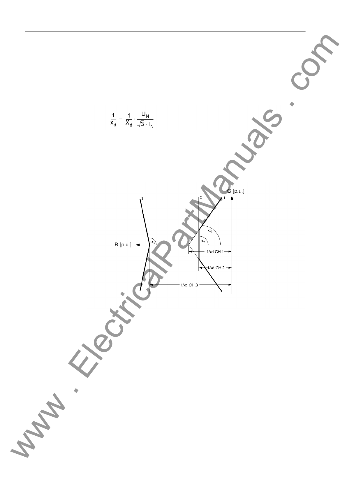
2 Functions
www . ElectricalPartManuals . com
The trip characteristics of the underexcitation protection in the admittance value
diagram are composed of straight segments which are respectively defined by their
admittance 1/xd (=coordinate distance) and their inclination angle α. The straight segments (1/xd CHAR.1)/α
form the static underexcitation limit (see the following figure). (1/xd CHAR.1) corresponds to the reciprocal value of the related synchronous direct reactance.
If the voltage regulator of the synchronous machine has underexcitation limiting, the
static characteristics are set in such a way that the underexcitation limiting of the
voltage regulator will intervene before characteristic 1 is reached (see figure 2-24).
(characteristic 1) and (1/xd CHAR.2)/α
1
(characteristic 2)
2
Characteristic Curve Values
80
Figure 2-22 Underexcitation Protection Characteristics in the Admittance Plane
If the generator capability diagram (see the following Figure) in its preferred representation (abscissa = positive reactive power; ordinate = positive active power) is transformed to the admittance plane (division by U
matched directly to the stability characteristic of the machine. If the axis sizes are
divided by the nominal apparent power, the generator diagram is indicated per unit
(this diagram corresponds to a per unit representation of the admittance diagram).
2
), the tripping characteristic can be
7UM61 Manual
C53000-G1176-C127-3
Page 81
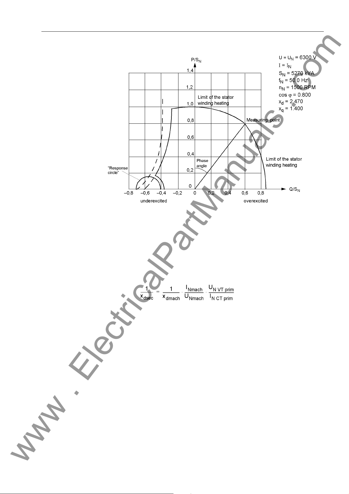
2.11 Underexcitation (Loss-of-Field) Protection (ANSI 40)
www . ElectricalPartManuals . com
Figure 2-23 Capability Curve of a Salient-Pole Generator, Indicated per Unit
The primary setting values can be read out directly from the diagram. The related
values must be converted for the protection setting. The same conversion formula can
be used if the protection setting is performed with the predefined synchronous direct
reactance.
with
related synchronous direct reactance, secondary,
x
dsec
x
related synchronous direct reactance of the machine,
d mach
I
Nominal Current of the Machine
NMach
U
Nominal Voltage of the Machine
NMach
U
N VT. prim
I
N CT prim
Instead of 1/x
current at no-load excitation).
Primary Nominal Voltage of the voltage transformers
Nominal primary CT current
the approximate value IK0/IN can be used (with IK0 = short-circuit
d mach
7UM61 Manual
C53000-G1176-C127-3
81
Page 82
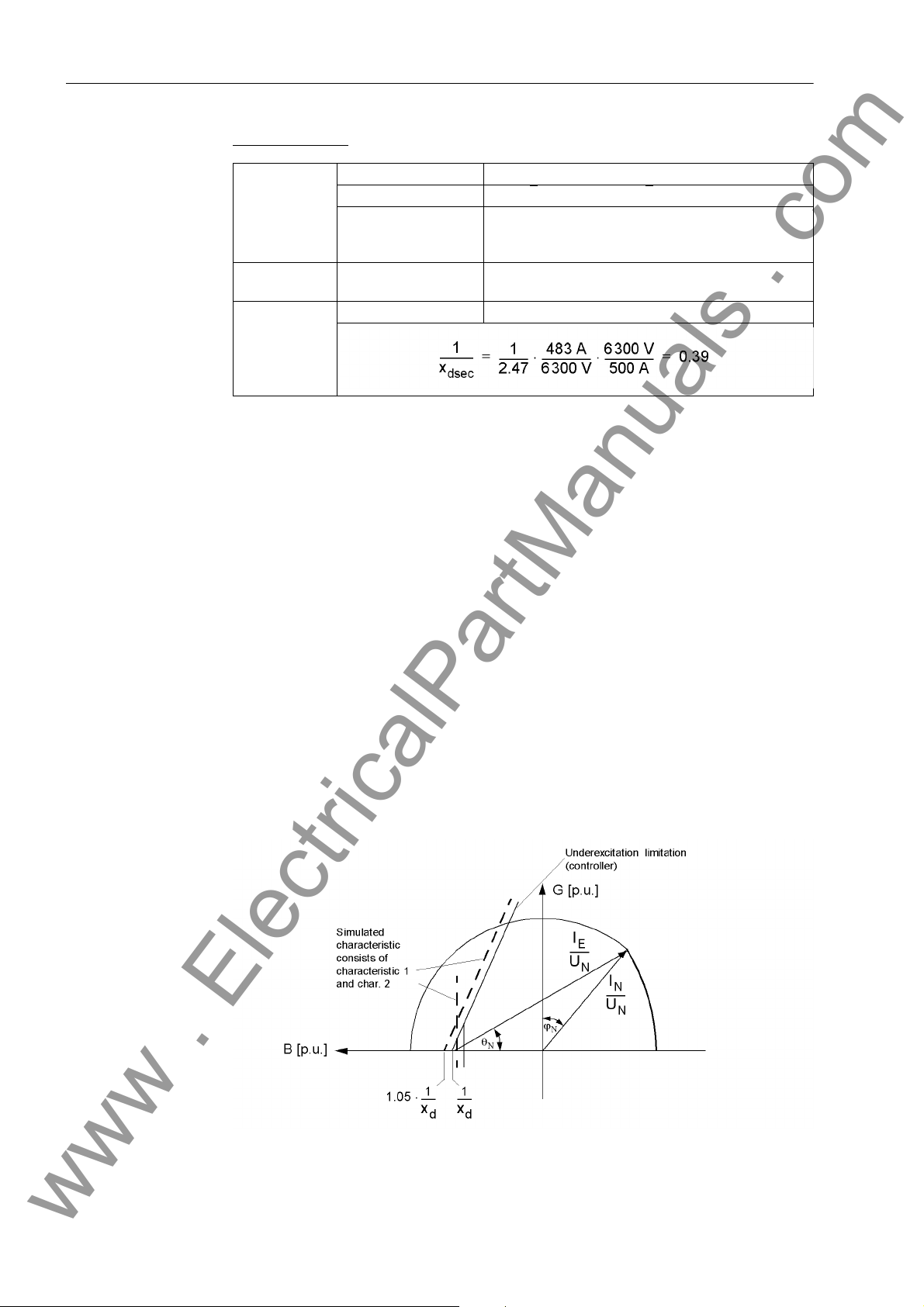
2 Functions
www . ElectricalPartManuals . com
Setting example:
Machine U
Current Transformer
Voltage transformer
Multiplied by a safety factor of about 1.05, the setting value 1/xd CHAR. 1 results
under address 3002.
For α1, the angle of the underexcitation limiting of the voltage regulator is selected or
the inclination angle of the machine stability characteristic is used. The setting value
ANGLE 1 is typically situated between 60 ° and 80 °.
In most cases, the machine manufacturer prescribes a minimum excitation value for
small active powers. For this purpose, characteristic 1 is cut from characteristic 2 for
low active-power load. Consequently, 1/xd CHAR. 2 is set to about 0.9· (1/xd
CHAR. 1), the ANGLE 2 to 90 °. The kinked tripping limit according to figure 2-22
(CHAR. 1, CHAR. 2) results in this way, if the corresponding time delays T CHAR. 1
and T CHAR. 2 of both characteristics are set equally.
N, Mach
I
N Machine
X
d mach
I
N CT prim
U
N VT. prim
= 6.3 kV
= SN/√3 UN = 5270 kVA/√3 · 6.3 kV = 483 A
= 2.47
(read from machine manufacturer's specifications in
Figure 2-23)
= 500 A
= 6.3 kV
Characteristic 3 serves to adapt the protection to the dynamic machine stability limits.
If there are no precise indications, the user must select a value 1/xd CHAR. 3, approximately between the synchronous direct reactance xd and the transient reactance
'. However, it should be greater than 1.
x
d
A value between 80 ° and 110 ° is usually selected for the corresponding ANGLE 3,
which ensures that only a dynamic instability can lead to a pickup with characteristic
3. The associated time delay is set at address 3010 T CHAR 3 to the value suggested
in Table 2-4.
Figure 2-24 Admittance diagram of a turbogenerator
82
7UM61 Manual
C53000-G1176-C127-3
Page 83
2.11 Underexcitation (Loss-of-Field) Protection (ANSI 40)
www . ElectricalPartManuals . com
Delay Times If the static limit curve consisting of the characteristics 1 and 2 is exceeded, the voltage
regulator must first have the opportunity of increasing the excitation. For this reason,
a warning message due to this criterion is ”long-time" delayed (at least 10 s for 3004
T CHAR. 1 and 3007 T CHAR. 2).
However if an external excitation monitoring signals the failure of an excitation voltage
to the device via a binary input, a switch-off can be performed with a short time delay.
Table 2-4 Setting the Underexcitation Protection
Characteristic 1 and 2 static stability undelayed Annunciation:
Exc < Anr
Characteristic 1 and 2 static stability long-time delayed
T CHAR. 1 = T CHAR. 2 ≈
10 s
Characteristic 1 and 2 Excitation
Voltage Failure
Characteristic 3 dynamic stability short–time delayed
Note: If very short time delays are selected, dynamic balancing procedures may
cause unwanted operations. For this reason, it is recommended to set time values of
0.05 s or higher.
short–time delayed
T SHRT Uex< ≈ 1.5 s
T CHAR 3 ≈ 0.5 s
Trippings
Err<1 TRIP / Err<2 TRIP
Tripping
Err< UPU < TRIP
Tripping
Exc<3 TRIP
2.11.3 Settings
Addresses which have an appended "A" can only be changed with DIGSI, under Additional Settings.
Addr. Parameter Setting Options Default Setting Comments
3001 UNDEREXCIT. OFF
ON
Block relay
3002 1/xd CHAR. 1 0.25 .. 3.00 0.41 Conductance Intersect Character-
3003 ANGLE 1 50 .. 120 ° 80 ° Inclination Angle of Characteristic
3004 T CHAR. 1 0.00 .. 60.00 sec; ∞ 10.00 sec Characteristic 1 Time Delay
3005 1/xd CHAR. 2 0.25 .. 3.00 0.36 Conductance Intersect Character-
3006 ANGLE 2 50 .. 120 ° 90 ° Inclination Angle of Characteristic
3007 T CHAR. 2 0.00 .. 60.00 sec; ∞ 10.00 sec Characteristic 2 Time Delay
3008 1/xd CHAR. 3 0.25 .. 3.00 1.10 Conductance Intersect Character-
3009 ANGLE 3 50 .. 120 ° 90 ° Inclination Angle of Characteristic
OFF Underexcitation Protection
istic 1
1
istic 2
2
istic 3
3
3010 T CHAR 3 0.00 .. 60.00 sec; ∞ 0.30 sec Characteristic 3 Time Delay
7UM61 Manual
C53000-G1176-C127-3
83
Page 84
2 Functions
www . ElectricalPartManuals . com
Addr. Parameter Setting Options Default Setting Comments
3011 T SHRT Uex< 0.00 .. 60.00 sec; ∞ 0.50 sec T-Short Time Delay (Char. &
Uexc<)
3014A Umin 10.0 .. 125.0 V 25.0 V Undervoltage blocking Pickup
2.11.4 Information List
No. Information Type of In-
formation
5323 >Exc. BLOCK EM >BLOCK underexcitation protection
5327 >Char. 3 BLK. EM >BLOCK underexc. prot. char. 3
5328 >Uexc fail. EM >Exc. voltage failure recognized
5329 >Char. 1 BLK. EM >BLOCK underexc. prot. char. 1
5330 >Char. 2 BLK. EM >BLOCK underexc. prot. char. 2
5331 Excit. OFF AM Underexc. prot. is switched OFF
5332 Excit.BLOCKED AM Underexc. prot. is BLOCKED
5333 Excit.ACTIVE AM Underexc. prot. is ACTIVE
5334 Exc. U< blk AM Underexc. prot. blocked by U<
5336 Uexc failure AM Exc. voltage failure recognized
5337 Exc< picked up AM Underexc. prot. picked up
5343 Exc<3 TRIP AM Underexc. prot. char. 3 TRIP
5344 Exc<1 TRIP AM Underexc. prot. char. 1 TRIP
5345 Exc<2 TRIP AM Underexc. prot. char. 2 TRIP
5346 Exc<U<TRIP AM Underexc. prot. char.+Uexc< TRIP
Comments
84
7UM61 Manual
C53000-G1176-C127-3
Page 85

2.12 Reverse Power Protection (ANSI 32R)
www . ElectricalPartManuals . com
Reverse power protection is used to protect a turbo-generator unit on failure of energy
to the prime mover when the synchronous generator runs as a motor and drives the
turbine taking motoring energy from the network. This condition leads to overheating
of the turbine blades and must be interrupted within a short time by tripping the
network circuit-breaker. For the generator there is the additional risk that with a malfunctioning residual steam pass (defective stop valves) after the switching off of the
circuit breaker the turbine generator unit is accelerated to overspeed. For this reason,
the system isolation should only be performed after the detection of active power input
into the machine.
2.12.1 Function Description
2.12 Reverse Power Protection (ANSI 32R)
Reverse Power Determination
Pickup Seal-In Time To ensure that frequently occurring short pickups can cause tripping, it is possible to
Trip Signal For bridging a perhaps short power input during synchronisation or during power
The reverse power protection of the 7UM61 precisely calculates the active power from
the symmetrical components of the fundamental waves of voltages and currents by
averaging the values of the last 16 cycles. The evaluation of only the positive phasesequence systems makes the reverse power determination independent of current
and voltage asymmetries and corresponds to actual loading of the drive end. The calculated active power value corresponds to the overall active power. By taking the error
angles of the instrument transformers into account, the active power component is
exactly calculated even with very high apparent powers and low power factor (cos ϕ).
The correction is performed by a W0 constant correction angle determined during
commissioning of the protection device in the system. The correction angle is set
under Power System Data 1 (see Section 2.3).
perform a selectable prolongation of these pickup pulses at parameter 3105 T-HOLD.
Each positive edge of the pickup pulses triggers this time stage again. For a sufficient
number of pulses, the pickup signals adds up and become longer than the time delay.
swings caused by system faults, the trip command is delayed by a selectable time T-
SV-OPEN . In case of a closed emergency tripping valve, a short delay is, however,
sufficient. By means of entering the emergency tripping valve position via a binary
input, the short time delay T-SV-CLOSED becomes effective under an emergency tripping condition. The time T-SV-OPEN is still effective as back-up stage.
It is also possible to block tripping via an external signal.
The following figure shows the logic diagram for the reverse power protection.
7UM61 Manual
C53000-G1176-C127-3
85
Page 86
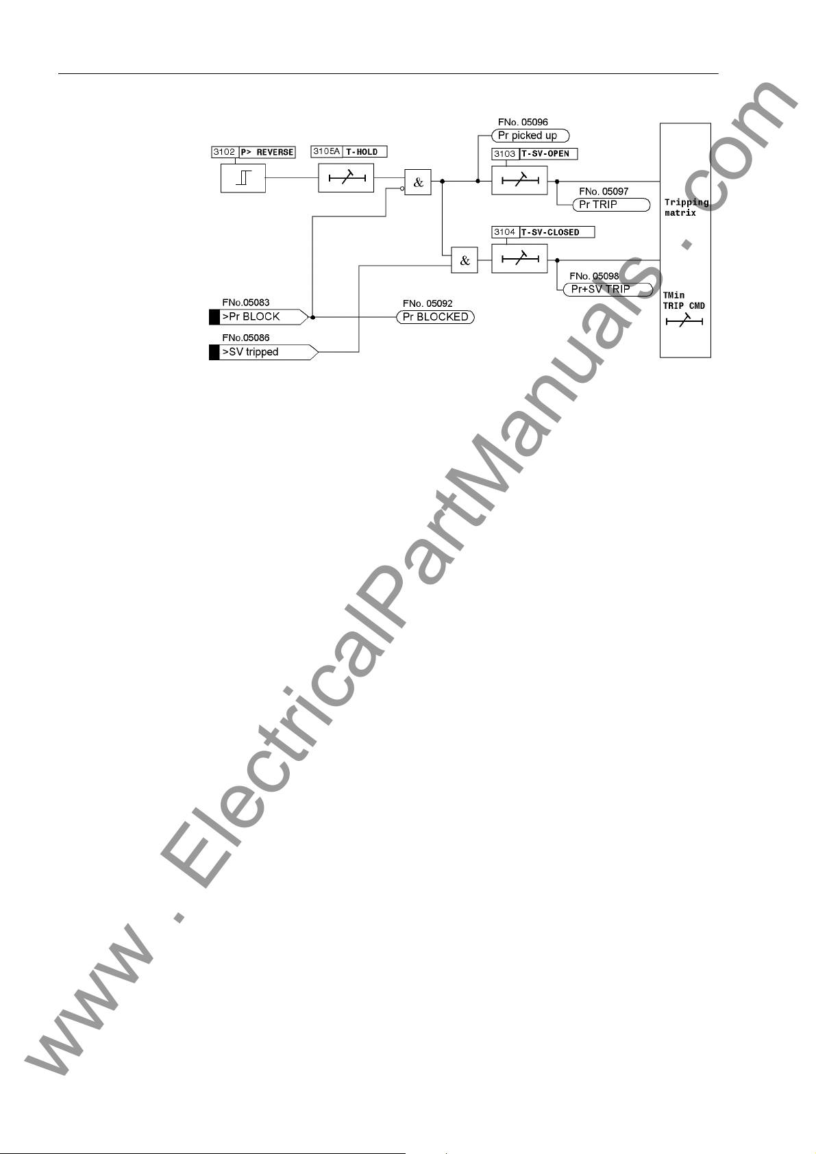
2 Functions
www . ElectricalPartManuals . com
Figure 2-25 Logic Diagram of the Reverse Power Protection
2.12.2 Setting Notes
General Reverse power protection is only effective and available if this function was set during
protective function configuration (Section 2.2, address 131, REVERSE POWER is set
to Enabled. If the function is not required Disabled is set. The address 3101
REVERSE POWER serves to switch the function ON or OFF or to block only the trip
command (Block relay).
In case of a reverse power, the turbine set must be disconnected from the system as
the turbine operation is not permissible without a certain minimum steam throughput
(cooling effect) or, in case of a gas turbine set, the motor load would be too heavy for
the network.
Pickup Values The level of the active power input is determined by the friction losses to be overcome
and is in the following ranges, depending on the individual system:
• Steam turbines: P
• Gas turbines: P
• Diesel drives: P
For the primary test, the reverse power should be measured with the relay. The user
should select a setting of 0.5 times the value of the measured motoring energy. This
value can be found under the percentage operational measured values. The feature
of correcting angle faults of the current and voltage transformers should be used especially in case of very large machines with a particularly low motoring energy (see
sections 2.3).
Reverse/SN
Reverse/SN
Reverse/SN
≈ 1 % to 3 %
≈ 3 % to 5 %
> 5 %
86
7UM61 Manual
C53000-G1176-C127-3
Page 87

2.12 Reverse Power Protection (ANSI 32R)
www . ElectricalPartManuals . com
The pickup value 3102 P> REVERSE is set in percent of the secondary apparent
· U
· I
power rating SNsec = √3
be converted to secondary quantities using the following formula:
with
Psec Secondary power corresponding to setting value
Nsec
. If the primary motoring energy is known, it must
Nsec
Secondary rated power = √3 · U
S
Nsec
P
Machine power corresponding to setting value
Mach
S
U
I
U
I
Pickup Seal-In Time The 3105 T-HOLD pickup seal-in time serves to extend pulsed pickups to the param-
eterized minimum duration.
Delay Times If reverse power without emergency tripping is used, a corresponding time delay must
be implemented to bridge any short reverse power states after synchronization or
power swings subsequent to system faults (e.g. 3-pole short circuit). Usually, a delay
time 3103 T-SV-OPEN = approx. 10 s is set.
Under emergency tripping conditions, the reverse power protection performs a shorttime delayed trip subsequent to the emergency tripping via an oil-pressure switch or a
position switch at the emergency trip valve. Before tripping, it must be ensured that the
reverse power is only caused by the missing drive power at the turbine side. A time
delay is necessary to bridge the active power swing in case of sudden valve closing,
until a steady state active power value is achieved. A 3104 T-SV-CLOSED time delay
of about 1 to 3 s is sufficient for this purpose, whereas a time delay of about 0.5 s is
recommended for gas turbine sets. The set times are additional time delays not including the operating times (measuring time, drop-out time) of the protective function.
Nominal apparent power of the machine
N, Mach
Nominal Voltage of the Machine
N, Mach
Nominal Current of the Machine
N Mach
Primary Nominal Voltage of the voltage transformers
N prim
Nominal primary CT current
N prim
Nsec
· I
Nsec
7UM61 Manual
C53000-G1176-C127-3
87
Page 88
2 Functions
www . ElectricalPartManuals . com
2.12.3 Settings
Addresses which have an appended "A" can only be changed with DIGSI, under Additional Settings.
Addr. Parameter Setting Options Default Setting Comments
3101 REVERSE POWER OFF
ON
Block relay
3102 P> REVERSE -30.00 .. -0.50 % -1.93 % P> Reverse Pickup
3103 T-SV-OPEN 0.00 .. 60.00 sec; ∞ 10.00 sec Time Delay Long (without Stop
3104 T-SV-CLOSED 0.00 .. 60.00 sec; ∞ 1.00 sec Time Delay Short (with Stop
3105A T-HOLD 0.00 .. 60.00 sec; ∞ 0.00 sec Pickup Holding Time
OFF Reverse Power Protection
Val ve)
Val ve)
2.12.4 Information List
No. Information Type of In-
formation
5083 >Pr BLOCK EM >BLOCK reverse power protection
5086 >SV tripped EM >Stop valve tripped
5091 Pr OFF AM Reverse power prot. is switched OFF
5092 Pr BLOCKED AM Reverse power protection is BLOCKED
5093 Pr ACTIVE AM Reverse power protection is ACTIVE
5096 Pr picked up AM Reverse power: picked up
5097 Pr TRIP AM Reverse power: TRIP
5098 Pr+SV TRIP AM Reverse power: TRIP with stop valve
Comments
88
7UM61 Manual
C53000-G1176-C127-3
Page 89
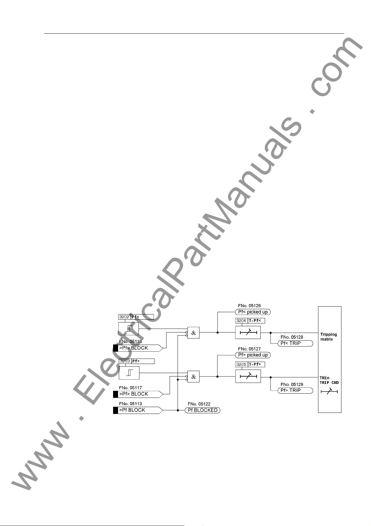
2.13 Forward Active Power Supervision (ANSI 32F)
www . ElectricalPartManuals . com
2.13 Forward Active Power Supervision (ANSI 32F)
The machine protection 7UM61 includes an active power supervision which monitors
whether the active power undershoots one set value or overshoots a separate second
set value. Each of these functions can initiate different control functions.
When, for example, with generators operating in parallel, the active power output of
one machine becomes so small that other generators could take over this power, then
it is often appropriate to shut down the lightly loaded machine. The criterion in this
case is that the "forwards" power supplied into the network falls below a certain value.
In many applications it can be desirable to issue a control signal if the active power
output rises above a certain value.
When a fault in a utility network is not cleared within a critical time, the utility network
and should be split or for example, an industrial network decoupled from it. As criteria
for decoupling, in addition to power flow direction, are undervoltage, overcurrent and
frequency. As a result, the 7UM61 can also be used for network decoupling.
2.13.1 Function Description
Active Power Measuring
Depending on the application either slow high-precision measurement (averaging 16
cycles) or high-speed measurement (without averaging) may be selected. High-speed
measurement is particularly suitable for network de-coupling.
The device calculates the active power from the positive sequence systems of the
generator currents and voltages. The computed value is compared with the set values.
Each of the forward active power stages can be blocked individually via binary inputs.
In addition the entire active power monitoring can be blocked per binary input.
The following figure shows the logic diagram for forward active power supervision.
Figure 2-26 Logic Diagram of the Forward Active Power Supervision
7UM61 Manual
C53000-G1176-C127-3
89
Page 90

2 Functions
www . ElectricalPartManuals . com
2.13.2 Setting Notes
General The forward active power protection is only effective and available if this function was
set on protective functions configuration (section 2.2, address 132, FORWARD POWER
= to Enabled. If the function is not required Disabled is set. The address 3201
FORWARD POWER serves to switch the function ON or OFF or to block only the trip
command (Block relay).
Pickup Values, Time Delays
The setting of the forward power protection depends very much on the intended purpose. General setting guidelines are not possible. The pickup values are set in percent
of the secondary apparent power rating S
machine power must be converted to secondary quantities:
with
Psec Secondary power corresponding to setting value
Secondary rated power = √3 · U
S
Nsec
P
Machine power corresponding to setting value
Mach
S
U
I
U
I
Address 3202 serves to set the threshold of the forward power to an undershoot (Pf<)
and address 3204 (Pf>) serves to set it to overshoot. Addresses 3203 T-Pf< and
3205 T-Pf> serve to set the associated time delays.
Nominal apparent power of the machine
N, Mach
Nominal voltage of the machine
N, Mach
Nominal current of the machine
N Mach
Primary Nominal Voltage of the voltage transformers
N prim
Nominal primary CT current
N prim
Nsec
= √3 · U
Nsec
· I
Nsec
Nsec
· I
. Consequently, the
Nsec
In address 3206 MEAS. METHOD the user can select whether a fast or a precise measuring procedure is to be used for the forward power calculation. In most cases, the
precise measuring procedure is preferred in the power station sector (as a rule),
whereas the fast procedure is applied for use as mains decoupling.
The set times are additional time delays not including the operating times (measuring
time, drop-out time) of the protective function.
90
7UM61 Manual
C53000-G1176-C127-3
Page 91
2.13 Forward Active Power Supervision (ANSI 32F)
www . ElectricalPartManuals . com
2.13.3 Settings
Addresses which have an appended "A" can only be changed with DIGSI, under Additional Settings.
Addr. Parameter Setting Options Default Setting Comments
3201 FORWARD POWER OFF
ON
Block relay
3202 Pf< 0.5 .. 120.0 % 9.7 % P-forw.< Supervision Pickup
3203 T-Pf< 0.00 .. 60.00 sec; ∞ 10.00 sec T-P-forw.< Time Delay
3204 Pf> 1.0 .. 120.0 % 96.6 % P-forw.> Supervision Pickup
3205 T-Pf> 0.00 .. 60.00 sec; ∞ 10.00 sec T-P-forw.> Time Delay
OFF Forward Power Supervision
3206A MEAS. METHOD accurate
fast
accurate Method of Operation
2.13.4 Information List
No. Information Type of In-
formation
5113 >Pf BLOCK EM >BLOCK forward power supervision
5116 >Pf< BLOCK EM >BLOCK forw. power superv. Pf< stage
5117 >Pf> BLOCK EM >BLOCK forw. power superv. Pf> stage
5121 Pf OFF AM Forward power supervis. is switched OFF
5122 Pf BLOCKED AM Forward power supervision is BLOCKED
5123 Pf ACTIVE AM Forward power supervision is ACTIVE
5126 Pf< picked up AM Forward power: Pf< stage picked up
5127 Pf> picked up AM Forward power: Pf> stage picked up
5128 Pf< TRIP AM Forward power: Pf< stage TRIP
5129 Pf> TRIP AM Forward power: Pf> stage TRIP
Comments
7UM61 Manual
C53000-G1176-C127-3
91
Page 92

2 Functions
www . ElectricalPartManuals . com
2.14 Impedance Protection (ANSI 21)
Machine impedance protection is used as a selective time graded protection to
provide shortest possible tripping times for short-circuits in the synchronous machine,
on the terminal leads as well as in the unit transformer. It thus also provides backup
protection functions to the main protection of a power plant or protection equipment
connected in series like generator, transformer differential and system protection devices.
2.14.1 Functional Description
Pickup
General Fault detection is required to detect a faulty condition in the power system and to ini-
tiate all the necessary procedures for selective clarification of the fault:
• Start the time delays for the final stage t3,
• Determination of the faulty measuring loop
• Enabling of impedance calculation,
• Enabling of tripping command,
• Indication/output of the faulty conductor(s).
Pickup is implemented as overcurrent pickup and can be optionally supplemented by
an undervoltage seal-in circuit. After numeric filtering, the currents are monitored for
over-shooting of a set value. A signal is output for each phase where the set threshold
has been exceeded. These pickup signals are considered for choosing the measured
values. The pickup is reset when 95% of the pick-up threshold is undershot, unless
maintained by the undervoltage seal-in feature.
Undervoltage Seal-In Feature
Determination of the Short–Circuit Impedance
With excitation systems powered from the network, excitation voltage can drop during
a local short circuit, resulting in decreasing short-circuit current which, in spite of the
remaining fault, can undershoot the pickup value. In such cases pick-up is maintained
for a settable time period by means of the undervoltage controlled seal-in circuit using
the positive sequence voltage U1. Pickup drops off when this holding time has expired
or when the restored voltage reaches 105% of the set undervoltage seal-in value.
The seal-in logic operates separate for each phase. The first pickup starts the timer T-
SEAL-IN.
Figure 2-27 shows the logic diagram of the pickup stage of the impedance protection.
For calculating impedance only the currents and voltages of the faulty (shorted) phase
loop are decisive. Accordingly the protection, controlled by the pickup, evaluates these
measurement values (see also Table 2-5).
92
7UM61 Manual
C53000-G1176-C127-3
Page 93

Loo p Sel ect ion
www . ElectricalPartManuals . com
2.14 Impedance Protection (ANSI 21)
• The corresponding phase-earth loop is used for a 1-pole pickup.
• With a 2-pole pickup, the phase-phase loop with the corresponding phase-to-phase
voltage is used for impedance calculation.
• With a 3-pole pickup, the phase-phase loop with the highest current value is used
and with equal current amplitudes, the procedure described in the last row of the
following of table is applied.
Table 2-5 Measuring Loop Selection
Pickup Measuring Loop
1-pole L1
L2
L3
2-pole L1, L2
L2, L3
L3, L1
3-pole,
with different amplitudes
3-pole,
with equal amplitudes
L1,2*L2,L3
L2.2*L3,L1
L3.2*L2,L3
L1, L2, L3 Phase-earth, any,
Phase-earth L1–E
L2–E
L3–E
Phase-phase,
Calculation of U
and I
I I
Phase-ground, selection of loop with
the highest current
and I
U
I (Imax)
maximum current
amount
I (Imax)
L1– L2
L2– L3
I I
L3– L1
L2–E
L3–E
L1–E
L1=IL2=IL3 then IL1
IL1=IL2 > IL3 then IL1
IL2=IL3 > IL1 then IL2
IL3=IL1 > IL2 then IL1
This loop selection type ensures that the fault impedance of system faults is measured
correctly via the unit transformer. A measuring error occurs with a 1-pole system shortcircuit, since the zero phase-sequence system is not transmitted via the machine
transformer (switching group e.g. Yd5). The following table describes the fault modeling and the measuring errors.
Table 2-6 Fault Modeling and Measuring Errors on the Generator Side on System Faults
System Faults Fault Model on
the Generator
Side
3–pole short
circuit
2–pole short
circuit
1–pole short
circuit
3–pole short
circuit
3–pole short
circuit
2–pole short
circuit
Loop Selection Measuring
Errors
Phase-earth always correct
measurement
Phase-earth loop
with highest
current
Phase-phase
loop
always correct
measurement
Impedance measured too high by
the zero impedance
7UM61 Manual
C53000-G1176-C127-3
93
Page 94

2 Functions
www . ElectricalPartManuals . com
Figure 2-27 Logic Diagram of the Pickup Stage of the Impedance Protection
Tripping Characteristic
The tripping characteristic of the impedance protection is a polygon (see also Figure
2-28). It is a symmetrical characteristic, even though a fault in reverse direction (negative R and/or X values) is impossible provided the usual connection to the current
transformers at the star-point side of the generator is used. The polygon is fully identified by one parameter (impedance Z).
As long as the pickup criterion is met, impedance calculation is done continuously
using the current and voltage vectors derived from the loop selection measured
values. If the calculated impedance is within the trip characteristic, the protection
issues a trip command which may be delayed according to the relevant delay time.
Since the impedance protection is multi-stage, the protected zones can be chosen
such that the first stage (ZONE Z1, T-Z1) covers faults in the generator and the lower
voltage side of the unit transformer, whereas the second stage (ZONE Z2, ZONE2 T2)
94
7UM61 Manual
C53000-G1176-C127-3
Page 95

2.14 Impedance Protection (ANSI 21)
www . ElectricalPartManuals . com
covers the network. It should be noted that high voltage side 1-pole faults cause impedance measurement errors due to the star-delta connection of the unit transformer
on the lower voltage side. An unwanted operation of the stage can be excluded since
the fault impedances of power system faults are modeled too high.
Faults outside this range are switched off by the T END final time stage.
Depending on the switching status of the system, it may be useful to extend the ZONE
Z1, T-Z1 undelayed tripping zone. If, for example, the high-voltage side circuit
breaker is open, the pickup can only be caused by a fault in the power unit. If consideration of the circuit breaker auxiliary contact is possible, a so-called overreach zone
ZONE Z1B can be made effective (see also Section 2.14.2, Grading of the Machine
Impedance Protection figure).
Figure 2-28 Tripping Characteristics of the Impedance Protection
Tripping Logic
The T END time delay is started subsequent to the protection pickup, establishing the
the fault loop. The loop impedance components are compared with the limit values of
the zones previously set. The tripping is executed if the impedance is within its zone
during the the course of the corresponding time stage.
For the first Z1 zone and also for the Z1B overreach zone, the time delay will in most
cases be zero or at least very short. i.e. tripping occurs as soon as it is established that
the fault is within this zone.
The Z1B overreach stage can be enabled from outside, via a binary input.
For the Z2 zone which may extend into the network, a time delay is selected overreaching the first stage of the power system protection.
7UM61 Manual
C53000-G1176-C127-3
95
Page 96
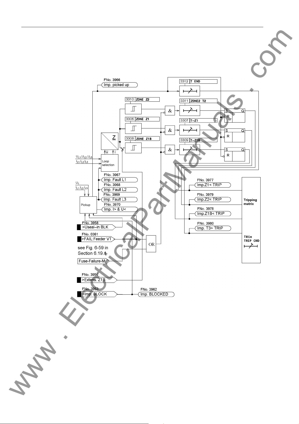
2 Functions
www . ElectricalPartManuals . com
A drop-out can only be caused by a drop-out of the overcurrent pickup and not by
exiting the tripping polygon.
The following figure shows the logic diagram for the impedance protection.
Figure 2-29 Logic Diagram of the Impedance Protection
2.14.2 Setting Notes
General Machine impedance protection is only effective and available if enabled during config-
uration (Section 2.2, address 133, IMPEDANCE PROT. = Enabled. If the function is
not required Disabled is set. Address 3301 IMPEDANCE PROT. serves to switch
the function ON or OFF or to block only the trip command (Block relay).
96
7UM61 Manual
C53000-G1176-C127-3
Page 97

2.14 Impedance Protection (ANSI 21)
www . ElectricalPartManuals . com
Pickup The maximum load current during operation is the most important criterion for setting
overcurrent pickup. A pickup by an overload must be excluded! For this reason, the
3302 IMP I> pickup value must be set above the maximum (over) load current to be
expected. Recommended setting: 1.2 to 1.5 times the nominal machine current. The
pickup logic corresponds to the logic of the definite time-overcurrent protection.
If the excitation is derived from the generator terminals with the short circuit current
possibly falling below the pickup value (address 3302) due to the collapsing voltage,
the undervoltage seal-in feature of the pickup is used, i.e. address 3303 U< SEAL-
IN is switched to ON.
The undervoltage seal-in setting U< (address 3304) is set to a value just below the
lowest phase-to-phase voltage occurring during operation, e.g. to U< = 75 % to 80 %
of the nominal voltage. The seal-in time (address 3305 T-SEAL-IN) must exceed the
maximum fault clearance time in a back-up case (recommended setting: Address
3312 T END + 1 s).
Impedance Stages The protection has the following characteristics which may be set independently:
1. Zone (fast tripping zone Z1 ) with parameters
ZONE Z1 Reactance = reach,
T-Z1 = 0 or short delay, if required.
Overreach zone Z1B, externally controlled via binary input, with parameters
ZONE Z1B Reactance = reach,
T-Z1B T1B = 0 or short delay, if required.
2. Zone (zone Z2) with parameters
ZONE Z2 Reactance = reach,
ZONE2 T2 The user must select a value for T2 above the grading
time of the network protection.
Non-directional final stage with parameter
T END The user must select T END so that the 2nd or 3rd
stage of the series-connected power system distance
protection is overreached.
As the user may assume that impedance protection measurement extends into the
unit transformer, parametrization selection must sufficiently consider the transformer
control range.
Therefore ZONE Z1 is normally set to a reach of approx. 70 % of the protected zone
(i.e. about 70 % of the transformer reactance), with no or only a small delay (i.e. T-Z1
= 0.00 s to 0.50 s). Protection then switches off faults on this distance after its operating time or with a slight time delay (high speed tripping). A time delay of 0.1 s is preferred.
For ZONE Z2 the reach could be set to about 100 % of the transformer reactance, or
in addition to a network impedance. The corresponding ZONE2 T2 time stage is to be
set so that it overreaches the power system protective equipment of the following
lines. The T END time is the last back-up time.
7UM61 Manual
C53000-G1176-C127-3
97
Page 98
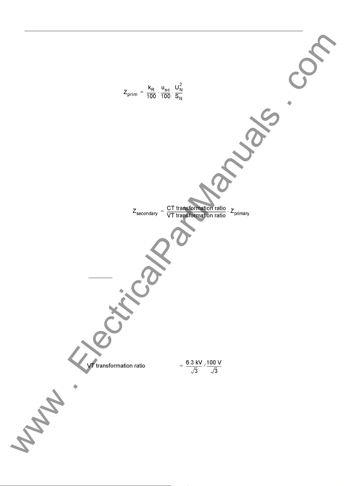
2 Functions
www . ElectricalPartManuals . com
The following formula is generally valid for the primary impedance (with limiting to the
unit transformer):
with
k
Protection zone reach [%]
R
u
Relative transformer short-circuit voltage [%]
K
S
Rated transformer power [MVA]
N
U
Machine-side rated transformer voltage [kV]
N
The derived primary impedances must be converted for the secondary side of the
current and voltage transformers. In general:
The nominal current of the protection device (= secondary nominal current of the
current transformer) is automatically considered by the device. You have already communicated the transformation ratios of the current and voltage transformers to the
device by entering the nominal transformer values (see section 2.3).
Example:
Transformer data:
u
= 7 %
K
S
= 5.3 MVA
N
U
= 6.3 kV
N
Transformation ratios:
Current transformer ratio = 500 A / 1 A
98
7UM61 Manual
C53000-G1176-C127-3
Page 99
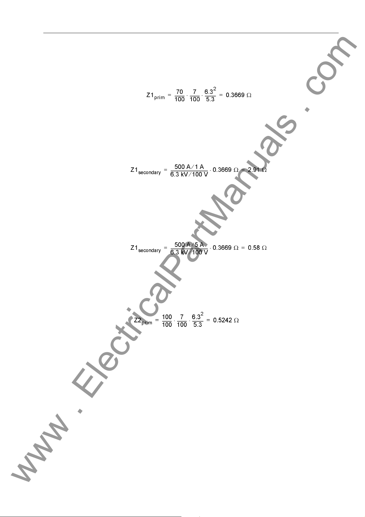
2.14 Impedance Protection (ANSI 21)
www . ElectricalPartManuals . com
This results to a 70 % reach for zone 1:
The following secondary side setting value of zone 1 results at address 3306 ZONE
Z1:
Note: The following ratio would result from the connection of a 5 A device to a 5 A
current transformer:
Likewise the following primary reactance results for a 100 % reach for zone 2:
7UM61 Manual
C53000-G1176-C127-3
99
Page 100

2 Functions
www . ElectricalPartManuals . com
The following secondary side setting value of zone 2 results at address 3310 ZONE
Z2:
Figure 2-30 Time Grading for Machine Impedance Protection – Example
Z1B Overreach Zone
Final Stage For short circuits outside the Z1 and Z2 zones, the device functions as a time-delayed
The Z1B overreach zone (address 3308 ZONE Z1B) is an externally controlled stage.
It does not influence the Z1 zone normal stage. Consequently there is no changeover,
but the overreach zone is enabled or disabled depending on the position of the highvoltage side circuit breaker.
The Z1B zone is usually enabled by an opened high-voltage circuit breaker. In this
case every impedance protection pickup can only be due to a fault in the protection
zone of the block, since the power system is disconnected from the block. Consequently the fast tripping zone can be extended to between 100 % and 120 % of the
protection zone without any loss of selectivity.
The Z1B zone is activated via a binary input controlled by the circuit breaker auxiliary
contact (see Figure 2-30). The overreach zone is allocated an individual 3309 T-Z1B
time delay.
overcurrent protection. Its nondirectional final time T END is selected so that its time
value overreaches the second or third stage of the series-connected network distance
protection.
100
7UM61 Manual
C53000-G1176-C127-3
 Loading...