

Siemens SIPROTEC 7ST6 User Manual

SIPROTEC
www . ElectricalPartManuals . com
Preface
Introduction 1
Functions 2
Mounting and Commissioning 3
Numerical Overhead
Contact Line Protection for
AC Traction Power Supply
7ST6
V4.2
Manual
Technical Data 4
Appendix A
Literature
Glossary
Index
E50417-G1176-C251-A3

Disclaimer of liability
www . ElectricalPartManuals . com
We have checked the text of this manual against the hardware
and software described. However, deviations from the description cannot be completely ruled out, so that no liability can be accepted for any errors or omissions contained in the information
given.
The information given in this document is reviewed regularly and
any necessary corrections will be included in subsequent editions. We appreciate any suggestions for improvement.
We reserve the right to make technical improvements without
notice.
Copyright
Copyright © Siemens AG 2006. All rights reserved.
Dissemination or reproduction of this document, or evaluation
and communication of its contents, is not authorized except
where expressly permitted. Violations are liable for damages. All
rights reserved, particularly for the purposes of patent application
or trademark registration.
Registered Trademarks
SIPROTEC, SINAUT , SICAM, SITRAS and DIGSI are registered
trademarks of SIEMENS AG. Other designations in this manual
might be trademarks whose use by third parties for their own purposes would infringe the rights of the owner.
Document Release 4.10.01
7ST6 Manual
E50417-G1176-C251-A3

Preface
www . ElectricalPartManuals . com
Purpose of this Manual
Target Audience Protection engineers, commissioning en gin eers, personnel concerned with adjust-
Validity of the Manual
Indication of Conformity
This manual describes the functions, operation, mounting, and placing into service of
device 7ST6. In particular, one will find:
• Information on how to configure the device scope and a description of the device
functions and setting options;
• Instructions for mounting and commissioning;
• Compilation of the technical specifications;
• Summary of the most significant data for the experienced user in the Appendix.
General information about design, configuration, and operati on of SIPROTEC 4
devices are laid down in the SIPROTEC 4 System Description.
ment, checking, and service of selective protective equipment, automatic and control
facilities, and personnel of electrical facilities and power plants.
®
This manual is valid for: SIPROTEC
for AC Traction Power Supply 7ST6 ; Firmware version V4.2.
This product complies with the directive of the Council of the European Communities on the approximation of the laws of the Member States relating to electromagnetic compatibility (EMC Council Directive 89/336/EEC) and concerning electrical
equipment for use within specified voltage limits (Low-voltage directive 73/23
EEC).
This conformity is proved by tests conducted by Siemens AG in accordance with
Article 10 of the Council Directives in agreement with the generic standards
EN61000-6-2 and EN 61000-6-4 for the EMC directive, and with the standard EN
60255-6 for the low-voltage directive.
This device is designed and produced for industrial use.
The product conforms with the international standard of the series IEC 60255 and
the German standard VDE 0435.
4 Numerical Overhead Contact Line Protection
Additional Support Should you have any further questions regarding the SIPROTEC 4 system please
contact your local Siemens distributor.
Additional information:
E50417-G1176-C251-A3
Internet:
In order to remain up-to-date in the future, please make use of the o ffer on our down-
load platform on the Internet under address:
http://www.siprotec.de
37ST6 Manual
Preface
www . ElectricalPartManuals . com
Instructions and
Warnings
Should you experience any problems in using SIPROTEC 4, please contact our
Hotline
Telephone: +49 - 180 - 524 7000
Fax: +49 - 180 - 524 2471
E-mail: services@ptd.siemens.de
The warnings and notes contained in this man ual serve for your own safety and for
an appropriate lifetime of the device. Please observe them!
The following indicators and standard definitions are used:
DANGER!
indicates that death, severe personal injury or substantial property damage can
result if proper precautions are not taken.
Warning
indicates that death, severe personal injury or substantial property damage can
result if proper precautions are not taken.
Caution
indicates that minor personal injury or property damage can result if proper precautions are not taken. This p articularly applies to damage on or in the device itself and
consequential damage thereof.
Note:
indicates information about the device or respective part of the instruction manual
which is essential to highlight.
WARNING!
Hazardous voltages are present in this electrical equip m en t du ring ope ra tio n.
Death, severe personal injury or substantial property d ama ge ca n r esult if the device
is not handled properly.
Only qualified personnel shall work on and in the vicinity of this equipment. The per-
sonnel must be thoroughly familiar with all warnings and maintenance procedures of
this manual as well as the safety regulations.
Successful and safe operation of the device is dependent on proper transportation,
storage, mounting and assembly and the observance of the warnings and instructions
of the unit manual.
In particular, the general installation and safety regulations for work in power current
plants (e.g. ANSI, IEC, EN, DIN, or other national and international regulations) must
be observed.
4
E50417-G1176-C251-A3
7ST6 Manual
Definition QUALIFIED PERSONNEL
www . ElectricalPartManuals . com
Prerequisites to proper and safe operation of this product are proper transport,
proper storage, setup, installation, operation, and maintenance of the product, as
well as careful operation and servicing of the device within the scope of the warnings and instructions of this manual. Qualifications are:
• Training and Instruction to energize, de-energize, clear, gr ound and tag circuits
and equipment in accordance with established safety practices.
• Training and instruction (or other qualification) for switching, earthing, and designating devices and systems.
• Training in rendering first aid.
Typographic and
Graphical Conventions
To designate terms which refer in the text to information of the device or for the
device, the following fonts are used:
Parameter names
Designators of configuration or function parameters which may appear word-forword in the display of the device or on the screen of a personal computer (with
DIGSI), are marked in bold letters of a monospace font. The same goes for the titles
of menus.
1234A
Parameter addresses have the same character style as p arameter names. Parameter addresses in overview tables contain the suffix A, if the p arameter is only available using the option Display additional settings.
Parameter Conditions
Possible settings of text parameters, which may appear word-for-word in the
display of the device or on the screen of a personal computer (with operation software DIGSI), are additionally written in italics. The same goes for the op tions of the
menus.
„Annunciations“
Designators for information, which may be output by the relay or requ ired from other
devices or from the switch gear , are marked in a monosp ace type style in quot ation
marks.
Preface
7ST6 Manual
E50417-G1176-C251-A3
Deviations may be permitted in drawings and tables when the type of de signato r can
be obviously derived from the illustration.
The following symbols are used in drawings:
Device-internal logical input signal
Device-internal (logical) output signal
Internal input signal of an analog quantity
External binary input signal with number (binary input, input
indication)
External binary output signal with number (device indication)
5
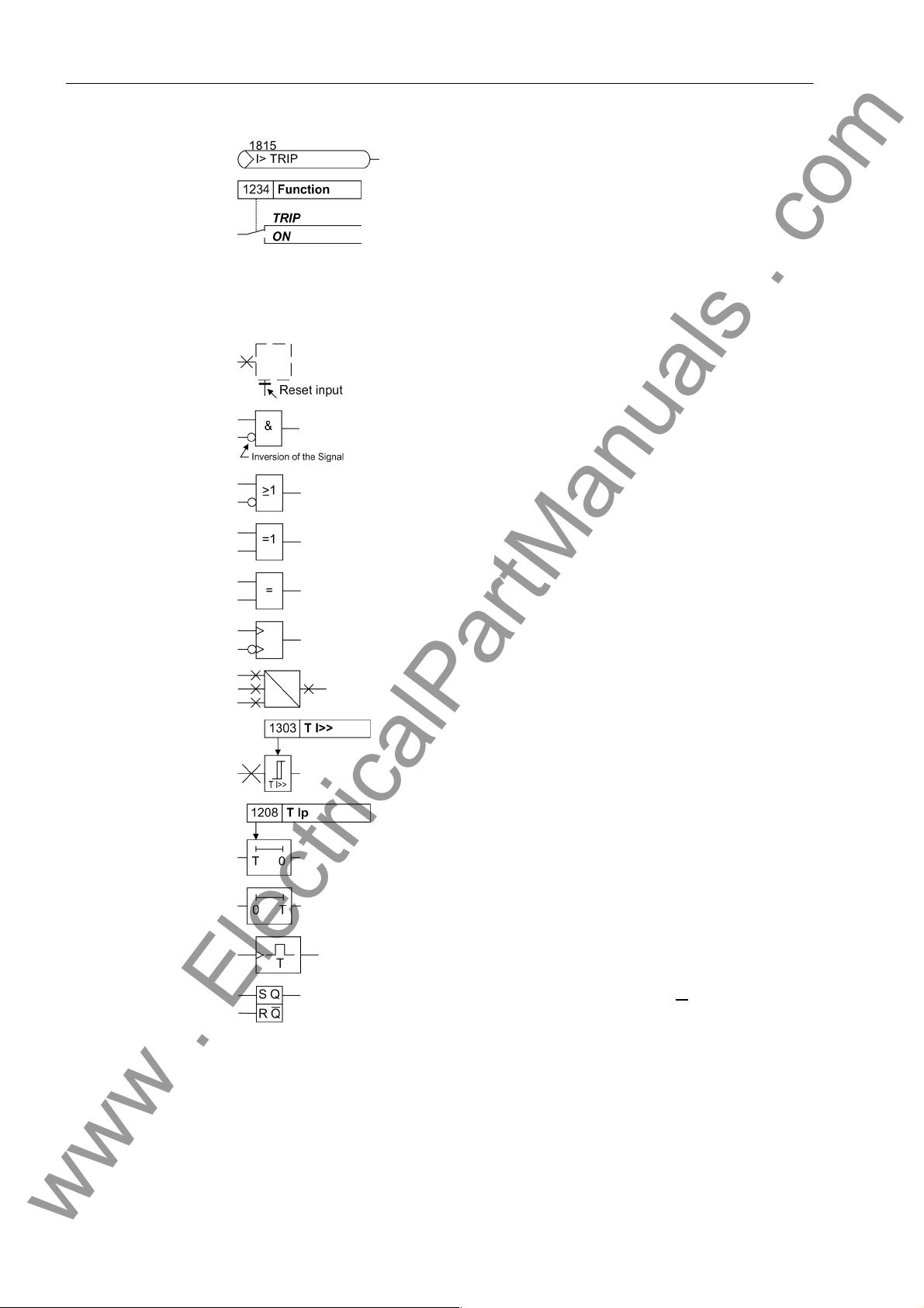
Preface
www . ElectricalPartManuals . com
External binary output signal with number (de vice indication)
used as input signal
Example of a parameter switch designated FUNCTION with
the address 1234 and the possible settings ON and OFF
Besides these, graphical symbols are used according to IEC 60617-12 and IEC
60617-13 or symbols derived from these st andards. Some of the most frequently used
are listed below:
Input signal of an analog quantity
AND gate
OR gate
Exclusive OR (antivalence): output is active, if only one of
the inputs is active
Coincidence gate (equivalence): output is active if both
inputs are active or inactive at the same time
Dynamic inputs (edge–triggered) above with positive, below
with negative edge
Formation of one analog output signal from a number of
analog input signals
Limit stage with setting address and parameter designator
(name)
Timer (pickup delay T, example adjustable) with setting
address and parameter designator (name)
Timer (dropout delay T, example non-adjustable)
Dynamic triggered pulse timer T (monoflop)
Static memory (RS-flipflop) with setting input (S), resetting
input (R), output (Q) and inverted output (Q
■
6
)
7ST6 Manual
E50417-G1176-C251-A3

Contents
www . ElectricalPartManuals . com
1 Introduction. . . . . . . . . . . . . . . . . . . . . . . . . . . . . . . . . . . . . . . . . . . . . . . . . . . . . . . . . . . . . . . . . . . . 15
1.1 Overall Operation . . . . . . . . . . . . . . . . . . . . . . . . . . . . . . . . . . . . . . . . . . . . . . . . . . . . . . . . 16
1.2 Application Scope . . . . . . . . . . . . . . . . . . . . . . . . . . . . . . . . . . . . . . . . . . . . . . . . . . . . . . . . 19
1.3 Characteristics. . . . . . . . . . . . . . . . . . . . . . . . . . . . . . . . . . . . . . . . . . . . . . . . . . . . . . . . . . . 21
2 Functions. . . . . . . . . . . . . . . . . . . . . . . . . . . . . . . . . . . . . . . . . . . . . . . . . . . . . . . . . . . . . . . . . . . . . . 25
2.1 General . . . . . . . . . . . . . . . . . . . . . . . . . . . . . . . . . . . . . . . . . . . . . . . . . . . . . . . . . . . . . . . 26
2.1.1 Functional Scope. . . . . . . . . . . . . . . . . . . . . . . . . . . . . . . . . . . . . . . . . . . . . . . . . . . . . . . . . 26
2.1.1.1 Configuration of the Functional Scope . . . . . . . . . . . . . . . . . . . . . . . . . . . . . . . . . . . . . . . . 26
2.1.1.2 Setting Notes. . . . . . . . . . . . . . . . . . . . . . . . . . . . . . . . . . . . . . . . . . . . . . . . . . . . . . . . . . . . 27
2.1.1.3 Settings . . . . . . . . . . . . . . . . . . . . . . . . . . . . . . . . . . . . . . . . . . . . . . . . . . . . . . . . . . . . . . . . 29
2.1.2 Device . . . . . . . . . . . . . . . . . . . . . . . . . . . . . . . . . . . . . . . . . . . . . . . . . . . . . . . . . . . . . . . . . 30
2.1.2.1 Trip Dependent Indications . . . . . . . . . . . . . . . . . . . . . . . . . . . . . . . . . . . . . . . . . . . . 30
2.1.2.2 Spontaneous Indications on the Display . . . . . . . . . . . . . . . . . . . . . . . . . . . . . . . . . . . . . . . 30
2.1.2.3 Setting Notes. . . . . . . . . . . . . . . . . . . . . . . . . . . . . . . . . . . . . . . . . . . . . . . . . . . . . . . . . . . . 30
2.1.2.4 Settings . . . . . . . . . . . . . . . . . . . . . . . . . . . . . . . . . . . . . . . . . . . . . . . . . . . . . . . . . . . . . . . . 31
2.1.2.5 Information List . . . . . . . . . . . . . . . . . . . . . . . . . . . . . . . . . . . . . . . . . . . . . . . . . . . . . . . . . . 31
2.1.3 Power System Data 1 . . . . . . . . . . . . . . . . . . . . . . . . . . . . . . . . . . . . . . . . . . . . . . . . . . . . . 33
2.1.3.1 Setting Notes. . . . . . . . . . . . . . . . . . . . . . . . . . . . . . . . . . . . . . . . . . . . . . . . . . . . . . . . . . . . 33
2.1.3.2 Settings . . . . . . . . . . . . . . . . . . . . . . . . . . . . . . . . . . . . . . . . . . . . . . . . . . . . . . . . . . . . . . . . 36
2.1.3.3 Information List . . . . . . . . . . . . . . . . . . . . . . . . . . . . . . . . . . . . . . . . . . . . . . . . . . . . . . . . . . 37
2.1.4 Change Group. . . . . . . . . . . . . . . . . . . . . . . . . . . . . . . . . . . . . . . . . . . . . . . . . . . . . . . . . . . 38
2.1.4.1 Purpose of the Setting Groups . . . . . . . . . . . . . . . . . . . . . . . . . . . . . . . . . . . . . . . . . . . . . . 38
2.1.4.2 Setting Notes. . . . . . . . . . . . . . . . . . . . . . . . . . . . . . . . . . . . . . . . . . . . . . . . . . . . . . . . . . . . 38
2.1.4.3 Settings . . . . . . . . . . . . . . . . . . . . . . . . . . . . . . . . . . . . . . . . . . . . . . . . . . . . . . . . . . . . . . . . 39
2.1.4.4 Information List . . . . . . . . . . . . . . . . . . . . . . . . . . . . . . . . . . . . . . . . . . . . . . . . . . . . . . . . . . 39
2.1.5 Power System Data 2 . . . . . . . . . . . . . . . . . . . . . . . . . . . . . . . . . . . . . . . . . . . . . . . . . . . . . 40
2.1.5.1 Setting Notes. . . . . . . . . . . . . . . . . . . . . . . . . . . . . . . . . . . . . . . . . . . . . . . . . . . . . . . . . . . . 40
2.1.5.2 Settings . . . . . . . . . . . . . . . . . . . . . . . . . . . . . . . . . . . . . . . . . . . . . . . . . . . . . . . . . . . . . . . . 41
2.1.5.3 Information List . . . . . . . . . . . . . . . . . . . . . . . . . . . . . . . . . . . . . . . . . . . . . . . . . . . . . . . . . . 43
2.1.6 Oscillographic Fault Records. . . . . . . . . . . . . . . . . . . . . . . . . . . . . . . . . . . . . . . . . . . . . . . . 44
2.1.6.1 Functional Description . . . . . . . . . . . . . . . . . . . . . . . . . . . . . . . . . . . . . . . . . . . . . . . 44
2.1.6.2 Setting Notes. . . . . . . . . . . . . . . . . . . . . . . . . . . . . . . . . . . . . . . . . . . . . . . . . . . . . . . . . . . . 45
2.1.6.3 Settings . . . . . . . . . . . . . . . . . . . . . . . . . . . . . . . . . . . . . . . . . . . . . . . . . . . . . . . . . . . . . . . . 46
2.1.6.4 Information List . . . . . . . . . . . . . . . . . . . . . . . . . . . . . . . . . . . . . . . . . . . . . . . . . . . . . . . . . . 46
77ST6 Manual
E50417-G1176-C251-A3

Contents
www . ElectricalPartManuals . com
2.2 Distance Protection . . . . . . . . . . . . . . . . . . . . . . . . . . . . . . . . . . . . . . . . . . . . . . . . . . . . . . . 47
2.2.1 Enabling the Distance Protection. . . . . . . . . . . . . . . . . . . . . . . . . . . . . . . . . . . . . . . . . . . . . 47
2.2.2 Distance Protection with Combined Tripping Characteristic . . . . . . . . . . . . . . . . . . . . . . . . 48
2.2.3 Distance Protection with Polygonal Tripping Characteristic . . . . . . . . . . . . . . . . . . . . . . . . 50
2.2.4 Short-circuit Detection by Current and Voltage Angle Changes . . . . . . . . . . . . . . . . . . . . . 52
2.2.5 Tripping Logic of the Distance Protection . . . . . . . . . . . . . . . . . . . . . . . . . . . . . . . . . . . . . . 54
2.2.6 Tripping Characteristic for Manual Reclose. . . . . . . . . . . . . . . . . . . . . . . . . . . . . . . . . . . . . 57
2.2.7 Tripping Characteristic for Manual Close. . . . . . . . . . . . . . . . . . . . . . . . . . . . . . . . . . . . . . . 58
2.2.8 Zone Changeover (only for 16.7 Hz) . . . . . . . . . . . . . . . . . . . . . . . . . . . . . . . . . . . . . . . . . . 59
2.2.9 Setting Notes. . . . . . . . . . . . . . . . . . . . . . . . . . . . . . . . . . . . . . . . . . . . . . . . . . . . . . . . . . . . 60
2.2.10 Settings . . . . . . . . . . . . . . . . . . . . . . . . . . . . . . . . . . . . . . . . . . . . . . . . . . . . . . . . . . . . . . . . 69
2.2.11 Information List . . . . . . . . . . . . . . . . . . . . . . . . . . . . . . . . . . . . . . . . . . . . . . . . . . . . . . . . . . 74
2.3 Overcurrent Protection. . . . . . . . . . . . . . . . . . . . . . . . . . . . . . . . . . . . . . . . . . . . . . . . . . . . . 76
2.3.1 Functional Description. . . . . . . . . . . . . . . . . . . . . . . . . . . . . . . . . . . . . . . . . . . . . . . . . . . . . 76
2.3.2 Setting Notes. . . . . . . . . . . . . . . . . . . . . . . . . . . . . . . . . . . . . . . . . . . . . . . . . . . . . . . . . . . . 79
2.3.3 Settings . . . . . . . . . . . . . . . . . . . . . . . . . . . . . . . . . . . . . . . . . . . . . . . . . . . . . . . . . . . . . . . . 82
2.3.4 Information List . . . . . . . . . . . . . . . . . . . . . . . . . . . . . . . . . . . . . . . . . . . . . . . . . . . . . . . . . . 83
2.4 High-Speed Overcurrent Protection. . . . . . . . . . . . . . . . . . . . . . . . . . . . . . . . . . . . . . . . . . . 84
2.4.1 Functional Description. . . . . . . . . . . . . . . . . . . . . . . . . . . . . . . . . . . . . . . . . . . . . . . . . . . . . 84
2.4.2 Setting Notes. . . . . . . . . . . . . . . . . . . . . . . . . . . . . . . . . . . . . . . . . . . . . . . . . . . . . . . . . . . . 85
2.4.3 Settings . . . . . . . . . . . . . . . . . . . . . . . . . . . . . . . . . . . . . . . . . . . . . . . . . . . . . . . . . . . . . . . . 86
2.4.4 Information List . . . . . . . . . . . . . . . . . . . . . . . . . . . . . . . . . . . . . . . . . . . . . . . . . . . . . . . . . . 86
2.5 Emergency Overcurrent Protection . . . . . . . . . . . . . . . . . . . . . . . . . . . . . . . . . . . . . . . . . . . 87
2.5.1 General . . . . . . . . . . . . . . . . . . . . . . . . . . . . . . . . . . . . . . . . . . . . . . . . . . . . . . . . . . . . . . . . 87
2.5.2 Functional Description. . . . . . . . . . . . . . . . . . . . . . . . . . . . . . . . . . . . . . . . . . . . . . . . . . . . . 87
2.5.3 Setting Notes. . . . . . . . . . . . . . . . . . . . . . . . . . . . . . . . . . . . . . . . . . . . . . . . . . . . . . . . . . . . 88
2.5.4 Settings . . . . . . . . . . . . . . . . . . . . . . . . . . . . . . . . . . . . . . . . . . . . . . . . . . . . . . . . . . . . . . . . 89
2.5.5 Information List . . . . . . . . . . . . . . . . . . . . . . . . . . . . . . . . . . . . . . . . . . . . . . . . . . . . . . . . . . 89
2.6 Overvoltage and Undervoltage Protection. . . . . . . . . . . . . . . . . . . . . . . . . . . . . . . . . . . . . . 90
2.6.1 Overvoltage Protection . . . . . . . . . . . . . . . . . . . . . . . . . . . . . . . . . . . . . . . . . . . . . . . . . . . . 90
2.6.2 Undervoltage Protection . . . . . . . . . . . . . . . . . . . . . . . . . . . . . . . . . . . . . . . . . . . . . . . . . . . 91
2.6.3 Setting Notes. . . . . . . . . . . . . . . . . . . . . . . . . . . . . . . . . . . . . . . . . . . . . . . . . . . . . . . . . . . . 92
2.6.4 Settings . . . . . . . . . . . . . . . . . . . . . . . . . . . . . . . . . . . . . . . . . . . . . . . . . . . . . . . . . . . . . . . . 93
2.6.5 Information List . . . . . . . . . . . . . . . . . . . . . . . . . . . . . . . . . . . . . . . . . . . . . . . . . . . . . . . . . . 93
2.7 Thermal Overload Protection. . . . . . . . . . . . . . . . . . . . . . . . . . . . . . . . . . . . . . . . . . . . . . . . 94
2.7.1 Thermal Overload Protection. . . . . . . . . . . . . . . . . . . . . . . . . . . . . . . . . . . . . . . . . . . . . . . . 94
2.7.2 Ambient Temperature Sensing . . . . . . . . . . . . . . . . . . . . . . . . . . . . . . . . . . . . . . . . . . . . . . 95
2.7.3 Catenary Changeover . . . . . . . . . . . . . . . . . . . . . . . . . . . . . . . . . . . . . . . . . . . . . . . . . . . . . 97
2.7.4 Setting Notes. . . . . . . . . . . . . . . . . . . . . . . . . . . . . . . . . . . . . . . . . . . . . . . . . . . . . . . . . . . . 99
2.7.5 Settings . . . . . . . . . . . . . . . . . . . . . . . . . . . . . . . . . . . . . . . . . . . . . . . . . . . . . . . . . . . . . . . 101
2.7.6 Information List . . . . . . . . . . . . . . . . . . . . . . . . . . . . . . . . . . . . . . . . . . . . . . . . . . . . . . . . . 101
8
E50417-G1176-C251-A3
7ST6 Manual

Contents
www . ElectricalPartManuals . com
2.8 Circuit Breaker Failure Protection . . . . . . . . . . . . . . . . . . . . . . . . . . . . . . . . . . . . . . . . . . . 103
2.8.1 Functional Description. . . . . . . . . . . . . . . . . . . . . . . . . . . . . . . . . . . . . . . . . . . . . . . . . . . . 103
2.8.2 Setting Notes. . . . . . . . . . . . . . . . . . . . . . . . . . . . . . . . . . . . . . . . . . . . . . . . . . . . . . . . . . . 106
2.8.3 Settings . . . . . . . . . . . . . . . . . . . . . . . . . . . . . . . . . . . . . . . . . . . . . . . . . . . . . . . . . . . . . . . 108
2.8.4 Information List . . . . . . . . . . . . . . . . . . . . . . . . . . . . . . . . . . . . . . . . . . . . . . . . . . . . . . . . . 108
2.9 Trip Supervision. . . . . . . . . . . . . . . . . . . . . . . . . . . . . . . . . . . . . . . . . . . . . . . . . . . . . . . . . 109
2.9.1 Functional Description. . . . . . . . . . . . . . . . . . . . . . . . . . . . . . . . . . . . . . . . . . . . . . . . . . . . 109
2.9.2 Setting Notes. . . . . . . . . . . . . . . . . . . . . . . . . . . . . . . . . . . . . . . . . . . . . . . . . . . . . . . . . . . .110
2.9.3 Settings . . . . . . . . . . . . . . . . . . . . . . . . . . . . . . . . . . . . . . . . . . . . . . . . . . . . . . . . . . . . . . . .110
2.9.4 Information List . . . . . . . . . . . . . . . . . . . . . . . . . . . . . . . . . . . . . . . . . . . . . . . . . . . . . . . . . .110
2.10 Defrosting Protection. . . . . . . . . . . . . . . . . . . . . . . . . . . . . . . . . . . . . . . . . . . . . . . . . . . . . .111
2.10.1 Functional Description . . . . . . . . . . . . . . . . . . . . . . . . . . . . . . . . . . . . . . . . . . . . . . . .111
2.10.2 Setting Notes. . . . . . . . . . . . . . . . . . . . . . . . . . . . . . . . . . . . . . . . . . . . . . . . . . . . . . . . . . . .117
2.10.3 Settings . . . . . . . . . . . . . . . . . . . . . . . . . . . . . . . . . . . . . . . . . . . . . . . . . . . . . . . . . . . . . . . .119
2.10.4 Information List . . . . . . . . . . . . . . . . . . . . . . . . . . . . . . . . . . . . . . . . . . . . . . . . . . . . . . . . . .119
2.11 InRush Restraint . . . . . . . . . . . . . . . . . . . . . . . . . . . . . . . . . . . . . . . . . . . . . . . . . . . . . . . . 120
2.11.1 Functional Description. . . . . . . . . . . . . . . . . . . . . . . . . . . . . . . . . . . . . . . . . . . . . . . . . . . . 120
2.11.2 Setting Notes. . . . . . . . . . . . . . . . . . . . . . . . . . . . . . . . . . . . . . . . . . . . . . . . . . . . . . . . . . . 122
2.11.3 Settings . . . . . . . . . . . . . . . . . . . . . . . . . . . . . . . . . . . . . . . . . . . . . . . . . . . . . . . . . . . . . . . 123
2.11.4 Information List . . . . . . . . . . . . . . . . . . . . . . . . . . . . . . . . . . . . . . . . . . . . . . . . . . . . . . . . . 123
2.12 Automatic Reclosure Function. . . . . . . . . . . . . . . . . . . . . . . . . . . . . . . . . . . . . . . . . . . . . . 124
2.12.1 Functional Description . . . . . . . . . . . . . . . . . . . . . . . . . . . . . . . . . . . . . . . . . . . . . . . . 124
2.12.2 Setting Notes. . . . . . . . . . . . . . . . . . . . . . . . . . . . . . . . . . . . . . . . . . . . . . . . . . . . . . . . . . . 131
2.12.3 Settings . . . . . . . . . . . . . . . . . . . . . . . . . . . . . . . . . . . . . . . . . . . . . . . . . . . . . . . . . . . . . . . 139
2.12.4 Information List . . . . . . . . . . . . . . . . . . . . . . . . . . . . . . . . . . . . . . . . . . . . . . . . . . . . . . . . . 140
2.13 Synchronism and Voltage Check. . . . . . . . . . . . . . . . . . . . . . . . . . . . . . . . . . . . . . . . . . . . 142
2.13.1 Functional Description . . . . . . . . . . . . . . . . . . . . . . . . . . . . . . . . . . . . . . . . . . . . . . . 142
2.13.2 Setting Notes. . . . . . . . . . . . . . . . . . . . . . . . . . . . . . . . . . . . . . . . . . . . . . . . . . . . . . . . . . . 145
2.13.3 Settings . . . . . . . . . . . . . . . . . . . . . . . . . . . . . . . . . . . . . . . . . . . . . . . . . . . . . . . . . . . . . . . 150
2.13.4 Information List . . . . . . . . . . . . . . . . . . . . . . . . . . . . . . . . . . . . . . . . . . . . . . . . . . . . . . . . . 151
2.14 Fault Locator . . . . . . . . . . . . . . . . . . . . . . . . . . . . . . . . . . . . . . . . . . . . . . . . . . . . . . . . . . . 152
2.14.1 Functional Description. . . . . . . . . . . . . . . . . . . . . . . . . . . . . . . . . . . . . . . . . . . . . . . . . . . . 152
2.14.2 Setting Notes. . . . . . . . . . . . . . . . . . . . . . . . . . . . . . . . . . . . . . . . . . . . . . . . . . . . . . . . . . . 154
2.14.3 Settings . . . . . . . . . . . . . . . . . . . . . . . . . . . . . . . . . . . . . . . . . . . . . . . . . . . . . . . . . . . . . . . 155
2.14.4 Information List . . . . . . . . . . . . . . . . . . . . . . . . . . . . . . . . . . . . . . . . . . . . . . . . . . . . . . . . . 155
2.15 It Function (current-time integral) . . . . . . . . . . . . . . . . . . . . . . . . . . . . . . . . . . . . . . . . . . . 156
2.15.1 Function Description It Procedure. . . . . . . . . . . . . . . . . . . . . . . . . . . . . . . . . . . . . . . . . . . 156
2.15.2 Function Description 2P-procedure. . . . . . . . . . . . . . . . . . . . . . . . . . . . . . . . . . . . . . . . . . 159
2.15.3 Setting Notes. . . . . . . . . . . . . . . . . . . . . . . . . . . . . . . . . . . . . . . . . . . . . . . . . . . . . . . . . . . 163
2.15.4 Settings . . . . . . . . . . . . . . . . . . . . . . . . . . . . . . . . . . . . . . . . . . . . . . . . . . . . . . . . . . . . . . . 165
2.15.5 Information List . . . . . . . . . . . . . . . . . . . . . . . . . . . . . . . . . . . . . . . . . . . . . . . . . . . . . . . . . 165
7ST6 Manual
E50417-G1176-C251-A3
9

Contents
www . ElectricalPartManuals . com
2.16 Monitoring Function. . . . . . . . . . . . . . . . . . . . . . . . . . . . . . . . . . . . . . . . . . . . . . . . . . . . . . 166
2.16.1 Hardware Monitoring . . . . . . . . . . . . . . . . . . . . . . . . . . . . . . . . . . . . . . . . . . . . . . . . . . . . . 166
2.16.2 Software Monitoring. . . . . . . . . . . . . . . . . . . . . . . . . . . . . . . . . . . . . . . . . . . . . . . . . . . . . . 167
2.16.3 Fuse Failure Monitor . . . . . . . . . . . . . . . . . . . . . . . . . . . . . . . . . . . . . . . . . . . . . . . . . . . . . 167
2.16.4 Setting Notes. . . . . . . . . . . . . . . . . . . . . . . . . . . . . . . . . . . . . . . . . . . . . . . . . . . . . . . . . . . 169
2.16.5 Settings . . . . . . . . . . . . . . . . . . . . . . . . . . . . . . . . . . . . . . . . . . . . . . . . . . . . . . . . . . . . . . . 169
2.16.6 Information List . . . . . . . . . . . . . . . . . . . . . . . . . . . . . . . . . . . . . . . . . . . . . . . . . . . . . . . . . 169
2.17 Trip Circuit Supervision . . . . . . . . . . . . . . . . . . . . . . . . . . . . . . . . . . . . . . . . . . . . . . . . . . . 170
2.17.1 Functional Description. . . . . . . . . . . . . . . . . . . . . . . . . . . . . . . . . . . . . . . . . . . . . . . . . . . . 170
2.17.2 Setting Notes. . . . . . . . . . . . . . . . . . . . . . . . . . . . . . . . . . . . . . . . . . . . . . . . . . . . . . . . . . . 173
2.17.3 Settings . . . . . . . . . . . . . . . . . . . . . . . . . . . . . . . . . . . . . . . . . . . . . . . . . . . . . . . . . . . . . . . 173
2.17.4 Information List . . . . . . . . . . . . . . . . . . . . . . . . . . . . . . . . . . . . . . . . . . . . . . . . . . . . . . . . . 173
2.18 Protection Function Control. . . . . . . . . . . . . . . . . . . . . . . . . . . . . . . . . . . . . . . . . . . . . . . . 174
2.18.1 General . . . . . . . . . . . . . . . . . . . . . . . . . . . . . . . . . . . . . . . . . . . . . . . . . . . . . . . . . . . . . . . 174
2.18.1.1 Line Energization Recognition. . . . . . . . . . . . . . . . . . . . . . . . . . . . . . . . . . . . . . . . . . . . . . 174
2.18.1.2 Detection of the Circuit Breaker Position . . . . . . . . . . . . . . . . . . . . . . . . . . . . . . . . 176
2.18.1.3 Pickup Logic for the Entire Device . . . . . . . . . . . . . . . . . . . . . . . . . . . . . . . . . . . . . 177
2.18.1.4 Tripping Logic of the Entire Device . . . . . . . . . . . . . . . . . . . . . . . . . . . . . . . . . . . . . 178
2.18.1.5 Pickup of the Automatic Test Unit for the Overhead Contact Line (only for 16.7 Hz) . . . . 182
2.18.1.6 Setting Notes. . . . . . . . . . . . . . . . . . . . . . . . . . . . . . . . . . . . . . . . . . . . . . . . . . . . . . . . . . . 183
2.18.2 Testing . . . . . . . . . . . . . . . . . . . . . . . . . . . . . . . . . . . . . . . . . . . . . . . . . . . . . . . . . . . . . . . . 184
2.18.2.1 Functional Description. . . . . . . . . . . . . . . . . . . . . . . . . . . . . . . . . . . . . . . . . . . . . . . . . . . . 184
2.18.2.2 Setting Notes. . . . . . . . . . . . . . . . . . . . . . . . . . . . . . . . . . . . . . . . . . . . . . . . . . . . . . . . . . . 185
2.18.2.3 Information List . . . . . . . . . . . . . . . . . . . . . . . . . . . . . . . . . . . . . . . . . . . . . . . . . . . . . . . . . 185
2.19 Auxiliary Functions. . . . . . . . . . . . . . . . . . . . . . . . . . . . . . . . . . . . . . . . . . . . . . . . . . . . . . . 186
2.19.1 Message Processing . . . . . . . . . . . . . . . . . . . . . . . . . . . . . . . . . . . . . . . . . . . . . . . . . . . . . 186
2.19.1.1 Functional Description. . . . . . . . . . . . . . . . . . . . . . . . . . . . . . . . . . . . . . . . . . . . . . . . . . . . 186
2.19.2 Measurement. . . . . . . . . . . . . . . . . . . . . . . . . . . . . . . . . . . . . . . . . . . . . . . . . . . . . . . . . . . 190
2.19.2.1 Functional Description. . . . . . . . . . . . . . . . . . . . . . . . . . . . . . . . . . . . . . . . . . . . . . . . . . . . 190
2.19.2.2 Information List . . . . . . . . . . . . . . . . . . . . . . . . . . . . . . . . . . . . . . . . . . . . . . . . . . . . . . . . . 191
2.19.3 Statistics. . . . . . . . . . . . . . . . . . . . . . . . . . . . . . . . . . . . . . . . . . . . . . . . . . . . . . . . . . . . . . . 192
2.19.3.1 Functional Description. . . . . . . . . . . . . . . . . . . . . . . . . . . . . . . . . . . . . . . . . . . . . . . . . . . . 192
2.19.3.2 Setting Notes. . . . . . . . . . . . . . . . . . . . . . . . . . . . . . . . . . . . . . . . . . . . . . . . . . . . . . . . . . . 193
2.19.3.3 Information List . . . . . . . . . . . . . . . . . . . . . . . . . . . . . . . . . . . . . . . . . . . . . . . . . . . . . . . . . 193
2.20 Command Processing . . . . . . . . . . . . . . . . . . . . . . . . . . . . . . . . . . . . . . . . . . . . . . . . . . . 194
2.20.1 Control Authorization. . . . . . . . . . . . . . . . . . . . . . . . . . . . . . . . . . . . . . . . . . . . . . . . . . . . . 194
2.20.1.1 Command Types . . . . . . . . . . . . . . . . . . . . . . . . . . . . . . . . . . . . . . . . . . . . . . . . . . . . . . 194
2.20.1.2 Sequence in the Command Path . . . . . . . . . . . . . . . . . . . . . . . . . . . . . . . . . . . . . . . . . . . 195
2.20.1.3 Interlocking . . . . . . . . . . . . . . . . . . . . . . . . . . . . . . . . . . . . . . . . . . . . . . . . . . . . . . . . . . . 196
2.20.1.4 Information List . . . . . . . . . . . . . . . . . . . . . . . . . . . . . . . . . . . . . . . . . . . . . . . . . . . . . . . . . 199
2.20.2 Control Device. . . . . . . . . . . . . . . . . . . . . . . . . . . . . . . . . . . . . . . . . . . . . . . . . . . . . . . . . . 200
2.20.2.1 Information List . . . . . . . . . . . . . . . . . . . . . . . . . . . . . . . . . . . . . . . . . . . . . . . . . . . . . . . . . 200
2.20.3 Process Data. . . . . . . . . . . . . . . . . . . . . . . . . . . . . . . . . . . . . . . . . . . . . . . . . . . . . . . . . . . 201
2.20.3.1 Method of Operation . . . . . . . . . . . . . . . . . . . . . . . . . . . . . . . . . . . . . . . . . . . . . . . . . . . . . 201
2.20.4 Protocol . . . . . . . . . . . . . . . . . . . . . . . . . . . . . . . . . . . . . . . . . . . . . . . . . . . . . . . . . . . . . . . 202
2.20.4.1 Functional Description. . . . . . . . . . . . . . . . . . . . . . . . . . . . . . . . . . . . . . . . . . . . . . . . . . . . 202
2.20.4.2 Measured value overview . . . . . . . . . . . . . . . . . . . . . . . . . . . . . . . . . . . . . . . . . . . . . . . . . 203
2.20.4.3 Information List . . . . . . . . . . . . . . . . . . . . . . . . . . . . . . . . . . . . . . . . . . . . . . . . . . . . . . . . . 204
10
E50417-G1176-C251-A3
7ST6 Manual

Contents
www . ElectricalPartManuals . com
2.21 Use in auto-transformer systems. . . . . . . . . . . . . . . . . . . . . . . . . . . . . . . . . . . . . . . . . . . . 205
2.21.1 Functional Description. . . . . . . . . . . . . . . . . . . . . . . . . . . . . . . . . . . . . . . . . . . . . . . . . . . . 205
2.21.2 Setting Notes. . . . . . . . . . . . . . . . . . . . . . . . . . . . . . . . . . . . . . . . . . . . . . . . . . . . . . . . . . . 206
3 Mounting and Commissioning . . . . . . . . . . . . . . . . . . . . . . . . . . . . . . . . . . . . . . . . . . . . . . . . . . . 207
3.1 Mounting and Connections . . . . . . . . . . . . . . . . . . . . . . . . . . . . . . . . . . . . . . . . . . . . . . . . 208
3.1.1 Configuration Information . . . . . . . . . . . . . . . . . . . . . . . . . . . . . . . . . . . . . . . . . . . . . . . . . 208
3.1.2 Hardware Modifications. . . . . . . . . . . . . . . . . . . . . . . . . . . . . . . . . . . . . . . . . . . . . . . . . . . 212
3.1.2.1 General . . . . . . . . . . . . . . . . . . . . . . . . . . . . . . . . . . . . . . . . . . . . . . . . . . . . . . . . . . . . . . . 212
3.1.2.2 Disassembly . . . . . . . . . . . . . . . . . . . . . . . . . . . . . . . . . . . . . . . . . . . . . . . . . . . . . . . . . . . 213
3.1.2.3 Switching Elements on Printed Circuit Boards . . . . . . . . . . . . . . . . . . . . . . . . . . . . . . . . . 216
3.1.2.4 Interface Modules . . . . . . . . . . . . . . . . . . . . . . . . . . . . . . . . . . . . . . . . . . . . . . . . . . . . . . . 228
3.1.2.5 Reassembly. . . . . . . . . . . . . . . . . . . . . . . . . . . . . . . . . . . . . . . . . . . . . . . . . . . . . . . . . . . . 231
3.1.3 Mounting . . . . . . . . . . . . . . . . . . . . . . . . . . . . . . . . . . . . . . . . . . . . . . . . . . . . . . . . . . . . . . 232
3.1.3.1 Panel Flush Mounting . . . . . . . . . . . . . . . . . . . . . . . . . . . . . . . . . . . . . . . . . . . . . . . . . . . . 232
3.1.3.2 Rack and Cubicle Mounting . . . . . . . . . . . . . . . . . . . . . . . . . . . . . . . . . . . . . . . . . . . . 233
3.2 Checking Connections. . . . . . . . . . . . . . . . . . . . . . . . . . . . . . . . . . . . . . . . . . . . . . . . . . . . 236
3.2.1 Checking Data Connections of Serial Interfaces. . . . . . . . . . . . . . . . . . . . . . . . . . . . . . . . 236
3.2.2 Checking System Connections . . . . . . . . . . . . . . . . . . . . . . . . . . . . . . . . . . . . . . . . . . 238
3.3 Commissioning . . . . . . . . . . . . . . . . . . . . . . . . . . . . . . . . . . . . . . . . . . . . . . . . . . . . . . . . . 240
3.3.1 Test Mode and Transmission Block . . . . . . . . . . . . . . . . . . . . . . . . . . . . . . . . . . . . . 241
3.3.2 Checking Time Synchronization . . . . . . . . . . . . . . . . . . . . . . . . . . . . . . . . . . . . . . . . . 241
3.3.3 Testing System Interfaces . . . . . . . . . . . . . . . . . . . . . . . . . . . . . . . . . . . . . . . . . . . . . 242
3.3.4 Checking the Binary Inputs and Outputs . . . . . . . . . . . . . . . . . . . . . . . . . . . . . . . . . . 244
3.3.5 Tests for Circuit Breaker Failure Protection . . . . . . . . . . . . . . . . . . . . . . . . . . . . . . . . 247
3.3.6 Current and Voltage Test . . . . . . . . . . . . . . . . . . . . . . . . . . . . . . . . . . . . . . . . . . . . . 248
3.3.7 Direction Check with Load Current . . . . . . . . . . . . . . . . . . . . . . . . . . . . . . . . . . . . . . 249
3.3.8 Measuring the Operating Time of the Circuit Breaker . . . . . . . . . . . . . . . . . . . . . . . . 250
3.3.9 Testing User-Defined Functions . . . . . . . . . . . . . . . . . . . . . . . . . . . . . . . . . . . . . . . . . 250
3.3.10 Trip and Close Test with the Circuit Breaker . . . . . . . . . . . . . . . . . . . . . . . . . . . . . . . . . . . 251
3.3.11 Switching Test of the Configured Operating Equipment . . . . . . . . . . . . . . . . . . . . . . 251
3.3.12 Creating Oscillographic Recordings for Test . . . . . . . . . . . . . . . . . . . . . . . . . . . . . . . 251
3.4 Final Preparation of the Device . . . . . . . . . . . . . . . . . . . . . . . . . . . . . . . . . . . . . . . . . . . . 253
7ST6 Manual
E50417-G1176-C251-A3
11

Contents
www . ElectricalPartManuals . com
4 Technical Data. . . . . . . . . . . . . . . . . . . . . . . . . . . . . . . . . . . . . . . . . . . . . . . . . . . . . . . . . . . . . . . . . 255
4.1 General . . . . . . . . . . . . . . . . . . . . . . . . . . . . . . . . . . . . . . . . . . . . . . . . . . . . . . . . . . . . . . . 256
4.1.1 Analog Inputs and Outputs . . . . . . . . . . . . . . . . . . . . . . . . . . . . . . . . . . . . . . . . . . . . . 256
4.1.2 Auxiliary Voltage . . . . . . . . . . . . . . . . . . . . . . . . . . . . . . . . . . . . . . . . . . . . . . . . . 257
4.1.3 Binary Inputs and Outputs . . . . . . . . . . . . . . . . . . . . . . . . . . . . . . . . . . . . . . . . . . . . 257
4.1.4 Communication Interfaces . . . . . . . . . . . . . . . . . . . . . . . . . . . . . . . . . . . . . . . . . . . . . 258
4.1.5 Electrical Tests . . . . . . . . . . . . . . . . . . . . . . . . . . . . . . . . . . . . . . . . . . . . . . . . . . . . . . 262
4.1.6 Mechanical stress tests . . . . . . . . . . . . . . . . . . . . . . . . . . . . . . . . . . . . . . . . . . . . . . . . 263
4.1.7 Climatic Stress Tests . . . . . . . . . . . . . . . . . . . . . . . . . . . . . . . . . . . . . . . . . . . . . . . . . 264
4.1.8 Service Conditions . . . . . . . . . . . . . . . . . . . . . . . . . . . . . . . . . . . . . . . . . . . . . . . . . . . 265
4.1.9 Design . . . . . . . . . . . . . . . . . . . . . . . . . . . . . . . . . . . . . . . . . . . . . . . . . . . . . . . . . . . 265
4.2 Distance Protection . . . . . . . . . . . . . . . . . . . . . . . . . . . . . . . . . . . . . . . . . . . . . . . . . . . . 266
4.3 Time Overcurrent Protection . . . . . . . . . . . . . . . . . . . . . . . . . . . . . . . . . . . . . . . . . . . . 268
4.4 Voltage Protection (optional) . . . . . . . . . . . . . . . . . . . . . . . . . . . . . . . . . . . . . . . . . . . . 274
4.5 Thermal Overload Protection . . . . . . . . . . . . . . . . . . . . . . . . . . . . . . . . . . . . . . . . . . . 275
4.6 Circuit Breaker Failure Protection (optional) . . . . . . . . . . . . . . . . . . . . . . . . . . . . . . . . 276
4.7 Defrosting Protection (depending on device version) . . . . . . . . . . . . . . . . . . . . . . . . . 277
4.8 Inrush Restraint (optional) . . . . . . . . . . . . . . . . . . . . . . . . . . . . . . . . . . . . . . . . . . . . . 277
4.9 Automatic Reclosure Function (optional) . . . . . . . . . . . . . . . . . . . . . . . . . . . . . . . . . . 278
4.10 Synchronism and Voltage Check (optional and depending on device version) . . . . . . 279
4.11 Fault Locator (optional) . . . . . . . . . . . . . . . . . . . . . . . . . . . . . . . . . . . . . . . . . . . . . . . . . 280
4.12 It Function (optional) . . . . . . . . . . . . . . . . . . . . . . . . . . . . . . . . . . . . . . . . . . . . . . . . . . 280
4.13 Trip Supervision . . . . . . . . . . . . . . . . . . . . . . . . . . . . . . . . . . . . . . . . . . . . . . . . . . . . . 280
4.14 Trip Circuit Supervision . . . . . . . . . . . . . . . . . . . . . . . . . . . . . . . . . . . . . . . . . . . . . . . . 280
4.15 User Defined Functions (CFC) (optional) . . . . . . . . . . . . . . . . . . . . . . . . . . . . . . . . . 281
4.16 Auxiliary Functions . . . . . . . . . . . . . . . . . . . . . . . . . . . . . . . . . . . . . . . . . . . . . . . . . . . . 284
4.17 Dimensions . . . . . . . . . . . . . . . . . . . . . . . . . . . . . . . . . . . . . . . . . . . . . . . . . . . . . . . . . . . . 286
4.17.1 Housing for Panel Flush Mounting or Cubicle Mounting (Size
4.17.2 Housing for Panel Flush Mounting or Cubicle Mounting (Size
1
/2) . . . . . . . . . . . 286
1
/1) . . . . . . . . . . . 287
12
E50417-G1176-C251-A3
7ST6 Manual

Contents
www . ElectricalPartManuals . com
A Appendix . . . . . . . . . . . . . . . . . . . . . . . . . . . . . . . . . . . . . . . . . . . . . . . . . . . . . . . . . . . . . . . . . . . . . 289
A.1 Ordering Information and Accessories . . . . . . . . . . . . . . . . . . . . . . . . . . . . . . . . . . . . . . . 290
A.1.1 Ordering Information . . . . . . . . . . . . . . . . . . . . . . . . . . . . . . . . . . . . . . . . . . . . . . . . . . . . . 290
A.1.2 Accessories. . . . . . . . . . . . . . . . . . . . . . . . . . . . . . . . . . . . . . . . . . . . . . . . . . . . . . . . . . . . 290
A.2 Terminal Assignments . . . . . . . . . . . . . . . . . . . . . . . . . . . . . . . . . . . . . . . . . . . . . . . . . . . . 293
A.2.1 Panel Flush Mounting or Cubicle Mounting . . . . . . . . . . . . . . . . . . . . . . . . . . . . . . . . . 293
A.3 Connection Examples . . . . . . . . . . . . . . . . . . . . . . . . . . . . . . . . . . . . . . . . . . . . . . . . . . . . 297
A.3.1 Connection of Measured Values . . . . . . . . . . . . . . . . . . . . . . . . . . . . . . . . . . . . . . . . . . . . 297
A.4 Current Transformer Requirements. . . . . . . . . . . . . . . . . . . . . . . . . . . . . . . . . . . . . . . . . . 299
A.4.1 Overcurrent Factors. . . . . . . . . . . . . . . . . . . . . . . . . . . . . . . . . . . . . . . . . . . . . . . . . . . . . . 299
Operational and Nominal Overcurrent Factor . . . . . . . . . . . . . . . . . . . . . . . . . . . . . . . . . . 299
Calculation Example according to IEC 60044-1 . . . . . . . . . . . . . . . . . . . . . . . . . . . . . . . . 299
A.5 Default Settings. . . . . . . . . . . . . . . . . . . . . . . . . . . . . . . . . . . . . . . . . . . . . . . . . . . . . . . . . 300
A.5.1 LEDs . . . . . . . . . . . . . . . . . . . . . . . . . . . . . . . . . . . . . . . . . . . . . . . . . . . . . . . . . . . . . . . . . 300
A.5.2 Binary Input . . . . . . . . . . . . . . . . . . . . . . . . . . . . . . . . . . . . . . . . . . . . . . . . . . . . . . . . . . . . 301
A.5.3 Binary Output . . . . . . . . . . . . . . . . . . . . . . . . . . . . . . . . . . . . . . . . . . . . . . . . . . . . . . . . . . 302
A.5.4 Function Keys . . . . . . . . . . . . . . . . . . . . . . . . . . . . . . . . . . . . . . . . . . . . . . . . . . . . . . . . . . 303
A.5.5 Default Display . . . . . . . . . . . . . . . . . . . . . . . . . . . . . . . . . . . . . . . . . . . . . . . . . . . . . . . . . 304
A.5.6 Pre-defined CFC Charts . . . . . . . . . . . . . . . . . . . . . . . . . . . . . . . . . . . . . . . . . . . . . . . . . . 306
A.6 Protocol-dependent Functions. . . . . . . . . . . . . . . . . . . . . . . . . . . . . . . . . . . . . . . . . . . . . . 309
A.7 Functional Scope. . . . . . . . . . . . . . . . . . . . . . . . . . . . . . . . . . . . . . . . . . . . . . . . . . . . . . . . 310
A.8 Settings . . . . . . . . . . . . . . . . . . . . . . . . . . . . . . . . . . . . . . . . . . . . . . . . . . . . . . . . . . . . . . . .311
A.9 Information List . . . . . . . . . . . . . . . . . . . . . . . . . . . . . . . . . . . . . . . . . . . . . . . . . . . . . . . . . 321
A.10 Group Alarms . . . . . . . . . . . . . . . . . . . . . . . . . . . . . . . . . . . . . . . . . . . . . . . . . . . . . . . . . . 337
A.11 Measured Values. . . . . . . . . . . . . . . . . . . . . . . . . . . . . . . . . . . . . . . . . . . . . . . . . . . . . . . . 338
Literature. . . . . . . . . . . . . . . . . . . . . . . . . . . . . . . . . . . . . . . . . . . . . . . . . . . . . . . . . . . . . . . . . . . . . 341
Glossary . . . . . . . . . . . . . . . . . . . . . . . . . . . . . . . . . . . . . . . . . . . . . . . . . . . . . . . . . . . . . . . . . . . . . 343
Index . . . . . . . . . . . . . . . . . . . . . . . . . . . . . . . . . . . . . . . . . . . . . . . . . . . . . . . . . . . . . . . . . . . . . . . . 351
7ST6 Manual
E50417-G1176-C251-A3
13

Contents
www . ElectricalPartManuals . com
14
E50417-G1176-C251-A3
7ST6 Manual

Introduction 1
www . ElectricalPartManuals . com
The SIPROTEC® 4 7ST6 device is introduced in this chapter. An overview of the
scope of application, the properties and functional scope of the device is provided.
1.1 Overall Operation 16
1.2 Application Scope 19
1.3 Characteristics 21
157ST6 Manual
E50417-G1176-C251-A3
1 Introduction
www . ElectricalPartManuals . com
1.1 Overall Operation
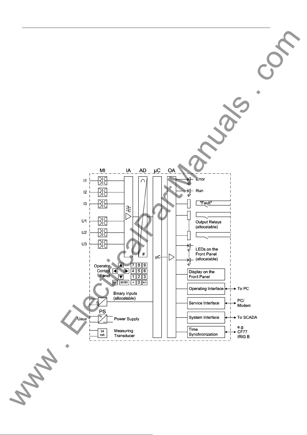
The SIPROTEC® 4 7ST6, Numerical Overhead Contact Line Protection for AC
Traction Power Supply, is equipped with a powerful 32-bit microprocessor. All tasks
are processed numerically, from acquisition of measured values up to commands to
the circuit breakers. Figure 1-1 shows the basic structure of the 7ST63.
There are two different device versions, 7ST6 1 and 7ST63, which dif fer ma inly by the
size of their housing and the number of available inputs and outputs.
7ST61 housing size 1/2 * 19“ with 4-line display, 12 BI and 22 or 27 BO
7ST63 housing size 1/1 * 19“ with graphic display, control keys, 38 BI and 36 BO
Analog Inputs The measuring inputs (MI) convert the currents and voltages coming from the trans-
formers and adapt them to the level appropriate for the internal processing of the
device. Depending on the version, the device is equipped with up to 3 current and
voltage inputs.
Figure 1-1 Hardware structure of the numerical overhead contact line protection 7ST63
The analog values are transferred to the IA input amplifier group.
16
E50417-G1176-C251-A3
7ST6 Manual

1.1 Overall Operation
www . ElectricalPartManuals . com
The IA input amplifier group allows high impedance connection for analog input values
and contains filters optimized with regard to bandwid th and processing speed for measured value processing.
In the analog/digital converter unit, the analog input value s are sampled, digitized and
supplied to the microcomputer system.
Microcomputer System
Binary Inputs and Outputs
Front Elements Optical indicators (LEDs) and a front LC display provide information on the function of
Apart from processing the measured values, the microcomputer system µC also executes the actual protection and control functions. They especially consist of:
• Filtering and conditioning of the measured values
• Continuous monitoring of the measured values
• Monitoring of the pickup conditions for the individual protective functions
• Scanning of limit values and time sequences
• Control of signals for logic functions
• Deciding on trip and close commands
• Storage of indications, fault data and fault values for fault analysis purposes
• Management of the operating system and its functions, e.g. data memory , real-time
clock, communication, interfaces, etc.
The information is provided via output amplifier OA.
Binary inputs and outputs from and to th e computer system are routed via the I/O
modules (inputs and outputs). The compu ter system obt ains the information fro m the
system (e.g remote resetting) or the external equipment (e.g. blocking commands).
Additional outputs are mainly commands that ar e issued to the switch ing devices and
indications for remote signalling of events and states.
the device and indicate events, states and measured values.
Integrated control and numeric keys in conjunction with the LCD facilitate local inter-
action with the local device. All information of the device can be accessed using the
integrated control and numeric keys. Th e information includes protective and control
settings, operating and fault indications, measured values and settings (see also
Chapter 2 and SIPROTEC
Devices with control functions also allow station control on the front panel.
Serial Interfaces Via the serial interface
using the operating program DIGSI
all device functions.
The service
using DIGSI
the devices and the PC or in case of an operation via modem.
All device data can be transmitted to a cent ral evaluating unit or control center through
the serial system (SCADA) interface
physical transmission modes and different protocols to suit the particular application.
An additional interface is designed for time synchronization
means of external synchronization sources.
Further communication protocols can be implemented via additional interface modules.
interface can also be used for communication with a personal computer
®
. This interface is particularly well suited in case of hard wiring between
®
4 System Description, Order No. E50417-H1176-C151).
in the front panel the communica tion with a personal computer
®
is possible. This ensures convenient operation of
. This interface may be provided with various
of the internal clock by
7ST6 Manual
E50417-G1176-C251-A3
17

1 Introduction
www . ElectricalPartManuals . com
Power Supply These described functional units are supplied by a power supply PS with the neces-
sary power in the different voltage levels. Brief supply voltage dips which may occur
on short circuits in the auxiliary voltage supply of the power system are usually bridged
by a capacitor (see also Technical Data, Chapter 4).
18
E50417-G1176-C251-A3
7ST6 Manual

1.2 Application Scope
www . ElectricalPartManuals . com
The SIPROTEC® 4 7ST6, Numerical Overhead Contact Line Protection for AC
Traction Power Supp ly, is a se lective and fast protection device for ove rhead cont a ct
lines with single- and multi-ended infeeds.
The device incorporates the functions which are normally required for the protection
of an overhead contact line section and is therefore capable of universal application.
1.2 Application Scope
Protective Elements
The basic function of the device is the recognition of the dista nce to the fa ult with distance protection measurement. It is supplemented by a range of other protection fu nctions:
When switching to a faulted line section, an undelayed trip signal can be output.
In the event of a failure of the measured voltages due to a fault in the secondary cir-
cuits (e.g. trip of the voltage transformer mcb or a fuse) the device can automatically
revert to an emergency operation with an integrated time overcurrent protection
(emergency time overcurrent protection), until the measured voltage again becomes
available. There is an additional 3-stage definite/inverse time overcurrent protection
operating in parallel to, and independe nt of, the distance protection. This time overcurrent protection has three current-independent stage s and one current-dependent
stage. For inverse time overcurrent protection, several curves of different standards
are provided. The stages can be combined in any way. Moreover, a high-speed overcurrent protection function with a tripping time of less than 2 ms is integrated.
Most short-circuit functions work in conjunction with an integrated automatic reclose
function which is designed for 8 reclosing attempts. Before reclosure, the validity of
the reclosure can be checked by voltage and/ or synchronism check by the device (this
can be ordered as an option).
Beside the short-circuit protection functions described above, the device offers additional protection functions such as multip le -stage over voltage and un d er vo ltage protection, circuit breaker failure protection, and thermal overload protection, which protects the overhead contact line from excessive heating due to overloads. The fault
locator supports fast location of the fault after a short-circuit. The inrush restraint
feature is used for a clear distinction between operating and fault conditions during
switching operations. The defrosting protection feature provides high-sensitivity detection of short-circuits during defrosting of the overhead contact line.
Control Functions Depending on the ordered variant the device provides control functions which can be
accomplished for activating and deactivating switchgear via the integrated operator
panel, the system interface, binary input s and a personal compu ter with the operating
software DIGSI
via auxiliary contacts connected to binary inputs. The present status (or position) of
the primary equipment can be displayed on th e device , an d used for interlocking or
plausibility monitoring. The number of the primary equipment to be switched is limited
by the binary inputs and outputs available in the device or the binary inputs and
outputs allocated for the switch position indications. Depending on the primary equipment being controlled, one binary input (single point indication) or two bi nary inputs
(double point indication) may be used for this process. The capability of switching
primary equipment can be restricted by a setting associated with switching authority
(Remote or Local), and by the operating mode (interlocked/non-interl ocked, with or
without password request). Processing of interlocking conditions for switching (e.g.
switching error protection) can be established with the aid of int eg ra te d , use r-c o nf igurable logic functions.
7ST6 Manual
E50417-G1176-C251-A3
®
. The status of the primary equipment can be transmitted to the device
19

1 Introduction
www . ElectricalPartManuals . com
Indications and Measured Values; Fault Recording
Communication Serial interfaces are available for the communication with operating, control and
The operational indications provide information about cond itions in the power system
and the device itself. Measurement quantities and resulting computed values can be
displayed locally and communicated via the serial interfaces.
Device indications can be assigned to a number of LEDs on the front cover (allocatable), can be externally processed via output contacts (alloca table), linked with userdefinable logic functions and/or issued via serial interfaces.
During a fault (system fault) important events an d changes in co nditions are saved in
fault logs (Event Log or Trip Log). Instantaneous fault values are also saved in the
device and may be analysed subsequently.
memory systems.
20
E50417-G1176-C251-A3
7ST6 Manual

1.3 Characteristics
www . ElectricalPartManuals . com
1.3 Characteristics
General Characteristics
Distance Protection • Distance protection function with three zones (Z1, Z2, and Z3), high measuring ac-
• Powerful 32-bit microprocessor system
• Complete digital processing of measured values and con trol, from th e sampling o f
the analog input values up to the closing and tripping comman ds to the circuit
breakers
• Complete galvanic and reliable separation between internal processing circuits
from the measurement, control, and power supply circuit s by analog input tran sducers, binary inputs and outputs and the DC/DC or AC voltage converters
• Complete scope of functions which are normally req uired for the protection of a line
feeder
• Simple device operation using the integrated operator panel or a connected personal computer with operator guidance
• Storage of fault indications as well as instantaneous values for fault recording
curacy and the ability to adapt to the given system conditions
• Impedance curve with “combined” or “polygonal” tripping characteristic can be selected
• for the direction characteristic settable to “for ward “, “n on -d ir ect i on a l“, ”fo r war d ex tended“, “reverse“;
• Combined tripping characteristic with separate setting of reach (absolute impedance value Z), angle and load limitation (resistance R);
Time Overcurrent Protection
High Current Switch-onto-Fault Protection (optional)
Emergency Time Overcurrent Protection
• Adaptation to different switching states of the overhead contact line during operation is ensured by the changeover function of the impedance stages
• Instantaneous tripping when switching onto a fault;
• Inrush restraint possible for zone Z2 and higher;
• Full non-directional time overcurrent protection function (definite/inverse time) with
three stages (very high set current stage I>>>, high set current stage I>>, overcurrent stage I>)
• Instantaneous tripping when switching onto a fault;
• Inrush restraint feature to prevent overfunctioning during the inru sh phase
• Very short tripping times (<2 ms) when the tripping threshold is exceeded
• Faults can be tripped as early as the first zero crossing of the current (in 16.7 Hz
systems)
• Single-stage emergency time overcurrent protection (I> time overcurrent protection)
• Instantaneous tripping when switching onto a fault;
• Inrush restraint feature to prevent overfunctioning during the inru sh phase
• Backup protection in case of measured voltage failure;
7ST6 Manual
E50417-G1176-C251-A3
21

1 Introduction
www . ElectricalPartManuals . com
Voltage Protection (optional)
Thermal Overload Protection
Circuit Breaker Failure Protection (optional)
Defrosting Protection
Inrush Restraint (optional)
• Two-stage overvoltage and undervoltage detection
• Two overvoltage stages for the overhead contact line ( U>>, U> )
• Two undervoltage stages for the overhead contact line (U<<, U<)
• Determination of the overhead contact line temperature by creating a thermal profile
of the object to be protected
• Adjustable thermal alarm level
• 2 independent time stages
• Tripping by 2 independent, adjustable monitoring time stages
• Start by trip command of every internal protection function
• External start possible
• Differential protection for defrosting current with configurable characteristic
• Back-up protection with two-stage definite-time overcurrent protection
• Distinction between operating and fault condition by harmonics analysis
• Possibility of blocking selected protection functions
Automatic Reclosure Function (optional)
Synchronism and Voltage Check (optional)
Fault Locator (optional)
Trip Load (optional) • Detection and summation of interrupted currents
• Single or multiple reclosure (up to 8 reclosure attempts)
• With separate idle and operating times for the first 4 reclosure attempts
• Synchronism check before reclosing
• Verification of the synchronous conditions before energisation;
• Fast measuring of voltage dif ference U
frequency difference f
• Alternatively, check of the de-energized state before energisation;
• Switching possible for asynchronous system conditions with prediction of the synchronization time
• Settable minimum and maximum voltage
• Verification of the synchronous conditions or de-energized state also possible
before dispositive closing of the circuit breaker, with separate limit values;
• Start by tripping command or dropout of the pickup, even with high-current switchonto-fault protection
• Fault location output in Ω, kilometers or miles and % of line length;
Diff
of the phase angle difference ϕ
Diff
Diff
and
• Monitoring with It function (optional)
• Alarm output when limit is exceeded
22
E50417-G1176-C251-A3
7ST6 Manual

1.3 Characteristics
www . ElectricalPartManuals . com
Trip Circuit Supervision
User Defined Functions (optional)
Breaker Control • Switchgear can be activated and de-activated manually via local control keys
Monitoring Functions
• Integrated trip circuit supervision
• Freely programmable combination of internal and external signals for the implementation of user-defined logic functions
• All common logic functions
• Delays and limit-value inquiries
(7ST63), the programmable function keys, via the system interface (e.g. SITRAS
SCS), or via the operating interface (using a personal computer and the DIGSI
software);
• Feedback on switching states via the circuit breaker auxiliary contacts (for commands with feedback)
• Plausibility monitoring of the circuit breaker positions and interlocking conditions for
switching.
• Availability of the device is greatly increased because of self-monitoring of the internal measurement circuits, power supply, hardware, and software
• Monitoring of overhead contact line voltage (Fuse Failure Monitoring);
®
®
• Monitoring of ambient temperature sensing
• Trip circuit supervision possible;
• Display of operating impedances and direction
Further Functions • Battery buffered real time clock, which may be synchronized via a synchronization
signal (e.g. DCF77, IRIG B via satellite receiver), binary input or system interface
• Continuous calculation and display of measured quantities on the front display
• Fault event memory (trip log) for the last 8 network faults (faults in the power system), with real time stamps
• Fault recording and data transfer for fault recording for a maximum time range of
15 s
• Statistics: Counter with the trip commands issued by the device, as well as recording of the current-time integrals, the fault curr en t da ta and accumu la tio n of th e interrupted fault currents
• Communication with control center possible via serial interfaces (depending on the
ordering variant), optionally via data line, modem or fibre optics;
• Commissioning aids such as connection and direction checks as well as circuit
breaker test functions
■
7ST6 Manual
E50417-G1176-C251-A3
23

1 Introduction
www . ElectricalPartManuals . com
24
E50417-G1176-C251-A3
7ST6 Manual

Functions 2
www . ElectricalPartManuals . com
This chapter describes the individual functions of the SIPROTEC 4 device 7ST6. It
shows the setting possibilities for each function in maximum configuration. Guidelines
for establishing setting values and, where required, formulae are given.
Additionally, on the basis of the following information, it may be defined which functions are to be used.
2.1 General 26
2.2 Distance Protection 47
2.3 Overcurrent Protection 76
2.4 High-Speed Overcurrent Protection 84
2.5 Emergency Overcurrent Protection 87
2.6 Overvoltage and Undervoltage Protection 90
2.7 Thermal Overload Protection 94
2.8 Circuit Breaker Failure Protection 103
2.9 Trip Supervision 109
2.10 Defrosting Protection 111
2.11 InRush Restraint 120
2.12 Automatic Reclosure Function 124
2.13 Synchronism and Voltage Check 142
2.14 Fault Locator 152
2.15 It Function (current-time integral) 156
2.16 Monitoring Function 166
2.17 Trip Circuit Supervision 170
2.18 Protection Function Control 174
2.19 Auxiliary Functions 186
2.20 Command Processing 194
2.21 Use in auto-transformer systems 205
257ST6 Manual
E50417-G1176-C251-A3
2 Functions
www . ElectricalPartManuals . com
2.1 General
A few seconds after the device is switched on, the initial display appears in the LCD.
Depending on the device version either measured values (four-line display, device
type 7ST61) or a single-phase switching diagram of the feeder st atus (graphic display ,
device type 7ST63) is displayed in the 7ST6.
Configuration of the device functions are made via the DIGSI
The procedure is described in det ail in the SIPROTEC
No. E50417-H1176-C151. Entry of password No. 7 (for setting modification) is required to modify configuration settings. Without the password, the settings may be
read, but may not be modified and transmitted to the device.
The function parameters, i.e. settings of function options, threshold values, etc., can
be entered via the keypad and display on the front of the device, or by means of a personal computer connected to the front or service interface of the device utilising the
DIGSI
2.1.1 Functional Scope
®
®
®
software package. The level 5 password (individual parameters) is required.
software from your PC.
4 System Description, Order
2.1.1.1 Configuration of the Functional Scope
The 7ST6 relay contains a series of protective and additional function s. The hardware
and firmware provided is designed for this scope of fun ctio ns . In ad dit i on the
command functions can be matched to the system conditions. Individual functions can
be activated or deactivated during the configuration procedure. The interaction of
functions may also be modified.
The available protective and additional functions must be configured as Enabled or
Disabled. For some functions a choice between several alternatives is possible, as
described below.
Functions configured as Disabled are not processed by the 7ST6. There are no indications, and corresponding settings (functions, limit values) ar e not displayed during
setting.
Note
The functions and default settings available depen d on the order variant of the device.
Enabling/disabling of Functions
The protection functions can partly be enabled and dis abl ed via different so ur ce s,
namely:
• Parameterisation (Para)
• Binary Input (BI)
• System Interface (SI)
A function is disabled as soon as it is switched off by one of th e three sources. In order
to enable a function again, it must be switched on by all sources by which it had been
switched off.
The on or off state via binary input remains after a restart. After an initial start this state
is pre-defined as "on".
26
E50417-G1176-C251-A3
7ST6 Manual
2.1 General
www . ElectricalPartManuals . com
The following table presents an overview of the activation or blocking of functions.
Details are set out in the respective function description.
ON/OFF Blocking
Function BI SI Para BI SI Para
Distance Protection x - x x - High-Speed Overcurrent Pro-
tection
Overcurrent Protection x - x - - Emergency Overcurrent Pro-
tection
Voltage Protection - - x - - Thermal Overload Protection x - x - - Defrosting Protection x x x x x x
Inrush Restraint - - - - - Fault locator - - - - - Breaker Failure Protection x - x - - Trip circuit supervision - - x - - IT Function x - x - - Synchro-check x - x x - Automatic Reclosure Function x x x x - -
x-x---
x-x---
2.1.1.2 Setting Notes
Configuration of Fu n c ti on al Sc op e
Special Characteristics
Configuration settings can be entered by using a PC and th e software program DIGSI
and transferred via the operating interface of the device or via the service interface on
the rear. Operation using DIGSI
tion, order no. E50417-H1176-C151.
Entry of password No. 7 (for setting modification) is required to modify configuration
settings. Without the password, the settings may be read, but may not be modified and
transmitted to the device.
The functional scope with the available options is set in the Functional Scope di alog
box to match plant requirements.
Most settings are self-explaining. The special cases are described below.
If use of the setting group changeover function is desired, address 103 Grp Chge
OPTION should be set to Enabled. In this case, up to four different groups of settings
may be changed quickly and easily during device operation (see also Subsection
2.1.4). Only one setting group may be selected and used if the setting is Disabled.
The impedance characteristic valid for distance protection is selected under address
113 DISTANCE CURVE. You can choose between distance protection with combined
tripping characteristic and distance protection with polygonal tripping characteristic
(see Section 2.2).
®
is described in the SIPROTEC®4 System Descrip-
®
The available protection and supplement ary functions can be configured as Enabled
or Disabled.
When ordering devices, please note that the basic device version does not offer the
full scope of functions. The table below shows which functions are provided in the
basic device version, and which must be ordered separately if required:
7ST6 Manual
E50417-G1176-C251-A3
27
2 Functions
www . ElectricalPartManuals . com
Function Provided in the Basic
Version
Distance Protection X
Time Overcurrent Protection X
Emergency Overcurrent Protection X
Thermal Overload Protection X
Ambient Temperature Sensing X
Trip Circuit Supervision X
Defrosting Protection X
Current-time Integral X
High-Speed Overcurrent Protection X
Inrush Restraint X
Automatic Reclosure X
Synchro-check X
Circuit Breaker Failure Protection X
Voltage Protection X
Fault Locator X
Not Provided in the Basic
Version
28
E50417-G1176-C251-A3
7ST6 Manual
2.1.1.3 Settings
www . ElectricalPartManuals . com
Addr. Par ameter Setting Options Default Setting Comments
103 Grp Chge OPTION Disabled
Enabled
104 OSC. FAULT REC. Disabled
Enabled
113 DISTANCE CURVE Quadrilateral
Combined
122 InrushRestraint Disabled
Enabled
124 FCT HS O/C Disabled
Enabled
126 Back-Up O/C Disabled
Enabled
127 FCT Emerg. O/C Disabled
Enabled
133 Auto Reclose Disabled
Enabled
135 Synchro-Check Disabled
Enabled
137 O/U VOLTAGE Disabled
Enabled
138 Fault Locator Disabled
Enabled
139 BREAKER FAILURE Disabled
Enabled
140 Trip Cir. Sup. Disabled
Enabled
141 FCT It-Calc. Disabled
Start by Aux
Start by TRIP
142 Therm.Overload Disabled
Enabled
143 Temp.Sens Disabled
-30 to +55 °C
-55 to +55 °C
144 FCT DEFROSTING Disabled
Enabled
Enabled Setting Group Change Option
Enabled O scillographic Fault Records
Combined Distance Curve
Enabled 2nd Harmonic Inrush Restraint
Enabled I nstantan. High-Speed O/C Pro-
tection
Enabled B ackup overcurrent
Enabled Emerg ency Overcurrent Protec-
tion
Enabled Auto-Reclose Function
Enabled S ynchronism and Voltage Check
Enabled Under / Overvoltage Protection
Enabled Fault Locator
Enabled Breaker Failure Protection
Disabled Trip Circuit Supervision
Start by TRIP It Function (ampere-seconds)
Disabled Thermal Overload Protection
Disabled Ambient Temperature Sensi ng
Disabled Defrosting Protection Function
2.1 General
7ST6 Manual
E50417-G1176-C251-A3
29
2 Functions
www . ElectricalPartManuals . com
2.1.2 Device
The device requires some general information. This may be, for example, the type of
indication to be issued in the event a power system fault occurs.
2.1.2.1 Trip Dependent Indications
The recording of indications masked to local LEDs, and the maintenance of spont ane-
ous indications, can be made dependent on whether the device has issued a trip
signal. This information is then not output if during a syste m disturbance one o r more
protection functions have picked up, but no tripping by the 7ST6 resulted because the
fault was cleared by a different device (e.g. on another line). These indications are
then limited to faults in the line to be protected.
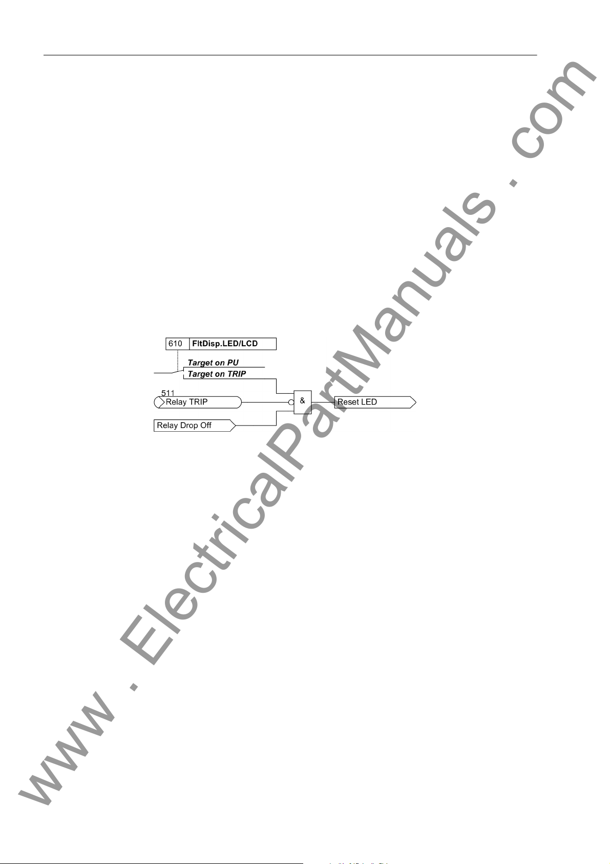
The figure below illustrates the creation of the reset command for stored indications.
When the relay drops out, stati onary conditions (fault display Target on PU / Target on
TRIP; Trip / No Trip) decide whethe r the new fault will be stored or reset.
Figure 2-1 Creation of the reset command for the memory of LED and LCD displays
2.1.2.2 Spontaneous Indications on the Display
Y ou can determine wh ether or not the most import ant data of a fault event is displayed
automatically after the fault has occurred (see also „Fa ult indications“ in Section 2.19.1
„Auxiliary Functions“).
2.1.2.3 Setting Notes
Fault Indications Pickup of a new protective function generally turns off any previously lit LEDs, so that
only the latest fault is displayed at any time. It can be selected whether the stored LED
displays and the spontaneous indications on the display a ppear upon renewed pickup,
or only after a renewed trip signal is issued. In order to enter the desired type of display, select the submenu Device in the SETTINGS menu. At address 610
FltDisp.LED/LCD the two alternatives Target on PU and Target on TRIP („No
trip - no flag“) are offered.
For devices with graphical display use parameter 615 Spont. FltDisp. to specify
whether or not a spontaneous indication will appear automatically on the display (YES)
or not (NO). For devices with text display such indications will appear after a system
fault by any means.
You can set at address 620 T Backlight on how long the display backlight will
remain on after an entry on the integrated keypad.
30
E50417-G1176-C251-A3
7ST6 Manual
 Loading...