

Page 1

Preface
www . ElectricalPartManuals . com
Table of Contents
Introduction 1
SIPROTEC
Distributed Busbar/ Breaker
Failure Protection
7SS522 V4.6
7SS523 V3.3
7SS525 V3.3
Manual
Design and Connection System 2
Getting Started 3
Configuration 4
Functions 5
Control During Operation 6
Installation and Commissioning 7
Maintenance and Repair 8
Technical Data 9
C53000-G1176-C182-3
Appendix A
References
Index
Page 2

Exclusion of Liability
-
-
www . ElectricalPartManuals . com
We have checked the contents of this publication and every effort has been
made to ensure that the descriptions of both hardware and software are as
accurate as possible. However, deviations from the description cannot be
completely ruled out, so that no liability can be accepted for any errors or
omissions contained in the information given.
The data in this manual are checked regularly and the necessary corrections
are included in subsequent editions. We are grateful for any improvements
that you care to suggest.
Subject to technical modifications.
Document Release 4.62.00
Edition 09.2007
Copyright
Copyright © Siemens AG 2007 All Rights Reserved
Dissemination or reproduction of this document, or evaluation and communication of its contents, is not authorized except wh ere expr essly p ermitted .
Violations are liable for damages. All rights reserved, parti cularly for the pur
poses of patent application or trademark registration.
Registered Trademarks
®
is a registered trademark of SIEMENS AG. Other designations in
DIGSI
this manual may be trademarks that if used by third parties for their own pur
poses may violate the rights of the owner.
Siemens AG Order-No. C53000-G1176-C182-3
Page 3

Preface
www . ElectricalPartManuals . com
Aim of this Manual This manual describes the functions, operation, installation, and commissioning of the
complete SIPROTEC 7SS52 V4 distributed busbar and breaker failure protection system. In particular, you will find:
• Information on configuration of the system → Chapter 4, page 45
• Description of the system functions and their setting op tions → Chapter 5, page 91
• Information on control during operation → Chapter 6, page 209
• Information on installation and commission in g → Chapter 7, page 255
• Overview of technical data → Chapter 9, page 311
• and a compilation of the most important information for the exper ienced user
→ Chapter A.1, page 336
The SIPROTEC 4 System Description /1/ deals in a general way with the management, configuration, parameterization, operation, installation and commissioning of a
SIPROTEC 4 system.
Target audience Protection engineers, commissioners, persons who are involved in setting, testing and
maintenance of protection, automation, and control devices, as well as operation personnel in electrical plants and power stations.
Scope of validity of
this manual
This manual is valid for the complete SIPROTEC 7SS52 V4 distributed busbar and
breaker failure protection system, firmware version 4.6. The system comprises the
central unit 7SS522 V4.6 and the bay units 7SS523 V3.3 and 7SS525 V3.3. The complete system will be referred to in the manual as 7SS52 V4.
Indication of Conformity
This product complies with the directive of the Council of the Eur opean Comm unities
on the approximation of the laws of the Member States relating to electromagnetic
compatibility (EMC Council Directive 89/336/EEC) and concerning electrical equipment for use within specified voltage limits (Low-voltage directive 73/23 EEC).
This conformity has been proved by tests performed according to Article 10 of the
Council Directive in agreement with the generic standards EN 61000-6-2 and EN
61000-6-4 (for EMC directive) and with the standard EN 60255-6 (for Low Voltage Directive) by Siemens AG.
The device is designed and manufactured for application in industrial environment.
The product conforms with the international standar ds of IEC 60255 and the Ger man
standard VDE 0435.
iii7SS52 V4 Manual
C53000-G1176-C182-3
Page 4

Preface
www . ElectricalPartManuals . com
Additional support For any questions concerning your SIPROTEC system, please contact your Siemens
representative.
Training courses Individual course offers may be found in our T raining Cat alog, or questions can b e di-
rected to our training center in Nuremberg.
Instructions and
Warnings
The warnings and notes contained in this manual serve for your own safety and for an
appropriate lifetime of the device. Please obser ve the m!
The following terms and definitions are used:
DANGER
indicates that death, severe personal injury or substantial property damage will result
if proper precautions are not taken.
Warning
indicates that death, severe personal injury or substantial property damage can result
if proper precautions are not taken.
Caution
indicates that minor personal injury or property damage can result if proper precautions are not taken. This is especially valid for damage on or in the device itself and
consequential damage thereof.
Note
indicates information about the device or respective part of the instruction manual
which is essential to highlight.
Warning!
Hazardous voltages are present in this electrical equipment during operation. Non–
observance of the safety rules can result in severe personal injury or property damage.
Only qualified personnel shall work on and around this equipment afte r becoming thoroughly familiar with all warnings and safety notices of this manual as well as with the
applicable safety regulations.
The successful and safe operation of this device is dependent on proper handlin g, installation, operation, and maintenance by qualified personnel under observance of all
warnings and hints contained in this manual.
In particular the general erection and safety regulations (e.g. IEC, DIN, VDE, EN or
other national and international standards) regarding the corr ect u se of hoisting gear
must be observed. Non–observance can r esult in death, personal injury or substantial
property damage.
iv
7SS52 V4 Manual
C53000-G1176-C182-3
Page 5

Preface
www . ElectricalPartManuals . com
QUALIFIED PERSONNEL
For the purpose of this instruction manual and product labels, a qualified person is one
who is familiar with the installation, construction and operation of the equipment and
the hazards involved. In addition, he or she has the following qualifications:
• Is trained and authorized to energize, de-energize, clear, ground and tag circuits
and equipment in accordance with established safety practices.
• Is trained in the proper care and use of protective equipment in accordance with established safety practices.
• Is trained in rendering first aid.
Typographic
and symbol
conventions
The following text formats are used when literal information from the device or to the
device appear in the text flow:
Parameter names, i.e. designators of configuration or function parameters, which
may appear word-for-word in the display of the device or on the screen of a personal
computer (with DIGSI), are marked in bold letters of a monospace type style.
Parameter options, i.e. possible settings of text parameters, which may appear
word-for-word in the display of the device or on the screen of a personal computer
(with DIGSI), are written in italic style, additionally. This applies also for options in
menus.
“Annunciations”, i.e. designators for information, which may be output by the relay
or required from other devices or from the switch gear, are marked in a monospace
type style in quotes.
Deviations may be permitted in drawings when the type of designator can be o bviously
derived from the illustration.
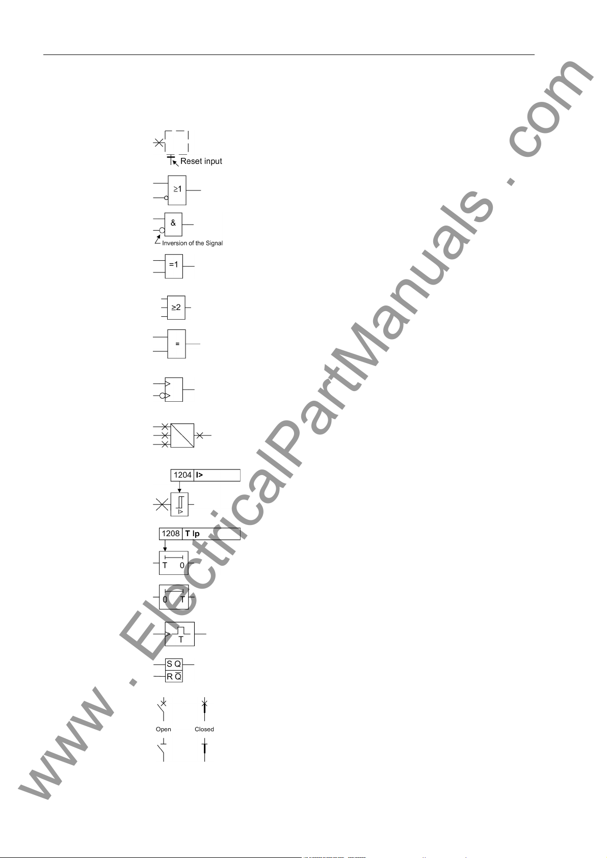
The following symbols are used in drawings:
Device-internal logical input signal
Device-internal logical output signal
Internal input signal of an analog quantity
External binary input signal with number (binary input,
input indication)
External binary output signal with number (device indication)
Example of a parameter switch designated with the
address and the possible settings
7SS52 V4 Manual
C53000-G1176-C182-3
v
Page 6
Preface
www . ElectricalPartManuals . com
Besides these, graphical symbols are used according to IEC 60 617–12 and
IEC 60 617–13 or symbols derived from these standards. The most frequen t symbols
are the following:
Input signal of an analogue quantity
OR-combination of input values
AND-combination of input values
Exclusive–OR gate: output is active, if only one of the
inputs is active
2-of-3-combination of input values
Coincidence: output is active if both inputs are active
or inactive at the same time
Dynamic input signals (edge–triggered) above with
positive, below with negative edge
Formation of one analogue output signal from a
number of analogue input signals
Limit value stage with parameter addr ess and parameter name
Timer (pickup delay T adjustable) with parameter
address and parameter name
Timer (dropout delay T, non-adjustable)
Edge-controlled time stage with effective time T
Static memory (RS-flipflop) with setting input (S),
resetting input (R), output (Q) and inverted output (Q)
Circuit breaker (open and closed)
Isolator (open and closed)
vi
7SS52 V4 Manual
C53000-G1176-C182-3
Page 7

Table of Contents
www . ElectricalPartManuals . com
1 Introduction.......................................................................................................................................... 1
1.1 Overall Operation ................................................................................................................... 2
1.2 Applications............................................................................................................................ 4
1.3 Features ................................................................................................................................. 5
2 Design and Connection System....................................................................................................... 13
2.0 General................................................................................................................................. 14
2.1 Central Unit .......................................................................................................................... 15
2.1.1 Front View ............................................................................................................................ 15
2.1.2 Modules and Submodules.................................................................................................... 16
2.1.3 Design .................................................................................................................................. 17
2.2 Bay Unit................................................................................................................................ 18
2.2.1 Front View ............................................................................................................................ 18
2.2.2 Modules and Submodules.................................................................................................... 19
2.2.3 Design .................................................................................................................................. 21
2.2.3.1 Panel Surface Mounting....................................................................................................... 21
2.2.3.2 Panel Flush Mounting or Cubicle Mounting.......................................................................... 21
2.3 Connection Method .............................................................................................................. 22
2.3.1 Location of Device Connections........................................................................................... 22
2.3.2 Device Connections.............................................................................................................. 25
2.3.2.1 Screw-Type Terminals.......................................................................................................... 26
2.3.2.2 Double Leaf-Spring-Crimp Contacts..................................................................................... 26
2.3.2.3 D-SUB Female Connectors........... ... .... ... ... ... .... ... ... ... .... ... ... ... ....... ... ... ... .... ... ... ... ... .... ... ... .. .27
2.3.2.4 Fiber-Optic Cable Connections ............................................................................................27
2.3.2.5 EN100 module Ethernet (IEC 61850)................................................................................... 28
3 Getting Started...................... ... ... ... .... ...................................... .... ...................................................... 29
3.1 Unpacking and Repacking.................................................................................................... 30
3.2 Checking the Rated Data ........................................ ... .... ... ... ... ... ....................................... ... 30
3.3 Matching the Control Voltage for the Binary Inputs and
Inserting the Buffer Battery................................................................................................... 31
3.4 Electrical Checks.................................................................................................................. 38
3.5 Setting up the Communication between the Central Unit
vii7SS52 V4 Manual
C53000-G1176-C182-3
Page 8

Table of Contents
www . ElectricalPartManuals . com
and the Bay Unit............................. ... ....................................... ... ......................................... 39
3.6 Operation of SIPROTEC Devices from the Operator Panel ................................................. 40
3.6.1 User Interface....................... ... ... .... ... ....................................... ... ......................................... 40
3.6.2 Navigating the Operating Tree of the Display....................................................................... 40
3.6.3 Setting Addresses in the Bay Unit ........................................................................................ 41
3.6.4 Adjusting the Display Contrast.............................................................................................. 43
3.7 Storage................................................................................................................................. 44
4 Configuration ..................................................................................................................................... 45
4.1 Creating a Project................................................................................................................. 46
4.2 Inserting Central Unit / Bay Units.......................................................................................... 47
4.3 Plant Configuration............................ ... ....................................... ... ...................................... 49
4.3.1 How to Proceed.................................................................................................................... 49
4.3.2 Starting the Plant Configuration .. .... ... ... ... ... .... ...................................... ................................ 50
4.3.3 Drawing Busbars .................................... ... .... ... ... ... .... ...................................... ................... 52
4.3.4 Defining Bays........................................................................................................................ 54
4.3.5 Inserting Dynamic Elements....... ....................................... ....................................... ... .........56
4.3.6 Connecting Dynamic Elements to the Busbars .................................................................... 58
4.3.6.1 Inserting Lines ......................................... ....................................... ...................................... 58
4.3.6.2 Inserting a Connection................................ .... ... ... ....................................... ......................... 59
4.3.7 Normalized Current...............................................................................................................60
4.3.8 Inserting Static Text....... .... ...................................... .... ...................................... ................... 61
4.3.9 Creating and Inserting Typicals...................... ... ... ... .... ...................................... .... ...............62
4.3.10 Saving the Substation Chart................................................................................................. 62
4.4 Configuration Notes....... ....................................... ....................................... ... ...................... 63
4.5 Assigning Bay Units.............................................................................................................. 71
4.6 Marshalling ........................................................................................................................... 73
4.6.1 Marshalling Information Items of the Central Unit................................................................. 73
4.6.1.1 Allocable Information............ ... ....................................... ... ....................................... ............ 73
4.6.1.2 Marshalling ........................................................................................................................... 74
4.6.2 Marshalling Bay Unit Information.......................................................................................... 76
4.6.2.1 Allocable Information............ ... ....................................... ... ....................................... ............ 76
4.6.2.2 Marshalling ........................................................................................................................... 77
4.7 Settings................................................................................................................................. 80
4.7.1 Serial Ports.................... .... ... ... ... .... ... ... ....................................... ......................................... 81
4.7.2 Date/Clock Management......................................................................................................85
4.8 Concluding the Configuration ............................................................................................... 89
viii
7SS52 V4 Manual
C53000-G1176-C182-3
Page 9

Table of Contents
www . ElectricalPartManuals . com
5 Functions............................................................................................................................................ 91
5.1 Busbar Protection................................................................................................................. 92
5.1.1 Mode of operation ................................................................................................................ 92
5.1.1.1 Basic Principle............ ....................................... ...................................... .... ......................... 92
5.1.1.2 Algorithm with Instantaneous Values ................................................................................... 94
5.1.1.3 Separate Evaluation of Half-Cycles...................................................................................... 96
5.1.1.4 Evaluation of the Initial Values ............................................................................................. 99
5.1.1.5 Algorithm with Filtered Values............................................................................................ 100
5.1.1.6 Summary of the Measuring Method ................................................................................... 100
5.1.2 Isolator Replica. ... .... ... ....................................... ...................................... .... ....................... 101
5.1.3 Bus Coupler Variants.......................................................................................................... 103
5.1.3.1 Bus Couplers with One Current Transformer..................................................................... 103
5.1.3.2 Bus Couplers with Two Current Transformers ................................................................... 104
5.1.3.3 Bus Couplers without Circuit Breaker................................................................................. 104
5.1.3.4 Bus Couplers with more than 5 Isolators............................................................................ 104
5.1.3.5 Combi-Coupler ................................................................................................................... 104
5.1.3.6 Transfer Busbars..... ... ... ... .... ... ... ....................................... ...................................... ........... 105
5.1.3.7 Transfer Busbar With Inside Transformers................................. ....... ... ... .... ... ... ... ... .... ... ... . 107
5.1.3.8 Special Cases of Transfer Busbar Operation.......... ... .... ... ... ... ... .... ... ... ... .... ... ... ... ... .... ... ... . 107
5.1.4 Setting Notes...................................................................................................................... 108
5.1.5 Settings for the Central Unit ............................................................................................... 111
5.2 Check Zone........................................................................................................................ 112
5.2.1 Mode of operation .............................................................................................................. 112
5.2.2 Setting Notes...................................................................................................................... 113
5.2.3 Settings for the Central Unit ............................................................................................... 113
5.3 Circuit Breaker Failure Protection....................................................................................... 114
5.3.1 Characteristics for the Circuit Breaker Failure Protection.................................. ...... .... ... ... . 114
5.3.2 Setting Notes...................................................................................................................... 115
5.3.3 Settings for the Central Unit ............................................................................................... 116
5.3.4 List of Information from the Central Unit..... ... .... ... ... ... .... ...................................... .............. 116
5.3.5 Bay-Specific Functions (BU)............................................................................................... 117
5.3.5.1 Triggering and Releasing the Breaker Failure Protection................................................... 117
5.3.5.2 Circuit Breaker Failure Protection during a Feeder Short-Circuit...... ... ... .... ...... ... ... .... ... ... . 119
5.3.5.3 Circuit Breaker Failure Protection for Busbar Faults.......................................................... 126
5.3.5.4 Failure of the Bus Coupler Circuit Breaker......................................................................... 127
5.3.5.5 Circuit Breaker Not Ready.................................................................................................. 127
5.3.6 Setting Notes...................................................................................................................... 128
5.3.7 Settings for the Central Unit ............................................................................................... 132
5.3.8 List of Information from the Central Unit..... ... .... ... ... ... .... ...................................... .............. 133
5.3.9 List of Information from the Bay Unit................................. ...................................... ........... 134
7SS52 V4 Manual
C53000-G1176-C182-3
ix
Page 10

Table of Contents
www . ElectricalPartManuals . com
5.4 End Fault Protection........................................................................................................... 135
5.4.1 End Fault Protection in the Feeder..................................................................................... 135
5.4.2 Protection with fault in the ”Dead Zone” of the Bus Coupler........................... .................... 137
5.4.2.1 Without detection of the circuit-breaker position................................................................. 137
5.4.2.2 With detection of the circuit-breaker position, circuit breaker closed.................................. 137
5.4.2.3 With detection of the circuit-breaker position, circuit breaker open .................................... 138
5.4.2.4 CLOSE Command of the Bus Coupler Circuit Breaker ...................................................... 138
5.4.3 Setting Notes...................................................................................................................... 139
5.4.4 Settings for the Central Unit................................................................................................139
5.4.5 List of Information from the Central Unit............................................................................. 139
5.4.6 List of Information from the Bay Unit ..................................................................................139
5.5 Supervisory Functions .......................................................................................................140
5.5.1 Functional Description........................................................................................................140
5.5.1.1 Zone-Selective Blocking..................................................................................................... 140
5.5.1.2 Auxiliary and Reference Voltages....................................................................................... 142
5.5.1.3 Measured Value Supervision.......................... ... ... ... .... ...................................... .... ............. 142
5.5.1.4 Output Trip Supervision...................................................................................................... 143
5.5.1.5 Battery Monitoring....................... .... ... ... ... ... .... ...................................... .............................. 143
5.5.1.6 Supervision in Maintenance Mode...................................................................................... 143
5.5.1.7 Cyclic Test.......................................................................................................................... 144
5.5.1.8 Supervision of External Current Transformer Circuits ........................................................ 144
5.5.1.9 Isolator Status Supervision................................................................................................. 146
5.5.1.10 Supervisory of Circuit Breaker................. ... ....................................... ... .............................. 151
5.5.1.11 Overview of the Supervisory Functions..............................................................................152
5.5.2 Setting Notes...................................................................................................................... 154
5.5.3 Settings for the Central Unit................................................................................................157
5.5.4 List of Information from the Central Unit............................................................................. 158
5.5.5 List of Information from the Bay Unit ..................................................................................159
5.6 Oscillographic Fault Recording........................................................................................... 160
5.6.1 Mode of operation.... ... ... .... ...................................... ....................................... ... ................. 160
5.6.2 Setting Notes...................................................................................................................... 161
5.6.3 Settings for the Central Unit................................................................................................162
5.6.4 Settings of the Bay Unit......................................................................................................162
5.6.5 List of Information from the Central Unit............................................................................. 162
5.7 Device................................................................................................................................. 163
5.7.1 Mode of operation.... ... ... .... ...................................... ....................................... ... ................. 163
5.7.2 Setting notes....................................................................................................................... 163
5.7.3 Annunciations.....................................................................................................................163
5.7.4 Settings for the Central Unit................................................................................................165
5.7.5 List of Information from the Central Unit............................................................................. 165
5.8 Power System Data............................................................................................................166
5.8.1 Mode of operation.... ... ... .... ...................................... ....................................... ... ................. 166
5.8.2 Setting Notes...................................................................................................................... 166
5.8.3 Settings for the Central Unit................................................................................................166
5.8.4 Settings of the Bay Unit......................................................................................................166
x
7SS52 V4 Manual
C53000-G1176-C182-3
Page 11

Table of Contents
www . ElectricalPartManuals . com
5.9 Protection General ............................................................................................................. 167
5.9.1 Current-Controlled TRIP Reset .......................................................................................... 167
5.9.2 Local Control of the Bay Unit..............................................................................................167
5.9.3 Operating States "Bay Out of Service", "Maintenance Mode"............................................ 168
5.9.4 Overcurrent-Controlled TRIP command............................................................................. 169
5.9.5 Feeder-Selective Trip Release........................................................................................... 170
5.9.6 Testing the Tripping Circuits and the Circuit Breakers ....................................................... 170
5.9.7 Busbar Tripping via an External Signal .............................................................................. 171
5.9.8 Setting Notes...................................................................................................................... 172
5.9.9 Settings for the Central Unit ............................................................................................... 174
5.9.10 List of Information from the Central Unit.................. ... .... ... ... ... ....................................... .... 175
5.9.11 Settings for the Bay Unit..................................................................................................... 175
5.9.12 List of Information from the Bay Unit.................................................................................. 176
5.10 Bay Unit.............................................................................................................................. 177
5.10.1 Functional Description...... .... ... ... ... ....................................... ... ........................................... 177
5.10.2 Setting Notes...................................................................................................................... 177
5.11 Integrated Operation of the Bay Unit.................................................................................. 178
5.11.1 Functional Description...... .... ... ... ... ....................................... ... ........................................... 178
5.11.2 Setting Notes...................................................................................................................... 178
5.11.3 Settings of the Bay Unit...................................................................................................... 179
5.12 PC Port of the Bay Unit .............................. ....................................... ................................. 180
5.12.1 Functional Description...... .... ... ... ... ....................................... ... ........................................... 180
5.12.2 Setting Notes...................................................................................................................... 180
5.12.3 Settings of the Bay Unit...................................................................................................... 181
5.13 Fault Recording in the Bay Unit (”Local Fault Recording”)................................................. 182
5.13.1 Functional Description...... .... ... ... ... ....................................... ... ........................................... 182
5.13.2 Setting Notes...................................................................................................................... 182
5.13.3 Settings of the Bay Unit...................................................................................................... 183
5.14 Scope of Protective Functions in the Bay Unit ................................................................... 184
5.14.1 Functional Description...... .... ... ... ... ....................................... ... ........................................... 184
5.14.2 Setting Notes...................................................................................................................... 184
5.14.3 Settings of the Central Unit................................................................................................. 185
5.14.4 Settings of the Bay Unit...................................................................................................... 185
5.15 Power System Data of the Bay Unit..... ... ... ... ....................................... .............................. 186
5.15.1 Functional Description...... .... ... ... ... ....................................... ... ........................................... 186
5.15.2 Setting Notes...................................................................................................................... 186
5.15.3 Settings of the Central Unit................................................................................................. 187
5.15.4 Settings of the Bay Unit...................................................................................................... 187
7SS52 V4 Manual
C53000-G1176-C182-3
xi
Page 12

Table of Contents
www . ElectricalPartManuals . com
5.16 Overcurrent Protection in the Bay Unit ............................................................................... 188
5.16.1 Functional Description........................................................................................................188
5.16.2 Setting Notes...................................................................................................................... 190
5.16.3 Settings of the Bay Unit......................................................................................................195
5.16.4 List of Information from the Bay Unit .................................................................................. 196
5.17 User-Defined Annunciations............................................................................................... 197
5.17.1 Functional Description........................................................................................................197
5.17.2 Setting Notes...................................................................................................................... 199
5.17.3 Settings of the Bay Unit......................................................................................................200
5.17.4 List of Information from the Bay Unit .................................................................................. 201
5.18 Backup Breaker Failure Protection in the Bay Unit...... ... ... ... .... ... ...................................... . 202
5.18.1 Functional Description........................................................................................................202
5.18.2 Setting Notes...................................................................................................................... 206
5.18.3 Settings of the Central Unit................................................................................................. 207
5.18.4 List of Information from the Central Unit............................................................................. 207
5.18.5 Settings of the Bay Unit......................................................................................................207
5.18.6 List of Information from the Bay Unit .................................................................................. 208
6 Control During Operation................................................................................................................ 209
6.1 Overview.............................................................................................................................210
6.2 Reading Out Information..................................................................................................... 212
6.2.1 Annunciations.....................................................................................................................212
6.2.1.1 Operational Annunciations.................................................................................................. 214
6.2.1.2 Fault events........................................................................................................................ 216
6.2.1.3 Alarm List............................................................................................................................ 217
6.2.1.4 General Interrogation.......................................................................................................... 218
6.2.1.5 Spontaneous Annunciation................................... ....................................... .......................218
6.2.1.6 Statistics ............................................................................................................................. 219
6.2.2 Reading Out Measured Values........................................................................................... 219
6.2.3 Reading Out Fault Data......................................................................................................221
6.3 Controlling Device Functions.............................................................................................. 225
6.3.1 Creating an Oscillographic Record..................................................................................... 225
6.3.2 Blocking.............................................................................................................................. 226
6.3.2.1 Blocking the TRIP Command ............................................................................................. 226
6.3.2.2 Blocking the Breaker Failure Protection ............................................................................. 230
6.3.2.3 Blocking of Individual Busbar Sections........................... ... ....................................... ... .......232
6.3.3 Saving and Deleting Annunciations.................................................................................... 233
6.3.3.1 Saving Annunciations......................................................................................................... 233
6.3.3.2 Deleting Annunciations....................................................................................................... 234
6.3.4 Circuit Breaker Test............................................................................................................ 235
6.3.5 Reset Blocking.................................................................................................................... 237
6.3.5.1 Reset Blocking of Differential Current Supervision............................................................. 237
6.3.5.2 Reset Blocking of Isolator Fault.......................................................................................... 238
6.3.6 Trigger Initial Start and Restart ... .... ... ... ... ... ....................................... ................................. 238
6.3.7 Read and Set Date / Time.................................................................................................. 239
xii
7SS52 V4 Manual
C53000-G1176-C182-3
Page 13

Table of Contents
www . ElectricalPartManuals . com
6.4 Feeder Shutdown and Commissioning............................................................................... 244
6.5 Maintenance Mode.............................................................................................................247
6.6 Plant Visualization.............................................................................................................. 249
7 Installation and Commissioning .................................................................................................... 255
7.1 Installation and Commissioning.......................................................................................... 256
7.1.1 Central Unit ........................................................................................................................ 256
7.1.2 Bay Unit.............................................................................................................................. 257
7.1.3 General Information on the 2-Bay Bus Coupler.................................................................. 258
7.1.3.1 General............................................................................................................................... 258
7.1.3.2 2-Bay Bus Coupler With 2 Current Transformers............................................................... 259
7.1.3.3 2-Bay Bus Coupler With one Current Transformer............................................................. 259
7.1.3.4 Connection ......................................................................................................................... 260
7.2 Checking the Connections................................. ... ... ... .... ... ... ... ....................................... .... 261
7.3 Commissioning ................................ ................................................................. ................. 262
7.3.1 How to Proceed.......... ... ....................................... ... ....................................... .................... 263
7.3.2 Web Monitor....................................................................................................................... 264
7.3.2.1 General............................................................................................................................... 264
7.3.2.2 Functions............................................................................................................................ 265
7.3.3 Checking the Switching States of the binary Inputs/Outputs.............................................. 268
7.3.3.1 Central Unit ........................................................................................................................ 268
7.3.3.2 Bay Unit.............................................................................................................................. 271
7.3.4 Testing the System Port..................................................................................................... 273
7.3.5 Control of the Isolator Replica............................................................................................275
7.3.6 Switching the Test Mode and the Transmission Block On and OFF.................................. 277
7.4 Checks With Secondary Values......................................................................................... 278
7.4.1 General............................................................................................................................... 278
7.4.2 Trip Characteristic of the Busbar Protection....................................................................... 279
7.4.2.1 busbar-selective Protection................................................................................................ 279
7.4.2.2 Check Zone........................................................................................................................ 281
7.4.3 Differential Current Monitoring............................................................................................283
7.4.3.1 busbar-selective Protection................................................................................................ 283
7.4.3.2 Check Zone........................................................................................................................ 284
7.4.3.3 Time Delay ........................................... ... ... ... ....................................... .............................. 284
7.4.4 Overcurrent Threshold Tripping...................................... ... ... ... ....... ... ... ... .... ... ... ... ... .... ... ... . 285
7.4.5 Breaker Failure Protection.... ... ... ... ... .... ... ....................................... .................................... 285
7.4.5.1 Trip Characteristic for Operating Mode “Unbalancing”....................................................... 285
7.4.5.2 Delay Time at Operating Mode “Unbalancing” and “I>Query”............................................ 286
7.4.6 Finishing the Tests with Secondary Values........................................................................ 286
7.5 Checks With Primary Values.............................................................................................. 287
7.5.1 Transformer Polarity........................................................................................................... 287
7.6 Final Check of the Protection ............................................................................................. 288
7SS52 V4 Manual
C53000-G1176-C182-3
xiii
Page 14

Table of Contents
www . ElectricalPartManuals . com
8 Maintenance and Repair.................................................................................................................. 289
8.1 Maintenance .....................................................................................................................290
8.2 Fault Analysis ..................................................................................................................... 292
8.2.1 Evaluation of Operational Events ....................................................................................... 292
8.2.2 Checking the Auxiliary Voltage Supply...............................................................................293
8.2.3 Checking the LEDs on the Modules ...................................................................................293
8.2.4 Analysis of Internal Communication Failures...................................................................... 295
8.3 Troubleshooting..................................................................................................................299
8.4 Repair................................................................................................................................. 302
8.4.1 Replacing the Buffer Battery...............................................................................................303
8.4.2 Replacing the Fine-Wire Fuse............................................................................................306
8.4.3 Startup with a Defective Bay Unit / Defective Fiber-Optic Cable........................................ 309
9 Technical Data............. ... .... ... ... ... .... ...................................... ....................................... .................... 311
9.1 General Data ......................................................................................................................312
9.2 General Device Data ..........................................................................................................313
9.2.1 Analog Inputs and Outputs.................................................................................................313
9.2.2 Rated Auxiliary Voltage ...................................................................................................... 313
9.2.3 Binary Inputs....................................................................................................................... 314
9.2.4 Alarm Contacts................................................................................................................... 314
9.2.5 Trip Contacts ..................................... ... ... ... ....................................... ................................. 315
9.2.6 Light Emitting Diodes.......................................................................................................... 315
9.2.7 Operation, Displays ........................................ ...................................... .............................. 315
9.2.8 Serial Ports.................... .... ... ... ... .... ... ... ....................................... ....................................... 316
9.2.9 Busbar Protection.................... ... ....................................... ... ....................................... ....... 317
9.2.10 Circuit Breaker Failure Protection....................................................................................... 318
9.2.11 Overcurrent Protection in the Bay Unit............................................................................... 319
9.2.12 Auxiliary Functions..............................................................................................................321
9.2.13 User-Configurable Functions (CFC)...................................................................................322
9.2.14 Electrical Tests .................................. ... ... ... .... ...................................... .... .......................... 323
9.2.15 Mechanical Tests................................................................................................................ 325
9.2.16 Climatic Stress Tests.......................................................................................................... 326
9.2.17 Service Conditions.............................................................................................................. 327
9.2.18 Design Versions.................................................................................................................. 327
9.2.19 MCBs for Device 7SS52x...................................................................................................328
9.3 Dimensions......................................................................................................................... 329
9.3.1 Central Unit. ... ... .... ... ... ... .... ...................................... ....................................... ... .................329
9.3.2 Bay Unit.............................................................................................................................. 331
xiv
7SS52 V4 Manual
C53000-G1176-C182-3
Page 15

Table of Contents
www . ElectricalPartManuals . com
A Appendix .......................................................................................................................................... 335
A.1 Data for Selection and Ordering......................................................................................... 336
A.1.1 Central Unit ........................................................................................................................ 336
A.1.2 Bay Units............................................................................................................................ 337
A.1.3 Accessories........................................................................................................................ 338
A.2 Basis for Selection of the Stabilization Factor k ................................................................. 341
A.3 Connection Diagrams......................................................................................................... 342
A.4 Settings − Central Unit........................................................................................................ 348
A.4.1 Settings of the ZPS Modules.............................................................................................. 348
A.4.2 Settings of the EAZ Module................................................................................................ 352
A.4.3 Jumper Settings of the D-CPU Module .............................................................................. 354
A.5 Jumper Settings − Bay Unit............................... ... ... ... .... ...................................... ... ........... 356
A.5.1 Settings of the PFE Module................................................................................................ 356
A.5.2 Settings of the SVW Module............................................................................................... 357
A.5.3 Settings of the SAF Module................................................................................................ 358
A.5.4 Settings of the AFE Module................................................................................................ 359
A.5.5 Settings of the EFE Module................................................................................................ 360
A.5.6 Settings of the EFE_10 Module.......................................................................................... 362
A.6 Protocol-Dependent Functions................................ ... .... ... ... ... ... .... ...... ... .... ... ... ... ... .... ... ... . 364
A.7 Parameter Listing - Central Unit......................................................................................... 365
A.8 Parameter Listing - Bay Unit............................................................................................... 367
A.9 List of information - Central Unit........................... ... ... ....................................... ... .............. 373
A.10 List of Information - Bay Unit..............................................................................................383
A.11 Group Alarms - Central Unit............................................................................................... 389
A.12 Group Alarms - Bay Unit.....................................................................................................392
A.13 Measured Value List - Central Unit................................................. ... ... ... ....... ... ... ... .... ... ... . 393
A.14 Measured Value List - Bay Unit.......................................................................................... 394
A.15 Marshalling - Central Unit................................................................................................... 395
A.16 Marshalling - Bay Unit 7SS523........................................................................................... 398
A.17 Marshalling - Bay Unit 7SS525........................................................................................... 401
A.18 Navigation Tree - Central Unit............................................................................................ 403
A.19 Navigation Tree of the Bay Unit.......................................................................................... 413
A.20 Abbreviations...................................................................................................................... 414
A.21 References......................................................................................................................... 415
7SS52 V4 Manual
C53000-G1176-C182-3
xv
Page 16

Table of Contents
www . ElectricalPartManuals . com
xvi
7SS52 V4 Manual
C53000-G1176-C182-3
Page 17

Introduction 1
www . ElectricalPartManuals . com
This chapter introduces the SIPROTEC 7SS52 V4 distributed busbar and breaker failure protection. An overview of the device is presented in its application, characteristics, and scope of functions.
1.1 Overall Operation 2
1.2 Applications 4
1.3 Features 5
17SS52 V4 Manual
C53000-G1176-C182-3
Page 18

Introduction
www . ElectricalPartManuals . com
1.1 Overall Operation
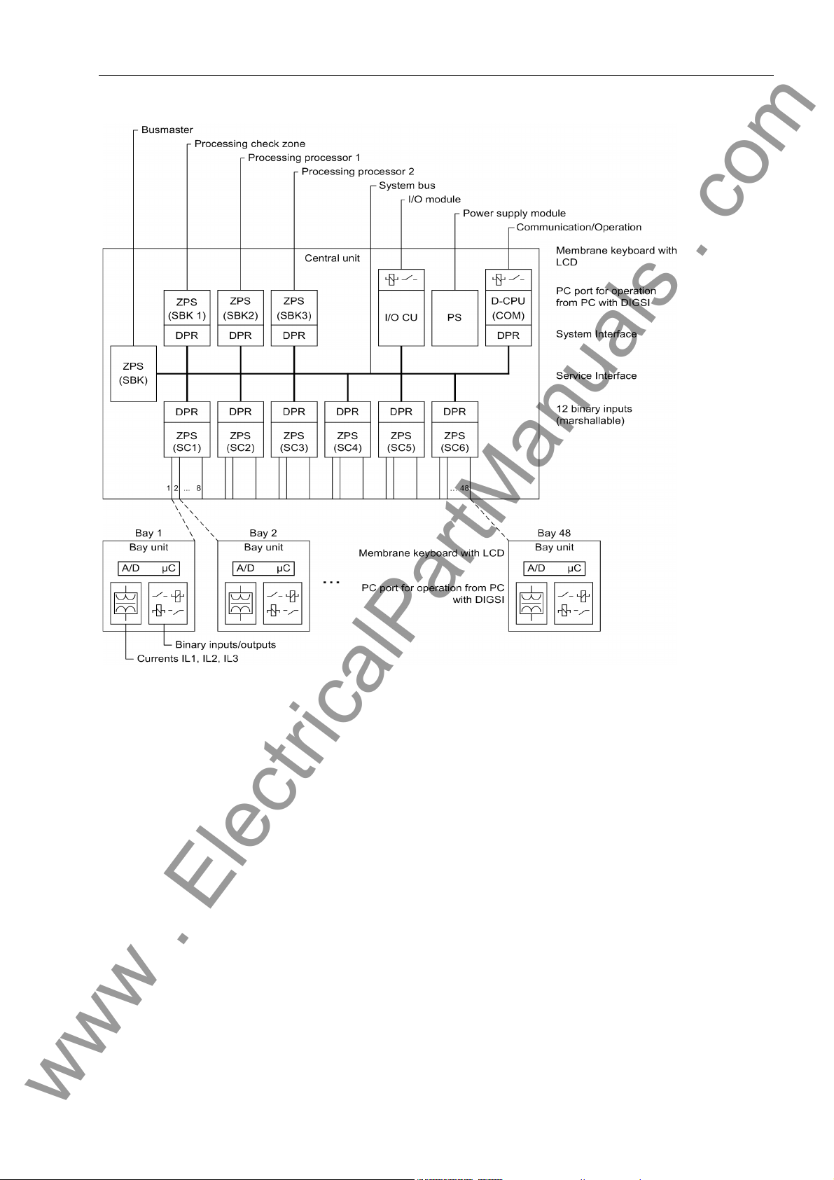
The SIPROTEC 7SS52 V4 distributed busbar and breaker failure protection consists
of compact bay units which are connected to the central unit by fiber-optic cables. Figure 1-1, page 3 shows the basic structure of the protection system.
All tasks from acquisition of the measured values up to the commands to the circuit
breakers are exclusively processed in a digital manner.
In the bay units the feeder or coupler currents are measured time-synchronized, digitalized, preprocessed and transmitted to the central unit via the fast serial port. The
input nominal current can be 1 or 5 A depending on the main current transformer design. A full galvanic and low-capacitive isolation of the measuring inputs is provided
by transducers. Suppression of disturbances is achieved by filters which are optimized
for the measured value processing with regard to bandwidth and processing speed.
Bay units The bay units can be parameterized and operated either directly or from the central
unit. Chapter 6.1, page 210 summarizes the operator options during operation.
The bay units capture the isolator positions and bay-related binary signals, process
functions of the breaker failure protection and fulfil auto diagnosis tasks.
Heavy-duty command relays take the protec ti on system's trip commands directly to
the circuit breakers. Marshallable alarm relays and indicators (LEDs, LC display,
DIGSI communication software) allow event indication. In addition operational measured values are displayed.
For the marshalling of isolator positions, command relays, alarm relays and allocatable binary inputs the DIGSI communication software is used.
Optionally, the bay units can be equipped with a backup protection function (definitetime, inverse-time) including breaker failure protection.
Central unit The central unit reads in time-synchronized measured currents from the connected
bay units and processes them together with binary information from the protection
functions (differential protection, breaker failure protection). The central unit transmits
the results of the calculations cyclically to the bay units, which perform logical combinations of the results.
Freely marshallable alarm relays and LED displays are provided for signalling. They
are marshalled with the DIGSI communication software.
The central unit manages all configuration and setting data for the bu sbar and breaker
failure protection functions. Communication is possible via the serial port by mean s of
a PC utilizing a current version of the DIGSI communication software. With DIGSI V4.6
the central unit - but not the bay unit - can also be operated via IEC 61850 with the
optional EN100 module. Indications, parameters and measured values are visualized
in the display or in DIGSI. In addition the pro gram can read ou t fault data from the protection device and analyze it.
The central unit and bay units contain power supply modules for a reliable powe r supply on different voltage ranges.
2
7SS52 V4 Manual
C53000-G1176-C182-3
Page 19
Overall Operation
www . ElectricalPartManuals . com
SBK: Protection processing SC: Serial coupling
DPR: Dual port RAM PS: Power supply
I/O CU: Input/output central unit ZPS: Central processor protection
SBK: Bus master
Figure 1-1 General view of the configuratio n of the protection system
7SS52 V4 Manual
C53000-G1176-C182-3
3
Page 20

Introduction
www . ElectricalPartManuals . com
1.2 Applications
Application The SIPROTEC 7SS52 V4 distributed busbar and breaker failure protection is a se-
lective, reliable and fast protection for busbar short-circuits and circuit-b reaker failures
in medium-voltage, high-voltage and extra high-voltage switching stations. It is suitable for almost all busbar configurations.
The busbar protection uses a phase-selective measuring principle.
The protection system consists of a central unit (CU) and up to 48 bay units (BU) con-
nected by fiber-optic (FO) cables. The latter can be located in the vicinity of the bays
(distributed) but also together with the CU in cubicles (centralized).
Use and scope of
functions
The protection can be used with all types of switchgear with either conventional or linearized CTs.
The modular design facilitates extensions or modifications of the protection system in
conformity with the switchgear design.
The 7SS52 V4 is designed for 12 selective bus zones and 12 bus coupler (auxiliary
bus) sections. These are sections which serve exclusively for coupling of the bus
zones. They do not have any feeders. The busbar co nfigura tion can includ e up to 24
sectionalizing isolators and 16 bus couplers with one bay unit or 8 bus couplers with
two bay units.
By virtue of the universal isolator replica, the SIPROTEC 7SS52 V4 distributed busbar
and breaker failure protection can be matched with differ ent b usbar configu ra tions in
the design phase.
Compensation of different current transformer ratios is achieved by parameter setting.
Interposing current transformers are thus no more required.
A busbar short-circuit is detected by evaluating the differential current and the stabilizing current. Appropriate measures ensure corr ect performance even for extreme CT
saturation (requested current transmission time ≥ 2 ms for stability in the case of external faults and ≥ 3 ms for tripping).
The integrated circuit breaker failure protec tion (CBF) can be operated in five modes,
selectable per bay (see Chapter 5.3.5.2, page 119):
• I> query (1-stage CBF)
• TRIP repetition with overcurrent detection I> (2-stage CBF)
• Unbalancing (1-stage CBF)
• TRIP repetition with following unbalancing (2-stage CBF)
• Single-pole or three-pole start by external CBF and tripping via the isolator replica
In addition, the integrated circuit breaker failure protection provides two operating
modes that can be set in parallel to the other five modes (see Chapter 5.3.5.2, page
119):
• Low-current operating mode without/with TRIP repetition
• Pulse mode
4
7SS52 V4 Manual
C53000-G1176-C182-3
Page 21

1.3 Features
www . ElectricalPartManuals . com
Features
The overcurrent-time protection is a back-up protection function of the bay unit an d includes the following functions (see Chapter 5.16, page 188):
• Phase-selective high-set stage (I>>)
• High-set stage for the earth current (IE>>)
• Phase-selective overcurrent stage with definite time or inverse time characteristic
(I> / Ip)
• Overcurrent stage for the earth curren t with definite time or inverse time character-
istic (IE> / IEp)
Back-up protection function, can work without the central unit
Separate circuit breaker failure protectio n
• Powerful multiprocessor system
• Completely digital measured value processing and co ntrol, from the acquisition and
digitizing of measured values, recognition of the isolator status and processing of
the CB failure protection signals up to the trip decisions for the circuit-breaker
• Graphical station planning with the DIGSI communication software
• Easy station configuration with the DIGSI communication software
• Easy centralized operation of bay units from the central unit using DIGSI, or local
menu-guided operation via integrated keypad and display panel
• Battery-buffered storage of fault events as well as instantaneous values for fault recording
• Complete galvanic and disturbance-free isolation betwe en the internal processing
circuits of central unit and bay units and the measuring and auxiliary supply circuits
of the station by virtue of screened measuring transducers, binary input and output
modules and DC converters
• Disturbance-free and fast data transmission from and to the bay units by fiber-optic
links
• Complete scope of functions for the selective protection of multiple busbar systems
• Central administration of the isolator states
• Continuous monitoring of measured values as well as of hardware an d software of
the unit
• Comprehensive self-monitoring provides for fast signaling of unit failures
• Communication via electrical or optical interfaces and use of the DIGSI communi-
cation software for planning, parameterization and for indication and fault record
analysis
• Communication check via Web browser
• IEC 61850
• Control center link of the central unit as per IEC 60870-5-103 and IEC 61850
7SS52 V4 Manual
C53000-G1176-C182-3
5
Page 22

Introduction
www . ElectricalPartManuals . com
• Output of indications to
− Control center
− LEDs
− Binary outputs of the central unit
• Commissioning support by measuring and display functions, and output of indica-
tions to a control center as well as to LEDs and outputs of the central unit.
Busbar
protection
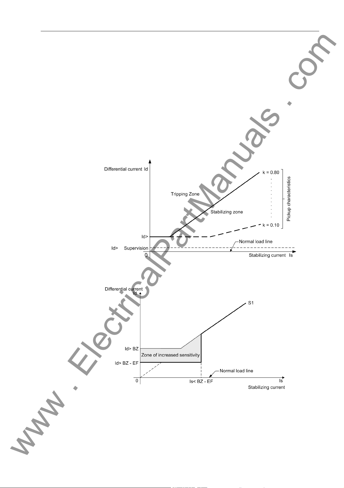
The digital busbar protection contains the following functions:
• Evaluation of the differential current in conjunction with through-current stabilization
(Figure 1-2, page 7)
• Trip decision based on 3 independent measurements. 2 mea surements are based
on busbar configuration, and the third measurement considers all busbar sections
independent of the isolator replica (check zone).
• Fast tripping (typical trip time 15 ms)
• Busbar protection with up to 12 bus zones (BZ), 12 bus coupler (auxiliary bus) sec-
tions (AB) and up to 48 bay units
• Protection of systems with up to quintuple busbars (including transfe r busbars)
• Stabilization against spurious tripping in case of external faults and CT saturation
• Zone-selective and phase-selective blocking of the busbar protection by the differ-
ential current monitor
• Selective blocking of the bus section in case of
− Isolator faults
− Bay faults (bay unit, FO cable)
− Measured value error
− Response of the zero crossing supervision
• Characteristics for check zone and bus-selective zones can be set independently
from each other
− Normal pick-up characteristic (Figure 1-2, page 7)
− Earth fault characteristic (Figure 1-3, page 7)
• Matching to different CT ratios without interposing matching transformers
• Selective clearance of short-circuits even on the bypass bus with signal transmis-
sion to the remote end
• Detection and disconnection of short-circuits in the coupler bay betwee n current
transformers and circuit-breaker based on current measurement and selective unbalance
• Detection and disconnection of short-circuits between current transformers and circuit-breaker of a line by end fault protection
6
7SS52 V4 Manual
C53000-G1176-C182-3
Page 23
Features
www . ElectricalPartManuals . com
• Circuit breaker failure protection (CBF), selectable per bay, for low-current faults in
the variants
− I> query (1-stage CBF)
− TRIP repetition with overcurrent detection I> (2-stage CBF)
− Unbalancing (1-stage CBF)
− TRIP repetition with following unbalancing (2-stage CBF)
− Single-pole or three-pole start by external breaker failure pro tection and tripping
via the isolator replica
• Direct operation of the circuit breaker by the ba y un it
• Direct tripping of busbar sections via binary inputs of the central unit
Figure 1-2 Pick-up characteristics of the busbar and breaker failure protection (unbalancing)
Figure 1-3 Earth fault characteristic
7SS52 V4 Manual
C53000-G1176-C182-3
7
Page 24

Introduction
www . ElectricalPartManuals . com
Breaker failure
protection
The integrated circuit breaker failure protection (CBF) contains th e following functions:
• In case of a busbar short-circuit, a breaker failure is detected by co mparison of current thresholds.
• In all operating modes of the circuit breaker failure protection, a bay-selective command is output by the bay units to trip the circuit breaker at the remote end (transfer
trip command).
• The external breaker failure protection can be started for one phase or for three
phases.
• The breaker failure protection can be started on 1 channel or, for extra reliability, on
2 channels. Both settings can be combined with a monitoring feature.
• Reduced response times in case of a circuit breaker malfunction
• Query of the circuit breaker position in case of low-current faults
• The circuit breaker failure protection function can be deactivated fo r te st purp oses.
The following modes are available for the circuit breaker failure protection:
• I> query:
After initiation by a TRIP command from the feeder protection, the 7SS52 V4
checks the feeder current. If the measured current stays above the set threshold after a set time has elapsed, the 7SS52 V4 issues zone- selective TRIP commands in
the bays considering the isolator replica.
• TRIP repetition with subsequent I> query:
When initiated by a TRIP command from the feeder protection, the 7SS52 V4 issues a second TRIP command to the circuit breaker of the initiating feeder after a
set time delay. In case this second TRIP command is also unsuccessful, tripping as
per mode I>query is effected.
• Unbalancing:
After initiation by a TRIP command from the feeder protection, the
7SS52 V4 system checks the feeder current. If the measured current stays above
the set threshold after a set time has elapsed, the polarity of the current in this feeder is inverted by the 7SS52 V4 (unbalancing).
• TRIP repetition with subsequent unbalancing:
When initiated by a TRIP command from the feeder protection, the 7SS52 V4 issues a second TRIP command to the circuit breaker of the initiating feeder after a
set time delay. In case this second TRIP command is also unsuccessful, tripping as
per mode Unbalancing is effected.
• TRIP by external CBF:
Where a separate circuit breaker failure protection is provided, the 7SS52 V4 can
generate zone-selective feeder trip commands utilizing the integrated isolator replica.
• TRIP repetition with subsequent unbalancing with pulse trigger or I>query:
This mode should be used when the CBF is triggered by the remote station. The
function is triggered by a trip command from the feeder protection at the remote
feeder terminal. The further proceeding is described in the modes TRIP repetition
with subsequent unbalancing and I>query.
• Low-current CBF:
This mode outputs a TRIP command even in the case of low-cur rent faults (e.g. tripping by Buchholz protection). After a settable time the circuit breaker position is
queried. A TRIP repetition also takes place with a low-current oper ating mode.
8
7SS52 V4 Manual
C53000-G1176-C182-3
Page 25

Features
www . ElectricalPartManuals . com
End fault protection This mode detects short-circuits between the current transformers and the circuit
breaker and generates the necessary commands to disconnect the faulted line.
Overcurrent
protection
Isolator
replica
The overcurrent protection of the bay unit is independent of the busbar protection
function and of the central unit. The overcurrent protection comprises the following
functions (Chapter 5.16, page 188):
• High-set stage I>> with separate fault detection in each phase
• High-set stage IE>>
• Definite time overcurrent stage I> with separate fault detection in each phase OR
• Inverse time overcurrent stage Ip with separate fault detection in each phase
• Definite time earth current stage IE> OR
• Inverse time earth current stage IEP
• Setting of different current/time characteristics for phase and earth currents is pos-
sible.
• With inverse time O/C protection: three standardized characteristics are selecta ble
for phase currents and earth currents.
• The CBF function remains active even in case of central unit failure or with the bay
unit out of service.
The isolator replica is common for the busbar protection and the circuit-brea ker failure
protection function. The isolator replica comprises the following functions:
• Management of up to 48 bay units, 12 bus zones and 12 bus coupler sections:
The protection system is suitable for configurations up to quintuple busbars. Combibus operation is possible. Up to 16 couplers can be configured with one bay unit,
and up to 8 couplers with 2 bay units. These can be bus couplers or/and sectionalizing isolators.
Trip output / Trip reset
• Isolator running time supervision
• Integrated storage of isolator status on loss of DC supply:
The isolator replica allows to allocate to the isolators their positions prior to the DC
supply failure. It is also possible to allocate to all isolators of this feeder the position
CLOSED. The allocation of NOT OPEN = CLOSED eliminates the necessity of calibrated isolator auxiliary contacts. Also, it ensures stable functioning of the protection even in case of a wire break.
• Graphical planning of the station configuration with the DIGSI communication software
• Visualization of isolator positions by LEDs on the bay units
The signal processing is distinguished by the following characteristics:
• Feeder-selective TRIP command by the bay units
• Feeder-selective selectable overcurrent release of the TRIP command
• Extension of busbar TRIP signal for set time
• Current-controlled reset of TRIP signal
7SS52 V4 Manual
C53000-G1176-C182-3
9
Page 26

Introduction
www . ElectricalPartManuals . com
Fault recording During a fault event, the instantaneous values of the measured values are stored at
intervals of 1 ms at 50 Hz and 0.83 ms at 60 Hz respectively in a buffer of the central
unit or of the bay units. The central unit calculates from the instantaneous valu es the
differential and restraint currents of each phase for all busbar sections and the check
zone. The bay units calculate from the instantaneous values the currents and the binary tracks.
After starting the fault recording, the fault data are stored in a range from max. 500 ms
before the TRIP command to max. 500 ms after it. Th e central un its can sto re up to 8
faults with a maximum of 80 fault events each, an d ea ch bay unit can sto re 8 faults
with a maximum of 100 fault events each. Where more events are gener ated, the oldest are overwritten in the order of their generation. Fault recording is started, for instance, by a busbar short circuit, by a binary input or through DIGSI.
The fault data can be read out to a PC and evaluated by the DIGSI communication
software. The fault record data buffer SIPROTEC 7SS52 V4 is protected aga inst data
loss in case of power failures.
Relays,
LEds and
binary inputs
of the central unit 12 binary inputs are available to control the functions of the central unit (e .g. clock syn-
of the bay unit The bay units are the interface link to the station.
All inputs and outputs are freely marshallable.
Each LED or relay can be allocated to more than one event; likewise, events can be
marshalled more than one LED or relay.
chronization, LED reset).
16 alarm relays and 32 LED in the central unit can be allocated to various functions
for user-specific output and indication.
Each bay unit 7SS523 has
• 4 command relays with each 2 NO contacts
• 1 command relay with 1 NO contact
• 1 command relay with 1 NO contact
• 1alarm relay with 2 NC contacts (device failure, not marshallable)
The functional allocation of the outputs can be marshalled with the DIGSI communication software.
20 freely marshallable binary inputs are available for control functions or state recognition.
16 binary inputs can be marshalled to various functions, such as recognition of the isolator states.
10
7SS52 V4 Manual
C53000-G1176-C182-3
Page 27

Features
www . ElectricalPartManuals . com
Each bay unit 7SS525 has
• 3 command relays with each 2 NO contacts
• 2 command relay with 1 NO contact
• 1 command relay with 1 NO contact
• 1 alarm relay with 1 NC contact (device failure, not marshallable)
The functional allocation of the outputs can be marshalled with the DIGSI communication software.
10 freely marshallable binary inputs are available for control functions or state recognition.
1 LED is freely allocable.
Measuring and
testing functions
The SIPROTEC 7SS52 V4 distributed busbar and circuit br eaker failure provides a variety of measuring and testing functions to assist during commissioning and maintenance. These functions are:
• Display of the feeder currents per phase in each bay unit and in the central unit. In
addition the data are available at the serial port for visualization in the DIGSI software.
• Phase-selective and zone-selective calculation of differential and stabilizing currents. Display in the DIGSI software through the serial PC port. In addition, the data
are visualized per phase, per bus zone, a nd for the checkzone, in the display of the
central unit. The display of the bay unit shows only the data for the check zone.
• Monitoring of the zone-selective and phase-selective differential currents with zoneselective blocking or alarm output
• Monitoring of the zone-selective and phase-selective differential currents with zoneselective blocking or alarm output
• Phase-selective trip test including control of the feeder circuit breaker (through
DIGSI, bay unit display or binary input)
• Bay out of service
Removal of one bay from the busbar protection processing via central unit or bay
unit, e.g during maintenance works.
• Revision mode
The isolator replica of one bay is retained by the central and the bay unit with the
protection function remaining active.
• Cyclic test of measured value acquisition, measured value processing and trip circuit test including the coils of the command relays
• Manual blocking
Blocking of the circuit breaker failure protection, the XMZ and the backup breaker
failure protection and of the TRIP commands.
7SS52 V4 Manual
C53000-G1176-C182-3
11
Page 28

Introduction
www . ElectricalPartManuals . com
Event buffer in central unit
Event buffer in
bay unit
Self
monitoring
The SIPROTEC 7SS52 V4 distributed busbar and circuit breaker failure protection
supplies battery-buffered data for the analysis of faults as well as for operational
events.
Up to 200 operational events and 80 fault events with real-time information are stored
in a circulating buffer in the central unit.
Operational events include switching operations, protection status indications, isolator
status irregularities and monitoring functions.
Fault events include trip signals in the event of busbar short-circuits, circuit-breaker
failure and transfer trip.
Up to 50 operational events and 100 fault events per fault.
Hardware and software are continuously monitored; irregulari ties are recognized instantly and annunciated.
A high degree of security and availability is achieved by the continuous monitoring of:
• Isolator statuses
• Trip circuits
• Measured current circuits
• Measured value transformations
• Supply voltages
• Program memories
• Program processing
• Discharge degree of battery (central unit and bay unit)
For diagnosis purposes in the event of device failures, a battery-buffered dedicated
data memory is available in the central unit.
Clock control • Central unit
− Battery-buffered time with 1 ms resolution
− Time set by entry of current data
− Synchronization of the central unit via binary input or system port (synchroniza-
tion signal DCF77, IRIG B by satellite receiver)
− IEC 60870-5-103 and IEC 61850
• Bay unit
− Battery-buffered time with 1 ms resolution
− Clock synchronization by central unit in intervals of 1 minute
− Local clock setting possible as well
Battery-buffered
functions
12
The central unit and the bay units are equipped with buffer batteries to ensure that
LED states, date and time, operational and fault events as well as fault records are
maintained in case of an auxiliary power failure.
7SS52 V4 Manual
C53000-G1176-C182-3
Page 29

Design and Connection System 2
www . ElectricalPartManuals . com
This chapter describes the design of the central un it and the bay u nits that con stitute
the SIPROTEC 7SS52 V4 distributed busbar and breaker failure protection. It explains
what housing versions are possible and what connection methods are used.
2.0 General 14
2.1 Central Unit 15
2.2 Bay Unit 18
2.3 Connection Method 22
137SS52 V4 Manual
C53000-G1176-C182-3
Page 30

Design and Connection System
www . ElectricalPartManuals . com
2.0 General
The SIPROTEC 7SS52 V4 distributed busbar and breaker failure protection is comprised of:
• Central unit
• Bay units
• Data links (fiber-optic cables)
Prefabricated fiber optic cables with double-end ST plug connectors are used for th e
data exchange.
They can be delivered with specific anti-rodent protection for outdoor installation. Indoor cables may be used for centralized configuration of the bay units.
Power supply The modules in the bay unit and central unit are powere d by powerful power supply
units. For the range required for your specific input voltage, please refer to the selection and ordering data in the Table A-1, page 336.
Bonding power failure
Short dips or failures of the supply voltage up to 50 ms, which may occur due to shortcircuits in the DC supply system of the station, are compensated by a DC storage capacitor (for nominal voltages ≥ 60 V).
14
7SS52 V4 Manual
C53000-G1176-C182-3
Page 31
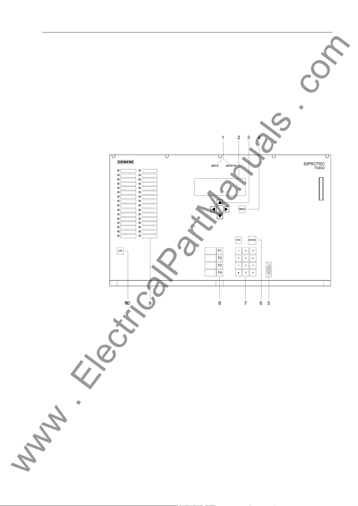
2.1 Central Unit
www . ElectricalPartManuals . com
The central unit is installed in an ES902 C (SIPAC) subrack.
On account of the modular design, different variants and degrees of expansion can be
coordinated with the station configuration.
2.1.1 Front View
Central Unit
7SS52 V4 Manual
C53000-G1176-C182-3
Figure 2-1 Front view of the central unit
1 LEDs for the indication of operating states
2 LCD for textual display of process and device information
3 Navigation keys for moving through the operating tree
4 MENU key for calling up the main menu
5 9-pole female sub D connector for connecting a PC running DIGSI
6 ENTER for confirmation of changes or for acknowledging information displayed
in the LCD
ESC key to move up one level
7 Numeric keypad for entering numeric values
15
Page 32

Design and Connection System
www . ElectricalPartManuals . com
8 Function keys:
Alarm list
F1
F2 Operational events
F3 Measured values
F4 Last fault
9 freely parameterizable LEDs for display of process or device information. Next
to the LEDs, there is a labeling strip for labeling of the function of each LED.
10 LED key for testing and resetting the LEDs
2.1.2 Modules and Submodules
Power supply module (SV)
Communication
module (D-CPU)
Input/output
module (EAZ)
Figure 2-2 Module arrangement in the central unit
The power supply (SV) has a width of 4 standard mounting spaces.
Each of the other units has a width of 2 standard mounting spaces.
The communication module (D-CPU) is used for communication between the central
unit and the DIGSI software. It also offers a control center interface, a service port and
5 binary inputs. An integrated electrical EN100 module for the communication via
IEC 61850 is optionally available.
The I/O module (EAZ) comprises 16 alarm relays.
16
7SS52 V4 Manual
C53000-G1176-C182-3
Page 33

Central Unit
www . ElectricalPartManuals . com
Processor
modules (ZPS)
Fiber-optic
module (LMZ)
Terminal blocks On the rear side of the central unit, terminal blocks are provided for the extern al e lec-
The 4 processor modules (ZPS-SBK; ZPS-BSZ1 to ZPS-BSZ3) provide the protection
functions.
Another 1 to 6 modules (depending on the system configuration) are used for communication with the interfaces (ZPS-SK1 to ZPS-SK6) to ensure the data exchange with
the bay units. Each module can exchange data with up to 8 bay units.
There are different ZPS-modules (ZPS and ZPS2). The ZPS2-module may only be
used with a firmware V4.61 or higher. The mixed use (ZPS/ZPS2-modu les) is allowed.
From release 7SS522... /HH and higher the ZPS2-module is supplied generally.
For each ZPS-SK-module there is an electrical/optical signal converter module (LMZ,
with 8 optical interfaces each), fitted on the device's rear side. The receiver and transmitter connection points per bay unit are consecutively numbered on the central unit's
rear plate.
trical connection of the power supply module (SV), the I/O module (EAZ) and the communication module (D-CPU). For each electrical connection point, there is one screwtype and one snap-in connector for the statio n wirin g . Th e term i na l bloc ks ar e ide nt ified according to their position in a coor dinate system. The conn ections inside a block
are numbered from left to right, see the example in Figure 2-6, page 22.
2.1.3 Design
Subrack ES902 C
(SIPAC)
The subrack ES902 C (SIPAC) consists of an aluminium frame covered from all sides
by metal plates. The front and the rear plate are hinged and can be opened downwards for easy servicing.
The dimensions of the housing can be in Figure 9-2, page 329.
7SS52 V4 Manual
C53000-G1176-C182-3
17
Page 34

Design and Connection System
www . ElectricalPartManuals . com
2.2 Bay Unit
The bay units are available in a 7XP20 housing for panel flush mounting and cubicle
mounting, or in a housing for panel surface mounting for bay unit 7SS523.
2.2.1 Front View
Figure 2-3 Front view of the bay unit 7SS523 and 7SS525
1 LEDs for the indication of operating states
2 LCD for textual display of process and device information
3 Navigation keys for mo vin g thr oug h th e op er at ing tre e
4 MENU key: no function
5 ENTER key:
for confirmation of inputs,
for entering the next level, or
for switching between ordering code (MLFB) and operational measured va lues
ESC key to move up one level
6 Function keys:
F1 Direct access to the operating tree for changing the mode
F2 Starts the circuit breaker test
F3: Direct access to the operating tree for switchin g the re visio n fu nc tio n
F4: Transformer polarity reversal
7 9-pole female sub D connector for connecting a PC running DIGSI
18
7SS52 V4 Manual
C53000-G1176-C182-3
Page 35

8 LED key for testing and resetting the LEDs and for display of operational
www . ElectricalPartManuals . com
measured values in 4-line mode
9 Freely parameterizable LEDs for display of process or device information. Next
to the LEDs, there is a labeling strip for labeling of the function of each LED.
10 Freely parameterizable LED.
2.2.2 Modules and Submodules
Bay Unit
Figure 2-4 Module arrangement in the bay unit 7SS523
PFE module In the PFE module the firmware is located and processed; it also contains the current
transformers and the measured value acquisition function.
SAF module The SAF modul e contains the power supply and the alarm and trip relays.
EFE module The EFE contains the binary inputs and receives indications (e.g. from isolators and
circuit breakers).
Heavy-duty
current terminals
Plug-in modules The plug-in modules are identified according to their position in a coordinate system.
The heavy-duty current terminals automatically short-circuit the current transformer
when the module is withdrawn.
The connections inside a module are numbered consecutively from left to right
(viewed from the rear), see example in Figure 2-8, page 24.
7SS52 V4 Manual
C53000-G1176-C182-3
19
Page 36

Design and Connection System
www . ElectricalPartManuals . com
Figure 2-5 Module arrangement in the bay unit 7SS525
PFE/SVW module In the PFE/SVW module the firmware is located and processed; it also contains the
power supply, the current transformers and the measured value acquisition function.
AFE module The AFE module contains the alarm and trip relays.
EFE_10 module The EFE_10 contains the binary inputs and receives indications (e.g. from isolators
and circuit breakers).
Heavy-duty
current terminals
Plug-in modules The plug-in modules are identified according to their position in a coordina te system.
The heavy-duty current terminals automatically short-circuit the current transformer
when the module is withdrawn.
The connections inside a module are numbered consecutively from left to right
(viewed from the rear), see example in Figure 2-8, page 24.
20
7SS52 V4 Manual
C53000-G1176-C182-3
Page 37

2.2.3 Design
www . ElectricalPartManuals . com
2.2.3.1 Panel Surface Mounting
For panel surface mounting, only possible for device 7SS523, the ba y units are delivered in casings type 7XP20. The front plate is hinged and can be pulled out with a
plastic tab and swung to the left for easy servicing .
All signals including the auxiliary voltage are connected to two-tier terminals. In each
tier the terminals are numbered from left to righ t (F igu r e 2- 7, pa g e 23).
For the fiber-optic interface, 2 ST connectors are provided at the bottom of the device
next to the terminal strip.
Earthing screws are provided at the left side of the housing.
The dimensions of the housing can be in Figure 9-4, page 331.
2.2.3.2 Panel Flush Mounting or Cubicle Mounting
For panel flush mounting or cubicle mounting the bay units are delivered in casings
type 7XP20. With the bay unit 7SS523 the fr ont plate is h inged and can be pulled out
with a plastic tab and swung to the left for easy servicing. With the bay unit 7SS525
the front plate can be removed.
Bay Unit
All signals including the auxiliary voltage are connected to terminal blocks on the rear
plate. For each electrical connection point, there is one screw-type and one snap-in
connector for the station wiring.
For the fiber-optic interface, 2 ST connectors are provided at the rear of the device
next to the terminal strip.
An earthing screw is provided at the back of the housing.
The dimensions of the housing can be in Figure 9-5, page 332.
7SS52 V4 Manual
C53000-G1176-C182-3
21
Page 38

Design and Connection System
www . ElectricalPartManuals . com
2.3 Connection Method
2.3.1 Location of Device Connections
Central unit
Figure 2-6 Device connections on central unit
22
7SS52 V4 Manual
C53000-G1176-C182-3
Page 39

Bay unit
www . ElectricalPartManuals . com
Panel surface
mounting
Connection Method
Figure 2-7 Device connections on bay unit 7SS523 for panel surface mounting
7SS52 V4 Manual
C53000-G1176-C182-3
23
Page 40

Design and Connection System
www . ElectricalPartManuals . com
7SS523 bay unit
Panel flush mounting or
cubicle mounting
24
Figure 2-8 Device connections on bay uni t for panel flush mounting or cubicle mounting
7SS52 V4 Manual
C53000-G1176-C182-3
Page 41

7SS525 bay unit
www . ElectricalPartManuals . com
Panel flush
mounting or
cubicle mounting
Connection Method
Figure 2-9 Device connections on bay unit 7SS525
2.3.2 Device Connections
Table 2-1 Overview of device connections
Variant Current connections Voltage connections FO connections
Central unit Screw connection
for max. 1.5 mm²
and
Double leaf-spring-crimp contact for max. 1.5 mm²
Bay unit
Panel surface
mounting
Bay unit
Panel flush mounting or
cubicle mounting
Screw connection
for max. 4 mm²
and
Double leaf-spring-crimp
contact for max. 2.5 mm²
Screw-type terminals
for stranded wires with max. 4 mm²
or
for solid wires with max. 7 mm²
Screw connection
for max. 1.5 mm²
and
Double leaf-spring-crimp contact for max. 1.5 mm²
Integrated
ST connector for
FO connection,
glass fiber 62.5/125 µm
FO duplex outdoor cable or
FO duplex indoor cable
Integrated
ST connector for
FO connection,
glass fiber 62.5/125 µm
Integrated
ST connector for
FO connection,
glass fiber 62.5/125 µm
7SS52 V4 Manual
C53000-G1176-C182-3
25
Page 42

Design and Connection System
www . ElectricalPartManuals . com
2.3.2.1 Screw-Type Terminals
Connection The voltage connections of the central unit and the voltage and current conn ections of
the bay units have screw terminals. For assignment of the terminals, please refer to
the Figures A-3, page 342 and A-5, page 345 in the Appendix.
Connection method Use copper conductors only!
You can use solid conductors or stranded conductors with end sleeves.
You can use end sleeves with plastic collar (acc. to DIN 46228 P. 1) that have a cross-
section between 0.5 mm
Conductor
cross-section
0.5 mm
0.75 and 1 mm
1.5; 2.5 and 4 mm
Tools Use a screwdriver for slot-head screws size 6 × 1.
Use a crimping tool for end sleeves between 0.5 mm
AWG 20 to 10) with or without plastic collar.
2.3.2.2 Double Leaf-Spring-Crimp Contacts
Connection The voltage connections of the central unit and the voltage and current conn ections of
the bay units have double leaf-spring-crimp contacts. For assignment of the ter minals,
please refer to the Figures A-3, page 342 and A-5, page 345 in the Appendix.
Connection method
(current terminals)
Use copper conductors only!
Use stranded conductors with a cross-section between 1.5 mm
2
and 4 mm2 (equivalent to AWG 20 to 12) and a length up to:
Length (without collar)
2
10 mm
2
12 mm
2
18 mm
2
and 6 mm2 (equivalent to
2
and 2.5 mm2.
Use double leaf-spring-crimp contacts type L with 2 snap lugs that match the selected
conductor cross-sections.
Connection method
(voltage
terminals)
Tools Use a crimping tool for the double leaf-spring-crimp contacts.
26
Use copper conductors only!
Use stranded conductors with a cross-section between 0.5 mm
Use double leaf-spring-crimp contacts that match the selected conductor cross-sec-
tions.
2
and 1 mm2.
7SS52 V4 Manual
C53000-G1176-C182-3
Page 43

Connection Method
www . ElectricalPartManuals . com
2.3.2.3 D-SUB Female Connectors
Connectors The serial ports of the central unit and of the bay units have 9-pole D-SUB female con-
nectors. The serial ports include:
• the PC port at the front of the central unit and the bay unit
• the service port at the back of the central unit
• the system port at the back of the central unit
• the clock synchronization interface at the back of the central unit
For assignment of the connectors, please refer to the Figu res A-3, page 342 and A-5,
page 345 in the Appendix.
Connection method You can use any standard 9-pole D-SUB plug connectors per MIL-C-24308 and
DIN 41652.
Depending on the device version, the pin assignment is the same as for an RS232 or
RS485 port.
You can use for connection e.g. a 5-strand, shielded interface cable.
Tools No tools are required for connection the interface cab l e s.
2.3.2.4 Fiber-Optic Cable Connections
Central unit Depending on the variant ordered, the service and the system port on the rear of the
central unit may have additional fiber-optic connections (Figure 2-6, page 22).
Moreover, the central unit is connected with the bay units by fiber-optic cables. The
bay unit connectors are located on the back of the central unit (Figure 2-6, page 22).
Bay units Depending on the mounting variant, the fiber-optic interface to the central unit is locat-
ed on the bottom (Figure 2-7, page 23) or the rear (Figure 2-8, page 24) of the bay
unit. For assignment of the connectors, please refer to Figure A-4, page 343 in the Ap pendix.
Connection method FO connector type: ST connector
Use fiber type: Multimode FO,
G50/125 µm,
G62.5/125 µm,
G100/140 µm
for wave length: λ approx. 820 nm
7SS52 V4 Manual
C53000-G1176-C182-3
27
Page 44

Design and Connection System
www . ElectricalPartManuals . com
Note
The bending radius of the available FO cables may not be smaller than 200 mm for
outdoor cables and 80 mm for indoor cables.
If you use other fiber types than those recommended above, please make sure to observe the manufacturer’s specifications.
By using the fiber types G50/125 µm and G62,5/125 µm, compliance with class 1 acc.
to EN 60825-1 is ensured.
2.3.2.5 EN100 module Ethernet (IEC 61850)
The IEC 61850 is a manufacturer- and device-independent communication protocol.
The data transmission between PC and SIPROTEC 4 device thus becomes much
faster than via the system inferface. This protocol is available for most of the SIPROTEC 4 devices such as e.g. 7SS522 as of version V4.6.
For a detailed description, please refer to th e manua l Eth ernet & IEC 6 185 0 Start Up
/6/.
Ethernet
connection
8-pin RJ45 connectors (100Base-T in acc. with IEEE 802.3) serve as connections for
the wired Ethernet100 interfaces.
ETHERNET - EN100-E
Ch2Ch1
123
Figure 2-10 Ethernet connection
Connector type:RJ45 connector in acc. with IEEE 802
Lines: 150 W STP (shielded twisted-pair)
Note
For the implementation of an optical IEC 61850 interface, an external converter is
additionally required.
6
123
6
28
7SS52 V4 Manual
C53000-G1176-C182-3
Page 45

Getting Started 3
www . ElectricalPartManuals . com
This chapter describes the first steps that you should take after receiving your
SIPROTEC 7SS52 V4 system.
After unpacking, please check whether the version and rated data match your requirements. Match the rated control voltages of the system components to your station conditions and insert the buffer batteries.
Next, set up the communication between th e cen tr al un it and th e ba y un its. For an
electrical check, you can now navigate in the user interface without any measured values. You can also connect the system to a PC and operate it from the computer using
the DIGSI software. In the last section you will find hints on what to observe for a longterm storage of the system.
3.1 Unpacking and Repacking 30
3.2 Checking the Rated Data 30
3.3 Matching the Control Voltage for the Binary Inputs and Inserting the
Buffer Battery 31
3.4 Electrical Checks 38
3.5 Setting up the Communication between the Central Unit and the Bay Unit 39
3.6 Operation of SIPROTEC Devices from the Operator Panel 40
3.7 Storage 44
297SS52 V4 Manual
C53000-G1176-C182-3
Page 46

Getting Started
www . ElectricalPartManuals . com
3.1 Unpacking and Repacking
The protection system is packaged at the factory to meet the requirements of IEC
60255-21.
Unpack and pack the devices with normal care, without using force, and with appro-
priate tools.
Visually check the device immediately upon arrival for correct mechanical condition.
Please observe the instruction leaflet and any other documentation that may be part
of the delivery.
Check also that the accessories included in the delivery are complete.
(Table A-4, page 338).
You can use the transport packing in the same manner for fu rther sh ipme nt. Sto rage
packaging alone, for individual devices, is not sufficient for shipping. If you use other
packaging, make sure that the shock requirements under IEC 60255-21-1 Class 2
and IEC 60255-21-2 Class 1 are met.
Note
The device must be in the final operating area for a minimum of two hours before the
power source is first applied. This time allows the device to attain temperature equilibrium, and dampness and condensation to be avoided.
3.2 Checking the Rated Data
First of all, check the complete ordering code (MLFB) of the system to ensure that the
version delivered complies with the required rated data and functions.
The complete ordering code can be found on the rating plates on the back of the housings. The meaning of its digits is shown in Appendix Chapter A.1, p age 336. The most
important point is the matching of the rated device data to the station ratings, such as
rated auxiliary voltage and rated currents of the CTs. This information is also found on
the rating plate.
30
7SS52 V4 Manual
C53000-G1176-C182-3
Page 47

Matching the Control Voltage for the Binary Inputs and Inserting the Buffer Battery
www . ElectricalPartManuals . com
3.3 Matching the Control Voltage for the Binary Inputs and Inserting the Buffer Battery
Control voltage
Warning!
Only one jumper may be fitted per binary input.
When delivered, the binary inputs of the EAZ and D-CPU modules in the central unit,
and the EFE or EFE_10 modules in the bay units, are config ured for 220 V rated control voltage.
For each binary input, different switching thresholds can be selected. This is done on
the central unit by means of 3 jumpers on the EAZ module and 4 jumpers on the DCPU module, and in the bay units by 3 jumpers each on the EFE or EFE_10 modules.
Central unit
Warning!
Dangerous voltages may be present inside the device!
Make sure to switch the auxiliary voltage off before opening the front panel.
To change the rated control voltages of the binary inputs in the central unit:
Open the front panel. The location of the EAZ and D-CPU module is shown in Fig-
ure 2-2, page 16.
Remove the front plug connectors X3, X4, X5 on the D-CPU module
(Figure 3-2, page 33).
Press down the locking bolt of the modules at the bottom guide rail.
Use the extraction handle (included in the delivery) to pull out the module.
Change the rated control voltages for the binary inputs of the EAZ module as de-
sired by relocating the jumpers (shown in Figure 3-1, page 32 and Table 3-1, page
32).
Change the rated control voltages for the binary inputs of the
D-CPU module by relocating the jumpers (shown in Figur e 3-2, page 33 and Ta ble
3-2, page 33).
To insert the buffer battery into the central unit:
Press the battery firmly into its snap-in holder (see Figure 3-2, page 33) on the D-
CPU module. Observe the correct battery polarit y!
7SS52 V4 Manual
C53000-G1176-C182-3
31
Page 48

Getting Started
www . ElectricalPartManuals . com
Figure 3-1 Location of the jumpers on the EAZ module (central unit)
Table 3-1 Control voltage for the binary inputs on the EAZ (central unit) in relation to the fit-
ted jumper
Name 24 V 60 V 110 V 220 V
BI1 to BI5 (on the D-CPU module, Table 3-2, page 33)
BI6 X31 X21 X11 BI7 X32 X22 X12 BI8 X33 X23 X13 BI9 X34 X24 X14 BI10 X35 X25 X15 BI11 X36 X26 X16 BI12 X37 X27 X17 -
Control voltage setting
32
7SS52 V4 Manual
C53000-G1176-C182-3
Page 49

Matching the Control Voltage for the Binary Inputs and Inserting the Buffer Battery
www . ElectricalPartManuals . com
Figure 3-2 Locati on of the jumpers and the buffer battery on the D-CPU module (central unit)
Table 3-2 Control voltage for the binary inputs on the D-CPU module (central unit) in rela-
tion to the fitted jumper
Connector Binary
inputs
X20, X21 BI1 1, 1 2, 2 3, 3 4, 4
X22, X23BI21, 12, 23, 34, 4
X24, X25BI31, 12, 23, 34, 4
X26, X27BI41, 12, 23, 34, 4
X28, X29BI51, 12, 23, 34, 4
BI6 to BI12 (on the EAZ module, Table 3-1, page 32)
24V 60V 110V 220V
Jumper
7SS52 V4 Manual
C53000-G1176-C182-3
33
Page 50

Getting Started
www . ElectricalPartManuals . com
Bay unit 7SS523
Warning!
Dangerous voltages may be present inside the device!
Make sure to switch the auxiliary voltage off before opening the front panel.
To change the rated control voltages of the binary inputs in a bay unit:
Open the front panel. The location of the EFE module is shown in Figure 2-4, page
19.
Remove the plug connector X1 to the front plate on the EFE module (Figure 3-3,
page 34) and pull out the module.
Change the rated control voltages of the binary inputs to the desired settings, see
Figure 3-3, page 34 and Table 3-3, page 35.
To insert the buffer battery into the bay unit:
Press the battery firmly into its snap-in holder (see Figur e 2-4, page 19) on the PFE
module. Observ e the correct battery polarity! T he polarity is marked on the back
of the board.
Figure 3-3 Location of the jumpers on the EFE module (bay unit 7SS523)
34
7SS52 V4 Manual
C53000-G1176-C182-3
Page 51

Matching the Control Voltage for the Binary Inputs and Inserting the Buffer Battery
www . ElectricalPartManuals . com
Table 3-3 Control voltage for the binary inputs on the EFE (bay unit) in relation to the fitted
jumper
Control voltage setting
Name 24 V 60 V 110 V 220 V
BI 1 X37 X36 X35 BI 2 X40 X39 X38 BI 3 X43 X42 X41 BI 4 X46 X45 X44 BI 5 X49 X48 X47 BI 6 X52 X51 X50 BI 7 X55 X54 X53 BI 8 X58 X57 X56 BI 9 X61 X60 X59 BI 10 X64 X63 X62 BI 11 X67 X66 X65 BI 12 X70 X69 X68 BI 13 X73 X72 X71 BI 14 X76 X75 X74 BI 15 X79 X78 X77 BI 16 X82 X81 X80 BI 17 X85 X84 X83 BI 18 X88 X87 X86 BI 19 X91 X90 X89 BI 20 X94 X93 X92 -
7SS52 V4 Manual
C53000-G1176-C182-3
35
Page 52

Getting Started
www . ElectricalPartManuals . com
Bay unit 7SS525
Warning!
Dangerous voltages may be present inside the device!
Make sure to switch the auxiliary voltage off before opening the front panel.
To change the rated control voltages of the binary inputs in a bay unit:
Open the front panel. The location of the EFE_10 module is shown in Figure 2-5,
page 20.
Remove the plug connector X1 to the front plate on the EFE_10 module
(Figure 3-4, page 36) and pull out the module.
Change the rated control voltages of the binary inputs to the desired settings, see
Figure 3-4, page 36 and Table 3-4, page 37.
To insert the buffer battery into the bay unit:
Press the battery firmly into its snap-in holder (see Figure 2-5, pag e 20) on the PFE/
SVW module. Observe the correct battery polarit y! The polarity is marked on the
back of the board.
Figure 3-4 Location of the jumpers on the EFE_10 module (bay unit 7SS525)
36
7SS52 V4 Manual
C53000-G1176-C182-3
Page 53

Matching the Control Voltage for the Binary Inputs and Inserting the Buffer Battery
www . ElectricalPartManuals . com
Table 3-4 Control voltage for the binary inputs on the EFE_10 (bay unit) in relation to the
fitted jumper
Control voltage setting
Name 24 V 60 V 110 V 220 V
BI 1 X37 X36 X35 BI 2 X40 X39 X38 BI 3 X43 X42 X41 BI 4 X46 X45 X44 BI 5 X49 X48 X47 BI 6 X52 X51 X50 BI 7 X55 X54 X53 BI 8 X58 X57 X56 BI 9 X79 X78 X77 BI 10 X76 X75 X74 -
7SS52 V4 Manual
C53000-G1176-C182-3
37
Page 54

Getting Started
www . ElectricalPartManuals . com
3.4 Electrical Checks
Make sure that the operating conditions are co mp lia nt with VDE0100 and VDE0105
Part 1.
The devices should have been in the final operat ing area for a min imum of two hours
before the power source is first applied. This time allows the device to attain temperature equilibrium, and dampness and condensation to be avoided.
Warning!
The following inspection steps are performed in th e presence of dang erous voltages.
Only appropriately qualified personnel familiar with and adhering to safety requirements and precautionary measures may perform these steps.
For a first electrical check of the 7SS52 V4, it is sufficient to ensure safe earthing a nd
to apply the auxiliary voltage:
Connect the earthing of the devices with the protective earthing of the location. In
the version for panel flush mounting, the earthing screws are on the back of the devices, in the version for panel surface mounting a terminal is provided for earthing.
Connect the auxiliary voltage to the device inputs via a switch or a miniature circuit
breaker. Verify that the supply voltage has the correct magnitude and po larity. Refer
to the overview diagrams in the Chapter A.3, page 342.
Close the protective switch or miniature circuit breaker to apply the auxiliary volt-
age.
The green LED on the front panel must light after no more than 0.5 s, and the red
LED must be off after no more than 10 s.
After no more than 15 s the startup indications (showing the complete ordering
number, the implemented firmware version and the boot system) disappear, and
the default display appears. Depending on the default marshalling, some LEDs may
already be on.
38
7SS52 V4 Manual
C53000-G1176-C182-3
Page 55

Setting up the Communication between the Central Unit and the Bay Unit
www . ElectricalPartManuals . com
3.5 Setting up the Communication between the Central Unit and the Bay Unit
The 7SS52 V4makes it possible to configure, parameterize and operate your station
centrally from one PC connected to the central unit and running the DIGSI software.
A prerequisite for this is that the central unit can communicate with the bay units.
To set up the communication between the central unit and the bay units:
Connect the central unit with the bay units by fiber-optic cables. Fo r detailed infor-
mation on connector and cable designs, please refer to Chapter 2.3.2 , page 25.
Match the setting of the substation address, the feeder addre ss and the and the de-
vice address in each bay unit to the settings in the DIGSI Manager . You can eithe r
set the addresses on the operator panel of the bay unit (see Chapter 3.6.3, page
41), or initialise the bay units with the DIGSI software. For details on initializing the
bay units using DIGSI, please refer to the SIPROTEC System Description /1/.
7SS52 V4 Manual
C53000-G1176-C182-3
39
Page 56

Getting Started
www . ElectricalPartManuals . com
3.6 Operation of SIPROTEC Devices from the Operator Panel
In addition to operating your station with the DIGSI software (see Chapter 6, page
209), the 7SS52 V4 allows you to operate the central unit and the bay units 7SS523
locally from the user interface on the device.
3.6.1 User Interface
The following sections describe succinctly in a few typical operations how to navigate
the user interface from the integrated operator panel. The illustrations of the examples
show each menu completely. The display on the device shows only 4 lines at a time.
3.6.2 Navigating the Operating Tree of the Display
The user interface of the central unit and the bay unit is composed of a hierarchically
structured operating tree which is navigated by means of the navigation ke ys and the
MENU
keys: (only in the central unit), and .
ENTER
ESC
Central unit
Bay unit
With the device ready for operation, press first the key , to enter the MAIN
MENU.
Next, select with the navigation keys or a menu item and press the naviga-
tion key to enter the submenu.
Go on moving in the same way through the operating tree until you have reached
the information you are looking for.
To move back one level, press the navigation key .
To move back menu item, press the navigation key .
Be pressing again the key or by repeatedly pressing the key you return to
the MAIN MENU.
Select a menu item directly with the navigation keys or and press the navi-
gation key to enter the submenu.
Go on moving in the same way through the operating tree until you have reached
the information you are looking for.
To move back one level, press the navigation key .
To move back menu item, press the navigation key .
Be pressing the key you return to the next higher level.
MENU
ESC
MENU
ESC
40
7SS52 V4 Manual
C53000-G1176-C182-3
Page 57

Operation of SIPROTEC Devices from the Operator Panel
www . ElectricalPartManuals . com
3.6.3 Setting Addresses in the Bay Unit
The central unit can only communicate with the bay units if the setting of the substation
address, the feeder address and the device address in each bay unit matches the corresponding IEC addresses in the DIGSI Manager. You can for this initialize the bay
units with the DIGSI software or, as an alternative, set the addresses on the operator
panel of the bay unit.
To set the device address on the operator panel of a bay unit:
Note
The parameter 7201 DEVICE ADD. is only displayed with the bay unit running in
stand-alone mode.
Use the navigation keys or to navigate to the menu item 7200 PC/SYSTEM
INTERFACES, and the navigation key to go on to the submenu for the parameter
7201 DEVICE ADD. (see Figure 3-5, page 42).
Press the key and enter the password F3F1F3F1F3F1.
Confirm with the key. The password is accepted, and the message Passw. ac -
cepted appears in the display.
Confirm 2 more times with the key. The display now changes into edit mode.
ENTER
ENTER
ENTER
Set the correct device address using the or the key.
Press the key.
Use the navigation keys or to navigate to the menu itemt END OF CODEWORD
OPERATION.
Press the key. The message SAVE NEW SETTINGS appears.
Press the key again. The message NEW SETTINGS SAVED appears and the
device reset. The device address that you have entered is now accepted and
stored.
ENTER
F1
F1
7SS52 V4 Manual
C53000-G1176-C182-3
41
Page 58

Getting Started
www . ElectricalPartManuals . com
7200 PC/SYSTEM
INTERFACES
7201 DEVICE ADD.
1
ENTER
Enter password
¹¹¹¹¹¹
ENTER
Passw. accepted
ENTER
ENTER
7201 DEVICE ADD.
1
CHANGE MODE
ESC
F1
Figure 3-5 Operator menu for setting the device address in the bay units
To change the substation address or the feeder address from the operato r panel of
the bay unit, go to the parameters 7202 FEEDER ADD. (feeder address) or to 7203
SUBST. ADD. (substation address) and proceed as described above.
42
7SS52 V4 Manual
C53000-G1176-C182-3
Page 59
3.6.4 Adjusting the Display Contrast
www . ElectricalPartManuals . com
Note
The factory setting of the contrast for the integrated LC display can only be changed
in the central unit.
A higher contrast, for instance, makes the display more easily rea dable when viewed
from a flat angle. Do not change the default setting by more than 1 or 2 steps, since
with the contrast set too low or too high it may become impossible to read the display
and thus to operate the central unit.
Proceed as follows:
Using the navigation keys, select MAIN MENU → PARAMETERS → SETUP/
EXTRAS → Contrast
Press the key. The current setting appears in a text box, with a blinking text
insertion cursor.
Overwrite the setting using the numeric keys. A higher numeric value means a high -
er contrast and thus a darker image.
Confirm your change with the key.
ENTER
Operation of SIPROTEC Devices from the Operator Panel
ENTER
SETUP/EXTRAS 06/06
------------------Date/Time –> 1
Clock Setup –> 2
Serial Ports –> 3
Device-ID –> 4
MLFB/Version –> 5
>Contrast –> 6
Figure 3-6 Operator menu for setting the display contrast
-
ENTER
SETUP/EX 06/06
--------------------
MLFB/Ve n –> 5
Contrast –> 6
22
7SS52 V4 Manual
C53000-G1176-C182-3
43
Page 60

Getting Started
www . ElectricalPartManuals . com
3.7 Storage
If parts of the system are not used immediately, they can be stored after verification of
the rated data. The following storage conditions should be observed:
• SIPROTEC devices and associated assemblies should be stored in a dry and clean
place, For storage of devices or related spare modules the applicable tem perature
range is between −25 °C and +70 °C (-13 °F to +158 °F) (Chapter 9.2.16, page
326).
• To avoid premature aging of the electrolyte capacitors in the power supply, a temperature range of +10 °C to +35 °C (+50 °F to +95 °F) is recommended for storage.
• The relative humidity must not lead to condensation or ice buildup.
• If the system is to be stored for an extended period of time, the components (bay
units and central unit power supply unit) should be connected to auxiliary voltage
for one or two days approximately every two years to regenerate the electrolytic capacitors in the power supply. The same procedure should be followed befo re installing these devices. Under extreme climatic conditions (tropics), preheating is
achieved at the same time, and condensation is prevented.
• The device should be in the final operating area for a minimum of two hours before
the power source is first applied. This time allows the device to attain temperature
equilibrium, and dampness and condensation to be avoided.
44
7SS52 V4 Manual
C53000-G1176-C182-3
Page 61

Configuration 4
www . ElectricalPartManuals . com
This chapter describes how to use DIGSI to configure the SIPROTEC 7SS52 V4 distributed busbar and breaker failure protection on your PC.
First you must create central units and bay units in DIGSI Manager. Then open the
central unit in the DIGSI Manager and start the DIGSI Plant Configuration. As next
step you will use the DIGSI Plant Configuration to draw and parameterize a complete
substation. And last but not least you will assign the bay units to the substation.
After that you can open the configured substation chart in the DIGSI Plant Visualization. The Plant Visualization gives an on-line overview of the current mea sured values
(restraint currents, differential currents, feeder currents) and of the current status of
the switchgear. Chapter 6.6, page 249 will tell you how to handle the Plant Visualization.
4.1 Creating a Project 46
4.2 Inserting Central Unit / Bay Units 47
4.3 Plant Configuration 49
4.4 Configuration Notes 63
4.5 Assigning Bay Units 71
4.6 Marshalling 73
4.7 Settings 80
4.8 Concluding the Configuration 89
457SS52 V4 Manual
C53000-G1176-C182-3
Page 62
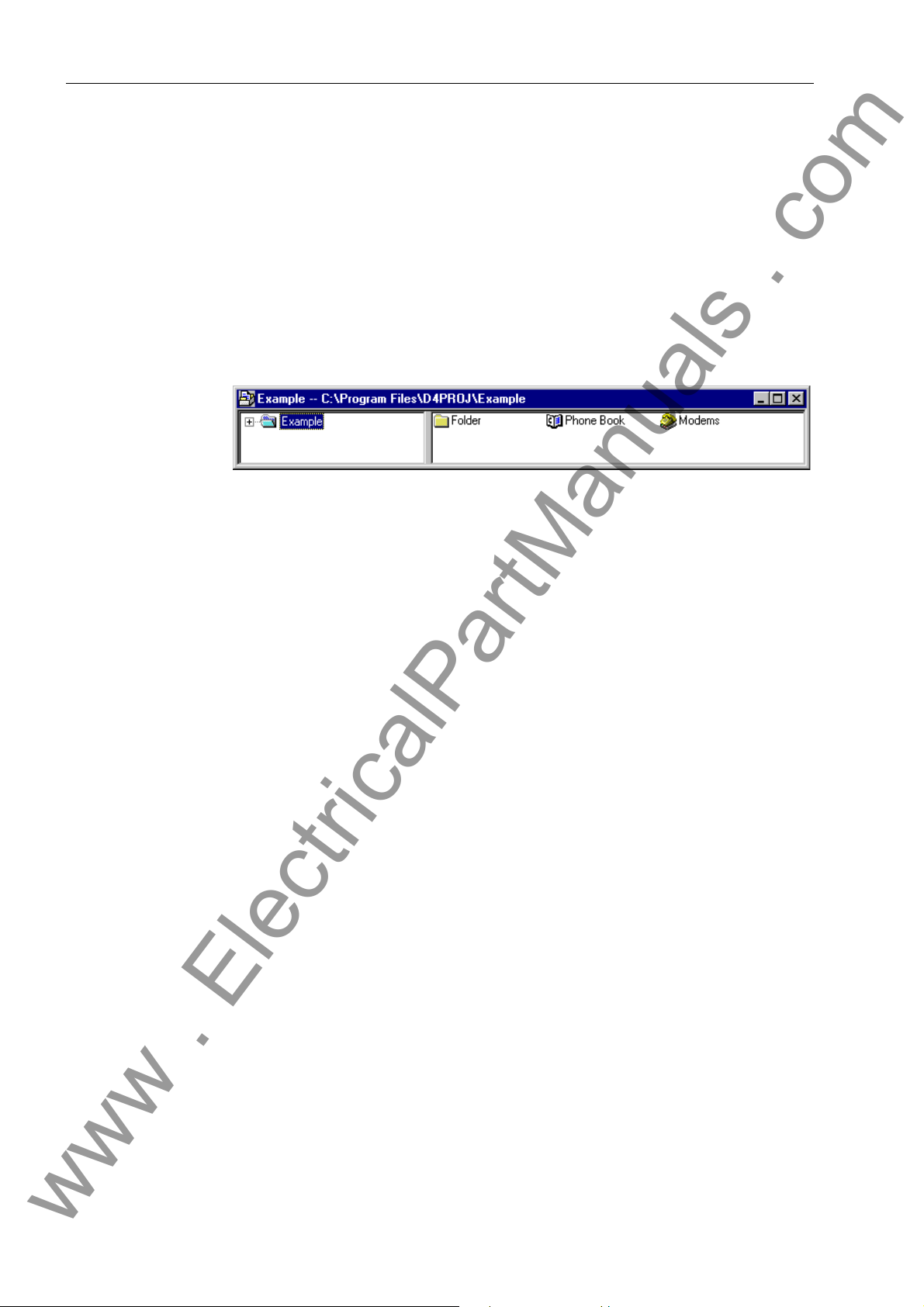
Configuration
www . ElectricalPartManuals . com
4.1 Creating a Project
When configuring with DIGSI you must first create a ne w pr oje ct.
To create a new project you must:
Start DIGSI Manager.
Open the dialog box File → New.
Specify the project name and its filing location.
The project window will open upon that.
Figure 4-1 Project window after the creation of a new project
46
7SS52 V4 Manual
C53000-G1176-C182-3
Page 63
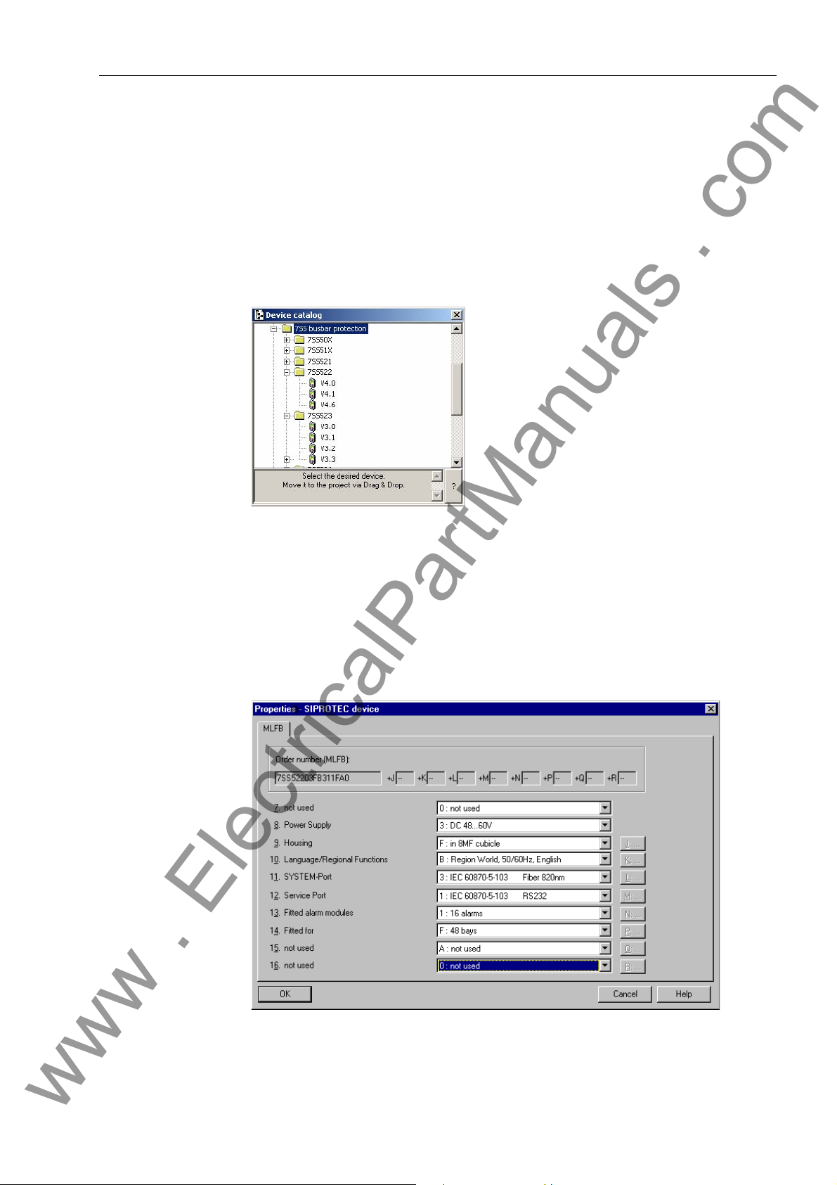
4.2 Inserting Central Unit / Bay Units
www . ElectricalPartManuals . com
In the next step you will insert the central unit and the bay units into the structure of
the project.
To insert the central unit into the project structure you must:
Open the context menu in the project window of DIGSI Manager and open the De-
vice Catalog.
Inserting Central Unit / Bay Units
Figure 4-2 Device Catalog
Switch to the directory 7SS522 in the Device Catalog and drag the object V4.6 for
the version, the left mouse button depressed, to the desired position within the
project structure. After you have released the left mouse button, the dialog box
Properties - SIPROTEC 4 device opens with the tab MLFB. In this tab you can
specify the model of the central unit by selecting the corresponding order number
(MLFB).
Figure 4-3 Dialog box Properties - SIPROTEC 4 device, Tab MLFB
7SS52 V4 Manual
C53000-G1176-C182-3
47
Page 64

Configuration
www . ElectricalPartManuals . com
To insert the bay units into the project structure you must:
Switch to the directory 7SS523 or 7SS525 in the Device Catalog and drag the ob-
ject V3.3 for the version, the left mouse button depressed, to the desired position
within the project structure. This object represents a bay unit. After you have re-
leased the left mouse button, the dialog box Properties - SIPROTEC 3 device
opens with the tab MLFB. In this tab you can specify the model of the bay unit by
selecting the corresponding order number (MLFB). Repeat the procedure until yo u
have inserted all desired bay units into the project structure.
48
7SS52 V4 Manual
C53000-G1176-C182-3
Page 65

4.3 Plant Configuration
www . ElectricalPartManuals . com
In the last section you have created central units and bay units in DIGSI M anager. This
will be the basis for you to configure the substation in the next step . The DIGSI Plan t
Configuration is used for the configuration.
The DIGSI Plant Configuration is a tool which enables you to compile all information
items required by the central unit. First you will create a graphic model of the substation. You do so by drawing busbars and lines in a chart and add isolator switches, circuit breakers and transformers. Afterwards you will assign the individual components
to bays and bay units via dialog boxes. Your entries will be saved in the setting group
and together with it they are transmitted to the central unit (see Chapter 4.8, pag e 89).
In the next step you will assign the bay units you have created in the DIGSI Plant Configuration to the bay units created in the Device Manager (see Chapter 4.5, page 71).
4.3.1 How to Proceed
The next paragraphs will depict the basic procedure by the example of the configuration of a double busbar with bus coupler.
Plant Configuration
In order to draw and parameterize the substation you must:
Start the DIGSI Plant Configuration (Chapter 4.3.2, page 50).
Note
Standard bays such as bus couplers and feeder bays are already available as Typicals. You can find Typicals and Templates in the folder SSTypicals. The DIGSI Plant
Configuration interprets the data correctly.
Insert Typicals anywhere you need them in the chart (Chapter 4.3.9, page 62).
Draw the required busbars and name them (Chapter 4.3.3, page 52).
Insert bay names to define the required bays (Chapter 4.3.4, page 54).
Insert dynamic elements of the libraries into the substation chart (Chapter 4.3.5,
page 56).
Link the dynamic elements with the busbars. Use lines and connections for this pur-
pose (Chapter 4.3.6, page 58).
Insert static text e.g., for comments (Chapter 4.3.8, page 61).
Create Typicals for frequently used substation components and insert them into
the chart where needed (Chapter 4.3.9, page 62).
Save the substation chart and exit the DIGSI Plant Configuration (Chapter 4.3.10,
page 62).
We will illustrate the configuration by the example of a double busbar with bus coupler.
7SS52 V4 Manual
C53000-G1176-C182-3
49
Page 66

Configuration
www . ElectricalPartManuals . com
4.3.2 Starting the Plant Configuration
To start the DIGSI Plant configuration you must:
Select the central unit 7SS522 in the project window of DIGSI Manager and ope n
the context menu via right mouse click. Apply the command Open object. The
Open device dialog box opens. You can also open the dialog box by double-click-
ing the central unit 7SS522.
Figure 4-4 Open Device dialog box
Select the connection type and confirm with OK. The DIGSI Device Configuration
opens.
Unfold the directory Settings in the function selection of the DIGSI Device Config-
uration and select the object Substation configuration.
Figure 4-5 Start screen of the DIGSI De vice Configuration
Right-click the object to open the context menu and apply the command
Open object. The DIGSI Plant Configuration opens. You can also open the DIGSI
Plant Configuration by double-clicking the obje ct Substation configuration.
50
7SS52 V4 Manual
C53000-G1176-C182-3
Page 67

Plant Configuration
www . ElectricalPartManuals . com
Note
The Plant Configuration and the Plant Visualization cannot run simultaneously. Close
the Plant Visualization before you start the Plant Configuration.
Figure 4-6 Start screen of the DIGSI Plant Configuration
Note
For a detailed instruction on how to use the DIGSI Plan t Configuration, please refer to
the corresponding on-line help. The following paragraphs describe the basic method
for drawing and parameterizing a substation.
7SS52 V4 Manual
C53000-G1176-C182-3
51
Page 68

Configuration
www . ElectricalPartManuals . com
4.3.3 Drawing Busbars
Busbars can be drawn into the substation chart in vertical or horizontal direction. A
busbar can also be a combination of vertical and horizontal lines. For this purpose
place the starting point of the busbar you want to draw on the e nd point of an e xisting
busbar. The two lines will merge to form a single busbar. Thus you can draw e.g., Ushaped busbars. Busbars can also be T-shaped. For this purpose place the starting
point of the busbar you want to draw on an already existing busbar. Again the two lines
will merge to form a single busbar. A connection will be inserted automatically in the
junction point of the two busbars.
Note
You can use templates for drawing a new chart. Some templates are installe d on your
computer together with DIGSI. You can also save your own charts as templa tes. You
will find further information in the on-line help of the DIGSI Plant Configuration.
To draw a busbar you must:
Click Tools → Draw busbar. Alternatively, you can click the button on the tool-
bar.
Click the place in the chart which is to be the starting point of the busbar. Hold the
mouse button pressed down.
Draw the mouse pointer, the mouse button depressed, to the position that will mark
the end point of the busbar. Release the mouse button.
To modify the length of a busbar you must:
Click Tools →Select on the menu bar. Alternatively, you can click the button on
the toolbar.
Click on the starting point or on the end point of the corresponding busbar and hold
the mouse button depressed.
Move the mouse pointer, the mouse button depressed, in horizontal or vertical di-
rection depending on the orientation of the busbar. Release the mouse button.
Note
You delete a busbar by making its starting point and end point coincident. You can
thus also erase busbar segments that are open at one end.
52
7SS52 V4 Manual
C53000-G1176-C182-3
Page 69

Plant Configuration
www . ElectricalPartManuals . com
Figure 4-7 DIGSI Plant Configuration, Drawing busbars - Example
To name the busbar you must:
Right-click the busbar. Click Object properties in the context menu. The dialog box
Object Properties - Busbar opens.
Figure 4-8 Dialog box Object Properties - Busbar
Enter a busbar name of not more than 4 characters into the box Name short. This
name will be used to characterize the associated information in the Configuration
Matrix.
7SS52 V4 Manual
C53000-G1176-C182-3
53
Page 70

Configuration
www . ElectricalPartManuals . com
Select one of the 12 busbar sections (BB01 to BB12) or bus cou pler sections (TB01
Click Select to choose the on-line colour of the busbar. The Plant Visualization will
Click OK to apply the settings and to close the dialog box.
Bus coupler zones are bus zones which are used exclusively for connecting bus zones
and which have no feeder bays. In most cases they occur in connection with bus couplers. An example is given in Figure 4-16, page 66 (BS1, BS2).
4.3.4 Defining Bays
Isolators, transformers and circuit breakers must be assigned to a certain bay. A bay
in the substation chart is represented by a bay name. First you insert a wildcard for the
bay name. Next you specify a short name and a long name for the bay name.
Enter a busbar name of not more than 8 characters into the box Name long. This
name will be displayed as movable text within the chart. The long name will also
show in the measured value boxes of the busbar.
to TB12) from the box Busbar section.
show the attachment of the feeders and measuring systems to the corresponding
busbar in the colour you specify here.
To insert a wildcard for the bay name you must:
Click Tools → Insert Bay Name on the menu bar. Alternatively, you can click the
button on the toolbar.
Click the position on the substation chart where you wish to insert the bay name. A
wildcard in the form of an asterisk is inserted. Click on the desired positions to insert
further wildcards for bay names.
Note
After you have released the mouse button, the program verifies whether the wildcard
superposes other elements. If this is the case, you will receive a corresponding message and the wildcard will not be inserted into the substation chart.
To specify the short text and long text for a bay name you must:
Right-click the wildcard in question. Click Object properties in the context menu.
Or you can double-click the wildcard. Both methods will open the dialog box Object
properties - Bay Name.
Figure 4-9 Dialog box Object Properties - Bay Name
54
7SS52 V4 Manual
C53000-G1176-C182-3
Page 71

Plant Configuration
www . ElectricalPartManuals . com
Enter a bay name of not more than 4 characters into the box Short text. This name
will be used to characterize the associated information in the Configuration Matrix.
Enter a bay name of not more than eight characters into the box Long text. This
name will be displayed as movable text within the chart of the substation. The long
text will also be displayed in the measured value box of a transformer which is assigned to that bay. As you can give identical names to different bays, each long text
is complemented by an automatically assigned number.
Click OK to apply the settings and to close the dialog box.
Figure 4-10 DIGSI Plant Configuration, Defining bays - Example
7SS52 V4 Manual
C53000-G1176-C182-3
55
Page 72

Configuration
www . ElectricalPartManuals . com
4.3.5 Inserting Dynamic Elements
Static and dynamic elements are inserted into the chart from libraries. Dynamic elements such as isolators, circuit breakers and transformers usually have several possible states. Each state is represented by a separate symbol.
Static and dynamic elements are filed in different libraries. The following three libraries
exist: DIN, SIPROTEC and User-defined.
To insert a dynamic library element you must:
Open the dialog box Select Library via the menu item Library > Select Library
and select a dynamic library.
Select the element in the library you wish to insert in the substation chart.
Click the position on the substation chart where you wish to insert the element. The
element you have selected in the library will be pasted in the specified location. To
insert additional elements of the same type into the chart, click the places where
you wish to insert them.
Note
After you have released the mouse button, the program verifies whether the ele ment
superposes other dynamic elements. If this is the case, you will receive a corresponding message and the new element will not be inserted into the substation chart.
Figure 4-11 DIGSI Plant Configuration - Inserting dynamic elements - Example
56
7SS52 V4 Manual
C53000-G1176-C182-3
Page 73

Plant Configuration
www . ElectricalPartManuals . com
Isolators, transformers and circuit breakers have properties whose values must be set
individually.
To specify the property values of a dynamic element you must:
Right-click a single element. Click Object properties in the context menu. A prop-
erties dialog opens for the selected element.
Make the required settings.
Click OK to apply the settings and to close the dialog box.
Note
Further information on setting the element property values can be found in the on-line
help of the DIGSI Plant Configuration.
7SS52 V4 Manual
C53000-G1176-C182-3
57
Page 74

Configuration
www . ElectricalPartManuals . com
4.3.6 Connecting Dynamic Elements to the Busbars
Dynamic elements can be connected to busbars via lines.
4.3.6.1 Inserting Lines
Lines can connect elements such as isolators, transformers, circuit breakers an d lines
with each other and to a busbar. Lines can be drawn into the substation chart in vertical or horizontal direction. A line can also be a combination of vertical and horizontal
lines. For this purpose you place the starting point of the line you want to draw on the
end point of an existing line. Unlike busbars the individual line segments cannot be
merged to a single line. They can still be edited individually. Lines may also be linked
in T-shape. For this purpose place the starting point of the line you want to dr aw on an
already existing line. A connection will be inserted automatically in the junction point
of the two lines.
To draw a line you must:
Click Tools → Draw Line. Alternatively, you can click the button on the toolbar.
Click the place in the chart which is to be the starting point of the line. Hold the
mouse button pressed down.
Draw the mouse pointer, the mouse button depressed, to the position that will mark
the end point of the line. Release the mouse button.
To modify the length of a line you must:
Click Tools →Select on the menu bar. Alternatively, you can click the button on
the chart toolbar.
Click on the starting point or on the end point of the corresponding line and hold the
mouse button depressed.
Move the mouse pointer, the mouse button depressed, in horizontal or vertical di-
rection depending on the orientation of the line. Release the mouse button.
Note
A line is deleted by making its starting point and end point coincident.
58
7SS52 V4 Manual
C53000-G1176-C182-3
Page 75
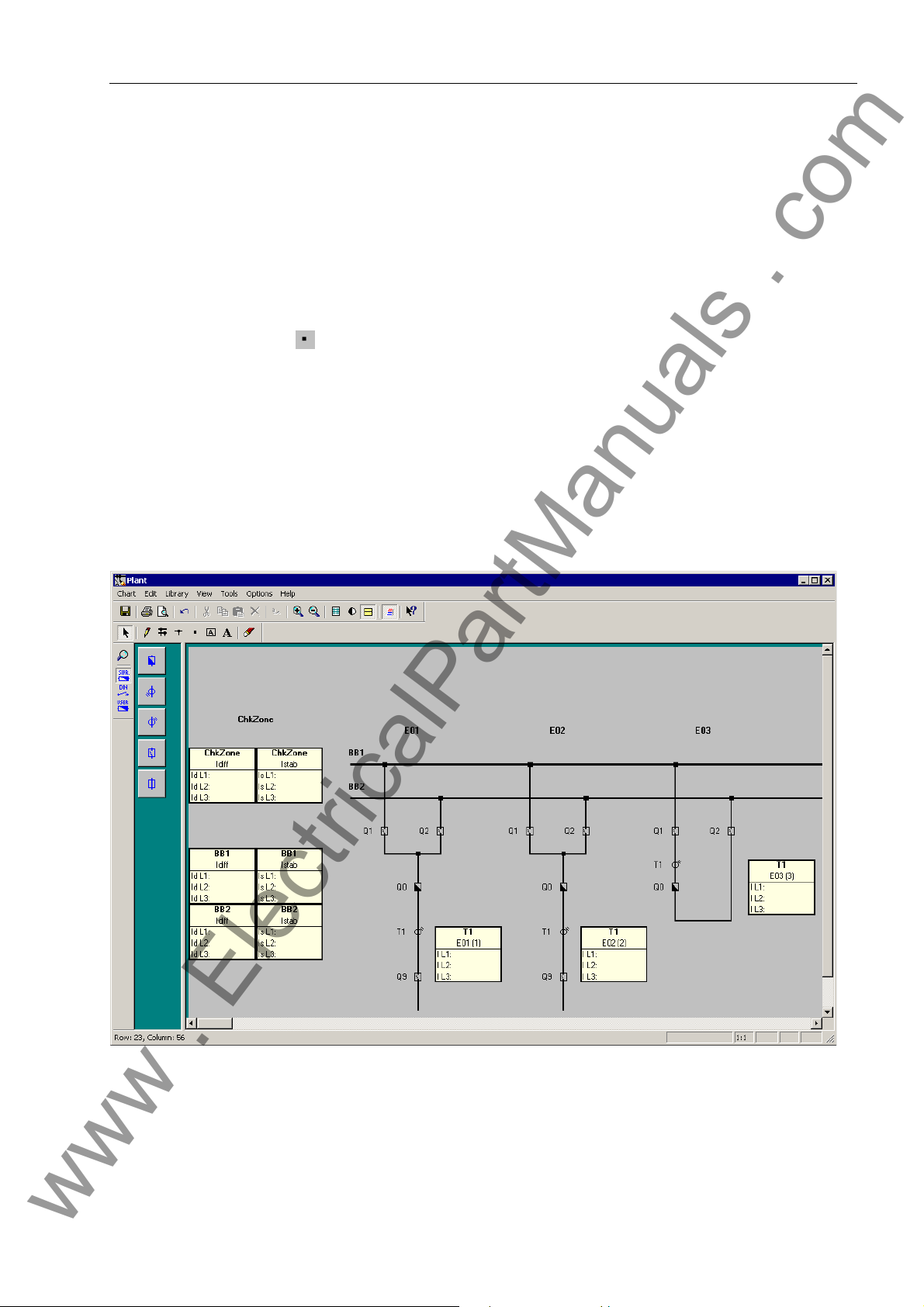
4.3.6.2 Inserting a Connection
www . ElectricalPartManuals . com
Lines or busbars that cross in the chart are not yet connected electrically. To this end
you must insert an additional connection in the junctio n point. Such a co nnection is indicated by a small square. By manually adding a connection each line is separated
into two autonomous lines. When you draw lines and busbars so that they meet as a
T, a connection will be automatically inserted in the junction point. Unlike the manual
insertion an automatically added connection does not split lines and busbars.
To insert a connection you must:
Click Tools → Insert Connection on the menu bar. Alternatively, you can click the
button on the toolbar.
In the chart click on the position of a busbar or line where you wish to insert a con-
nection.
To delete a manually added connection you must:
Draw a new busbar across the connected busbar sections if you want to delete the
connection between two busbars. The connectio n and the busbar on the right-hand
side or the lower of the two busbars is deleted.
Draw a new line across the connected line sections if you want to delete the con-
nection between two lines. The connection and the line on the right-hand side or the
lower of the two lines is deleted.
Plant Configuration
Figure 4-12 DIGSI Plant Configuration - Inserting lines and connections - Example
7SS52 V4 Manual
C53000-G1176-C182-3
59
Page 76

Configuration
www . ElectricalPartManuals . com
4.3.7 Normalized Current
Normally, the configuration tool determines the so-called normalized current
automatically by searching for the current transformer with th e highest primary
nominal current when you exit the configuration. All parameters with the dimension l/
lno refer to this reference value. You can select any other normalized curren t in the
configuration tool under Tools → Set Reference Value. When exiting the
configuration you can choose between the calcula te d value or th e on e you ha ve
defined in the dialog Specifying a reference Value (Figure 4-13, page 60). A lower
value allows you for example to increase the sensitivity of the differential current
supervision because it has a lower setting limit of 5% l/lno.
The normalized current which you define here may not exceed 5 times the value o f the
configured maximum rated transformer current.
Figure 4-13 Select Reference Value
60
7SS52 V4 Manual
C53000-G1176-C182-3
Page 77
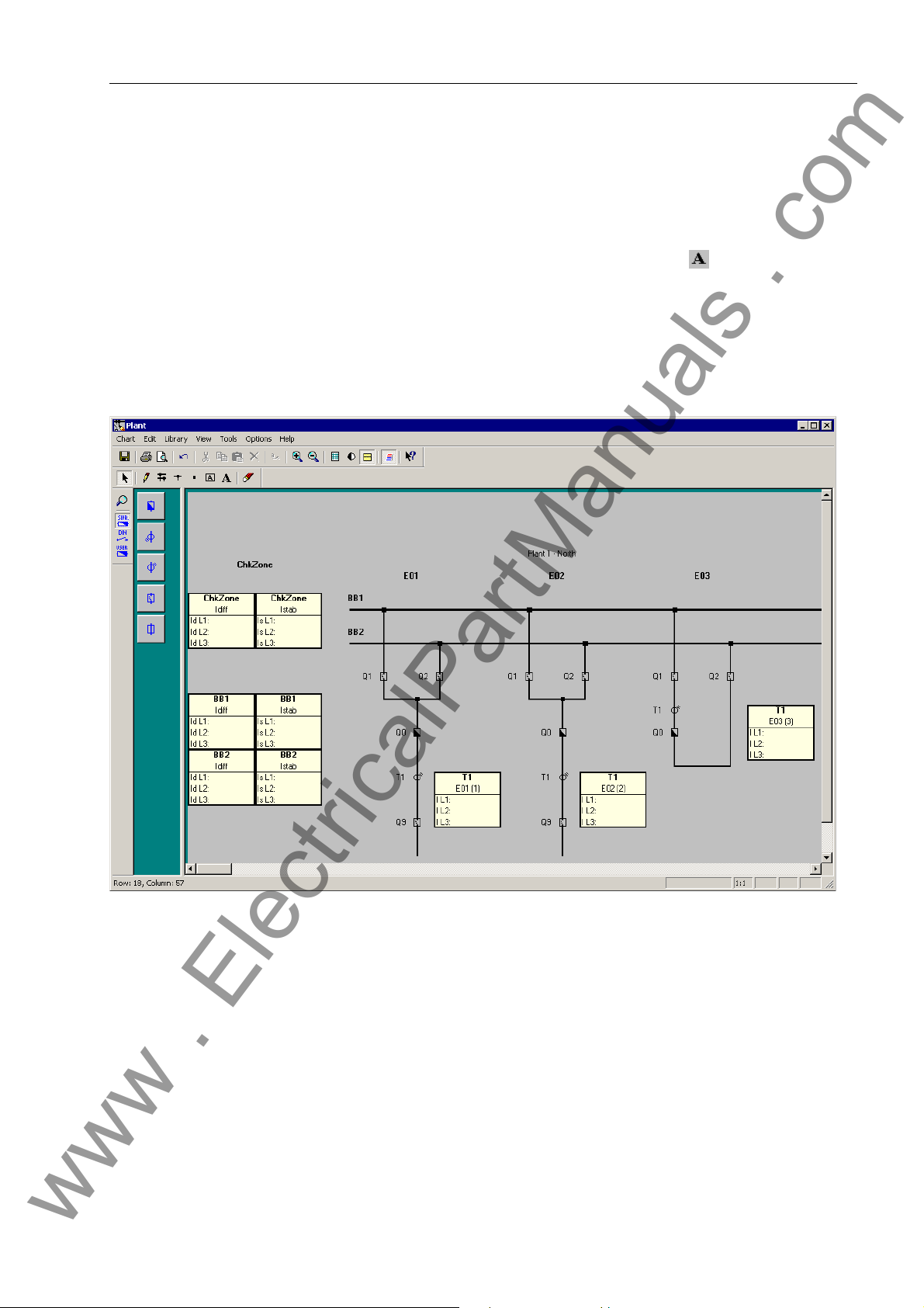
4.3.8 Inserting Static Text
www . ElectricalPartManuals . com
You can use static text to give additional short information within the chart. A static text
may be composed of not more than twenty characters.
To insert static text you must:
Click Tools→Insert Text. Alternatively, you can click the button on the chart
toolbar.
Click the position on the substation chart where you wish to insert the text. A text
input box opens.
Write the desired text into this box. That finished click the green check mark to the
right of the text box. The text will be placed left-aligned to the selected insertion
point.
Plant Configuration
Figure 4-14 DIGSI Plant Configuration - Inserting static text - Example
7SS52 V4 Manual
C53000-G1176-C182-3
61
Page 78

Configuration
www . ElectricalPartManuals . com
4.3.9 Creating and Inserting Typicals.
An arrangement of different elements in the substation chart can be saved as a socalled Typical. This Typical may then be inserted anywhere else in the substation
chart or into other charts.
Note
Unlike a Typical a Template represents an entire substation chart which may be composed of Typicals. Templates may also be saved for reuse.
To save elements as Typical you must:
Select all elements in the chart you wish to save together as Typical.
Click Edit →Save Graphic/Typical as on the menu bar. The Save as dialog box
opens.
Enter a name for the Typical file. A Typical file has the extension .sst.
Select the location where you want to save the Typical file.
Click OK to apply the settings and to close the dialog box. The elements are saved
to a file in the form of a Typical.
To insert a Typical you must:
Click Edit →Insert Graphic/Typical from on the menu bar. The Open dialog box
pops up.
Select the drive of the Typical file from the Browse drop-down list box.
Select a folder in the drop-down list box. You will find the supplied template files in
the folder SSTypicals.
All available files with the extension .sst are displayed in the box. Select the name
of the Typical file you wish to open.
Click OK to open the Typical file and to close the dialog box.
Left-click into the chart to insert the Typical.
4.3.10 Saving the Substation Chart
You must explicitly save the modifications you have made to a chart.
To save the changes in the active chart you must:
Click Chart →Save on the menu bar.
Alternatively, you can click the button on the Standard toolbar.
62
7SS52 V4 Manual
C53000-G1176-C182-3
Page 79

4.4 Configuration Notes
www . ElectricalPartManuals . com
The 7SS52 V4 can be applied for the protection of busbar configurations with quintuple busbars as a maximum and up to 48 feeders.
• When configuring the up to 12 busbar sections and 12 bus coupler sections you will
determine the description, busbar section number an d colour for the individua l busbar sections (BB01 to BB12) or bus coupler sections (TB01 to TB12).
The evaluation report allows you to check the parameter assignments of the plant
configuration (see Figure 4-37, page 89).
Note
A feeder bay must include at least one isolator, one current tr ansformer and one circuit
breaker (if end fault protection is used).
A coupler must include at least two isolators and one current transformer.
• 2-bay bus couplers must be parameterized to bay units with successive numbers
(Figure 7-1, page 260).
Configuration Notes
• In 2-bay-couplers you can configure one or two current transforme rs
(Chapter 7.1.3.2, page 259 and Chapter 7.1.3.3, page 259).
• For each bay unit you may configure not more than one transfer bus isolator.
Transfer bus operation is only possible with transfer bus isolators of different bay
units.
• Only switchgear or current transformers of the same ba y may be assigned to a b ay
unit. Except sectionalising isolators.
Note
Gaps in the configuration (e.g. reserve bays) are allowed.
An example of a triple busbar with transfer b usbars is shown in Figure 4-15, page 64.
The corresponding configuration data are collected in Table 4-1, page 65.
An example of a double busbar with a combination busbar is shown in Figure 4-16,
page 66. The corresponding configuration data are collected in Table 4-2, page 66.
7SS52 V4 Manual
C53000-G1176-C182-3
63
Page 80

Configuration
www . ElectricalPartManuals . com
Figure 4-15 Triple busbar with transfer busbar
1a) inside current transformer (referred to Q7), in the direction of the busbar (ref erred to Q0)
1b) inside current transformer (referred to Q7), in the direction of the line (referred to Q0)
2) line inside current transformer (referred to Q7)
64
7SS52 V4 Manual
C53000-G1176-C182-3
Page 81

Table 4-1 Configuration for a triple busbar with transfer busbar
www . ElectricalPartManuals . com
Bay: (XX) Bay: Type CT LOC
01 Feeder bay 1a) Bus side t. bus
1b) Bus side t. line
2) line side
02 2-bay coupler Bus side t. line
03 2-bay coupler non existent
04 2-bay coupler Bus side t. line
05 2-bay coupler Bus side t. line
06 Section isolator non existent
07 Feeder bay 1a) Bus side t. bus
1b) Bus side t. line
2) line side
Configuration Notes
08 2-bay coupler Bus side t. line
09 2-bay coupler non existent
1a) inside current transformer (referred to Q7), in the direction of the busbar (referred to Q0)
1b) inside current transformer (referred to Q7), in the direction of the line (referred to Q0)
2) line side current transformer (referred to Q7)
7SS52 V4 Manual
C53000-G1176-C182-3
65
Page 82

Configuration
www . ElectricalPartManuals . com
Figure 4-16 Double busbar with combi-bus
Table 4-2 Configuration of a double busbar with combi-bus
Bay: (xx) Bay Type CT LOC
01 1-bay coupler Bus side t. line
02 Feeder bay line side
03 Feeder bay line side
04 1-bay coupler w/o CB Bus side t. bus
05 Section isolator non existent
06 1-bay coupler Bus side t. bus
07 Feeder bay line side
08 Section isolator non existent
09 1-bay coupler Bus side t. line
10 Section isolator non existent
11 Feeder bay line side
12 Feeder bay line side
66
7SS52 V4 Manual
C53000-G1176-C182-3
Page 83

Configuration Notes
www . ElectricalPartManuals . com
Bay types In the DIGSI Plant Configuration you may configure the feeders as 1-bay-coupler, 2-
bay-coupler, feeder bay or sectionalizer.
Reserve bays Reserve bays may be provided for in the configuration; they may be assigned any
number that corresponds to their actual location. DIGSI configures the corresponding
bay to not existent, if it has been drawn in the Plant Configuration but is not assigned
in the "Bay unit allocation".
Hardware design Depending on the size of the plant, the hardware design of the central unit can be
adapted in steps of 8 connections for bay units.
Station
configuration
Bus couplers For furthe r explanations about conn ection and setting of the bus couple r bays plea se
Isolator Up to 5 isolators can be connected to each bay unit. Transferbus isolators must be
Sectionalizing isolator
One bay unit is allocated to each feeder bay and each sectionalizer. The station configuration can include up to 16 bus couplers and 24 s ec tion a lizers.
Accordingly, bus couplers may be assigned one or two bay units depending on the
number of primary components.
refer to Chapter 7.1.3, page 258.
marked correspondingly in the Object Properties.
For each isolator one auxiliary contact for recognition of the OPEN position and one
auxiliary contact for recognition of the CLOSED position is wired to the bay unit.
The binary inputs BI1 to BI10 of bay unit 7SS523 have default allocations (refer to
Chapter A.15, page 395) which can however be changed. Bay unit 7SS525 with BI1
to BI4.
The isolators in the individual bus zones are assigned via the bus zone number .
Isolators 1 to 5 can be used as sectionalizing isolator too. If the b ay unit has exclusively sectionalizing isolators the type "sectionalizing isolator " is assigned to the bay unit.
A maximum of 24 sectionalizers can be configured per substation.
CTs To include the transfer or combi-bus in the protection system, the CTs in the feeder
bays (Figure 4-16, page 66) must be located on the lin e side, and the pr otection function must be released in PROT TR BUS (5401/CU).
7SS52 V4 Manual
C53000-G1176-C182-3
67
Page 84

Configuration
www . ElectricalPartManuals . com
CT location The DIGSI Plant Configuration evaluates the CT location for the end fault protection
and for stations with transfer busbars. The settings mean in this context:
• busside towards busbar means that the transformer is located between the circuit
breaker and the busbar isolator (Figure 4-15, page 64, 1a)
• busside towards line means that the transformer is located upstream of the feeder
isolator, i.e. between the circuit breaker and the feeder isolator (refer to Figure 415, page 64, 1b)
• line side means that the transformer is located downstream of the feeder isolator
(Figure 4-15, page 64, 2).
For the end fault protection, the position of the current transformer relative to the circuit
breaker is important (position 1 a or 1b and 2 respectively). For the behaviour or the
protection in bypass operation, the position of the current transformer relative to the
transfer busbar isolator is important (position 1a and 1b respectively or 2).
In “2-bay couplers”, CT is only assigned to one b ay unit (Figure 4-17, page 68 and Figure 4-18, page 69).
Figure 4-17 Example for the configuration of a 2-bay coupler with one CT
Bay Bay unit
E01
E02a
E02b
E03
68
BU 1
BU 2
BU 3
BU 4
7SS52 V4 Manual
C53000-G1176-C182-3
Page 85

Configuration Notes
www . ElectricalPartManuals . com
Figure 4-18 Object properties of the transformer T1 from the example given in Figure 4-17,
page 68
Figure 4-19 Example for the configuration of a 2-bay coupler with two CTs
Bay Bay unit
E01
E02a
E02b
E03
E04
Please note the crosswise assignment of the tra n sfo rm e rs .
7SS52 V4 Manual
C53000-G1176-C182-3
BU 1
BU 2
BU 3
BU 4
BU 5
69
Page 86

Configuration
www . ElectricalPartManuals . com
Figure 4-20 Object properties of the transformer from the example given in Figure 4-19, page 69
70
7SS52 V4 Manual
C53000-G1176-C182-3
Page 87

4.5 Assigning Bay Units
www . ElectricalPartManuals . com
In the previous step you have drawn and parameterized your entire substation with the
DIGSI Plant Configuration. Thus you have also configured bay units. Subsequently
you must assign these bay units to the bay units in the Device Manager (see Chapter
4.2, page 47). Then you will be able to open the configured chart of the substation in
the Plant Visualization and there you will see the present changes of the measured
values and switch states. Furthermore, the central unit will not start without the assignment of the bay units.
To assign bay units you must:
Open the folder Settings in the DIGSI Device Configuration and select the fu nction
Bay unit allocation.
Assigning Bay Units
Figure 4-21 DIGSI Device Configuration - The folder Settings
Right-click the object to open the context menu and apply the comman d Open ob-
ject. You can also double-click the function Bay unit allocation. The Bay unit assignment dialog box opens. The left column is a list of all bay units configured with
the DIGSI Plant Configuration.
Figure 4-22 DIGSI Device Configuration - Dialog box for Bay unit assignment
7SS52 V4 Manual
C53000-G1176-C182-3
71
Page 88

Configuration
www . ElectricalPartManuals . com
Assign the created bay units in the right column to the configured b ay units. In each
row of the right column select a bay unit you have created in the Device Manager
from the drop-down list. Bay units that are already assigned will not appear in the
drop-down list. If there are not enough bay units available, you must create new
ones in the device manager (see Chapter 4.2, page 47).
Note
You can print the assignment of the bay units via the menu File → Print. The printout
contains the number (1 to 48), the configured virtual bay unit and the physically existing bay unit created in the Device Manager.
72
7SS52 V4 Manual
C53000-G1176-C182-3
Page 89

4.6 Marshalling
www . ElectricalPartManuals . com
In the previous step you have assigned the configured bay units to the bay units created in the Device Manager.
Next you will allocate information items to the input and output components of 7SS52
V4 such as binary inputs and binary outputs or LEDs. Information items can be indications and measured values.
You will not only determine the allocation itself but also the type of the allocation.
An indication may for example be allocated to an LED in latched or unlatched mode.
Also user-defined logic function can be the source of and the destination for information items. The assignment of information items to sources and destinations is called
marshalling.
4.6.1 Marshalling Information Items of the Central Unit
4.6.1.1 Allocable Information
Marshalling
Binary inputs The D-CPU communication module features 5 binary inputs (BI 1 to 5).
The EAZ input/output module features 7 binary inputs (BI 6 to 12).
The binary inputs are freely allocable. The can be activated with or without voltage.
Note
Allocate the indication “>EF charact.“(FNo. 10478/CU) for the earth fault characteristic to the binary input 1 to 5 since these binary inputs process by 1 to 2 ms faster
than the binary inputs 6 to 12.
Event data and binary input data are pre-allocated (see Table A-22, page 395).
The Chapter A.9, page 373 gives an overview of all possible indications with their func-
tion number (FNo.).
Binary outputs and
LED indicators
The central unit features 16 alarm relays and 32 LED indicators.
Any number of annunciations can be marshalled to a binary output (group annuncia-
tion). The most common group annunciations with their own function number are already available in the system (see Chapter A.11, page 389).
Group annunciations that are not available by default a re created by allocating the different function numbers to a relay and/or to an LED. Existing allocation s may have to
be deleted beforehand.
Each annunciation may be allocated to up to 10 relays or LEDs.
The presetting of the signal relays and of the LEDs is identical upon delivery and can
be looked up in the tables A-23, page 395 and A-24, page 396.
The Chapter A.9, page 373 gives an overview of all possible indications with their func-
tion number (FNo.).
7SS52 V4 Manual
C53000-G1176-C182-3
73
Page 90
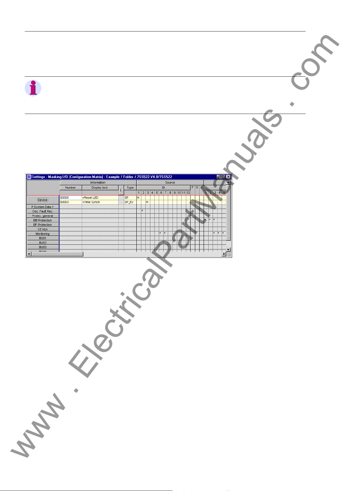
Configuration
www . ElectricalPartManuals . com
4.6.1.2 Marshalling
To marshal information items of the central unit via the Configuration Matrix you must:
Note
Bay units can only be allocated if they have been “i nstanciated” by th e assignment of
library elements (see Chapter 4.3.5, page 56) and by saving the substation chart
Chapter 4.3.10, page 62.
Opening the Configuration Matrix
Figure 4-23 Partial view of the Configuration Matrix
Changing the view Maximize the Configuration Matrix
Open the central unit in DIGSI Manager.
In the function selection of the DIGSI Device Configuration right-click the object
Masking I/O (Configuration Matrix). Click Open object in the context menu.
Or double-click the object. Both methods will open the Configuration Matrix.
74
In the toolbar select the option Indications and commands only from the left of
the two drop-down list boxes.
From the right drop-down list box of th e toolbar select the option Configur ed Infor-
mation.
Click View → Expand → All on the menu bar. Double-click the command button
Long text on the upper bar of the Configuration Matrix to hide this column.
For a detailed description, please refer to the SIPROTEC System Description /1/, and
to the DIGSI on-line help.
Information of the type Indications and Commands, allocated to one source and /o r
destination, are now displayed depending on the selected filter. You will recognize an
allocation by the character in the intersecting cell of an information ro w and of a source
or destination column. Such characters will be called tags (flags) in the following.
Information items are row-wise comprised to groups. The group is indicated by the
command buttons on the left border of the Configuration Matrix. These command buttons are also called group buttons.
7SS52 V4 Manual
C53000-G1176-C182-3
Page 91

Marshalling
www . ElectricalPartManuals . com
Changing Allocations
Inserting information items
Right-click the cell containing a tag (flag). The context menu shows you all tags with
their meaning which are possible for this combination of the information with the
source or the destination. You will always be offered the tag _ (not configured).
Click this entry in the context menu. The cell is now empty.
To find out whether an allocation is possible, place the mouse pointer on the inter-
secting cell of the information row and the source or destination column. If the
mouse pointer turns into a prohibitive sign, you cannot allocate the information to
the selected destination or source. If the mouse pointer does not change, you can
allocate the information.
The Configuration Matrix contains several predefined information items. They can be
complemented by user-defined information items. You can insert such user-defined
information items into the Configuration Matrix by using the Information Catalog.
Click Insert → Information or View → Information Catalog on the menu bar.
The Information Catalog opens.
7SS52 V4 Manual
C53000-G1176-C182-3
Figure 4-24 Information Catalog
The Information Catalog is basically structured like the tree view of the DIGSI 4 Device
Configuration. Click the plus sign before a folder or double-click a folder symbol to
access a lower hierarchy level within the catalog structure.
Double click in succession on Annunciations and Single Point Indications.
Select the name of an information item.
Drag the information item out of the Information Catalog onto a group button on
the left border of the Configuration Matrix. After you have released the mouse button, a new information item is inserted into the corresponding group.
75
Page 92

Configuration
www . ElectricalPartManuals . com
4.6.2 Marshalling Bay Unit Information
4.6.2.1 Allocable Information
Binary inputs The bay unit 7SS523 features 20 binary inputs which are designated BINARY INPUT
1 to BINARY INPUT 20, bay unit 7SS525 features 10 binary inputs.
The binary inputs are marshalled in the address block 6100/BU. It can be selected for
each binary input function whether it is to operate as make circuit or as break circuit.
A - Make Circuit:
The input acts as a make-contact element meaning that the control voltage at the input
terminal activates the allocated function;
R - Break circuit
The input acts as a break-contact element meaning that the control voltage at the input
terminals resets the function, the function is active witho ut con tro l volt ag e.
Note
Marshalling a logic function to 2 or more binary inputs is not supported (no interconnection). A logic function must be allocated to one binary input.
It is, however, possible to allocate different functions to one binary input.
Table A-26, page 398 and Table A-31, pag e 401 shows the default assignment of the
binary inputs upon delivery.
Chapter A.10, page 383 gives an overview of the allocable input functions with their
function numbers (FNo.).
Signal relay The bay unit has a freely allocable signalling output labelled SIGNAL RELAY 1. The
allocation is made under 6201/BU.
Several logic signalling functions (up to 20) can be marshalled to the signal output.
Indications starting with “>” are the direct checkbacks of the binary inputs and are
identical to them. They appear for as long as the corresponding binary input is active.
The default setting of the signal relay is “Bay o of Serv.” (FNo. 7640/BU).
Chapter A.10, page 383 contains the complete list of all possible signalling function
with the function numbers (FNo.).
LED indicators The bay unit 7SS523 features 18 LEDs for optical event indication.
There are 16 LEDs which are freely allocable labelled LED 1 to LED 16.
It is possible to assign several indications to each LED and also one in dication to sev-
eral LEDs.
Besides the specification of the logic function it is indicated whether the indication is
in latched mode “m” or in unlatchted mode “nm”.
The ex-factory setting of the LEDs can be looked up in Table A-30, page 400.
The default setting of the LEDs 1 to 16 can be displayed u pon selection and can also
be modified.
76
7SS52 V4 Manual
C53000-G1176-C182-3
Page 93
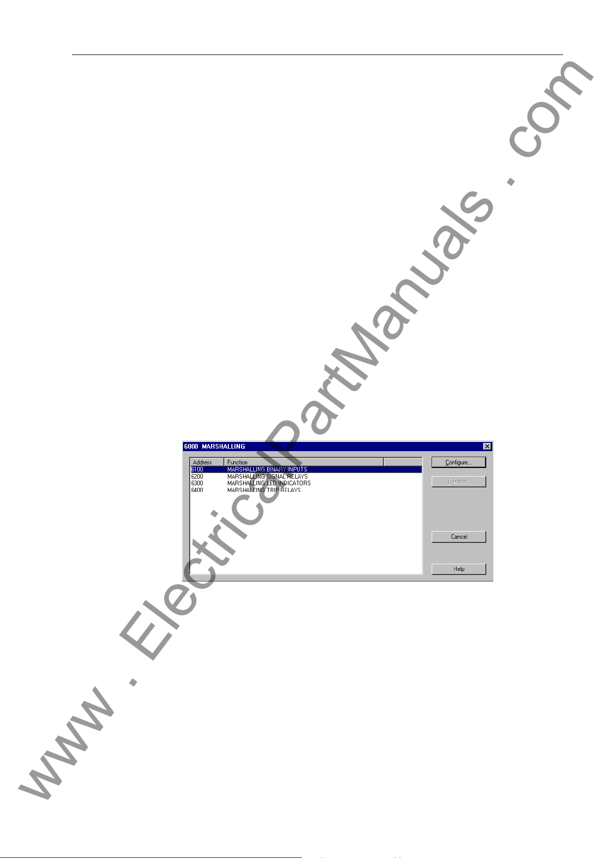
The allocable signalling functions can be looked up in Chapter A.10, page 383 and
www . ElectricalPartManuals . com
match the signal relay functions.
Trip relay The bay unit features 5 trip relays which are labelled TRIP RELAY 1 to 5.
Several functions can be marshalled to each trip relay. Also each logic function can be
allocated to several trip relays.
The trip relays are preferably designed for the output of the TRIP command and of the
transfer trip command. Depending on the plant specification and requirements they
can also be used as additional signal relays.
The default functions of the device upon delivery are comprised in Table A-29, page
399 and Table A-33, page 402.
The functions stated in Chapter A.10, page 383 can also be marshalled to the trip relays.
4.6.2.2 Marshalling
Unlike the central unit the bay units are marshalled via dialog boxes and not via a configuration matrix.
Marshalling
To perform allocations for a bay unit you must:
Open the bay unit in DIGSI Manager.
Open the dialog box Marshalling.
Figure 4-25 Marshalling the bay units - the dialog box Marshalling
In this dialog box you will first select a group of physical components, for example
binary inputs. For this purpose, select the corresponding designation in the Func-
tion column. Subsequently click Configure.... A second dia log box opens. It shows
the names of all individual components of the selected group.
7SS52 V4 Manual
C53000-G1176-C182-3
77
Page 94
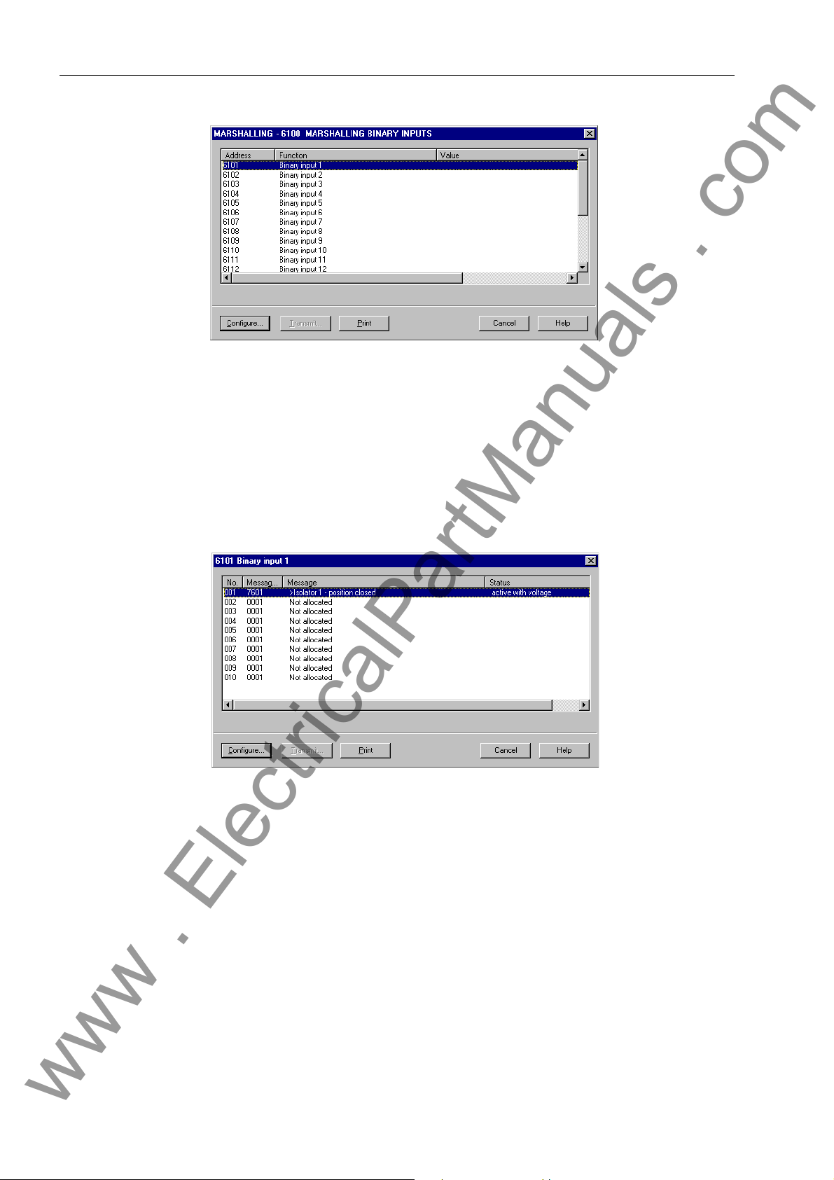
Configuration
www . ElectricalPartManuals . com
Figure 4-26 Marshalling the bay units - the dialog box Marshalling -
Now select the name of the component to which you want to allocate one or several
indications. Subsequently click Configure.... A third dialog box opens. It gives an
overview of how many indications of the selected component can basically be allocated and which indications are already marshalled. The display texts of these indications are shown in the column Status. Those allocating positions that are still
empty are in the same column marked with the entry Not allocated.
Figure 4-27 Marshalling the bay units - the dialog box Binary input 1
To allocate a further message select one of the entries marked Not allocated. To
modify an existing allocation select the display text of the marshalled message.
Subsequently click Configure.... Another dialog box o pen s. It offers you the sele c-
tion of the display texts of all indications which can be marshalled to this component.
78
7SS52 V4 Manual
C53000-G1176-C182-3
Page 95

Marshalling
www . ElectricalPartManuals . com
Figure 4-28 Marshalling the bay units - dialog box 6101 Binary input 1
In the selection box select the display text of the messages you wish to assign to
the selected component. If this component is a binary input or an LED, you must
select an additional indication from the drop-down list box. Subseq uently click OK.
The active dialog box closes and you return to the previous dialog box. The display
of the allocated messages is updated according to your selection.
Repeat the procedure to perform further allocatio ns. When yo u ha ve ma de a ll allo -
cations for the current component click Close. The active dialog box closes and you
return to the previous dialog box.
You can now select a further component if needed. If not, click Close. The active
dialog box closes and you return to the dialog box Marshalling.
You can now select a further component group for con figuration. To fin ish the proc-
ess, click Close. Next you will be prompted whether to save the modified settings
to files. Click Yes to save the data. Click No to discard the changes. To neither save
nor discard the modified settings click Cancel. In this case the dialog box Marshal-
ling remains opened.
7SS52 V4 Manual
C53000-G1176-C182-3
79
Page 96

Configuration
www . ElectricalPartManuals . com
4.7 Settings
After you have used the Configuration Matrix to assign sources and destinations to the
information items, you can configure the settings.
For detailed information on how to parameterize SIPROTEC 4 devices, please read
the SIPROTEC System Description, /1/.
The settings of certain functions (see Chapter 5.10, page 177 and fo llowing sections)
can only be configured for the bay units (PC linked to central unit or bay unit). The procedure is almost identical to the method for SIPROTEC 4 device described below. For
further information on how to parameterize SIPROTEC 3 de vices, please r efer to the
HTML on-line help of the DIGSIDevice Configuration for SIPROTEC 3 devices.
Changing setting
values
Apply settings
To change a setting value you must:
Double-click the object Setting Group. The dialog box Setting Group is displayed.
It gives an overview of protection functions. The individual function designations are
displayed with a function number.
Select for example the entry Power System Data and click Settings. The dialog
box Power System Data opens. It enables you to set all parameters of this function.
Change the value of a text parameter. For this purpose click in the cor responding
box in the column Value. A drop-down list box opens from which you select the new
setting.
Subsequently, change the value of a decimal parameter. For this purpose click in
the corresponding box in the column Value. The mouse cursor s changes into an input cursor. Now you can enter the new numerical value. The unit of a value is assigned automatically.
Click OK. The dialog box Power System Data is closed. Afterwards close the dia-
log box Setting Group by clicking OK.
To apply the changes to the setting values click Apply. This command button is ac-
tive when at least one setting value has been changed. The dialog box remains
opened.
If, however, you click OK, the values are applied and the dialog box closes. In both
cases the values are stored in the memory of the computer. The setting values are
not yet saved to the setting group. If you want to know how to save your settings,
please refer to the device manual DIGSI Device Configuration, Chapter 5.2, page
112.
Transmitting setting values to the
device
80
When you are working Online, the command button DIGSI → Device is active if you
have at least changed one setting value.
Click DIGSI → Device, to transfer the changed settings to 7SS52 V4. The detailed
procedure of transmitting setting values are described in the device manual DIGSI
Device Configuration, Chapter 5.2, page 112.
7SS52 V4 Manual
C53000-G1176-C182-3
Page 97

4.7.1 Serial Ports
www . ElectricalPartManuals . com
Settings
The central unit of 7SS52 V4 features one or more serial ports: one operating interface
integrated in the front panel, also called PC port, and one rear service port and system
port for connection to a control center. Communication via th is port is subject to certain
agreements concerning the device identification, the transmission format and the
transmission rate.
These ports are configured via the DIGSI communication software. Click Settings on
the navigation window. Then click Serial ports in the data window and enter your specific data into the dialog box that opens (Figure 4-29, page 81). Depending on the
model of the device, the dialog box has different tabs with setting options for the corresponding interface parameters which you can access successively by mouse click.
Figure 4-29 DIGSI, settings of the PC port
Serial PC port Indicate on the first tab sheet (Serial port on PC) the communication port of your PC
connected to 7SS52 V4 (COM 1 or COM 2 etc.). You do not have to enter manually
the settings for the data format and for the baudrate. You can take over the values
from the tab Operator interface or, if available, from the tab Service interface. In doing so DIGSI reads out important settings directly from the interface and the corresponding boxes are grayed (see Figure 4-29, page 81). Or you can enter individual
values at the option Independent of device.
PC Port and service
port
7SS52 V4 Manual
C53000-G1176-C182-3
The tab sheets Operator interface and Service interface provide setting options for
the data format, the baudrate and also for the IEC link address and maximum message gap (example given in Figure 4-30, page 82).
81
Page 98

Configuration
www . ElectricalPartManuals . com
Figure 4-30 DIGSI, setting options of the service port − Example
Within an IEC bus, a unique IEC address must be assigned to each SIPROTEC 4 device. A total of 254 IEC addresses are available for each IEC bus. Enter the IEC link
address of this device into the Address box.
The maximum message gap must only be entered if the device is to communicate via
one of the ports by means of a modem. The specified time is the admissible maximum
duration of transmission gaps during message transfer . Transmission gaps occur during modem operation and are caused by data compressio n, fault correction and differing baudrate. If the transmission quality between the modems is good, we recommend
the setting 1.0 s. If modem connections are poor you should increase this value.
High values slow down communication in case of tran sm iss ion err ors . If a PC is connected directly, the Max. message gap can be set to 0.0 s.
Note
Do not use the PC port for the communication via modem!
For the communication via modem use the service port.
Other ports In the other tabs you can enter your specific settings and addresses for device iden ti-
fication or check the values set by default. The device address is used by the control
center to unambiguously identify each device. It must be unique for each device as
otherwise it cannot be assigned in the overall system. For further information on the
port setting, please read the SIPROTEC System Description, /1/.
82
7SS52 V4 Manual
C53000-G1176-C182-3
Page 99

Settings
www . ElectricalPartManuals . com
Idle state of fibre
optic connection
The idle state of fibre optic connection is set to “Light OFF” by default. You can cha nge
the setting for the idle state in the tab of the interface settin gs (see Figur e 4-31, page
83).
Retrieving and
modifying the port
settings via the operator panel
Figure 4-31 Settings for a fibre optic interface
The most important port settings can be read out and some of them also modified via
the operator panel of the actual device. You can access the screen for setting the po rts
from the MAIN MENU via Parameter → Setup/Extras → Serial ports.
Below the heading of the menu (Serial Ports) you can select the PC port, the system
port and the service port via the arrow key . Press the key to access the submenu of each port. The display and the option of parameterizing directly at the device
are identical for the PC port and for the service port. We will take the example of the
PC port (Figure 4-32, page 83).
PC Port 01/04
-------------------- Phys.Addres >254
Baudrate 19200 bauds
Parity 8E1
Gaps 0.0s
Figure 4-32 Reading and setting the PC port via the operator panel of the device.
The type of the port(s) depends on the device model and variant and may also miss
entirely. While it is possible to modify the data of the PC port and th e service port at
the device, the data of the system port(s) can only be read out at the device. In addition
to the parameters already mentioned for the PC port and the se rvice port, the idle state
for fibre optic connection can be read out her e (see Fi gure 4 -33, page 8 4). In case of
a wired interface you will read “not existent” here.
7SS52 V4 Manual
C53000-G1176-C182-3
83
Page 100

Configuration
www . ElectricalPartManuals . com
PC Port 01/02
------------------->IEC60870–5–103 –> 1
Figure 4-33 Reading out the setting values of the IEC 60870 port in the operator panel of the
device.
Bay units To enable correct communication of the PC and the bay units via the system port,
some interface settings may have to be verified or changed.
To verify or change the settings for the PC port and for the system port you must:
Right-click Configuration in the list view. Click Configure in the context menu. You
can also double-click Configuration. Both methods will open the dialog box Operating System Configuration.
In the column Function select the entry PC AND SYSTEM INTERFACES. Subse-
quently click Configure. A second dialog box opens It shows the names of all parameters together with an address and the currently set value.
IEC 60870–5–103
------------------->Phys.Address 254
>Baudrate 9600 bauds
Parity 8E1
Gaps 0.0s
OFF-Sig. Light OFF
Select a parameter to change its value and then click Configure. A third dialog box
opens It offers you possible values for the selected parameter.
Select the desired value. Subsequently click OK. The curren t dialog box closes and
you return to the previous dialog box. The display in the column Value is updated
according to your selection.
Repeat the procedure for further parameters. Click Close to finish the procedure.
The current dialog box closes and you return to the dia log bo x Operating System
Configuration.
Click Close. Next you will be prompted whether to save the modified settings to
files. Click Yes to save the data. Click No to discard the changes. To neither save
nor discard the modified settings click Cancel. In this case the dialog box Operat-
ing System Configuration remains opened.
Note
If you change the device address of a bay unit, you must reassign the bay unit in the
DIGSI Device Manager (see Chapter 4.5, page 71) to enable the configured substation chart to be opened in the Plant Visualization and there to display the latest chang es of the measured values and switch states.
84
7SS52 V4 Manual
C53000-G1176-C182-3
 Loading...