

Siemens SIPROTEC 7SK80 User Manual

SIPROTEC
Preface
Contents
Introduction 1
Functions 2
Motor Protection
7SK80
V4.6
Manual
Mounting and Commissioning 3
Technical Data 4
Appendix A
Literature
Glossary
Index
E50417-G1140-C344-A4

Note
For safety purposes, please note instructions and warnings in the Preface.
Disclaimer of Liability
We have checked the contents of this manual against the hardware
and software described. However, deviations from the description
cannot be completely ruled out, so that no liability can be accepted
for any errors or omissions contained in the information given.
The information given in this document is reviewed regularly and
any necessary corrections will be included in subsequent editions.
Copyright
Copyright © Siemens AG 2010. All rights reserved.
Dissemination or reproduction of this document, or evaluation and
communication of its contents, is not authorized except where expressly permitted. Violations are liable for damages. All rights reserved, particularly for the purposes of patent application or trademark registration.
We appreciate any suggested improvements.
We reserve the right to make technical improvements without
notice.
Document version V04.03.01.
Release date 08.2010
Registered Trademarks
SIPROTEC, SINAUT, SICAM and DIGSI are registered trademarks
of Siemens AG. Other designations in this manual might be trademarks whose use by third parties for their own purposes would infringe the rights of the owner.
Siemens Aktiengesellschaft Order no.: E50417-G1140-C344-A4

Preface
Purpose of this Manual
This manual describes the functions, operation, installation, and commissioning of 7SK80 devices. In particular,
one will find:
• Information regarding the configuration of the scope of the device and a description of the device functions
and settings → Chapter 2;
• Instructions for Installation and Commissioning → Chapter 3;
• Compilation of the Technical Data → Chapter 4;
• As well as a compilation of the most significant data for advanced users → Appendix A.
General information with regard to design, configuration, and operation of SIPROTEC 4 devices are set out in
the SIPROTEC 4 System Description /1/.
T arget Audience
Protection engineers, commissioning engineers, personnel concerned with adjustment, checking, and service
of selective protective equipment, automatic and control facilities, and personnel of electrical facilities and
power plants.
Applicability of this Manual
This manual applies to: SIPROTEC 4 Multifunctional Protection Device with Motor Protection 7SK80; Firmware
Version V4.6
Indication of Conformity
This product complies with the directive of the Council of the European Communities on the
approximation of the laws of the Member States relating to electromagnetic compatibility (EMC
Council Directive 2004/108/EC) and concerning electrical equipment for use within specified
voltage limits (Low-voltage Directive 2006/95 EC).
This conformity is proved by tests conducted by Siemens AG in accordance with the Council
Directive in agreement with the generic standards EN 61000-6-2 and EN 61000-6-4 for EMC
directive, and with the standard EN 60255-27 for the low-voltage directive.
The device has been designed and produced for industrial use.
The product conforms with the international standards of the series IEC 60255 and the German
standard VDE 0435.
SIPROTEC, 7SK80, Manual
E50417-G1140-C344-A4, Release date 08.2010
3

Preface
Additional St andards
Additional Support
Should further information on the System SIPROTEC 4 be desired or should particular problems arise which
are not covered sufficiently for the purchaser's purpose, the matter should be referred to the local Siemens representative.
Our Customer Support Center provides a 24-hour service.
Telephone: +49 (180) 524-7000
Fax: +49 (180) 524-2471
e-mail: support.energy@siemens.com
IEEE C37.90 (see Chapter 4 "Technical Data")
This product is UL-certfied with the values as stated in the Technical Data.
file E194016
Training Courses
Enquiries regarding individual training courses should be addressed to our Training Center:
Siemens AG
Siemens Power Academy TD
Humboldt Street 59
90459 Nuremberg
Telephone: +49 (911) 433-7005
Fax: +49 (911) 433-7929
Internet: www.siemens.com/power-academy-td
4
E50417-G1140-C344-A4, Release date 08.2010
SIPROTEC, 7SK80, Manual
Safety Information
This manual does not constitute a complete index of all required safety measures for operation of the equipment (module, device), as special operational conditions may require additional measures. However, it comprises important information that should be noted for purposes of personal safety as well as avoiding material
damage. Information that is highlighted by means of a warning triangle and according to the degree of danger,
is illustrated as follows.
DANGER!
Danger indicates that death, severe personal injury or substantial material damage will result if proper precautions are not taken.
WARNING!
indicates that death, severe personal injury or substantial property damage may result if proper precautions are
not taken.
Caution!
indicates that minor personal injury or property damage may result if proper precautions are not taken. This
particularly applies to damage to or within the device itself and consequential damage thereof.
Preface
Note
indicates information on the device, handling of the device, or the respective part of the instruction manual
which is important to be noted.
SIPROTEC, 7SK80, Manual
E50417-G1140-C344-A4, Release date 08.2010
5

Preface
WARNING!
Qualified Personnel
Commissioning and operation of the equipment (module, device) as set out in this manual may only be carried
out by qualified personnel. Qualified personnel in terms of the technical safety information as set out in this
manual are persons who are authorized to commission, activate, to ground and to designate devices, systems
and electrical circuits in accordance with the safety standards.
Use as prescribed
The operational equipment (device, module) may only be used for such applications as set out in the catalogue
and the technical description, and only in combination with third-party equipment recommended or approved
by Siemens.
The successful and safe operation of the device is dependent on proper handling, storage, installation, operation, and maintenance.
When operating an electrical equipment, certain parts of the device are inevitably subject to dangerous voltage.
Severe personal injury or property damage may result if the device is not handled properly.
Before any connections are made, the device must be grounded to the ground terminal.
All circuit components connected to the voltage supply may be subject to dangerous voltage.
Dangerous voltage may be present in the device even after the power supply voltage has been removed (capacitors can still be charged).
Operational equipment with exposed current transformer circuits may not be operated.
The limit values as specified in this manual or in the operating instructions may not be exceeded. This aspect
must also be observed during testing and commissioning.
6
E50417-G1140-C344-A4, Release date 08.2010
SIPROTEC, 7SK80, Manual
T ypographic and Symbol Conventions
The following text formats are used when literal information from the device or to the device appear in the text
flow:
Parameter Names
Designators of configuration or function parameters which may appear word-for-word in the display of the
device or on the screen of a personal computer (with operation software DIGSI), are marked in bold letters in
monospace type style. The same applies to the titles of menus.
1234A
Parameter addresses have the same character style as parameter names. Parameter addresses contain the
suffix A in the overview tables if the parameter can only be set in DIGSI via the option Display additional set-
tings.
Parameter Options
Possible settings of text parameters, which may appear word-for-word in the display of the device or on the
screen of a personal computer (with operation software DIGSI), are additionally written in italics. The same
applies to the options of the menus.
„Messages“
Designators for information, which may be output by the relay or required from other devices or from the switch
gear, are marked in a monospace type style in quotation marks.
Preface
Deviations may be permitted in drawings and tables when the type of designator can be obviously derived from
the illustration.
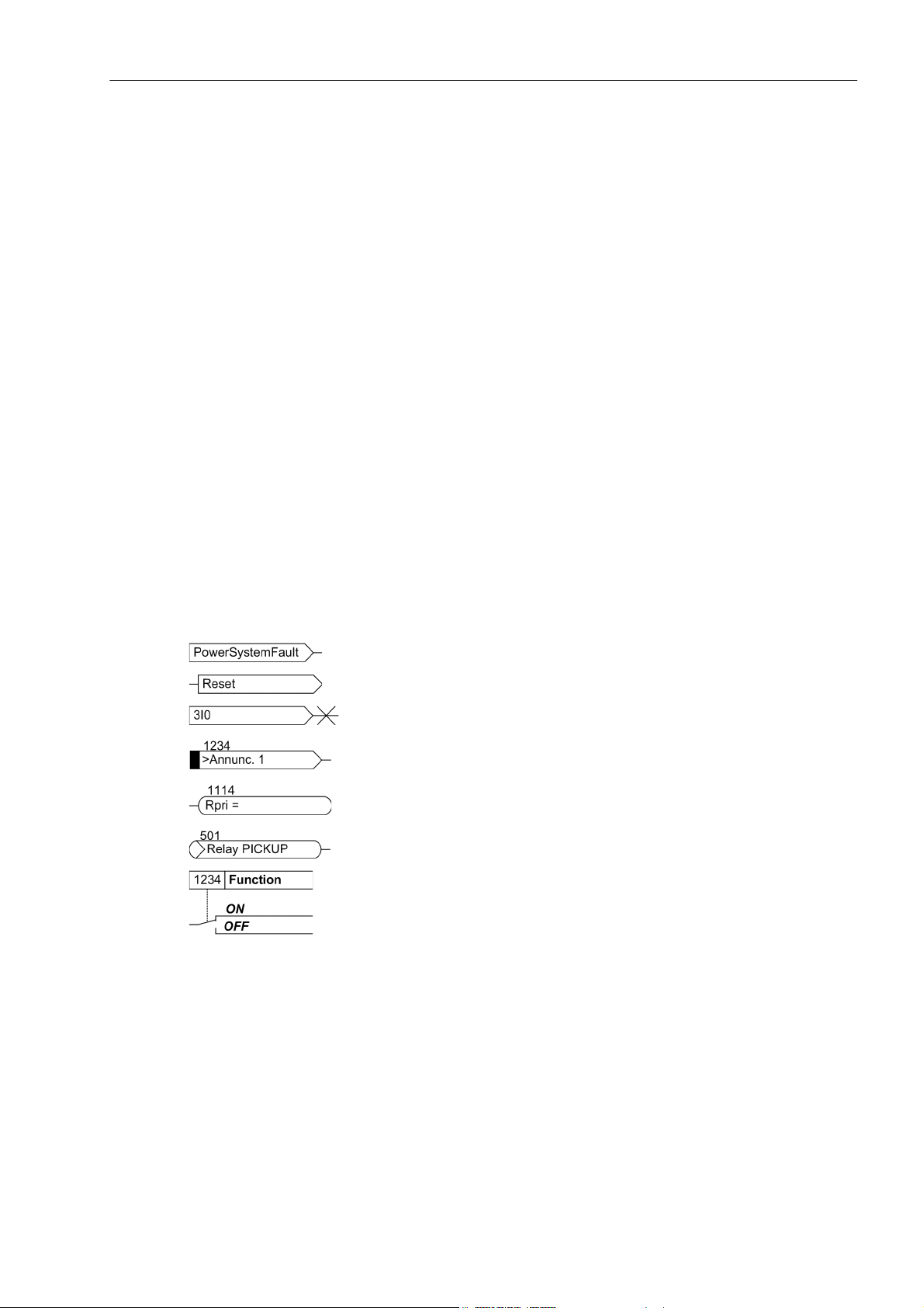
The following symbols are used in drawings:
Device-internal logical input signal
Device-internal logical output signal
Internal input signal of an analog quantity
External binary input signal with number (binary input,
input indication)
External binary input signal with number
(example of a value indication)
External binary output signal with number (device indication) used as
input signal
Example of a parameter switch designated FUNCTION with address
1234 and the possible settings ON and OFF
SIPROTEC, 7SK80, Manual
E50417-G1140-C344-A4, Release date 08.2010
7
Preface
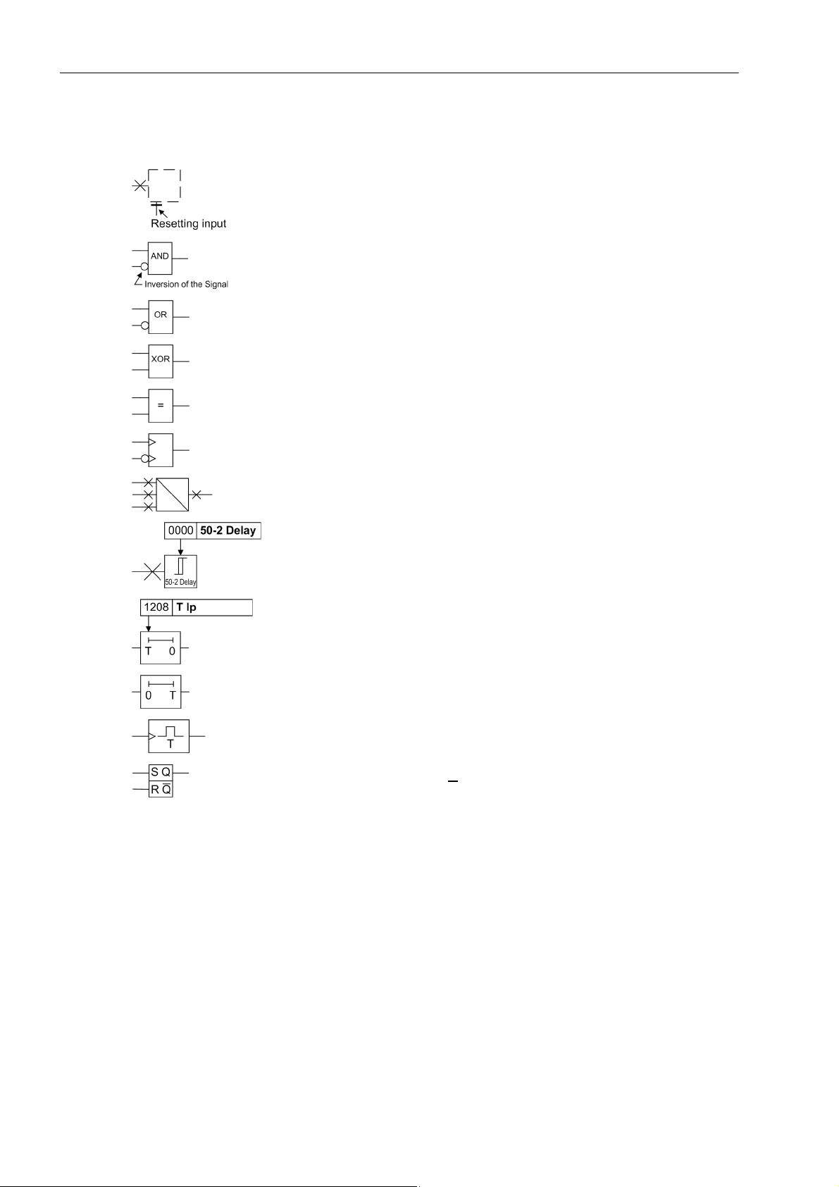
Besides these, graphical symbols are used in accordance with IEC 60617-12 and IEC 60617-13 or similar.
Some of the most frequently used are listed below:
Input signal of analog quantity
AND-gate operation of input values
OR-gate operation of input values
Exklusive OR-gate (antivalence): output is active, if only one of the
inputs is active
Coincidence gate (equivalence): output is active, if both inputs are
active or inactive at the same time
Dynamic inputs (edge-triggered) above with positive, below with negative edge
Formation of one analog output signal from a number of analog input
signals
Limit stage with setting address and parameter designator (name)
Timer (pickup delay T, example adjustable) with setting address and
parameter designator (name)
Timer (dropout delay T, example non-adjustable)
Dynamic triggered pulse timer T (monoflop)
Static memory (RS-flipflop) with setting input (S), resetting input (R),
output (Q) and inverted output (Q
)
■
8
E50417-G1140-C344-A4, Release date 08.2010
SIPROTEC, 7SK80, Manual

Contents
1 Introduction. . . . . . . . . . . . . . . . . . . . . . . . . . . . . . . . . . . . . . . . . . . . . . . . . . . . . . . . . . . . . . . . . . . . . . . . . . . . . .17
1.1 Overall Operation. . . . . . . . . . . . . . . . . . . . . . . . . . . . . . . . . . . . . . . . . . . . . . . . . . . . . . . . . . . . . . . . . .18
1.2 Application Scope . . . . . . . . . . . . . . . . . . . . . . . . . . . . . . . . . . . . . . . . . . . . . . . . . . . . . . . . . . . . . . . . .21
1.3 Characteristics. . . . . . . . . . . . . . . . . . . . . . . . . . . . . . . . . . . . . . . . . . . . . . . . . . . . . . . . . . . . . . . . . . . .23
2 Functions. . . . . . . . . . . . . . . . . . . . . . . . . . . . . . . . . . . . . . . . . . . . . . . . . . . . . . . . . . . . . . . . . . . . . . . . . . . . . . . .27
2.1 General . . . . . . . . . . . . . . . . . . . . . . . . . . . . . . . . . . . . . . . . . . . . . . . . . . . . . . . . . . . . . . . . . . . . . . . . .28
2.1.1 Functional Scope . . . . . . . . . . . . . . . . . . . . . . . . . . . . . . . . . . . . . . . . . . . . . . . . . . . . . . . . . . . . . . .28
2.1.1.1 Description . . . . . . . . . . . . . . . . . . . . . . . . . . . . . . . . . . . . . . . . . . . . . . . . . . . . . . . . . . . . . . . . .28
2.1.1.2 Setting Notes . . . . . . . . . . . . . . . . . . . . . . . . . . . . . . . . . . . . . . . . . . . . . . . . . . . . . . . . . . . . . . .28
2.1.1.3 Settings . . . . . . . . . . . . . . . . . . . . . . . . . . . . . . . . . . . . . . . . . . . . . . . . . . . . . . . . . . . . . . . . . . .30
2.1.2 Device, General Settings . . . . . . . . . . . . . . . . . . . . . . . . . . . . . . . . . . . . . . . . . . . . . . . . . . . . . . . . .32
2.1.2.1 Description . . . . . . . . . . . . . . . . . . . . . . . . . . . . . . . . . . . . . . . . . . . . . . . . . . . . . . . . . . . . . . . . .32
2.1.2.2 Setting Notes . . . . . . . . . . . . . . . . . . . . . . . . . . . . . . . . . . . . . . . . . . . . . . . . . . . . . . . . . . . . . . .33
2.1.2.3 Settings . . . . . . . . . . . . . . . . . . . . . . . . . . . . . . . . . . . . . . . . . . . . . . . . . . . . . . . . . . . . . . . . . . .33
2.1.2.4 Information List. . . . . . . . . . . . . . . . . . . . . . . . . . . . . . . . . . . . . . . . . . . . . . . . . . . . . . . . . . . . . .34
2.1.3 Power System Data 1 . . . . . . . . . . . . . . . . . . . . . . . . . . . . . . . . . . . . . . . . . . . . . . . . . . . . . . . . . . .35
2.1.3.1 Description . . . . . . . . . . . . . . . . . . . . . . . . . . . . . . . . . . . . . . . . . . . . . . . . . . . . . . . . . . . . . . . . .35
2.1.3.2 Setting Notes . . . . . . . . . . . . . . . . . . . . . . . . . . . . . . . . . . . . . . . . . . . . . . . . . . . . . . . . . . . . . . .35
2.1.3.3 Settings . . . . . . . . . . . . . . . . . . . . . . . . . . . . . . . . . . . . . . . . . . . . . . . . . . . . . . . . . . . . . . . . . . .46
2.1.3.4 Information List. . . . . . . . . . . . . . . . . . . . . . . . . . . . . . . . . . . . . . . . . . . . . . . . . . . . . . . . . . . . . .48
2.1.4 Oscillographic Fault Records . . . . . . . . . . . . . . . . . . . . . . . . . . . . . . . . . . . . . . . . . . . . . . . . . . . . . .49
2.1.4.1 Description . . . . . . . . . . . . . . . . . . . . . . . . . . . . . . . . . . . . . . . . . . . . . . . . . . . . . . . . . . . . . . . . .49
2.1.4.2 Setting Notes . . . . . . . . . . . . . . . . . . . . . . . . . . . . . . . . . . . . . . . . . . . . . . . . . . . . . . . . . . . . . . .50
2.1.4.3 Settings . . . . . . . . . . . . . . . . . . . . . . . . . . . . . . . . . . . . . . . . . . . . . . . . . . . . . . . . . . . . . . . . . . .50
2.1.4.4 Information List. . . . . . . . . . . . . . . . . . . . . . . . . . . . . . . . . . . . . . . . . . . . . . . . . . . . . . . . . . . . . .50
2.1.5 Settings Groups . . . . . . . . . . . . . . . . . . . . . . . . . . . . . . . . . . . . . . . . . . . . . . . . . . . . . . . . . . . . . . . .51
2.1.5.1 Description . . . . . . . . . . . . . . . . . . . . . . . . . . . . . . . . . . . . . . . . . . . . . . . . . . . . . . . . . . . . . . . . .51
2.1.5.2 Setting Notes . . . . . . . . . . . . . . . . . . . . . . . . . . . . . . . . . . . . . . . . . . . . . . . . . . . . . . . . . . . . . . .51
2.1.5.3 Settings . . . . . . . . . . . . . . . . . . . . . . . . . . . . . . . . . . . . . . . . . . . . . . . . . . . . . . . . . . . . . . . . . . .51
2.1.5.4 Information List. . . . . . . . . . . . . . . . . . . . . . . . . . . . . . . . . . . . . . . . . . . . . . . . . . . . . . . . . . . . . .52
2.1.6 Power System Data 2 . . . . . . . . . . . . . . . . . . . . . . . . . . . . . . . . . . . . . . . . . . . . . . . . . . . . . . . . . . .52
2.1.6.1 Description . . . . . . . . . . . . . . . . . . . . . . . . . . . . . . . . . . . . . . . . . . . . . . . . . . . . . . . . . . . . . . . . .52
2.1.6.2 Setting Notes . . . . . . . . . . . . . . . . . . . . . . . . . . . . . . . . . . . . . . . . . . . . . . . . . . . . . . . . . . . . . . .52
2.1.6.3 Settings . . . . . . . . . . . . . . . . . . . . . . . . . . . . . . . . . . . . . . . . . . . . . . . . . . . . . . . . . . . . . . . . . . .53
2.1.6.4 Information List. . . . . . . . . . . . . . . . . . . . . . . . . . . . . . . . . . . . . . . . . . . . . . . . . . . . . . . . . . . . . .53
2.1.7 EN100-Module . . . . . . . . . . . . . . . . . . . . . . . . . . . . . . . . . . . . . . . . . . . . . . . . . . . . . . . . . . . . . . . . .54
2.1.7.1 Functional Description . . . . . . . . . . . . . . . . . . . . . . . . . . . . . . . . . . . . . . . . . . . . . . . . . . . . . . . .54
2.1.7.2 Information List. . . . . . . . . . . . . . . . . . . . . . . . . . . . . . . . . . . . . . . . . . . . . . . . . . . . . . . . . . . . . .54
SIPROTEC, 7SK80, Manual
E50417-G1140-C344-A4, Release date 08.2010
9

Contents
2.2 Overcurrent Protection 50, 51, 50N, 51N . . . . . . . . . . . . . . . . . . . . . . . . . . . . . . . . . . . . . . . . . . . . . . . 55
2.2.1 General . . . . . . . . . . . . . . . . . . . . . . . . . . . . . . . . . . . . . . . . . . . . . . . . . . . . . . . . . . . . . . . . . . . . . . 55
2.2.2 Definite Time High-set Elements 50-3, 50-2, 50N-3, 50N-2 . . . . . . . . . . . . . . . . . . . . . . . . . . . . . . 56
2.2.3 Definite Time Overcurrent Elements 50-1, 50N-1 . . . . . . . . . . . . . . . . . . . . . . . . . . . . . . . . . . . . . . 59
2.2.4 Inverse Time Overcurrent Elements 51, 51N . . . . . . . . . . . . . . . . . . . . . . . . . . . . . . . . . . . . . . . .62
2.2.5 Dynamic Cold Load Pickup Function . . . . . . . . . . . . . . . . . . . . . . . . . . . . . . . . . . . . . . . . . . . . . . . 65
2.2.6 Inrush Restraint . . . . . . . . . . . . . . . . . . . . . . . . . . . . . . . . . . . . . . . . . . . . . . . . . . . . . . . . . . . 65
2.2.7 Pickup Logic and Tripping Logic . . . . . . . . . . . . . . . . . . . . . . . . . . . . . . . . . . . . . . . . . . . . . . . . . . . 68
2.2.8 Two-phase Overcurrent Protection (Only Non-directional) . . . . . . . . . . . . . . . . . . . . . . . . . . . . . 69
2.2.9 Fast Busbar Protection Using Reverse Interlocking . . . . . . . . . . . . . . . . . . . . . . . . . . . . . . . . . . 69
2.2.10 Setting Notes. . . . . . . . . . . . . . . . . . . . . . . . . . . . . . . . . . . . . . . . . . . . . . . . . . . . . . . . . . . . . . . . . . 70
2.2.11 Settings . . . . . . . . . . . . . . . . . . . . . . . . . . . . . . . . . . . . . . . . . . . . . . . . . . . . . . . . . . . . . . . . . . . . . . 75
2.2.12 Information List . . . . . . . . . . . . . . . . . . . . . . . . . . . . . . . . . . . . . . . . . . . . . . . . . . . . . . . . . . . . . . . . 78
2.3 Directional Ground Overcurrent Protection 67N . . . . . . . . . . . . . . . . . . . . . . . . . . . . . . . . . . . . . . . . . . 80
2.3.1 General . . . . . . . . . . . . . . . . . . . . . . . . . . . . . . . . . . . . . . . . . . . . . . . . . . . . . . . . . . . . . . . . . . . . . . 80
2.3.2 Definite Time, Directional High-set Current Element 67N-2 . . . . . . . . . . . . . . . . . . . . . . . . . . . . . . 81
2.3.3 Definite Time, Directional Overcurrent Element 67N-1 . . . . . . . . . . . . . . . . . . . . . . . . . . . . . . . . . . 82
2.3.4 Inverse Time, Directional Overcurrent Element 67N-TOC . . . . . . . . . . . . . . . . . . . . . . . . . . . . . . . 84
2.3.5 Interaction with Fuse Failure Monitor (FFM) . . . . . . . . . . . . . . . . . . . . . . . . . . . . . . . . . . . . . . . . . . 86
2.3.6 Dynamic Cold Load Pickup . . . . . . . . . . . . . . . . . . . . . . . . . . . . . . . . . . . . . . . . . . . . . . . . . . . . . . . 86
2.3.7 Inrush Restraint . . . . . . . . . . . . . . . . . . . . . . . . . . . . . . . . . . . . . . . . . . . . . . . . . . . . . . . . . . . . . . . . 86
2.3.8 Determination of Direction. . . . . . . . . . . . . . . . . . . . . . . . . . . . . . . . . . . . . . . . . . . . . . . . . . . . . . . . 87
2.3.9 Setting Notes. . . . . . . . . . . . . . . . . . . . . . . . . . . . . . . . . . . . . . . . . . . . . . . . . . . . . . . . . . . . . . . . . . 89
2.3.10 Settings . . . . . . . . . . . . . . . . . . . . . . . . . . . . . . . . . . . . . . . . . . . . . . . . . . . . . . . . . . . . . . . . . . . . . . 93
2.3.11 Information List . . . . . . . . . . . . . . . . . . . . . . . . . . . . . . . . . . . . . . . . . . . . . . . . . . . . . . . . . . . . . . . . 94
2.4 Dynamic Cold Load Pickup. . . . . . . . . . . . . . . . . . . . . . . . . . . . . . . . . . . . . . . . . . . . . . . . . . . . . . . . . . 95
2.4.1 Description . . . . . . . . . . . . . . . . . . . . . . . . . . . . . . . . . . . . . . . . . . . . . . . . . . . . . . . . . . . . . . . . . . . 95
2.4.2 Setting Notes. . . . . . . . . . . . . . . . . . . . . . . . . . . . . . . . . . . . . . . . . . . . . . . . . . . . . . . . . . . . . . . . . . 98
2.4.3 Settings . . . . . . . . . . . . . . . . . . . . . . . . . . . . . . . . . . . . . . . . . . . . . . . . . . . . . . . . . . . . . . . . . . . . . . 99
2.4.4 Information List . . . . . . . . . . . . . . . . . . . . . . . . . . . . . . . . . . . . . . . . . . . . . . . . . . . . . . . . . . . . . . . 100
2.5 Voltage Protection 27, 59 . . . . . . . . . . . . . . . . . . . . . . . . . . . . . . . . . . . . . . . . . . . . . . . . . . . . . . . . . . 101
2.5.1 Measurement Principle . . . . . . . . . . . . . . . . . . . . . . . . . . . . . . . . . . . . . . . . . . . . . . . . . . . . . . . . . 101
2.5.2 Overvoltage Protection 59. . . . . . . . . . . . . . . . . . . . . . . . . . . . . . . . . . . . . . . . . . . . . . . . . . . . . . . 103
2.5.3 Undervoltage Protection 27. . . . . . . . . . . . . . . . . . . . . . . . . . . . . . . . . . . . . . . . . . . . . . . . . . . . . . 104
2.5.4 Setting Notes. . . . . . . . . . . . . . . . . . . . . . . . . . . . . . . . . . . . . . . . . . . . . . . . . . . . . . . . . . . . . . . . . 107
2.5.5 Settings . . . . . . . . . . . . . . . . . . . . . . . . . . . . . . . . . . . . . . . . . . . . . . . . . . . . . . . . . . . . . . . . . . . . . 110
2.5.6 Information List . . . . . . . . . . . . . . . . . . . . . . . . . . . . . . . . . . . . . . . . . . . . . . . . . . . . . . . . . . . . . . . 111
2.6 Negative Sequence Protection 46. . . . . . . . . . . . . . . . . . . . . . . . . . . . . . . . . . . . . . . . . . . . . . . . . . . . 112
2.6.1 Definite Time Characteristic . . . . . . . . . . . . . . . . . . . . . . . . . . . . . . . . . . . . . . . . . . . . . . . . . . . . . 112
2.6.2 Inverse Time Characteristic 46-TOC. . . . . . . . . . . . . . . . . . . . . . . . . . . . . . . . . . . . . . . . . . . . . . . 113
2.6.3 Setting Notes. . . . . . . . . . . . . . . . . . . . . . . . . . . . . . . . . . . . . . . . . . . . . . . . . . . . . . . . . . . . . . . . . 116
2.6.4 Settings . . . . . . . . . . . . . . . . . . . . . . . . . . . . . . . . . . . . . . . . . . . . . . . . . . . . . . . . . . . . . . . . . . . . . 119
2.6.5 Information List . . . . . . . . . . . . . . . . . . . . . . . . . . . . . . . . . . . . . . . . . . . . . . . . . . . . . . . . . . . . . . . 119
10
E50417-G1140-C344-A4, Release date 08.2010
SIPROTEC, 7SK80, Manual

Contents
2.7 Motor Protection (Motor Starting Protection 48, Motor Restart Inhibit 66, Load Jam Protection) . . . .120
2.7.1 Motor Starting Protection 48. . . . . . . . . . . . . . . . . . . . . . . . . . . . . . . . . . . . . . . . . . . . . . . . . . . . . .120
2.7.1.1 Description . . . . . . . . . . . . . . . . . . . . . . . . . . . . . . . . . . . . . . . . . . . . . . . . . . . . . . . . . . . . . . . .120
2.7.1.2 Setting Notes . . . . . . . . . . . . . . . . . . . . . . . . . . . . . . . . . . . . . . . . . . . . . . . . . . . . . . . . . . . . . .123
2.7.2 Motor Restart Inhibit 66 . . . . . . . . . . . . . . . . . . . . . . . . . . . . . . . . . . . . . . . . . . . . . . . . . . . . . . . . .126
2.7.2.1 Description . . . . . . . . . . . . . . . . . . . . . . . . . . . . . . . . . . . . . . . . . . . . . . . . . . . . . . . . . . . . . . . .126
2.7.2.2 Setting Notes . . . . . . . . . . . . . . . . . . . . . . . . . . . . . . . . . . . . . . . . . . . . . . . . . . . . . . . . . . . . . .132
2.7.3 Load Jam Protection . . . . . . . . . . . . . . . . . . . . . . . . . . . . . . . . . . . . . . . . . . . . . . . . . . . . . . . . . . .136
2.7.3.1 Mode of Operation . . . . . . . . . . . . . . . . . . . . . . . . . . . . . . . . . . . . . . . . . . . . . . . . . . . . . . . . . .136
2.7.3.2 Setting Notes . . . . . . . . . . . . . . . . . . . . . . . . . . . . . . . . . . . . . . . . . . . . . . . . . . . . . . . . . . . . . .138
2.7.4 Motor (Motor Starting Protection 48, Motor Restart Inhibit 66, Load Jam Protection) . . . . . . . . . .140
2.7.4.1 Settings . . . . . . . . . . . . . . . . . . . . . . . . . . . . . . . . . . . . . . . . . . . . . . . . . . . . . . . . . . . . . . . . . .140
2.7.4.2 Information List. . . . . . . . . . . . . . . . . . . . . . . . . . . . . . . . . . . . . . . . . . . . . . . . . . . . . . . . . . . . .142
2.8 Frequency Protection 81 O/U . . . . . . . . . . . . . . . . . . . . . . . . . . . . . . . . . . . . . . . . . . . . . . . . . . . . . . .143
2.8.1 Description . . . . . . . . . . . . . . . . . . . . . . . . . . . . . . . . . . . . . . . . . . . . . . . . . . . . . . . . . . . . . . . . . . .143
2.8.2 Setting Notes . . . . . . . . . . . . . . . . . . . . . . . . . . . . . . . . . . . . . . . . . . . . . . . . . . . . . . . . . . . . . . . . .144
2.8.3 Settings . . . . . . . . . . . . . . . . . . . . . . . . . . . . . . . . . . . . . . . . . . . . . . . . . . . . . . . . . . . . . . . . . . . . .145
2.8.4 Information List. . . . . . . . . . . . . . . . . . . . . . . . . . . . . . . . . . . . . . . . . . . . . . . . . . . . . . . . . . . . . . . .146
2.9 Thermal Overload Protection 49 . . . . . . . . . . . . . . . . . . . . . . . . . . . . . . . . . . . . . . . . . . . . . . . . . . . . .147
2.9.1 Description . . . . . . . . . . . . . . . . . . . . . . . . . . . . . . . . . . . . . . . . . . . . . . . . . . . . . . . . . . . . . . . . . . .147
2.9.2 Setting Notes . . . . . . . . . . . . . . . . . . . . . . . . . . . . . . . . . . . . . . . . . . . . . . . . . . . . . . . . . . . . . . . . .151
2.9.3 Settings . . . . . . . . . . . . . . . . . . . . . . . . . . . . . . . . . . . . . . . . . . . . . . . . . . . . . . . . . . . . . . . . . . . . .156
2.9.4 Information List. . . . . . . . . . . . . . . . . . . . . . . . . . . . . . . . . . . . . . . . . . . . . . . . . . . . . . . . . . . . . . . .156
2.10 Monitoring Functions . . . . . . . . . . . . . . . . . . . . . . . . . . . . . . . . . . . . . . . . . . . . . . . . . . . . . . . . . . . . . .157
2.10.1 Measurement Supervision . . . . . . . . . . . . . . . . . . . . . . . . . . . . . . . . . . . . . . . . . . . . . . . . . . . . . . .157
2.10.1.1 General. . . . . . . . . . . . . . . . . . . . . . . . . . . . . . . . . . . . . . . . . . . . . . . . . . . . . . . . . . . . . . . . . . .157
2.10.1.2 Hardware Monitoring . . . . . . . . . . . . . . . . . . . . . . . . . . . . . . . . . . . . . . . . . . . . . . . . . . . . . . .157
2.10.1.3 Software Monitoring . . . . . . . . . . . . . . . . . . . . . . . . . . . . . . . . . . . . . . . . . . . . . . . . . . . . . . . .160
2.10.1.4 Monitoring of the Transformer Circuits . . . . . . . . . . . . . . . . . . . . . . . . . . . . . . . . . . . . . . . . . . .160
2.10.1.5 Measuring Voltage Failure Detection . . . . . . . . . . . . . . . . . . . . . . . . . . . . . . . . . . . . . . . . . .162
2.10.1.6 Broken Wire Monitoring of Voltage Transformer Circuits . . . . . . . . . . . . . . . . . . . . . . . . . . . . .167
2.10.1.7 Setting Notes . . . . . . . . . . . . . . . . . . . . . . . . . . . . . . . . . . . . . . . . . . . . . . . . . . . . . . . . . . . . . .168
2.10.1.8 Settings . . . . . . . . . . . . . . . . . . . . . . . . . . . . . . . . . . . . . . . . . . . . . . . . . . . . . . . . . . . . . . . . . .170
2.10.1.9 Information List. . . . . . . . . . . . . . . . . . . . . . . . . . . . . . . . . . . . . . . . . . . . . . . . . . . . . . . . . . . . .171
2.10.2 Trip Circuit Supervision 74TC . . . . . . . . . . . . . . . . . . . . . . . . . . . . . . . . . . . . . . . . . . . . . . . . . . . .171
2.10.2.1 Description . . . . . . . . . . . . . . . . . . . . . . . . . . . . . . . . . . . . . . . . . . . . . . . . . . . . . . . . . . . . . . . .172
2.10.2.2 Setting Notes . . . . . . . . . . . . . . . . . . . . . . . . . . . . . . . . . . . . . . . . . . . . . . . . . . . . . . . . . . . . . .174
2.10.2.3 Settings . . . . . . . . . . . . . . . . . . . . . . . . . . . . . . . . . . . . . . . . . . . . . . . . . . . . . . . . . . . . . . . . . .175
2.10.2.4 Information List. . . . . . . . . . . . . . . . . . . . . . . . . . . . . . . . . . . . . . . . . . . . . . . . . . . . . . . . . . . . .175
2.10.3 Malfunction Responses of the Monitoring Functions . . . . . . . . . . . . . . . . . . . . . . . . . . . . . . . . . . .175
2.10.3.1 Description . . . . . . . . . . . . . . . . . . . . . . . . . . . . . . . . . . . . . . . . . . . . . . . . . . . . . . . . . . . . . . . .175
2.11 Ground Fault Protection 64, 67N(s), 50N(s), 51N(s) . . . . . . . . . . . . . . . . . . . . . . . . . . . . . . . . . . . . . .178
2.11.1 Ground Fault Detection for cos-ϕ– / sin-ϕ Measurement (Standard Method) . . . . . . . . . . . . . . . .178
2.11.2 Ground Fault Detection for V0/I0-ϕ
Measurement. . . . . . . . . . . . . . . . . . . . . . . . . . . . . . . . . . . . .185
2.11.3 Ground Fault Location . . . . . . . . . . . . . . . . . . . . . . . . . . . . . . . . . . . . . . . . . . . . . . . . . . . . . . . . . .190
2.11.4 Setting Notes . . . . . . . . . . . . . . . . . . . . . . . . . . . . . . . . . . . . . . . . . . . . . . . . . . . . . . . . . . . . . . . . .191
2.11.5 Settings . . . . . . . . . . . . . . . . . . . . . . . . . . . . . . . . . . . . . . . . . . . . . . . . . . . . . . . . . . . . . . . . . . . . .197
2.11.6 Information List. . . . . . . . . . . . . . . . . . . . . . . . . . . . . . . . . . . . . . . . . . . . . . . . . . . . . . . . . . . . . . . .199
SIPROTEC, 7SK80, Manual
E50417-G1140-C344-A4, Release date 08.2010
11

Contents
2.12 Breaker Failure Protection 50BF. . . . . . . . . . . . . . . . . . . . . . . . . . . . . . . . . . . . . . . . . . . . . . . . . . . . . 200
2.12.1 Description . . . . . . . . . . . . . . . . . . . . . . . . . . . . . . . . . . . . . . . . . . . . . . . . . . . . . . . . . . . . . . . . . . 200
2.12.2 Setting Notes. . . . . . . . . . . . . . . . . . . . . . . . . . . . . . . . . . . . . . . . . . . . . . . . . . . . . . . . . . . . . . . . . 204
2.12.3 Settings . . . . . . . . . . . . . . . . . . . . . . . . . . . . . . . . . . . . . . . . . . . . . . . . . . . . . . . . . . . . . . . . . . . . . 205
2.12.4 Information List . . . . . . . . . . . . . . . . . . . . . . . . . . . . . . . . . . . . . . . . . . . . . . . . . . . . . . . . . . . . . . . 205
2.13 Flexible Protection Functions . . . . . . . . . . . . . . . . . . . . . . . . . . . . . . . . . . . . . . . . . . . . . . . . . . . . . . . 206
2.13.1 Description . . . . . . . . . . . . . . . . . . . . . . . . . . . . . . . . . . . . . . . . . . . . . . . . . . . . . . . . . . . . . . . . . . 206
2.13.2 Setting Notes. . . . . . . . . . . . . . . . . . . . . . . . . . . . . . . . . . . . . . . . . . . . . . . . . . . . . . . . . . . . . . . . . 211
2.13.3 Settings . . . . . . . . . . . . . . . . . . . . . . . . . . . . . . . . . . . . . . . . . . . . . . . . . . . . . . . . . . . . . . . . . . . . . 216
2.13.4 Information List . . . . . . . . . . . . . . . . . . . . . . . . . . . . . . . . . . . . . . . . . . . . . . . . . . . . . . . . . . . . . . . 218
2.14 Reverse-Power Protection Application with Flexible Protection Function. . . . . . . . . . . . . . . . . . . . . . 219
2.14.1 Description . . . . . . . . . . . . . . . . . . . . . . . . . . . . . . . . . . . . . . . . . . . . . . . . . . . . . . . . . . . . . . . . . . 219
2.14.2 Implementation of the Reverse Power Protection . . . . . . . . . . . . . . . . . . . . . . . . . . . . . . . . . . . . . 222
2.14.3 Configuring the Reverse Power Protection in DIGSI. . . . . . . . . . . . . . . . . . . . . . . . . . . . . . . . . . . 224
2.15 Temperature Detection via RTD Boxes. . . . . . . . . . . . . . . . . . . . . . . . . . . . . . . . . . . . . . . . . . . . . . . . 227
2.15.1 Description . . . . . . . . . . . . . . . . . . . . . . . . . . . . . . . . . . . . . . . . . . . . . . . . . . . . . . . . . . . . . . . . . . 227
2.15.2 Setting Notes. . . . . . . . . . . . . . . . . . . . . . . . . . . . . . . . . . . . . . . . . . . . . . . . . . . . . . . . . . . . . . . . . 229
2.15.3 Settings . . . . . . . . . . . . . . . . . . . . . . . . . . . . . . . . . . . . . . . . . . . . . . . . . . . . . . . . . . . . . . . . . . . . . 232
2.15.4 Information List . . . . . . . . . . . . . . . . . . . . . . . . . . . . . . . . . . . . . . . . . . . . . . . . . . . . . . . . . . . . . . . 237
2.16 Phase Rotation . . . . . . . . . . . . . . . . . . . . . . . . . . . . . . . . . . . . . . . . . . . . . . . . . . . . . . . . . . . . . . . . . . 238
2.16.1 Description . . . . . . . . . . . . . . . . . . . . . . . . . . . . . . . . . . . . . . . . . . . . . . . . . . . . . . . . . . . . . . . . . . 238
2.16.2 Setting Notes. . . . . . . . . . . . . . . . . . . . . . . . . . . . . . . . . . . . . . . . . . . . . . . . . . . . . . . . . . . . . . . . . 239
2.17 Function Logic. . . . . . . . . . . . . . . . . . . . . . . . . . . . . . . . . . . . . . . . . . . . . . . . . . . . . . . . . . . . . . . . . . . 240
2.17.1 Pickup Logic of the Entire Device . . . . . . . . . . . . . . . . . . . . . . . . . . . . . . . . . . . . . . . . . . . . . . . . . 240
2.17.2 Tripping Logic of the Entire Device . . . . . . . . . . . . . . . . . . . . . . . . . . . . . . . . . . . . . . . . . . . . . . . . 241
2.17.3 Setting Notes. . . . . . . . . . . . . . . . . . . . . . . . . . . . . . . . . . . . . . . . . . . . . . . . . . . . . . . . . . . . . . . . . 241
12
E50417-G1140-C344-A4, Release date 08.2010
SIPROTEC, 7SK80, Manual

Contents
2.18 Auxiliary Functions. . . . . . . . . . . . . . . . . . . . . . . . . . . . . . . . . . . . . . . . . . . . . . . . . . . . . . . . . . . . . . . .242
2.18.1 Message Processing . . . . . . . . . . . . . . . . . . . . . . . . . . . . . . . . . . . . . . . . . . . . . . . . . . . . . . . . . . .242
2.18.1.1 LEDs and Binary Outputs (Output Relays). . . . . . . . . . . . . . . . . . . . . . . . . . . . . . . . . . . . . . . .242
2.18.1.2 Information via Display Field or PC . . . . . . . . . . . . . . . . . . . . . . . . . . . . . . . . . . . . . . . . . . . . .243
2.18.1.3 Information to a Control Center . . . . . . . . . . . . . . . . . . . . . . . . . . . . . . . . . . . . . . . . . . . . . . . .244
2.18.2 Statistics. . . . . . . . . . . . . . . . . . . . . . . . . . . . . . . . . . . . . . . . . . . . . . . . . . . . . . . . . . . . . . . . . . . . .245
2.18.2.1 Description . . . . . . . . . . . . . . . . . . . . . . . . . . . . . . . . . . . . . . . . . . . . . . . . . . . . . . . . . . . . . . . .245
2.18.2.2 Circuit Breaker Maintenance . . . . . . . . . . . . . . . . . . . . . . . . . . . . . . . . . . . . . . . . . . . . . . . . . .246
2.18.2.3 Motor Statistics . . . . . . . . . . . . . . . . . . . . . . . . . . . . . . . . . . . . . . . . . . . . . . . . . . . . . . . . . . . . .252
2.18.2.4 Setting Notes . . . . . . . . . . . . . . . . . . . . . . . . . . . . . . . . . . . . . . . . . . . . . . . . . . . . . . . . . . . . . .252
2.18.2.5 Information List. . . . . . . . . . . . . . . . . . . . . . . . . . . . . . . . . . . . . . . . . . . . . . . . . . . . . . . . . . . . .255
2.18.3 Measurement . . . . . . . . . . . . . . . . . . . . . . . . . . . . . . . . . . . . . . . . . . . . . . . . . . . . . . . . . . . . . . . . .256
2.18.3.1 Display of Measured Values . . . . . . . . . . . . . . . . . . . . . . . . . . . . . . . . . . . . . . . . . . . . . . . . . . .257
2.18.3.2 Transmitting Measured Values . . . . . . . . . . . . . . . . . . . . . . . . . . . . . . . . . . . . . . . . . . . . . . . . .259
2.18.3.3 Information List. . . . . . . . . . . . . . . . . . . . . . . . . . . . . . . . . . . . . . . . . . . . . . . . . . . . . . . . . . . . .259
2.18.4 Average Measurements. . . . . . . . . . . . . . . . . . . . . . . . . . . . . . . . . . . . . . . . . . . . . . . . . . . . . . . . .261
2.18.4.1 Description . . . . . . . . . . . . . . . . . . . . . . . . . . . . . . . . . . . . . . . . . . . . . . . . . . . . . . . . . . . . . . . .261
2.18.4.2 Setting Notes . . . . . . . . . . . . . . . . . . . . . . . . . . . . . . . . . . . . . . . . . . . . . . . . . . . . . . . . . . . . . .261
2.18.4.3 Settings . . . . . . . . . . . . . . . . . . . . . . . . . . . . . . . . . . . . . . . . . . . . . . . . . . . . . . . . . . . . . . . . . .261
2.18.4.4 Information List. . . . . . . . . . . . . . . . . . . . . . . . . . . . . . . . . . . . . . . . . . . . . . . . . . . . . . . . . . . . .262
2.18.5 Min/Max Measurement Setup . . . . . . . . . . . . . . . . . . . . . . . . . . . . . . . . . . . . . . . . . . . . . . . . . . . .262
2.18.5.1 Description . . . . . . . . . . . . . . . . . . . . . . . . . . . . . . . . . . . . . . . . . . . . . . . . . . . . . . . . . . . . . . . .262
2.18.5.2 Setting Notes . . . . . . . . . . . . . . . . . . . . . . . . . . . . . . . . . . . . . . . . . . . . . . . . . . . . . . . . . . . . . .262
2.18.5.3 Settings . . . . . . . . . . . . . . . . . . . . . . . . . . . . . . . . . . . . . . . . . . . . . . . . . . . . . . . . . . . . . . . . . .263
2.18.5.4 Information List. . . . . . . . . . . . . . . . . . . . . . . . . . . . . . . . . . . . . . . . . . . . . . . . . . . . . . . . . . . . .263
2.18.6 Set Points for Measured Values. . . . . . . . . . . . . . . . . . . . . . . . . . . . . . . . . . . . . . . . . . . . . . . . . . .265
2.18.6.1 Setting Notes . . . . . . . . . . . . . . . . . . . . . . . . . . . . . . . . . . . . . . . . . . . . . . . . . . . . . . . . . . . . . .265
2.18.7 Set Points for Statistic . . . . . . . . . . . . . . . . . . . . . . . . . . . . . . . . . . . . . . . . . . . . . . . . . . . . . . . . . .266
2.18.7.1 Description . . . . . . . . . . . . . . . . . . . . . . . . . . . . . . . . . . . . . . . . . . . . . . . . . . . . . . . . . . . . . . . .266
2.18.7.2 Setting Notes . . . . . . . . . . . . . . . . . . . . . . . . . . . . . . . . . . . . . . . . . . . . . . . . . . . . . . . . . . . . . .266
2.18.7.3 Information List. . . . . . . . . . . . . . . . . . . . . . . . . . . . . . . . . . . . . . . . . . . . . . . . . . . . . . . . . . . . .266
2.18.8 Energy Metering. . . . . . . . . . . . . . . . . . . . . . . . . . . . . . . . . . . . . . . . . . . . . . . . . . . . . . . . . . . . . . .267
2.18.8.1 Description . . . . . . . . . . . . . . . . . . . . . . . . . . . . . . . . . . . . . . . . . . . . . . . . . . . . . . . . . . . . . . . .267
2.18.8.2 Setting Notes . . . . . . . . . . . . . . . . . . . . . . . . . . . . . . . . . . . . . . . . . . . . . . . . . . . . . . . . . . . . . .267
2.18.8.3 Settings . . . . . . . . . . . . . . . . . . . . . . . . . . . . . . . . . . . . . . . . . . . . . . . . . . . . . . . . . . . . . . . . . .267
2.18.8.4 Information List. . . . . . . . . . . . . . . . . . . . . . . . . . . . . . . . . . . . . . . . . . . . . . . . . . . . . . . . . . . . .267
2.18.9 Commissioning Aids. . . . . . . . . . . . . . . . . . . . . . . . . . . . . . . . . . . . . . . . . . . . . . . . . . . . . . . . . . . .268
2.18.9.1 Description . . . . . . . . . . . . . . . . . . . . . . . . . . . . . . . . . . . . . . . . . . . . . . . . . . . . . . . . . . . . . . . .268
2.19 Breaker Control . . . . . . . . . . . . . . . . . . . . . . . . . . . . . . . . . . . . . . . . . . . . . . . . . . . . . . . . . . . . . . . . . .270
2.19.1 Control Device . . . . . . . . . . . . . . . . . . . . . . . . . . . . . . . . . . . . . . . . . . . . . . . . . . . . . . . . . . . . . . . .270
2.19.1.1 Description . . . . . . . . . . . . . . . . . . . . . . . . . . . . . . . . . . . . . . . . . . . . . . . . . . . . . . . . . . . . . . . .270
2.19.1.2 Information List. . . . . . . . . . . . . . . . . . . . . . . . . . . . . . . . . . . . . . . . . . . . . . . . . . . . . . . . . . . . .271
2.19.2 Command Types . . . . . . . . . . . . . . . . . . . . . . . . . . . . . . . . . . . . . . . . . . . . . . . . . . . . . . . . . . . . . .272
2.19.2.1 Description . . . . . . . . . . . . . . . . . . . . . . . . . . . . . . . . . . . . . . . . . . . . . . . . . . . . . . . . . . . . . . . .272
2.19.3 Command Sequence . . . . . . . . . . . . . . . . . . . . . . . . . . . . . . . . . . . . . . . . . . . . . . . . . . . . . . . . . . .273
2.19.3.1 Description . . . . . . . . . . . . . . . . . . . . . . . . . . . . . . . . . . . . . . . . . . . . . . . . . . . . . . . . . . . . . . . .273
2.19.4 Interlocking. . . . . . . . . . . . . . . . . . . . . . . . . . . . . . . . . . . . . . . . . . . . . . . . . . . . . . . . . . . . . . . . . . .274
2.19.4.1 Description . . . . . . . . . . . . . . . . . . . . . . . . . . . . . . . . . . . . . . . . . . . . . . . . . . . . . . . . . . . . . . . .274
2.19.5 Command Logging. . . . . . . . . . . . . . . . . . . . . . . . . . . . . . . . . . . . . . . . . . . . . . . . . . . . . . . . . . . . .281
2.19.5.1 Description . . . . . . . . . . . . . . . . . . . . . . . . . . . . . . . . . . . . . . . . . . . . . . . . . . . . . . . . . . . . . . . .281
SIPROTEC, 7SK80, Manual
E50417-G1140-C344-A4, Release date 08.2010
13

Contents
2.20 Notes on Device Operation . . . . . . . . . . . . . . . . . . . . . . . . . . . . . . . . . . . . . . . . . . . . . . . . . . . . . . . . . 282
2.20.1 Different operation. . . . . . . . . . . . . . . . . . . . . . . . . . . . . . . . . . . . . . . . . . . . . . . . . . . . . . . . . . . . . 282
3 Mounting and Commissioning . . . . . . . . . . . . . . . . . . . . . . . . . . . . . . . . . . . . . . . . . . . . . . . . . . . . . . . . . . . . . 285
3.1 Mounting and Connections . . . . . . . . . . . . . . . . . . . . . . . . . . . . . . . . . . . . . . . . . . . . . . . . . . . . . . . . . 286
3.1.1 Configuration Information . . . . . . . . . . . . . . . . . . . . . . . . . . . . . . . . . . . . . . . . . . . . . . . . . . . . . . . 286
3.1.2 Hardware Modifications. . . . . . . . . . . . . . . . . . . . . . . . . . . . . . . . . . . . . . . . . . . . . . . . . . . . . . . . . 290
3.1.2.1 Disassembly . . . . . . . . . . . . . . . . . . . . . . . . . . . . . . . . . . . . . . . . . . . . . . . . . . . . . . . . . . . . . . 290
3.1.2.2 Connections of the Current Terminals . . . . . . . . . . . . . . . . . . . . . . . . . . . . . . . . . . . . . . . . . . .293
3.1.2.3 Connections of the Voltage Terminals . . . . . . . . . . . . . . . . . . . . . . . . . . . . . . . . . . . . . . . . . .295
3.1.2.4 Connection of the temperature sensors to the I/O 2 extension module. . . . . . . . . . . . . . . . . . 295
3.1.2.5 Interface Modules . . . . . . . . . . . . . . . . . . . . . . . . . . . . . . . . . . . . . . . . . . . . . . . . . . . . . . . . . . 298
3.1.2.6 Reassembly . . . . . . . . . . . . . . . . . . . . . . . . . . . . . . . . . . . . . . . . . . . . . . . . . . . . . . . . . . . . . . . 300
3.1.3 Installation . . . . . . . . . . . . . . . . . . . . . . . . . . . . . . . . . . . . . . . . . . . . . . . . . . . . . . . . . . . . . . . . . . . 302
3.1.3.1 General . . . . . . . . . . . . . . . . . . . . . . . . . . . . . . . . . . . . . . . . . . . . . . . . . . . . . . . . . . . . . . . . . . 302
3.1.3.2 Panel Flush Mounting . . . . . . . . . . . . . . . . . . . . . . . . . . . . . . . . . . . . . . . . . . . . . . . . . . . . . . . 303
3.1.3.3 Cubicle Mounting . . . . . . . . . . . . . . . . . . . . . . . . . . . . . . . . . . . . . . . . . . . . . . . . . . . . . . . . . . . 304
3.1.3.4 Panel Surface Mounting . . . . . . . . . . . . . . . . . . . . . . . . . . . . . . . . . . . . . . . . . . . . . . . . . . . . . 305
3.2 Checking Connections . . . . . . . . . . . . . . . . . . . . . . . . . . . . . . . . . . . . . . . . . . . . . . . . . . . . . . . . . . . . 306
3.2.1 Checking the Data Connections of the Interfaces . . . . . . . . . . . . . . . . . . . . . . . . . . . . . . . . . . . . . 306
3.2.2 Checking the System Connections . . . . . . . . . . . . . . . . . . . . . . . . . . . . . . . . . . . . . . . . . . . . . . . . 310
3.3 Commissioning . . . . . . . . . . . . . . . . . . . . . . . . . . . . . . . . . . . . . . . . . . . . . . . . . . . . . . . . . . . . . . . . . . 312
3.3.1 Test Mode and Transmission Block. . . . . . . . . . . . . . . . . . . . . . . . . . . . . . . . . . . . . . . . . . . . . . . . 313
3.3.2 Testing the System Interface (at Port B) . . . . . . . . . . . . . . . . . . . . . . . . . . . . . . . . . . . . . . . . . . . . 313
3.3.3 Configuring Communication Modules . . . . . . . . . . . . . . . . . . . . . . . . . . . . . . . . . . . . . . . . . . . . . .315
3.3.4 Checking the Status of Binary Inputs and Outputs . . . . . . . . . . . . . . . . . . . . . . . . . . . . . . . . . . . . 318
3.3.5 Tests for Circuit Breaker Failure Protection. . . . . . . . . . . . . . . . . . . . . . . . . . . . . . . . . . . . . . . . . . 321
3.3.6 Testing User-Defined Functions . . . . . . . . . . . . . . . . . . . . . . . . . . . . . . . . . . . . . . . . . . . . . . . . . . 322
3.3.7 Current, Voltage, and Phase Rotation Testing. . . . . . . . . . . . . . . . . . . . . . . . . . . . . . . . . . . . . . . .323
3.3.8 Testing the Reverse Interlocking Scheme . . . . . . . . . . . . . . . . . . . . . . . . . . . . . . . . . . . . . . . . . . .324
3.3.9 Direction Check with Load Current . . . . . . . . . . . . . . . . . . . . . . . . . . . . . . . . . . . . . . . . . . . . . . . . 325
3.3.10 Polarity Check for Voltage Input V
. . . . . . . . . . . . . . . . . . . . . . . . . . . . . . . . . . . . . . . . . . . . . . . . 326
3
3.3.11 Ground Fault Check . . . . . . . . . . . . . . . . . . . . . . . . . . . . . . . . . . . . . . . . . . . . . . . . . . . . . . . . . . . 326
3.3.12 Polarity Check for Current Input I
. . . . . . . . . . . . . . . . . . . . . . . . . . . . . . . . . . . . . . . . . . . . . . . . 327
N
3.3.13 Checking the Temperature Detection . . . . . . . . . . . . . . . . . . . . . . . . . . . . . . . . . . . . . . . . . . . . . . 329
3.3.14 Trip/Close Tests for the Configured Operating Devices . . . . . . . . . . . . . . . . . . . . . . . . . . . . . . . . 330
3.3.15 Creating Oscillographic Recordings for Tests . . . . . . . . . . . . . . . . . . . . . . . . . . . . . . . . . . . . . . . . 331
3.4 Final Preparation of the Device. . . . . . . . . . . . . . . . . . . . . . . . . . . . . . . . . . . . . . . . . . . . . . . . . . . . . . 332
14
E50417-G1140-C344-A4, Release date 08.2010
SIPROTEC, 7SK80, Manual

Contents
4 Technical Data. . . . . . . . . . . . . . . . . . . . . . . . . . . . . . . . . . . . . . . . . . . . . . . . . . . . . . . . . . . . . . . . . . . . . . . . . . .333
4.1 General Device Data . . . . . . . . . . . . . . . . . . . . . . . . . . . . . . . . . . . . . . . . . . . . . . . . . . . . . . . . . . . . . .334
4.1.1 Analog Inputs . . . . . . . . . . . . . . . . . . . . . . . . . . . . . . . . . . . . . . . . . . . . . . . . . . . . . . . . . . . . .334
4.1.2 Auxiliary Voltage . . . . . . . . . . . . . . . . . . . . . . . . . . . . . . . . . . . . . . . . . . . . . . . . . . . . . . .335
4.1.3 Binary Inputs and Outputs . . . . . . . . . . . . . . . . . . . . . . . . . . . . . . . . . . . . . . . . . . . . . . .336
4.1.4 Communication Interfaces . . . . . . . . . . . . . . . . . . . . . . . . . . . . . . . . . . . . . . . . . . . . . . . . . . . . .337
4.1.5 Electrical Tests . . . . . . . . . . . . . . . . . . . . . . . . . . . . . . . . . . . . . . . . . . . . . . . . . . . . . . . . . . . .339
4.1.6 Mechanical Stress Tests . . . . . . . . . . . . . . . . . . . . . . . . . . . . . . . . . . . . . . . . . . . . . . . . . . . .342
4.1.7 Climatic Stress Tests . . . . . . . . . . . . . . . . . . . . . . . . . . . . . . . . . . . . . . . . . . . . . . . . . . . . . . .343
4.1.8 Service conditions . . . . . . . . . . . . . . . . . . . . . . . . . . . . . . . . . . . . . . . . . . . . . . . . . . . . . . . . .343
4.1.9 Design . . . . . . . . . . . . . . . . . . . . . . . . . . . . . . . . . . . . . . . . . . . . . . . . . . . . . . . . . . . . . . . . . .344
4.1.10 UL-certification conditions . . . . . . . . . . . . . . . . . . . . . . . . . . . . . . . . . . . . . . . . . . . . . . . . . . . . . . .344
4.2 Definite-Time Overcurrent Protection 50(N) . . . . . . . . . . . . . . . . . . . . . . . . . . . . . . . . . . . . . . . . .345
4.3 Inverse-Time Overcurrent Protection 51(N) . . . . . . . . . . . . . . . . . . . . . . . . . . . . . . . . . . . . . . . . .347
4.4 Directional Ground Overcurrent Protection 67N . . . . . . . . . . . . . . . . . . . . . . . . . . . . . . . . . . . . . . . . .358
4.5 Inrush Restraint . . . . . . . . . . . . . . . . . . . . . . . . . . . . . . . . . . . . . . . . . . . . . . . . . . . . . . . . . . . .359
4.6 Dynamic Cold Load Pickup . . . . . . . . . . . . . . . . . . . . . . . . . . . . . . . . . . . . . . . . . . . . . . . . . . . . . .360
4.7 Voltage Protection 27, 59 . . . . . . . . . . . . . . . . . . . . . . . . . . . . . . . . . . . . . . . . . . . . . . . . . . . . . .361
4.8 Negative Sequence Protection 46-1, 46-2 . . . . . . . . . . . . . . . . . . . . . . . . . . . . . . . . . . . . . . . . . .363
4.9 Negative Sequence Protection 46-TOC . . . . . . . . . . . . . . . . . . . . . . . . . . . . . . . . . . . . . . . . . . . .364
4.10 Motor Starting Protection 48 . . . . . . . . . . . . . . . . . . . . . . . . . . . . . . . . . . . . . . . . . . . . . . . . . .370
4.11 Motor Restart Inhibit 66 . . . . . . . . . . . . . . . . . . . . . . . . . . . . . . . . . . . . . . . . . . . . . . . . . . . . . . . . .371
4.12 Load Jam Protection . . . . . . . . . . . . . . . . . . . . . . . . . . . . . . . . . . . . . . . . . . . . . . . . . . . . . . . .372
4.13 Frequency Protection 81 O/U . . . . . . . . . . . . . . . . . . . . . . . . . . . . . . . . . . . . . . . . . . . . . . . . . .373
4.14 Thermal Overload Protection 49 . . . . . . . . . . . . . . . . . . . . . . . . . . . . . . . . . . . . . . . . . . . . . . .374
4.15 Ground Fault Protection 64, 67N(s), 50N(s), 51N(s) . . . . . . . . . . . . . . . . . . . . . . . . . . . . . . . . . .376
4.16 Breaker Failure Protection 50BF . . . . . . . . . . . . . . . . . . . . . . . . . . . . . . . . . . . . . . . . . . . . . . .379
4.17 Flexible Protection Functions . . . . . . . . . . . . . . . . . . . . . . . . . . . . . . . . . . . . . . . . . . . . . . . . . .380
4.18 Temperature Detection . . . . . . . . . . . . . . . . . . . . . . . . . . . . . . . . . . . . . . . . . . . . . . . . . . . . . . .383
4.19 User-defined Functions (CFC) . . . . . . . . . . . . . . . . . . . . . . . . . . . . . . . . . . . . . . . . . . . . . . . . . . .385
4.20 Additional Functions . . . . . . . . . . . . . . . . . . . . . . . . . . . . . . . . . . . . . . . . . . . . . . . . . . . . . . . . . . . . . .390
4.21 Breaker Control . . . . . . . . . . . . . . . . . . . . . . . . . . . . . . . . . . . . . . . . . . . . . . . . . . . . . . . . . . . .395
4.22 Dimensions . . . . . . . . . . . . . . . . . . . . . . . . . . . . . . . . . . . . . . . . . . . . . . . . . . . . . . . . . . . . . . . . . . . . .396
4.22.1 Panel Flush and Cubicle Mounting (Housing Size 1/6) . . . . . . . . . . . . . . . . . . . . . . . . . . . . . . . . .396
4.22.2 Panel Surface Mounting (Housing Size 1/6) . . . . . . . . . . . . . . . . . . . . . . . . . . . . . . . . . . . . . . . .397
4.22.3 Bottom view . . . . . . . . . . . . . . . . . . . . . . . . . . . . . . . . . . . . . . . . . . . . . . . . . . . . . . . . . . . . . . . . . .398
A Appendix . . . . . . . . . . . . . . . . . . . . . . . . . . . . . . . . . . . . . . . . . . . . . . . . . . . . . . . . . . . . . . . . . . . . . . . . . . . . . . .399
A.1 Ordering Information and Accessories . . . . . . . . . . . . . . . . . . . . . . . . . . . . . . . . . . . . . . . . . . . . . . . .400
A.1.1 Ordering Information . . . . . . . . . . . . . . . . . . . . . . . . . . . . . . . . . . . . . . . . . . . . . . . . . . . . . . . . . . .400
A.1.1.1 7SK80 V4.6 . . . . . . . . . . . . . . . . . . . . . . . . . . . . . . . . . . . . . . . . . . . . . . . . . . . . . . . . . . . . .400
A.1.2 Accessories . . . . . . . . . . . . . . . . . . . . . . . . . . . . . . . . . . . . . . . . . . . . . . . . . . . . . . . . . . . . . . . . . .403
SIPROTEC, 7SK80, Manual
E50417-G1140-C344-A4, Release date 08.2010
15

Contents
A.2 Terminal Assignments . . . . . . . . . . . . . . . . . . . . . . . . . . . . . . . . . . . . . . . . . . . . . . . . . . . . . . . . . . . . . 405
A.2.1 7SK80 — Housing for panel flush mounting and cubicle installation and for panel surface mounting
405
A.3 Connection Examples . . . . . . . . . . . . . . . . . . . . . . . . . . . . . . . . . . . . . . . . . . . . . . . . . . . . . . . . . . . . . 411
A.3.1 Connection Examples for RTD Box . . . . . . . . . . . . . . . . . . . . . . . . . . . . . . . . . . . . . . . . . . . . . . . 422
A.4 Current Transformer Requirements . . . . . . . . . . . . . . . . . . . . . . . . . . . . . . . . . . . . . . . . . . . . . . . . . . 424
A.4.1 Accuracy limiting factors . . . . . . . . . . . . . . . . . . . . . . . . . . . . . . . . . . . . . . . . . . . . . . . . . . . . . . . . 424
Effective and Rated Accuracy Limiting Factor . . . . . . . . . . . . . . . . . . . . . . . . . . . . . . . . . . . . . 424
Calculation example according to IEC 60044–1 . . . . . . . . . . . . . . . . . . . . . . . . . . . . . . . . . . . 424
A.4.2 Class conversion . . . . . . . . . . . . . . . . . . . . . . . . . . . . . . . . . . . . . . . . . . . . . . . . . . . . . . . . . . . . . . 425
A.4.3 Cable core balance current transformer . . . . . . . . . . . . . . . . . . . . . . . . . . . . . . . . . . . . . . . . . . . . 426
General . . . . . . . . . . . . . . . . . . . . . . . . . . . . . . . . . . . . . . . . . . . . . . . . . . . . . . . . . . . . . . . . . . 426
Requirements . . . . . . . . . . . . . . . . . . . . . . . . . . . . . . . . . . . . . . . . . . . . . . . . . . . . . . . . . . . . . 426
Class accuracy . . . . . . . . . . . . . . . . . . . . . . . . . . . . . . . . . . . . . . . . . . . . . . . . . . . . . . . . . . . . 426
A.5 Default Settings. . . . . . . . . . . . . . . . . . . . . . . . . . . . . . . . . . . . . . . . . . . . . . . . . . . . . . . . . . . . . . . . . . 427
A.5.1 LEDs . . . . . . . . . . . . . . . . . . . . . . . . . . . . . . . . . . . . . . . . . . . . . . . . . . . . . . . . . . . . . . . . . . . . . . . 427
A.5.2 Binary Input . . . . . . . . . . . . . . . . . . . . . . . . . . . . . . . . . . . . . . . . . . . . . . . . . . . . . . . . . . . . . . . . . . 428
A.5.3 Binary Output . . . . . . . . . . . . . . . . . . . . . . . . . . . . . . . . . . . . . . . . . . . . . . . . . . . . . . . . . . . . . . . . 429
A.5.4 Function Keys . . . . . . . . . . . . . . . . . . . . . . . . . . . . . . . . . . . . . . . . . . . . . . . . . . . . . . . . . . . . . . . . 429
A.5.5 Default Display . . . . . . . . . . . . . . . . . . . . . . . . . . . . . . . . . . . . . . . . . . . . . . . . . . . . . . . . . . . . . . . 430
A.6 Protocol-dependent Functions . . . . . . . . . . . . . . . . . . . . . . . . . . . . . . . . . . . . . . . . . . . . . . . . . . . . . . 433
A.7 Functional Scope . . . . . . . . . . . . . . . . . . . . . . . . . . . . . . . . . . . . . . . . . . . . . . . . . . . . . . . . . . . . . . . . 434
A.8 Settings . . . . . . . . . . . . . . . . . . . . . . . . . . . . . . . . . . . . . . . . . . . . . . . . . . . . . . . . . . . . . . . . . . . . . . . . 436
A.9 Information List . . . . . . . . . . . . . . . . . . . . . . . . . . . . . . . . . . . . . . . . . . . . . . . . . . . . . . . . . . . . . . . . . . 451
A.10 Group Alarms . . . . . . . . . . . . . . . . . . . . . . . . . . . . . . . . . . . . . . . . . . . . . . . . . . . . . . . . . . . . . . . . . . . 468
A.11 Measured Values . . . . . . . . . . . . . . . . . . . . . . . . . . . . . . . . . . . . . . . . . . . . . . . . . . . . . . . . . . . . . . . . 469
Literature. . . . . . . . . . . . . . . . . . . . . . . . . . . . . . . . . . . . . . . . . . . . . . . . . . . . . . . . . . . . . . . . . . . . . . . . . . . . . . .473
Glossary . . . . . . . . . . . . . . . . . . . . . . . . . . . . . . . . . . . . . . . . . . . . . . . . . . . . . . . . . . . . . . . . . . . . . . . . . . . . . . .475
Index . . . . . . . . . . . . . . . . . . . . . . . . . . . . . . . . . . . . . . . . . . . . . . . . . . . . . . . . . . . . . . . . . . . . . . . . . . . . . . . . . . 487
16
E50417-G1140-C344-A4, Release date 08.2010
SIPROTEC, 7SK80, Manual

Introduction 1
This chapter introduces the SIPROTEC 4 7SK80 and gives an overview of the device's application, properties
and functions.
1.1 Overall Operation 18
1.2 Application Scope 21
1.3 Characteristics 23
SIPROTEC, 7SK80, Manual
E50417-G1140-C344-A4, Release date 08.2010
17
Introduction
1.1 Overall Operation
1.1 Overall Operation
The digital SIPROTEC 7SK80 motor protection is equipped with a powerful microprocessor. It allows all tasks
to be processed digitally, from the acquisition of measured quantities to sending commands to circuit breakers.
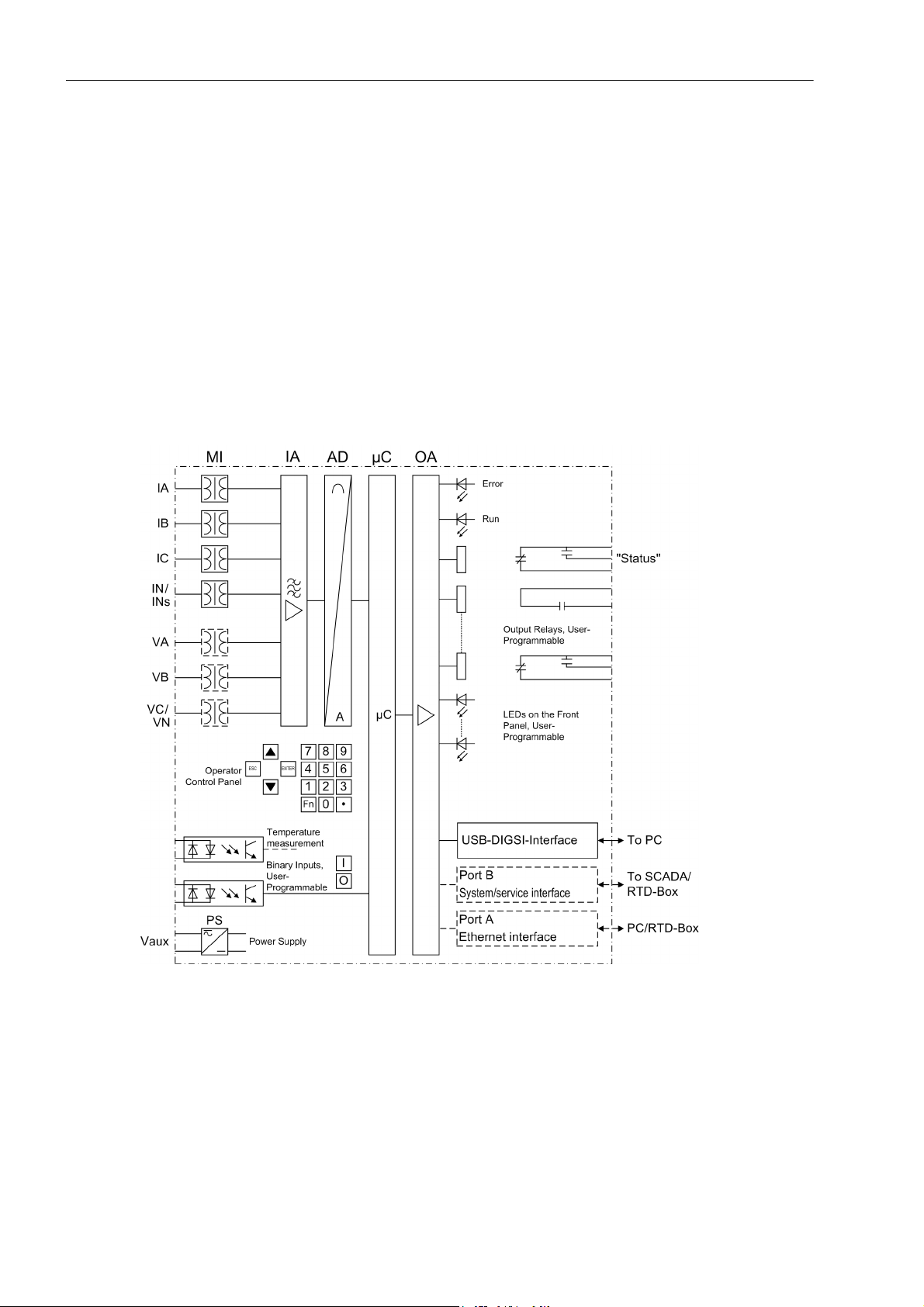
Figure 1-1 shows the basic structure of the 7SK80.
Analog Inputs
The measuring inputs (MI) convert the currents and voltages coming from the measuring transformers and
adapt them to the level appropriate for the internal processing of the device. The device provides 4 current
transformers and - depending on the model - additionally 3 voltage transformers. Three current inputs serve for
the input of the phase currents, another current input (I
I
(current transformer neutral point) or for a separate ground current transformer (for sensitive ground fault
N
detection I
and directional determination of ground faults ) - depending on the model.
Ns
) may be used for measuring the ground fault current
N
18
Figure 1-1 Hardware structure of the digital 7SK80 motor protection device
The optional voltage transformers can either be used to input 3 phase-to-Ground voltages or 2 phase-to-phase
voltages and the displacement voltage (open delta voltage) or any other voltages. It is also possible to connect
two phase-to-phase voltages in open delta connection.
E50417-G1140-C344-A4, Release date 08.2010
SIPROTEC, 7SK80, Manual

The analog input quantities are passed on to the input amplifiers (IA). The input amplifier IA element provides
a high-resistance termination for the input quantities. It consists of filters that are optimized for measured-value
processing with regard to bandwidth and processing speed.
The analog-to-digital (AD) transformer group consists of a an analog-to-digital converter and memory components for the transmission of data to the microcomputer.
Microcomputer System
Apart from processing the measured values, the microcomputer system (μC) also executes the actual protection and control functions. They especially include:
• Filtering and preparation of the measured quantities
• Continuous monitoring of the measured quantities
• Monitoring of the pickup conditions for the individual protective functions
• Interrogation of limit values and sequences in time
• Control of signals for the logic functions
• Output of control commands for switching devices
• Recording of messages, fault data and fault values for analysis
• Management of the operating system and the associated functions such as data recording, real-time clock,
communication, interfaces, etc.
• The information is distributed via output amplifiers (OA).
Introduction
1.1 Overall Operation
Binary Inputs and Outputs
Binary inputs and outputs to and from the computer system are relayed via the input/output modules. The computer system obtains the information from the system (e.g. remote resetting) or the external equipment (e.g.
blocking commands). Outputs are, in particular, commands to the switchgear units and annunciations for
remote signalling of important events and statuses.
Front Elements
Information such as messages related to events, states, measured values and the functional status of the
device are visualized by light-emitting diodes (LEDs) and a display screen (LCD) on the front panel.
Integrated control and numeric keys in conjunction with the LCD enable interaction with the remote device.
These elements can be used to access the device for information such as configuration and setting parameters.
Similarly, setting parameters can be accessed and changed if needed.
In addition, control of circuit breakers and other equipment is possible from the front panel of the device.
Interfaces
Communication with a PC can be implemented via the USB DIGSI interface using the DIGSI software, allowing all device functions to be easily executed.
Communication with a PC is also possible via port A (Ethernet Interface) and port B (System Interface EN 100)
using DIGSI.
Port A or port B can be used for connecting a thermobox - via Ethernet - to enter external temperatures (e.g.
overload protection). Optionally, up to 5 temperature sensors can be connected directly to the device via the
I/O 2 extension module.
In addition to the device communication via DIGSI, port B can also be used to transmit all device data to a
central evaluator or a control center. This interface may be provided with various protocols and physical transmission schemes to suit the particular application.
SIPROTEC, 7SK80, Manual
E50417-G1140-C344-A4, Release date 08.2010
19

Introduction
1.1 Overall Operation
Power Supply
A power supply unit (Vaux or PS) delivers power to the functional units using the different voltage levels. Voltage
dips may occur if the voltage supply system (substation battery) becomes short-circuited. Usually, they are
bridged by a capacitor (see also Technical Data).
A buffer battery is located under the flap at the lower end of the front cover.
20
E50417-G1140-C344-A4, Release date 08.2010
SIPROTEC, 7SK80, Manual

1.2 Application Scope
The digital motor protection SIPROTEC 4 7SK80 is suitable as protection and monitoring unit for asynchronous
machines of any size. It can nevertheless also be used in busbar feeders or as line protection in networks with
grounded, low-resistance grounded, isolated or compensated star point structure. It is suited for networks that
are radial and supplied from a single source, open or closed looped networks and for lines with sources at both
ends.
The device includes the functions that are usually necessary for protection, monitoring of circuit breaker positions and control of circuit breakers; therefore, the device can be employed universally. The device provides
excellent backup facilities of differential protective schemes of any kind for lines, transformers, generators,
motors, and busbars of all electromotive series.
Protection Functions
The basic function is the motor protection with start-up time monitoring, restart inhibit and load step function.
Additionally, there is a non-directional overcurrent protection with three definite time elements each and one
inverse time Element for the phase currents and the ground current. For the inverse time Elements, several
characteristics of different standards are provided. Alternatively, a user-defined Curve can be used for the sensitive ground fault detection.
Introduction
1.2 Application Scope
Further protection functions included are the negative sequence protection, overload protection, circuit breaker
failure protection and ground fault protection.
Depending on the ordered variant, further protection functions are included, such as frequency protection, overvoltage and undervoltage protection, and ground fault protection for high-resistance ground faults (directional
or non-directional).
External detectors account for ambient temperatures or coolant temperatures (possibly also by means of an
external thermobox).
Control Functions
The device provides a control function which can be accomplished for activating and deactivating switchgear
via operator buttons, port B, binary inputs and - using a PC and the DIGSI software - via the front interface.
The status of the primary equipment can be transmitted to the device via auxiliary contacts connected to binary
inputs. The present status (or position) of the primary equipment can be displayed on the device, and used for
interlocking or alarm condition monitoring. The number of operating equipment to be switched is limited by the
binary inputs and outputs available in the device or the binary inputs and outputs allocated for the switch position indications. Depending on the primary equipment being controlled, one binary input (single point indication)
or two binary inputs (double point indication) may be used for this process.
The capability of switching primary equipment can be restricted by a setting associated with switching authority
(Remote or Local), and by the operating mode (interlocked/non-interlocked, with or without password request).
Processing of interlocking conditions for switching (e.g. switchgear interlocking) can be established with the aid
of integrated, user-configurable logic functions.
SIPROTEC, 7SK80, Manual
E50417-G1140-C344-A4, Release date 08.2010
21

Introduction
1.2 Application Scope
Messages and Measured Values; Recording of Event and Fault Data
The operational indications provide information about conditions in the power system and the device. Measurement quantities and values that are calculated can be displayed locally and communicated via the serial interfaces.
Device messages can be assigned to a number of LEDs on the front cover (allocatable), can be externally processed via output contacts (allocatable), linked with user-definable logic functions and/or issued via serial interfaces.
During a fault (system fault) important events and changes in conditions are saved in fault protocols (Event Log
or Trip Log). Instantaneous fault values are also saved in the device and may be analized subsequently.
Communication
The following interfaces are available for communication with external operating, control and memory systems.
The USB DIGSI interface on the front cover serves for local communication with a PC. By means of the SIPRO-
®
TEC
4 operating software DIGSI
®
, all operational and evaluation tasks can be executed via this operator in-
terface, such as the specification and modification of configuration parameters and settings, configuration of
user-specific logic functions, read-out of operational and fault messages as well as measured values, read-out
and displaying of fault records, inquiry of device conditions and measured values, issuing of control commands.
Depending on the ordered variant, additional interfaces are located at the bottom of the device. They serve for
establishing extensive communication with other digital operating, control and memory components:
Port A serves for DIGSI communication directly on the device or via a network.
Furthermore, the connection of one or two thermoboxes for entering external temperatures can be provided via
port A (via Ethernet) or port B, e.g. via RS485.
Port B serves for central communication between the device and a control center. It can be operated via data
lines or fiber optic cables. For the data transfer, there are standard protocols in accordance with IEC 60870-5103 available. The integration of the devices into the SINAUT LSA and SICAM automation systems can also
be implemented with this profile.
Alternatively, there are further coupling options possible with PROFIBUS DP and the DNP3.0 and MODBUS
protocols. If an EN100 module is available, it is also possible to use the IEC61850 protocol.
22
E50417-G1140-C344-A4, Release date 08.2010
SIPROTEC, 7SK80, Manual

1.3 Characteristics
General Characteristics
• Powerful 32-bit microprocessor system.
• Complete digital processing and control of measured values, from the sampling of the analog input quantities to the initiation of outputs, for example, tripping or closing circuit breakers or other switchgear devices.
• Total electrical separation between the internal processing stages of the device and the external transformer,
control, and DC supply circuits of the system because of the design of the binary inputs, outputs, and the
DC or AC converters.
• Complete set of functions necessary for the proper protection of lines, feeders, motors, and busbars.
• Easy device operation through an integrated operator panel or by means of a connected personal computer
running DIGSI.
• Continuous calculation and display of measured and metered values on the front of the device.
• Storage of min/max measured values (slave pointer function) and storage of long-term mean values.
• Recording of event and fault data for the last 8 system faults (fault in a network) with real-time information
as well as instantaneous values for fault recording for a maximum time range of 18 s.
Introduction
1.3 Characteristics
• Constant monitoring of the measured quantities, as well as continuous self-diagnostics covering the hardware and software.
• Communication with SCADA or substation controller equipment via serial interfaces through the choice of
data cable, modem, or optical fibers.
• Battery-buffered clock which can be synchronized via a synchronization signal at the binary input or via a
protocol.
• Switching statistics: Recording of the number of trip signals initiated by the device and logging of currents
switched off last by the device, as well as accumulated short circuit currents of each pole of the circuit breaker.
• Motor Statistics: Recording of the operational information and startup information such as the total number
of motor starts, motor operating hours, percentage of motor operating time, total megawatt hours, and the
startup information duration and currents for each motor startup.
• Operating Hours Counter: Tracking of operating hours of the equipment being protected.
• Commissioning aids such as connection and direction check, status indication of all binary inputs and outputs, easy testing of port B and influencing of information at port B during test operation.
Time Overcurrent Protection 50, 51, 50N, 51N
• Three definite time overcurrent protective Elements and one inverse time overcurrent protective element for
phase current and ground current I
• Allowence of a two-phase (IA, IC) time overcurrent protection;
or summation current 3I0;
N
• For inverse time overcurrent protection, selection from various characteristics of different standards possible.
• Blocking capability e.g. for reverse interlocking with any Element;
• Instantaneous tripping by any overcurrent Element upon switch onto fault is possible;
• In-rush restraint with second harmonic current quantities.
SIPROTEC, 7SK80, Manual
E50417-G1140-C344-A4, Release date 08.2010
23

Introduction
1.3 Characteristics
Ground Fault Protection 50N, 51N
• Three definite time overcurrent protective Elements and one inverse time overcurrent protective element applicable for grounded or high-resistance grounded systems;
• For inverse time overcurrent protection, selection from various characteristics of different standards.
• In-rush restraint with second harmonic current quantities;
• Instantaneous tripping by any overcurrent Element during switch onto fault is possible;
Dynamic Cold Load Pick-up Function 50C, 50NC, 51C, 51NC, 67C, 67NC
• Dynamic changeover of time overcurrent protection settings, e.g. when cold load conditions are recognized;
• Detection of cold load condition via circuit breaker position or current threshold;
• Activation also possible via binary input.
Voltage Protection 27, 59
• Two-element undervoltage detection via system positive sequence voltages, phase-to-phase or phaseground voltages;
• Choice of current supervision for 27-1 and 27-2;
• Separate two-element overvoltage detection of the largest voltages applied or detection of the positive or
negative sequence component of the voltages.
• settable dropout ratio for all elements of the undervoltage and overvoltage protection.
Negative Sequence Protection 46
• Evaluation of negative sequence component of the currents;
• Two definite-time elements 46-1 and 46-2 and one inverse-time element 46-TOC; curves of common standards are available for 46-TOC.
Motor Starting Protection 48
• Inverse time tripping Curve based on an evaluation of the motor starting current;
• Definite time delay for blocked rotor.
Motor Restart Inhibit 66, 86
• Approximate replica of excessive rotor temperature;
• Startup is permitted only if the rotor has sufficient thermal reserves for a complete startup;
• Disabling of the start inhibit is possible if an emergency startup is required.
Load Step Function
24
• Detection of mechanical or thermal overload of the rotor.
E50417-G1140-C344-A4, Release date 08.2010
SIPROTEC, 7SK80, Manual

Frequency Protection 81 O/U
• Monitoring on underfrequency (f<) and/or overfrequency (f>) with 4 frequency limits and delay times that are
independently adjustable;
• Insensitive to harmonics and abrupt phase angle changes;
• Adjustable undervoltage threshold.
Thermal Overload Protection 49
• Thermal profile of energy losses (overload protection has total memory capability);
• True r.m.s. calculation;
• Adjustable thermal alarm level;
• Adjustable alarm level based on current magnitude;
• Additional time constant setting for motors to accommodate the motor at standstill;
• Integration of the ambient temperature or coolant temperature is possible via internal temperature detection
or an external thermobox.
Monitoring Functions
Introduction
1.3 Characteristics
• Reliability of the device is greatly increased because of self-monitoring of the internal measurement circuits
as well as the hardware and software.
• Fuse failure monitor with protection function blocking.
• Monitoring of the current transformer and voltage transformer secondary circuits using summation and symmetry monitoring with optional protection function blocking.
• Trip circuit monitoring;
• Phase rotation check.
Ground Fault Detection 50N(s), 51N(s), 67N(s), 59N/64
• Displacement voltage is measured or calculated from the three phase voltages;
• Determination of a faulty phase on ungrounded or grounded systems;
• Two-element Ground Fault Detection: High-set element 50Ns-2 and overcurrent element 50Ns-1.
• High sensitivity (as low as 1 mA);
• Overcurrent element with definite time or inverse time delay;
• For inverse time overcurrent protection, a user-defined characteristic is available.
• Direction determination with zero sequence quantities(I
tion;
• A sector characteristics can be set as directional characteristic.
, V0), wattmetric ground fault direction determina-
0
• Any Element can be set as directional or non-directional — forward sensing directional, or reverse sensing
directional;
• Optionally applicable as additional ground fault protection.
SIPROTEC, 7SK80, Manual
E50417-G1140-C344-A4, Release date 08.2010
25

Introduction
1.3 Characteristics
Breaker Failure Protection 50 BF
• Checking current flow and/or evaluation of the circuit breaker auxiliary contacts;
• Initiated by the tripping of any integrated protective element that trips the circuit breaker;
• Initiation possible via a binary input from an external protective device.
Flexible Protective Functions
• Up to 20 protection functions which can be set individually to operate in three-phase or single-phase mode;
• Any calculated or directly measured value can be evaluated on principle;
• Standard protection logic with a constant (i.e. independent) characteristic curve.
• Internal and configurable pickup and dropout delay;
• Modifiable message texts.
Thermoboxes/Temperature Detection
• Detection of any ambient temperatures or coolant temperatures with the help of external thermoboxes or
internal temperature detection via the extension module I/O 2.
Phase Rotation
• Selectable ABC or ACB by setting (static) or binary input (dynamic).
Circuit-Breaker Maintenance
• Statistical methods to help adjust maintenance intervals for CB contacts according to their actual wear;
• Several independent subfunctions were implemented (ΣI procedure, ΣI
procedure).
• Acquisition and conditioning of measured values for all subfunctions operates phase-selective using one
procedure-specific threshold per subfunction.
User Defined Functions
• Internal and external signals can be logically combined to establish user-defined logic functions;
• All common Boolean operations are available for programming (AND, OR, NOT, Exclusive OR, etc.);
• Time delays and limit value interrogation;
• Processing of measured values, including zero suppression, adding a knee curve for a transducer input, and
live-zero monitoring;
Breaker Control
• Circuit breakers can be opened and closed manually via specific control keys, programmable function keys,
port B (e.g. by SICAM
x
procedure, 2P procedure and I2t
®
or LSA), or via the operator interface (using a PC and the DIGSI® software).
26
• Circuit breakers are monitored via the breaker auxiliary contacts;
• Plausibility monitoring of the circuit breaker position and check of interlocking conditions.
■
E50417-G1140-C344-A4, Release date 08.2010
SIPROTEC, 7SK80, Manual

Functions 2
This chapter describes the numerous functions available on the SIPROTEC 4 device 7SK80. It shows the
setting possibilities for each function in maximum configuration. Information with regard to the determination of
setting values as well as formulas, if required, are also provided.
Based on the following information, it can also be determined which of the provided functions should be used.
2.1 General 28
2.2 Overcurrent Protection 50, 51, 50N, 51N 55
2.3 Directional Ground Overcurrent Protection 67N 80
2.4 Dynamic Cold Load Pickup 95
2.5 Voltage Protection 27, 59 101
2.6 Negative Sequence Protection 46 112
2.7 Motor Protection (Motor Starting Protection 48, Motor Restart Inhibit 66, Load Jam Protection) 120
2.8 Frequency Protection 81 O/U 143
2.9 Thermal Overload Protection 49 147
2.10 Monitoring Functions 157
2.11 Ground Fault Protection 64, 67N(s), 50N(s), 51N(s) 178
2.12 Breaker Failure Protection 50BF 200
2.13 Flexible Protection Functions 206
2.14 Reverse-Power Protection Application with Flexible Protection Function 219
2.15 Temperature Detection via RTD Boxes 227
2.16 Phase Rotation 238
2.17 Function Logic 240
2.18 Auxiliary Functions 242
2.19 Breaker Control 270
2.20 Notes on Device Operation 282
SIPROTEC, 7SK80, Manual
E50417-G1140-C344-A4, Release date 08.2010
27

Functions
2.1 General
2.1 General
The settings associated with the various device functions may be modified using the operating or service interface in DIGSI in conjunction with a personal computer. Some parameters may also be changed using the controls on the front panel of the device. The procedure is set out in detail in the SIPROTEC System Description /1/.
2.1.1 Functional Scope
The 7SK80 relay comprises protection functions and additional functions. The hardware and firmware is designed for this scope of functions. Additionally, the control functions can be matched to the system requirements. Individual functions can be activated or deactivated during the configuration procedure or the interaction
of functions be modified.
2.1.1.1 Description
Setting the Functional Scope
The available protection and additional functions must be configured as Enabled or Disabled. Some functions allow the user to select among several alternatives which are described further below.
Functions configured as Disabled are not processed by the 7SK80. There are no indications, and the corresponding settings (functions, limit values) are not relevant during configuration.
Note
Available functions and default settings are depending on the ordering code of the relay (see A.1 for details).
2.1.1.2 Setting Notes
Setting the Functional Scope
Your protection device is configured using the DIGSI software. Connect your personal computer either to the
USB port on the device front or to port A or port B on the bottom side of the device depending on the device
version (ordering code). The operation via DIGSI is explained in the SIPROTEC 4 System Description.
The Device Configuration dialog box allows you to adjust your device to the specific system conditions.
Password no. 7 is required (for parameter set) for changing configuration parameters in the device. Without the
password the settings can only be read but not edited and transmitted to the device.
28
E50417-G1140-C344-A4, Release date 08.2010
SIPROTEC, 7SK80, Manual

Special Features
Most settings are self-explaining. The special cases are described in the following.
If you want to use the setting group change function, set address 103 Grp Chge OPTION to Enabled. In this
case, you can select up to four different groups of function parameters between which you can switch quickly
and conveniently during operation. Only one setting group can be used when selecting the option Disabled.
For the elements associated with non-directional overcurrent protection 50(N), 51(N) (phase and ground),
various tripping characteristics can be selected at addresses 112 Charac. Phase and 113 Charac.
Ground. If only the definite time Curve is desired, select Definite Time. Alternatively, you can select
between inverse-time curves according to IEC standard (TOC IEC) or ANSI standard (TOC ANSI). The dropout
behavior of the IEC and ANSI curves is specified at address 1210 or 1310 when configuring the time overcurrent protection.
Set to Disabled to disable the entire time overcurrent protection.
The direction overcurrent protection Ground is set at 11667N/67N-TOC. Here, the same options are available
as for non-directional overcurrent protection (except the 50N-3 element).
For (sensitive) ground fault detection address 130 S.Gnd.F.Dir.Ch lets you specify the directional characteristic of the sensitive ground fault detection. You can select between cos ϕ / sin ϕ and V0/I0 ϕ mea.
as the measurement procedure. The cos ϕ / sin ϕ procedure (via residual wattmetric current detection) is
set by default.
Functions
2.1 General
If cos ϕ / sin ϕ is configured as the measurement procedure, you can select between a definite time curve
(Definite Time) and a User Defined PU at address 131 Sens. Gnd Fault. The setting V0/I0 ϕ
mea.
provides the definite time characteristic Definite Time. When set to Disabled, the entire function is
disabled.
For unbalanced load protection, address 140 46 allows you to specify which tripping characteristics to use. You
can select between Definite Time, TOC ANSI or TOC IEC. If this function is not required, select Disabled.
For overload protection, you can determine at address 142 49 whether the function operates with or without
ambient temperature (With amb. temp. or No ambient temp) or whether the entire function is Disabled.
In address 170 you can set the breaker failure protection to Enabled or Disabled. The setting option
enabled w/ 3I0> subjects the ground current and the negative sequence current to a plausibility check.
For the CB maintenance functions, several options are available under address 172 52 B.WEAR MONIT. Ir-
respective of this, the basic functionality of the summation current formation (ΣI procedure) is always active. It
requires no further configurations and adds up the tripping currents of the trips initiated by the protection functions.
When selecting the ΣI
x
-Procedure, the sum of all tripping current powers is formed and output as reference
value. The 2P Procedure continuously calculates the remaining lifespan of the circuit breaker.
With the I
2
t Procedure the square fault current integrals are formed via arc time and output as a reference
value.
Further information concerning the individual procedures of the CB maintenance are given in Section 2.18.2.
You can also disable this function by setting it to Disabled.
Under address 182 74 Trip Ct Supv it can be selected whether the trip-circuit supervision works with two
(2 Binary Inputs) or only one binary input (1 Binary Input), or whether the function is configured
Disabled.
If you set the function to Enabled in address 190 RTD INPUT, you can specify the number and the transmission type of the measuring points (RTD = Resistance Temperature Detector) in address 191 RTD
CONNECTION. When connecting an RTD box to serial port B, select 6 RTD simplex or 6 RTD HDX; for two
RTD boxes select 12 RTD HDX. When connecting an RTD box to port A, select 6 RTD Eth, for two RTD
boxes select 12 RTD Eth. If the connection is made via the I/O2 module, select the setting Int.Temp.Meas..
The Appendix provides some implementation examples in the section „Connection Examples“). The settings in
address have to comply with those at the RTD box (see Section 2.15.2, at „RTD Box Settings“).
SIPROTEC, 7SK80, Manual
E50417-G1140-C344-A4, Release date 08.2010
29

Functions
2.1 General
In address 192 Cap. Volt.Meas. you can specify whether you want to employ capacitive voltage measure-
ment. When selecting YES, you have to specify the bushing capacitance, the line and stray capacitance for the
capacitive voltage dividers at the voltage inputs in addresses 241 to 246 (see 2.1.3.2).
With capacitive voltage measurement several functions are not available or only partly. See table 2-1 in section
2.1.3.2 for more information regarding this topic.
In address 617 ServiProt (CM) you can specify for which purpose port B is used. T103 means that the
device is connected to a control and protection facility via serial port, DIGSI means that you are using the port
to connect DIGSI and RTD-RS485 means that you are using the port to connect an RTD box. Disabled indicates that you can not use port B.
The flexible protection functions can be configured via parameter FLEXIBLE FUNC.. You can create up to 20
flexible functions by setting a checkmark in front of the desired function (an example is given in the section
2.14). If the checkmark of a function is removed, all settings and configurations made previously will be lost.
After re-selecting the function, all settings and configurations are in default setting. Setting of the flexible function is done in DIGSI under „Settings“, „Additional Functions“ and „Settings“. The configuration is done, as
usual, under „Settings“ and „Masking I/O (Configuration Matrix)“.
2.1.1.3 Settings
Addr. Parameter Setting Options Default Setting Comments
103 Grp Chge OPTION Disabled
Disabled Setting Group Change Option
Enabled
104 OSC. FAULT REC. Disabled
Enabled Oscillographic Fault Records
Enabled
112 Charac. Phase Disabled
Definite Time 50/51
Definite Time
TOC IEC
TOC ANSI
113 Charac. Ground Disabled
Definite Time 50N/51N
Definite Time
TOC IEC
TOC ANSI
116 67N/67N-TOC Disabled
Definite Time 67N, 67N-TOC
Definite Time
TOC IEC
TOC ANSI
117 Coldload Pickup Disabled
Disabled Cold Load Pickup
Enabled
122 InrushRestraint Disabled
Disabled 2nd Harmonic Inrush Restraint
Enabled
130 S.Gnd.F.Dir.Ch cos ϕ / sin ϕ
V0/I0 ϕ mea.
131 Sens. Gnd Fault Disabled
cos ϕ / sin ϕ (sens.) Ground fault dir. character-
istic
Disabled (sensitive) Ground fault
Definite Time
User Defined PU
140 46 Disabled
Disabled 46 Negative Sequence Protection
TOC ANSI
TOC IEC
Definite Time
141 48 Disabled
Enabled
Enabled 48 Startup Time Supervision for
Motors
30
E50417-G1140-C344-A4, Release date 08.2010
SIPROTEC, 7SK80, Manual
 Loading...