

Siemens SIPROTEC 7SJ80, SIPROTEC 7SK80 Product Information

SIPROTEC
7SJ80 / 7SK80
V4.6
Product Information
E50417-K1150-C342-A6

Caution
Please observe Notes and Warnings for your own safety in Chapter 2.
Note
This Product Information contains important information about the
SIPROTEC 7SJ80 / 7SK80.
It is part of the product supplied, and the information in it should be
considered more up-to-date than any other information if uncertainties
arise.
Subject to change without prior notice.
Document Release V04.05.01
Edition 07.2010
Siemens Aktiengesellschaft Order No.: E50417-K1150-C342-A6

Table of Contents
1 General 4
2 Notes on Safety 5
3 Statement of Conformity 7
4 Unpacking and Re-packing 8
5 Storage and Transport 9
6 Dimensions 10
7 Installation Notes 13
8 Connection Notes 14
9 Limit Values of Inputs and Outputs 26
10 General Diagrams 29
11 Operating Pre-conditions 39
E50417-K1150-C342-A6, Edition 07.2010
3SIPROTEC 7SJ80 / 7SK80 V4.60, Product Information

1 General
Disclaimer of Liability
Although we have carefully checked the contents of this publication for
conformity with the hardware and software described, we cannot guarantee complete conformity since errors cannot be excluded.
The information provided in this Product Information is checked at regular
intervals and any corrections that might become necessary are included
in the next releases. Any suggestions for improvement are welcome.
Subject to change without prior notice.
Copyright
Copyright © Siemens AG 2010
The reproduction, transmission or use of this document or its contents is
not permitted without express written authority. Offenders will be liable for
damages. All rights, including rights created by patent grant or registration
of a utility model or design, are reserved.
Registered Trademarks
SIMATIC®, SIMATIC NET®, SIPROTEC®, DIGSI®, SIMEAS® , SICAM®
and SINAUT® are registered trademarks of SIEMENS AG. All other product and brand names in this manual might be trademarks, the use of
which by third persons for their purposes might infringe the rights of their
respective owners.
Note:
For further information see
SIPROTEC 7SJ80 V4.60, Manual E50417-G1140-C343,
SIPROTEC 7SK80 V4.60, Manual E50417-G1140-C344,
SIPROTEC System Description E50417-H1176-C151,
ReadMe-USB.pdf for DIGSI V4.82 (www.siprotec.com).
4 SIPROTEC 7SJ80 / 7SK80 V4.60, Product Information
E50417-K1150-C342-A6, Edition 07.2010

2 Notes on Safety
This manual does not constitute a complete catalog of all safety measures
required for operating the equipment (module, device) in question
because special operating conditions might require additional measures.
However, it does contain notes that must be adhered to for your own personal safety and to avoid damage to property. These notes are highlighted
with a warning triangle and different keywords indicating different degrees
of danger:
Danger
means that death, severe injury, or substantial damage to property will
occur if the appropriate safety measures are not taken.
Warning
means that death, severe injury, or substantial damage to property can
occur if the appropriate safety measures are not taken.
Caution
means that minor injury or damage to property can occur if the appropriate
safety measures are not taken.
Caution
means that damage to property can occur if the appropriate safety measures are not taken.
Note
is important information about the project, handling the product, or the part
of the documentation in question, to which special attention must be paid.
E50417-K1150-C342-A6, Edition 07.2010
5SIPROTEC 7SJ80 / 7SK80 V4.60, Product Information

Qualified Personnel
Commissioning and operation of the equipment (module, device) described in this manual must be performed by qualified personnel only. As
used in the safety notes contained in this manual, qualified personnel are
those persons who are authorized to commission, release, ground, and
tag devices, systems, and electrical circuits in accordance with safety
standards.
Use as Prescribed
The equipment (device, module) must not be used for any other purposes
than those described in the Catalog and the Technical Description. If it is
used together with third-party devices and components, these must be
recommended or approved by Siemens.
Correct and safe operation of the product requires adequate transportation, storage, installation, and mounting as well as appropriate use and
maintenance.
During operation of electrical equipment, it is unavoidable that certain
parts of this equipment will carry dangerous voltages. Severe injury or
damage to property can occur if the appropriate measures are not taken:
• Before making any connections at all, ground the equipment at the PE
terminal.
• Hazardous voltages can be present on all switching components con-
nected to the power supply.
• Even after the supply voltage has been disconnected, hazardous vol-
tages can still be present in the equipment (capacitor storage).
• The secondary circles of the current transformer in the system must not
be operated while open.
• The limit values indicated in the manual or the operating instructions
must not be exceeded; that also applies to testing and commissioning.
6 SIPROTEC 7SJ80 / 7SK80 V4.60, Product Information
E50417-K1150-C342-A6, Edition 07.2010
3 Statement of Conformity
This product complies with the directive of the Council of the European
Communities on the approximation of the laws of the Member States
relating to electromagnetic compatibility (EMC Council Directive 2004/
108/EC) and concerning electrical equipment for use within specified
voltage limits (Low-voltage Directive 2006/95/EC).
This conformity has been established by means of tests conducted by
Siemens AG in accordance of the Council Directive in agreement with
the generic standards EN 61000-6-2 and EN 61000-6-4 for the EMC
directives, and with the standard EN 60255-27 for the low-voltage directive.
The device has been designed and produced for industrial use.
The product is conforming to the international standards of the series
IEC 60255 and the German regulation of VDE 0435.
Further
IEEE Std C37.90
This product is UL-certfied with the values as stated in the Technical Data.
file E194016
NOTE concerning battery disposal
The batteries must only be replaced with the same type or a another type
recommended by the manufacturer. Improper replacement involves
explosion hazard. For disposing the batteries it is necessary to observe
the local national / international directives.
E50417-K1150-C342-A6, Edition 07.2010
7SIPROTEC 7SJ80 / 7SK80 V4.60, Product Information

UL-certification conditions
Servicing of the circuitry involving the batteries and replacement of the
lithium batteries shall be done by a trained technician.
Replace Battery with VARTA or Panasonic Cat. Nos. CR 1/2 AA or BR 1/
2 AA only. Use of another Battery may present a risk of fire or explosion.
See manual for safety instructions.
Caution: The battery used in this device may present a fire or chemical
burn hazard if mistreated. Do not recharge, disassemble, heat above
100 °C (212 °F) or incinerate.
Dispose of used battery promptly. Keep away from children.
4 Unpacking and Re-packing
When dispatched from the factory, the equipment is packed in accordance with the guidelines laid down in IEC 60255–21 which specify the
impact resistance of packaging.
This packing shall be removed with care, without force and without the use
of inappropriate tools. The equipment should be visually checked to
ensure that there are no external traces of damage.
Please observe absolutely all notes and hints which may be enclosed in
the packaging.
Before initial energization with supply voltage, or after storage, the relay
shall be situated in the operating area for at least two hours in order to
ensure temperature equalization and to avoid humidity influences and
condensation.
8 SIPROTEC 7SJ80 / 7SK80 V4.60, Product Information
E50417-K1150-C342-A6, Edition 07.2010

5 Storage and Transport
SIPROTEC® relays should be stored in dry and clean rooms. The limit
temperature range for storage of the relays or associated spare parts is
−25 °C to +55 °C, corresponding to −13 °F to 131 °F.
The relative humidity must be within limits such that neither condensation
nor ice forms.
It is recommended to reduce the storage temperature to the range
+10 °C to +35 °C (50 °F to 95 °F); this prevents early ageing of the
electrolytic capacitors which are contained in the power supply.
For very long storage periods, it is recommended to connect the relay to
the auxiliary voltage source for one or two days every other year, in order
to regenerate the electrolytic capacitors. The same is valid before the
relay is finally installed.
For further transport, the transport packing can be re-used when applied
in the same way. The storage packing of the individual relays is not suited
for transport. If alternative packing is used, this must also provide the
same degree of protection against mechanical shock and vibration as laid
down in IEC 60255–21–1 class 1 and IEC 60255–21–2 class 1.
The Lithium-batteries in our equipment are subject to Special Provision
188 of the UN Recommendations on the Transport of Dangerous Goods
Model Regulations and Special Provision A45 of the IATA Dangerous
Goods Regulation and the ICAO Technical Instructions. This is only valid
for the original battery or original spare batteries.
E50417-K1150-C342-A6, Edition 07.2010
9SIPROTEC 7SJ80 / 7SK80 V4.60, Product Information
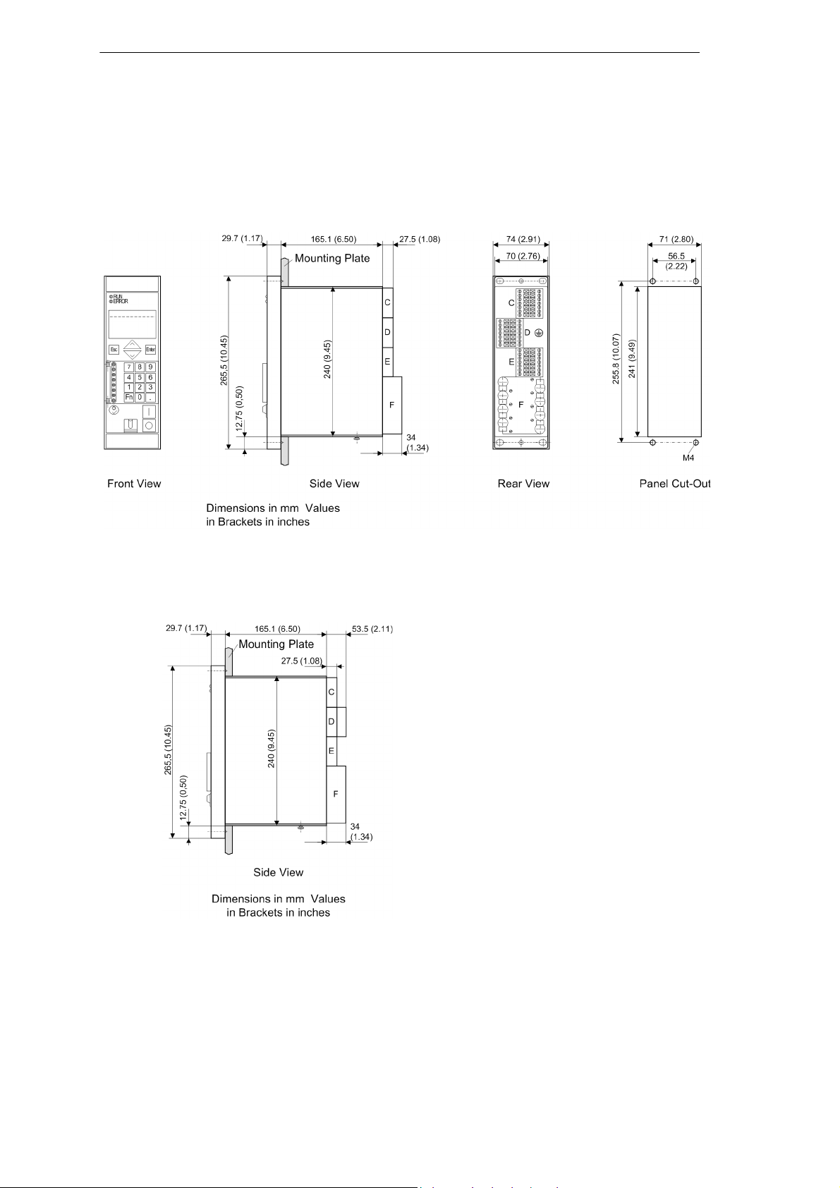
6 Dimensions
Figure 1 Dimensional drawing of a 7Sx80 for panel flush or cubicle
mounting (housing size 1/6)
Figure 2 Dimensional drawing of a 7SK80 (Terminalblock "D" with cap)
10 SIPROTEC 7SJ80 / 7SK80 V4.60, Product Information
E50417-K1150-C342-A6, Edition 07.2010
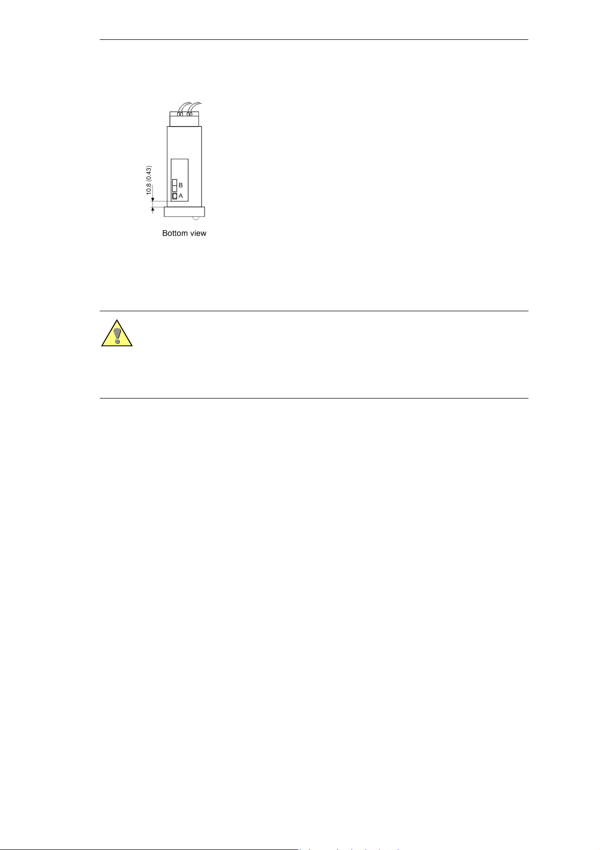
Figure 3 Bottom view of a 7Sx80 (housing size 1/6)
Caution
An angle strip set (contains upper and lower mounting brackets) (OrderNo. C73165-A63-D200-1) is necessary to install the device in a rack.
Using the Ethernet interface it might be necessary to rework the lower
mounting bracket.
E50417-K1150-C342-A6, Edition 07.2010
11SIPROTEC 7SJ80 / 7SK80 V4.60, Product Information
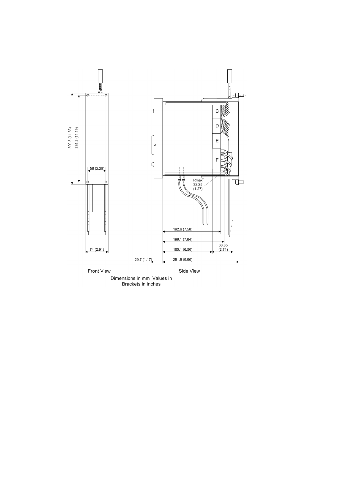
Figure 4 Dimensional drawing of a 7Sx80 for panel flush mounting
(housing size 1/6)
12 SIPROTEC 7SJ80 / 7SK80 V4.60, Product Information
E50417-K1150-C342-A6, Edition 07.2010
7 Installation Notes
Housing for installation in panels, racks, or cubicles
Remove the 2 covers at the top and bottom of the front cover. Thus, 4
elongated holes are revealed in the mounting bracket and can be
accessed.
Insert the device into the panel cut-out and fasten it with four screws.
Mount the 2 covers again.
Connect a solid low-ohmic protective and operational ground to the
grounding terminal of the device. The cross-section of the cable used
must correspond to the maximum connected cross-section but must be at
least 2.5 mm2.
Caution
The printed circuit boards of digital equipment contain CMOS circuits.
These shall not be withdrawn or inserted under live conditions! The modules must be so handled that any possibility of damage due to static electrical charges is excluded. During any necessary handling of individual
modules or printed circuit boards the recommendations relating to the
handling of electro-statically endangered components (EEC) must be
observed. In installed conditions, the modules are in no danger.
UL-certification conditions
Field Wires of Control Circuits shall be separated from other circuits with
respect to the end use requirements!
E50417-K1150-C342-A6, Edition 07.2010
13SIPROTEC 7SJ80 / 7SK80 V4.60, Product Information
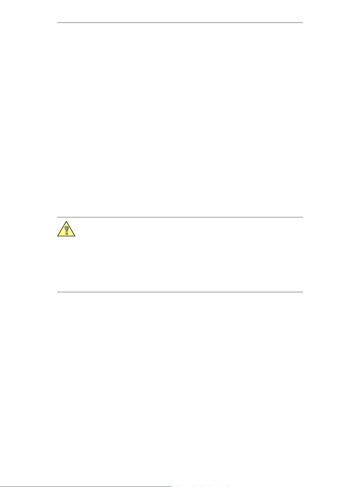
8 Connection Notes
The device provides screw terminals for field wiring. Additionally, serial
interfaces may be present which are to be connected by wires or by optical fiber.
Screw-type terminals on connection modules
The following connectors may exist:
Connection modules for currents, 8-pole,
Connection modules for voltages, 14-pole,
Figure 5 Current and voltage terminal
14 SIPROTEC 7SJ80 / 7SK80 V4.60, Product Information
E50417-K1150-C342-A6, Edition 07.2010
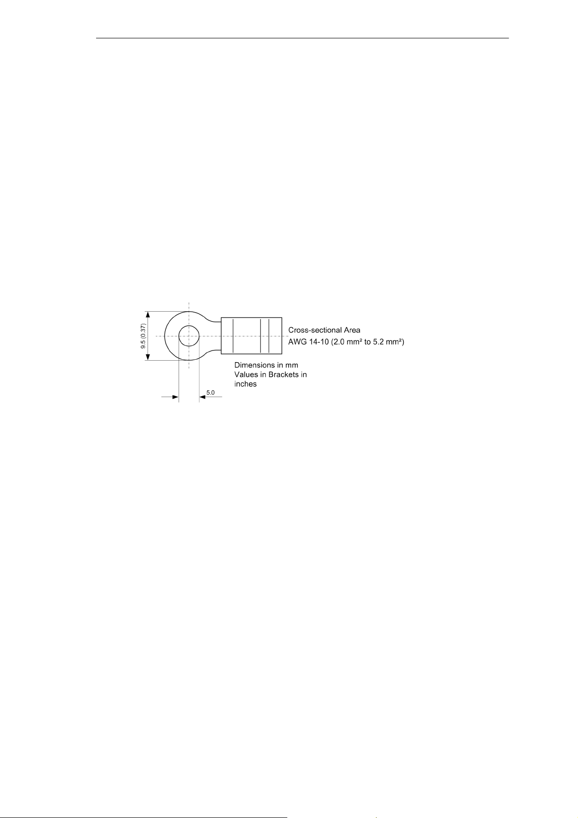
Connections of the Current Terminals
Fixing Elements
The fixing elements for the transformer connection are part of the current
terminal (housing side). The head shape of the terminal screw allows for
using a flat screwdriver (5.5 mm x 1.0 mm / 0.21 in x 0.039 in) or a crosstip
screwdriver (PZ2). PZ2 is recommended.
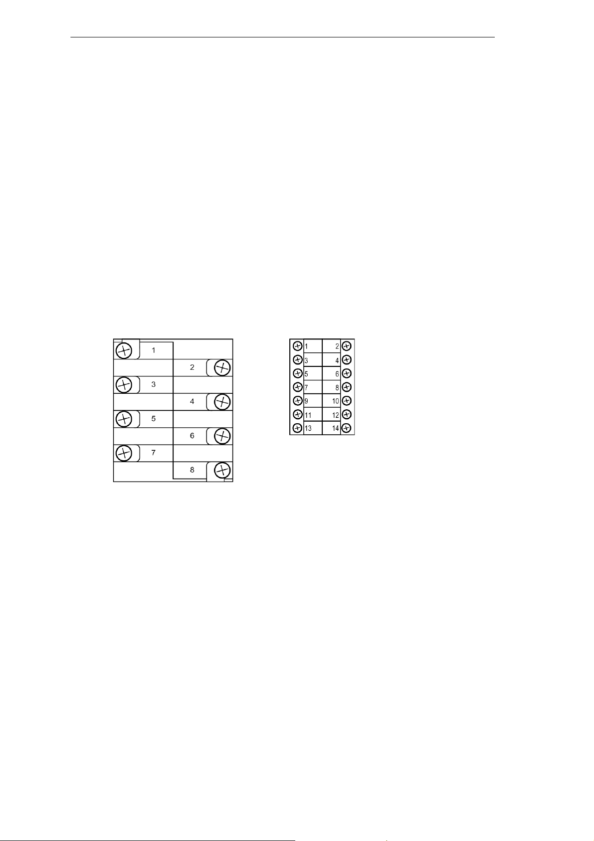
Cable lugs and Wire Cross-sections
There are two connection options: the connection of single wires and the
connection with a ring lug. Only copper wires may be used.
We recommend ring lugs with the following dimensions:
Figure 6 Ring lug
For complying with the required insulation clearances, insulated ring lugs
have to be used. Otherwise, the crimp zone has to be insulated with corresponding means (e.g. by pulling a shrink-on sleeve over).
We recommend ring lugs of the PIDG range from Tyco Electronics.
Two ring lugs can be mounted per connection.
E50417-K1150-C342-A6, Edition 07.2010
15SIPROTEC 7SJ80 / 7SK80 V4.60, Product Information
Figure 7 Current transformer connection
As single wires, solid conductors as well as stranded conductors with conductor sleeves can be used. Up to two single wires with identical crosssections can be used per connection.
Alternatively, short circuit links (Order no. C53207-A406-D193-1) can be
used for vertically arranged terminal points. If short circuit links are used,
only ring lugs are permitted.
When connecting single wires, the following cross-sections are allowed::
Wire cross-section: AWG 14-10
Conductor sleeve with plastic sleeve L = 10 mm (0.39 in) or
Stripping length:
(when used without conductor sleeve)
Mechanical Requirements
The fixing elements and the connected components are designed for the
following mechanical requirements:
(2.0 mm2 to 5.2 mm2)
L = 12 mm (0.47 in)
15 mm (0.59 in)
Only solid copper wires
may be used.
Permissible tightening torque at the terminal
screw
2.7 Nm (23.9 lb.in.)
With solid conductors the
allowed maximum tightening torque is 2 Nm.
Permissible traction per connected conductor
16 SIPROTEC 7SJ80 / 7SK80 V4.60, Product Information
80 N based on IEC 609471 (VDE 660, Part 100)
E50417-K1150-C342-A6, Edition 07.2010
Connections of the Voltage Terminals
Fixing Elements
The fixing elements for the voltage transformer connection are part of the
voltage terminal (housing side). They have a stress-crack- and corrosionresistant alloy. The head shape of the terminal screw allows for using a
flat screwdriver (4.0 mm x 0.8 mm / 0.16 in x 0.031 in) or a crosstip screwdriver (PZ1). PZ1 is recommended.
Cable lugs and Wire Cross-sections
The connection mode available is the connection as single wire. As single
wires, solid conductors as well as stranded conductors with or without
conductor sleeves can be used. For the connection of two single wires we
recommend to use twin connector sleeves. We recommend twin connector sleeves of the PN 966 144 range from Tyco Electronics.
When connecting single wires, the following cross-sections are allowed:
Wire cross-sections: AWG 20-14
Conductor sleeve with plastic sleeve L = 10 mm (0.39 in) or
(0.5 mm2 to 2.0 mm2)
L = 12 mm (0.47 in)
Stripping length:
(when used without conductor sleeve)
With vertically arranged terminal points, single conductors and short circuit links (order no. C53207-A406-D194-1) can be connected together.
Make sure that the short circuit links are connected in alternate sides.
Mechanical Requirements
The fixing elements and the connected components are designed for the
following mechanical requirements:
Permissible tightening torque at the terminal
screw
Permissible traction per connected conductor
12 mm (0.47 in)
Only copper wires may be
used.
1.0 Nm (8.85 lb.in.)
50 N based on IEC 609471 (VDE 660, Part 100)
E50417-K1150-C342-A6, Edition 07.2010
17SIPROTEC 7SJ80 / 7SK80 V4.60, Product Information

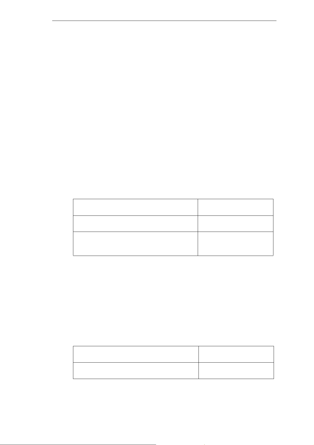
Connection of the temperature sensors
Remove the external insulation from the shielded cable over a length of
approx. 7 cm (2.8 in).
Cut the cable shielding to approx. 4 cm in length and protect the open end
by means of a shrink tube, insulating tape or a similar material. Make sure
that the approx. 1 cm (0.39 in) of the shielding remains open for the
grounding.
Remove the internal insulation of the signaling leads over a length of
approx. 1 cm (0.39 in).
Crimp appropriate conductor sleeves onto the ends of the inner conductors.
Guide the cables through the openings of the shield cap and then connect
the inner conductors as shown in the wiring diagram.
Plug the cap onto the voltage terminals.
Clamp the free part of the cable shielding underneath the cable clamp
next to the connector on the shield cap.
Next, plug the complete clamp into the retaining clips on the rear panel.
18 SIPROTEC 7SJ80 / 7SK80 V4.60, Product Information
E50417-K1150-C342-A6, Edition 07.2010
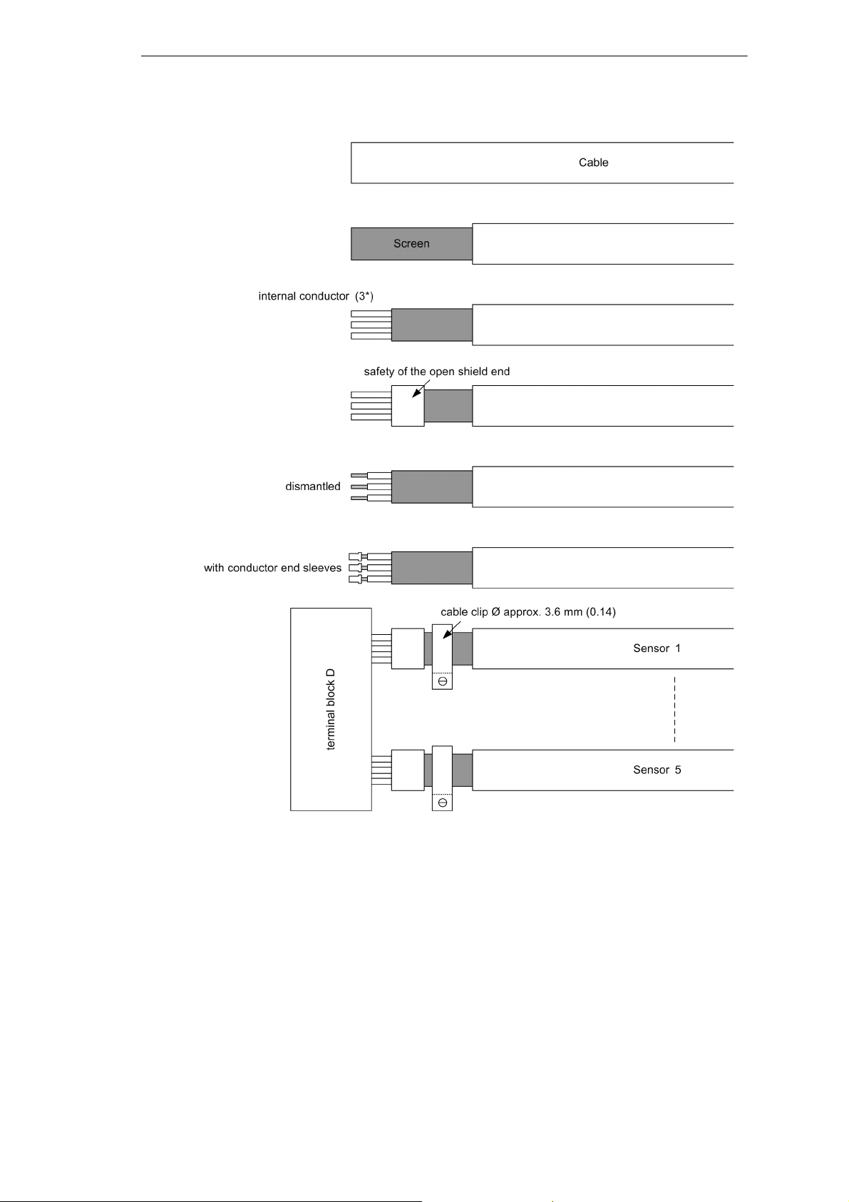
Figure 8 Connection of the cables
E50417-K1150-C342-A6, Edition 07.2010
19SIPROTEC 7SJ80 / 7SK80 V4.60, Product Information
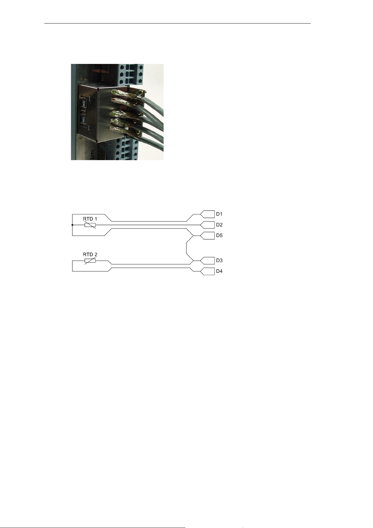
Figure 9 Terminal block “D” with cap
Figure 10 Example: connection of temperature sensor RTD 1 (3-wire
connection) and RTD 2 (2-wire connection) to clip D1 to D5
When using 2-wire connections, short circuit links must be used e.g. for
RTD 2 between D3 and D5.
20 SIPROTEC 7SJ80 / 7SK80 V4.60, Product Information
E50417-K1150-C342-A6, Edition 07.2010
Front USB-interface
USB-interface for the connection between the protection device and the
PC.
Figure 11 USB-interface
Assignment of the USB socket
Pin-No. 1 2 3 4 Housing
USB VBUS
(unused)
D- D+ GND Shield
E50417-K1150-C342-A6, Edition 07.2010
21SIPROTEC 7SJ80 / 7SK80 V4.60, Product Information
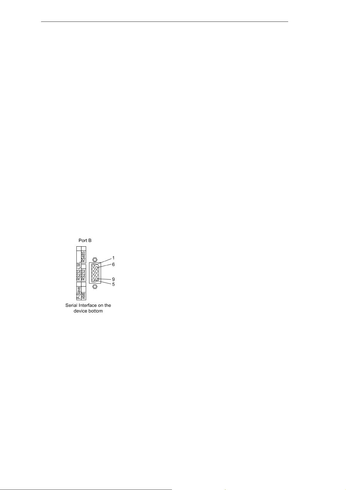
D-Subminiature Sockets (only at optional port B)
9-pin D-subminiature sockets are provided for all electrical communication interfaces Standard 9-pin D-subminiature plug connectors per MIL–
C–24308 and DIN 41652 can be used.
The necessary communication cables are dependent on the interface:
RS232: Three-wire or five-wire, twisted and shielded, e.g. interface
cable 7XV5100–4.
RS 485: Three-wire, twisted and shielded.
Profibus: Two-wire or four-wire, twisted and shielded:
Wire type A according EN 50170/vol. 2 and DIN 19245/part 2,
Wire Resistance: 135 Ω to 165 Ω (f > 100 kHz),
Capacitance: < 48 nF/mile or < 30 nF/km,
Circuit Resistance: < 177 Ω/mile or < 110 Ω/km,
Conductor Diameter: > 0.64 mm,
Conductor Cross-sectional Area: > 0.34 mm2,
e.g. SINEC L2 Industrial Twisted Pair installation wire,
(see catalogue IK 10 “SIMATIC NET, Industrial Communication Networks”).
Figure 12 Nine-pin D-subminiature Connector
22 SIPROTEC 7SJ80 / 7SK80 V4.60, Product Information
E50417-K1150-C342-A6, Edition 07.2010
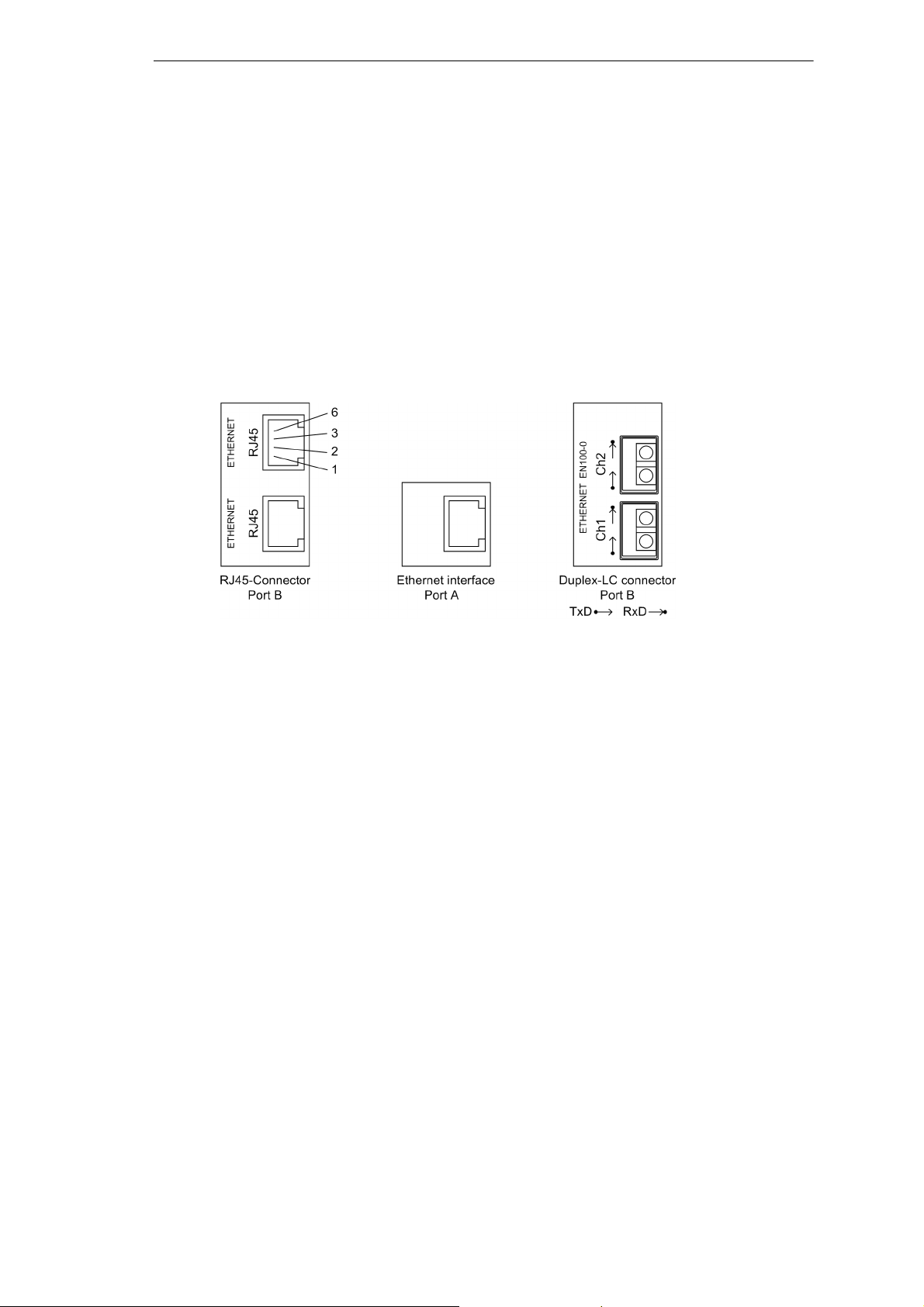
Connections to Ethernet
Two different connection modes per IEEE 802.3 are available:
100Base-T (10/100 TX)
Electrical: RJ45 socket connector
100Base-FL
Optical:Duplex-LC with optical connectors
Select only one of these facilities, you cannot use both at the same time.
The Ethernet interface on port A is only available in the version RJ45.
Figure 13 Ethernet connection – examples
For 100Base-T
Connector Type: RJ45 plug connector as per IEEE 802.3
Cables: CAT 5 (shielded twisted-pair)
For 100Base-FL
Fibre-optic plug type: Duplex-LC
Applicable fibre-type: multimode
G50 µm/125 µm
G62.5µm/125µm
Wave length: λ = approx. 1300 nm
Permissible bending radius: for indoor cables r
for outdoor cables r
= 5 cm (2.0 in)
min
= 20 cm (8.0 in)
min
E50417-K1150-C342-A6, Edition 07.2010
23SIPROTEC 7SJ80 / 7SK80 V4.60, Product Information
Optical Fiber
The optical fiber communication interfaces are provided with caps to
protect the optical components against dust or other contaminants.
Figure 14 Optical Communication Interfaces
Warning!
Laser Radiation! Class 1
Do not look into the fiber–optic elements! .
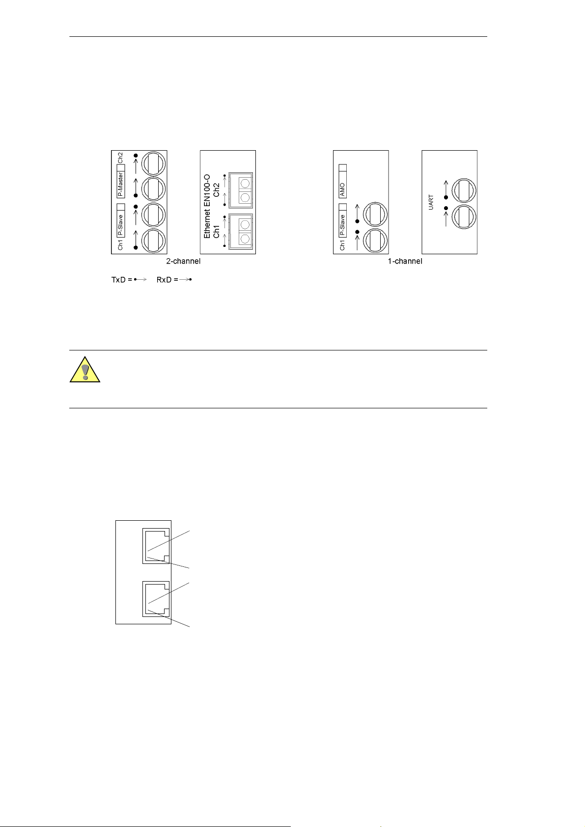
Connections to IEC 60870-5-103 redundant
8-pin RJ45 socket connectors are provided for electrical communication
interface T103 redundant..
2
1
2
Ch1 Ch2
T103 - redundant
RJ45 socket
1
Figure 15 Interface T103 redundant
24 SIPROTEC 7SJ80 / 7SK80 V4.60, Product Information
E50417-K1150-C342-A6, Edition 07.2010
 Loading...