

Siemens SIPROTEC 7SJ62, SIPROTEC 7SA6, SIPROTEC 7SJ61, SIPROTEC 7SJ63, SIPROTEC 7SJ64 User Manual
...
SIPROTEC
Preface
Table of contents
PROFIBUS Communication modules 1
Parameters and properties 2
Protection devices
7SA522, 7SA6
7SD5, 7SD610
7SJ61...7SJ64
7ST622, 7ST61, 7ST63
7UM61, 7UM62
7UT612, 7UT613, 7UT63
7VE61, 7VE63
7VK61
Input/Output unit
6MD63
Data type definitions 3
PROFIBUS-DP - Parameterization in DIGSI 4
Technical data 5
Index
Bay control unit
6MD663/6MD664
Communication module
PROFIBUS-DP
Communication profile
Revision 4.2
Edition: April 2005
C53000-L1840-B001-03

Liability statement
We have checked the contents of this manual against the
hardware and software described. Exclusions and deviations cannot be ruled out; we accept no liability for lack of
total agreement.
The information in this manual is checked periodically,
and necessary corrections will be included in future
editions.
We appreciate any suggested improvements.
We reserve the right to make technical improvements
without notice.
Siemens Aktiengesellschaft
C53000-L1840-B001-03
Copyright
Copyright © Siemens AG 2005. All rights reserved.
Dissemination or reproduction of this document, or evaluation and communication of its contents, is not authorized except where expressly permitted.
Violations are liable for damages. All rights reserved, particularly for the
purposes of patent application or trademark registration.
Registered trademarks
SIPROTEC
are registered trademarks of Siemens AG.
Other designations in this manual may be trademarks that if used by third
parties for their own purposes may violate the rights of the owner.
®
, SIMATIC®, SIMATIC NET ®, SINAUT ®, SICAM® and DIGSI®

Preface
Purpose of this
manual
SIPROTEC4
System Manual
Bus mapping
documentation
The manual describes the functions, bus specific parameters, DIGSI parameterization
and the hardware interface of the PROFIBUS-DP slave of the SIPROTEC devices and
is divided into the following topics:
• PROFIBUS Communication modules → Chapter 1;
• Parameters and properties → Chapter 2;
• Data type definitions → Chapter 3;
• PROFIBUS-DP - Parameterization in DIGSI → Chapter 4;
• Technical data → Chapter 5.
General details about the function, operation, assembly and commissioning of the
SIPROTEC devices you find in the
• SIPROTEC4 System Manual, order no. E50417–H1176–C151.
The following additional manuals inform you about the data in the PROFIBUS-DP
messages of the SIPROTEC devices:
Manual Order number
PROFIBUS-DP - Bus mapping 7UM61 C53000-L1840-B005-03
PROFIBUS-DP - Bus mapping 7SJ61...7SJ64, 6MD63 C53000-L1840-B006-03
PROFIBUS-DP - Bus mapping 7SA522, 7SA6 C53000-L1840-B007-03
PROFIBUS-DP - Bus mapping 7UM62 C53000-L1840-B009-03
PROFIBUS-DP - Bus mapping 7UT612 C53000-L1840-B010-03
PROFIBUS-DP - Bus mapping 6MD663/6MD664 C53000-L1840-B011-03
PROFIBUS-DP - Bus mapping 7VK61 C53000-L1840-B013-03
PROFIBUS-DP - Bus mapping 7SD5, 7SD610 C53000-L1840-B014-03
PROFIBUS-DP - Bus mapping 7UT613, 7UT63 C53000-L1840-B015-03
PROFIBUS-DP - Bus mapping 7ST61, 7ST63 C53000-L1840-B016-03
PROFIBUS-DP - Bus mapping 7VE61, 7VE63 C53000-L1840-B017-03
You can download these manuals
from Internet http://www.siprotec.com
or please contact your Siemens representative.
C53000-L1840-B001-03
3SIPROTEC PROFIBUS-DP - Communication profile

Preview
PROFIBUS-DP
specification
The PROFIBUS-DP specification and the structure of the PROFIBUS-DP messages
are defined in the European Standard EN 50170:
PROFIBUS Specification
Normative Parts of PROFIBUS-FMS, -DP, -PA
According to the European Standard
EN 50170, Volume 2
PROFIBUS Nutzerorganisation e.V.
Validity This manual is valid for the SIPROTEC devices:
• 6MD63 (firmware version 4.40 or higher),
• 6MD663/6MD664 (firmware version 4.20 or higher),
• 7SA522, 7SA6 (firmware version 4.20 or higher),
• 7SD5, 7SD610 (firmware version 4.20 or higher),
• 7SJ61...7SJ64 (firmware version 4.40 or higher),
• 7ST61, 7ST63 (firmware version 4.00 or higher),
• 7ST622 (firmware version 4.00 or higher),
• 7UM61 (firmware version 4.10 or higher),
• 7UM62 (firmware version 4.00 or higher),
• 7UT612 (firmware version 4.00 or higher),
• 7UT613, 7UT63 (firmware version 4.00 or higher),
• 7VE61, 7VE63 (firmware version 4.00 or higher),
• 7VK61 (firmware version 4.00 or higher),
with PROFIBUS communication module up to HW revision 3 and
• PROFIBUS-DP firmware version 02.00.05,
• PROFIBUS-DP firmware version 03.00.03 or higher at use of
• Transformer tap change commands/Transformer tap position indications
(ref. to chap 3.7 and 3.8),
• Event list via PROFIBUS-DP (Sequence of events, ref. to chap. 2.5),
• PROFIBUS-DP firmware version 03.01.03 or higher at use of
• Time synchronization via PROFIBUS-DP with time intervals between time
synchronization messages of less than 1 minute (ref. to chap. 4.4),
• PROFIBUS-DP firmware version 03.04.01 or higher at use of
• PROFIBUS time synchronization messages with local time correction value
(ref. to chap. 4.4.2),
4
SIPROTEC PROFIBUS-DP - Communication profile
C53000-L1840-B001-03

with PROFIBUS communication module from HW revision 4 and
• PROFIBUS-DP firmware version 04.00.06 or higher at use of
• Display of module specific information (ref. to chap. 1.2),
• OLM V3 mode of the PROFIBUS-DP module (ref. to chap. 2.1.2),
• PROFIBUS-DP firmware version 04.01.01 or higher at use of
• PROFIBUS time synchronization messages with local time correction value
(ref. to chap. 4.4.2).
For device parameterization have to be used:
• DIGSI 4.21 considering the preconditions explained in chapter 4.1.3,
• DIGSI 4.30 or higher,
• DIGSI 4.40 or higher at use of
• Transformer tap change commands/Transformer tap position indications
(ref. to chap 3.7 and 3.8),
• PROFIBUS-DP standard mappings 3-1 to 3-n
(n = device type dependent number of standard mappings).
Preview
Additional Support For questions regarding SIPROTEC4 devices, please contact your Siemens repre-
sentative.
Training courses Individual course offerings may be found in our Training Catalog and questions can be
directed to our Training Centre. Please contact your Siemens representative.
Target audience Protection engineers, commissioning engineers, personnel concerned with adjust-
ment, checking and service of selective protective equipment, automatic and control
facilities and personnel of electrical facilities and power plants.
SIPROTEC PROFIBUS-DP - Communication profile
C53000-L1840-B001-03
5

Preview
Warning!
Hazardous voltages are present in this electrical equipment during operation.
Non-observance of the safety rules can result in severe personal injury or property
damage.
Only qualified personnel shall work on and around this equipment after becoming
thoroughly familiar with all warnings and safety notices of this and the associated
manuals as well as with the applicable safety regulations.
The successful and safe operation of this device is dependent on proper transport and
storage, proper handling, installation, operation, and maintenance by qualified personnel under observance of all warnings and hints contained in this and the associated manuals.
In particular the general erection and safety regulations (e.g. IEC, EN, DIN, VDE, or
other national and international standards) regarding the correct use of high-voltage
installations must observed. Non-observance can result in death, personal injury or
substantial property damage.
Typographic and
graphical conventions
QUALIFIED PERSONNEL
For the purpose of this manual and product labels, a qualified person is one who is
familiar with the installation, construction and operation of the equipment and the
hazards involved. In addition, he has the following qualifications:
• Is trained and authorized to energize, de-energize, clear, ground and tag circuits
and equipment in accordance with established safety practices.
• Is trained in the proper care and use of protective equipment in accordance with
established safety practices.
• Is trained in rendering first aid.
The following text formats are used to identify concepts giving device information described by the text flow:
Parameter names, or identifiers for configuration or function parameters that appear
in the device display or on the screen of a PC (with DIGSI) are shown in mono-script
(same point size) bold text. This also applies to header bars for selection menus.
Parameter conditions, or possible settings of parameters that appear in the device display or on the screen of a PC (with DIGSI), are additionally shown in italic style.
This also applies to selection items for selection menus.
„Annunciations“, or identifiers for information produced by the device or required
by other devices or from the switchgear is shown in mono-script (same point size) and
placed into quotation marks.
For diagrams in which the identifier type results from the representation itself, text conventions may differ from the above-mentioned.
6
SIPROTEC PROFIBUS-DP - Communication profile
C53000-L1840-B001-03

Revision index
Listing of the changes between the editions of this manual:
Modified chapters /
pages
general
Chap. 3.1.4
Chap. 3.3.3
Chap. 2.7 - 2.9
Chap 1.1.3
Chap. 1.3.1
Chap. 1.2.2
Chap. 1.5
Chap. 3.2
Chap. 4.2
general
Chap. 3.4.1
general
Chap. 1.1.2
Chap. 3.4.1
Chap. 4.2
Edition Reasons of modification
1.0 First edition, Doc.-No.: C53000-L1840-B001-03
Sept. 17
2.0
3.0
3.1
• Manual is also valid for 6MD63 an 7SJ61...7SJ64 devices
• New chapter “Interface selection and mapping selection in DIGSI 4.3 or
• Description of Scaling indices 7 to 9 added
Jan. 14
• new data type definitions for “Transformer tap change command”, “Trans-
• new chapter “Event list settings”
• Note for setting of tagging “SysIntErr” added
• new chapter “Transformer tap change commands”
• new chapter “Event list via PROFIBUS-DP”
• Type TxTap can be routed to “Destination system interface”
• max. line length for redundant optical rings an baud rates >= 500 kB/s
• Note to parameters “Retry limit” and “Slot time” added
• Manual is also valid for 7UM61 devices with firmware from V4.1
• Time interval for time synchronization of SIPROTEC devices via PROFI-
Sept. 18
• Manual is also valid for 7SD5, 7SD610 devices with firmware from V4.2,
• Notes for fibre-optical settings, Network size: S3 at the OLM/G12 has to
• Time intervals of less than 1 minute for time synchronization of SIPRO-
• Value for “Optical receiver sensitivity” added
Feb. 28
th
, 2001
higher”
th
, 2002
former tap position indication” and “Message block for event list”
corrected
BUS-DP has to be 1 minute
th
, 2002
7UT613, 7UT63 devices with firmware from V4.0 and 7VK61 devices with
firmware from V4.0
be set inversely to the value DP_OLM_NetworkSize
TEC devices are available with PROFIBUS-DP communication module
firmware from V03.01.03
th
, 2003
C53000-L1840-B001-03
7SIPROTEC PROFIBUS-DP - Communication profile

Revision index
Modified chapters /
pages
general
Chap. 1
Chap. 2.1.1
Chap. 2.1.2
Chap. 2.3.2
Chap. 4.4
Chap. 4.5
Chap. 5.2
general
Chap. 1.2.1
Chap. 3.3
Chap. 4.4.2
Chap. 4.4.2 4.2
Edition Reasons of modification
4.0
• Manual is also valid for 7ST61, 7ST63 devices with firmware from V4.0
and 7VE61, 7VE63 devices with firmware from V4.0
• Chap. “PROFIBUS communication modules” added (new HW revision 4),
the following chapter numbers moved up
• Assignment of PNO identification numbers for modules form HW rev. 4;
note to bus silent time after baud rate change added
• Setting of OLM V3 compatible modes for fibre-optical modules from HW
revision 4
• Example for routing of the OLM status indications in DIGSI added
• Precondition for time synchronization: only one master station may send
time messages in the PROFIBUS net
• new Chap. “Using SFC14 and SFC15 in STEP7”
• notes completed with OLM V3 mode and HW revisions and example for
correct parameterization with “Number of OLM” in the DP master added
th
, 2004
4.1
Feb. 5
• Page numbering in the manual now continuous, not chapter-related any
more
• Explanation of the display of the correction values from time synchroniza-
tion messages added
• Meaning of values 0 and 3 for DP, depending on the type, added
• New value ’2’ for GlobalSection.DP_TimeSyncEnable
th
Dec. 8
• New value ’3’ for GlobalSection.DP_TimeSyncEnable
Apr. 14
, 2004
th
, 2005
8
SIPROTEC PROFIBUS-DP - Communication profile
C53000-L1840-B001-03

Table of contents
Preface.................................................................................................................................................. 3
Revision index ..................................................................................................................................... 7
1 PROFIBUS Communication modules .............................................................................................. 11
1.1 Communication module types and hardware revisions........................................................ 12
1.1.1 Communication module types .............................................................................................. 12
1.1.2 Hardware revisions............................................................................................................... 12
1.1.3 Compatibility of the communication module hardware with PROFIBUS-DP firmware versions
and mapping files ................................................................................................................. 13
1.2 Display of module-specific information at the SIPROTEC device ........................................ 15
1.2.1 Block 1: Status and parameters of the PROFIBUS-DP slave .............................................. 17
1.2.2 Block 2: Firmware versions and mapping file ....................................................................... 19
1.2.3 Block 3: Module hardware information and boot firmware version....................................... 20
1.2.4 Block 4: OLM information ..................................................................................................... 21
1.2.5 Block 5: Status of the event list via PROFIBUS-DP ............................................................. 24
2 Parameters and properties ............................................................................................................... 25
2.1 Bus specific parameters ....................................................................................................... 26
2.1.1 PROFIBUS-DP settings........................................................................................................ 26
2.1.2 Configuration of the fibre-optical interface............................................................................ 28
2.1.3 Event list settings ................................................................................................................. 31
2.1.4 PROFIBUS-DP Configuration data....................................................................................... 31
2.2 Execution of switching operations via PROFIBUS-DP ......................................................... 32
2.2.1 Command output modes ...................................................................................................... 32
2.2.2 Transformer tap change commands..................................................................................... 33
2.2.3 Behaviour under special operating conditions...................................................................... 33
2.3 Response in the event of disturbed communication to the PROFIBUS-DP master ............. 34
2.3.1 Communication interruption.................................................................................................. 34
2.3.2 Signalling of line-breaks in a redundant fibre-optical ring..................................................... 35
2.4 Annunciations to the PROFIBUS-DP master ....................................................................... 37
2.5 Event list via PROFIBUS-DP (Sequence of events recorder) .............................................. 38
2.5.1 Properties of the event list.................................................................................................... 39
C53000-L1840-B001-03
9SIPROTEC PROFIBUS-DP - Communication profile

Table of contents
2.5.2 Structure of a PROFIBUS-DP telegram with event list ......................................................... 40
2.5.2.1 Telegram in input direction ................................................................................................... 40
2.5.2.2 Telegram in output direction ................................................................................................. 42
2.5.3 Handshake mechanism ........................................................................................................43
3 Data type definitions.......................................................................................................................... 45
3.1 Single-point indication (SP, Input) ........................................................................................ 46
3.2 Single command (SC, Output).............................................................................................. 47
3.3 Double-point indication (DP, Input) / Double command (DC, Output) .................................. 48
3.4 Measured value (signed integer) .......................................................................................... 49
3.5 Measured value (float) .......................................................................................................... 50
3.6 Metered measurand (unsigned long).................................................................................... 51
3.7 Transformer tap change command (TC) .............................................................................. 52
3.8 Transformer tap position indication (TM).............................................................................. 53
3.9 Message block for event list via PROFIBUS-DP .................................................................. 54
4 PROFIBUS-DP - Parameterization in DIGSI ..................................................................................... 57
4.1 Interface selection and mapping files ................................................................................... 58
4.1.1 Standard mappings 3-1 to 3-n .............................................................................................. 58
4.1.2 Compatibility with standard mappings of previous versions ................................................. 59
4.1.3 Interface selection and mapping selection in DIGSI 4.21 ..................................................... 59
4.1.4 Interface selection and mapping selection in DIGSI 4.3 or higher........................................ 63
4.2 Customization of the allocations ........................................................................................... 66
4.3 Scaling of measured values.................................................................................................. 70
4.3.1 Measurement conversion .....................................................................................................70
4.3.2 Number representation depending on the parameterization ................................................ 71
4.3.3 Parameterization in DIGSI .................................................................................................... 73
4.4 Time synchronization............................................................................................................ 75
4.4.1 PROFIBUS-DP master .........................................................................................................75
4.4.2 Parameterization in DIGSI .................................................................................................... 77
4.5 Using SFC14 and SFC15 in STEP7 ..................................................................................... 79
5 Technical data .................................................................................................................................... 83
5.1 Connection via the PSE module ........................................................................................... 84
5.2 Connection via the PSO module........................................................................................... 86
Glossary.............................................................................................................................................. 89
Index.................................................................................................................................................... 91
10
SIPROTEC PROFIBUS-DP - Communication profile
C53000-L1840-B001-03

PROFIBUS Communication modules 1
This chapter shows the hardware and software necessary for PROFIBUS-DP communication with SIPROTEC devices and describes the display of module-specific information at the device.
1.1 Communication module types and hardware revisions 12
1.2 Display of module-specific information at the SIPROTEC device 15
C53000-L1840-B001-03
11SIPROTEC PROFIBUS-DP - Communication profile

PROFIBUS Communication modules
1.1 Communication module types and hardware revisions
1.1.1 Communication module types
Two communication modules are available for the connection of PROFIBUS-DP to the
SIPROTEC devices:
RS485
bus interface
Fibre-optical
bus interface
Technical data The technical data of the above-mentioned PROFIBUS communication modules are
PROFIBUS module with isolated RS485 interface.
This module also is called PSE module (Communication module PROFIBUS slave
electrical) subsequently.
PROFIBUS module with fibre-optical interface.
An OLM (Optical link module) for electrical to optical conversion of PROFIBUS signals
is integrated on this communication module and two optical channels (each with Send
and Receive) are utilizable.
It is possible to build up PROFIBUS nets in a redundant optical ring topology with that.
This module also is called PSO module (Communication module PROFIBUS slave
fibre-optical) subsequently.
summarized in chap. 5.
1.1.2 Hardware revisions
There exist two different hardware revisions for PROFIBUS communication modules:
• up to HW revision 3:
delivery up to the beginning of year 2004
12
• from HW revision 4:
replacement for modules up to HW revision 3, delivery from beginning of 2004
The communication modules from HW revision 4 are function compatible to the modules up to HW revision 3.
Please note the dependency of the PROFIBUS-DP firmware versions with the HW
revisions described in chap. 1.1.3.
The hardware revision of the PROFIBUS communication modules is also recognizable in build-in condition at the rear of the SIPROTEC device at the labelling of the
communication module mounting bracket:
• up to HW revision 3: identification “P-Slave”
• from HW revision 4: identification “Profibus”
SIPROTEC PROFIBUS-DP - Communication profile
C53000-L1840-B001-03
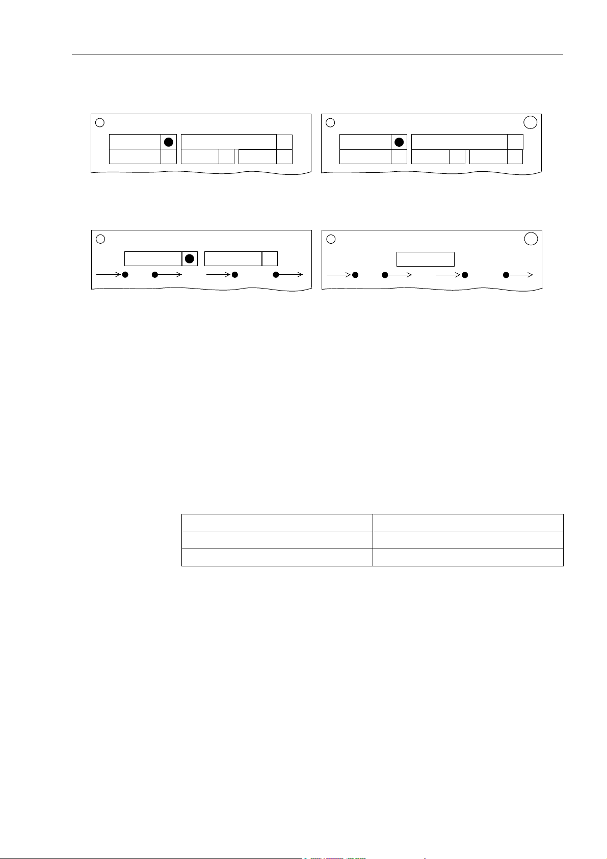
PROFIBUS RS485 (PSE module)
PROFIBUS Communication modules
P-Slave
AME
up to HW revision 3
RS232-LWL
RS232 RS485
Profibus
AME
from HW revision 4
RS232-LWL
RS232 RS485
PROFIBUS fibre-optical, double loop (PSO module)
Ch1
up to HW revision 3
Figure 1-1 HW revisions of the communication modules, labelling of the mounting brackets
P-Slave
P-Master
General details about the assembly of communication modules as well as the setting
of the terminating resistors on the PSE modules you find in the SIPROTEC4 System
Manual (ref. to page 3).
Ch2
Ch1
from HW revision 4
Profibus
Ch2
1.1.3 Compatibility of the communication module hardware with PROFIBUS-DP
firmware versions and mapping files
Hardware and
firmware
Please note the following listed compatibility between the hardware revisions of the
communication modules and the PROFIBUS-DP firmware versions:
Hardware revision Firmware version to be used
up to HW revision 3 up to PROFIBUS-DP firmware V03
from HW revision 4 from PROFIBUS-DP firmware V04
Table 1-1 Hardware revisions and firmware versions
The PROFIBUS-DP firmware for communication modules from HW revision 4 is:
• function compatible with firmware versions for modules up to HW revision 3
(i.e. contains all there contained functionalities),
• offers additional functionalities, e.g.:
• display of module-specific information at the device (ref. to chap. 1.2),
• OLM V3 compatibility mode with fibre-optical modules (ref to chap. 2.1.2).
SIPROTEC PROFIBUS-DP - Communication profile
C53000-L1840-B001-03
13

PROFIBUS Communication modules
Note:
If, during loading of the PROFIBUS-DP firmware on the communication module, a
non-compatible hardware revision is recognized, then the firmware update is cancelled.
Please, in case of an abort of loading the PROFIBUS-DP communication firmware,
check first the dependencies indicated in Table 1-1.
After attempting to load a PROFIBUS-DP firmware version on a non-compatible hardware revision, the SIPROTEC device remains in the loader mode (display = empty,
LED 5 = ON, LED 6 flashing) and loading of a correct firmware version or an initial
reset is expected.
If no firmware shall be loaded in this situation, then the device has to be switched off
an (after at least 3 sec.) switched on again.
The previous firmware configuration is then used furthermore.
Hardware and
mapping files
There is no compatibility reduction between PROFIBUS-DP mapping files of the
SIPROTEC devices and the hardware revision of the communication modules, i.e.:
• the known PROFIBUS-DP mapping files for SIPROTEC devices, offered in DIGSI
and used so far, are used for parameterization furthermore,
• existing parameterizations can be used further, even if a communication module up
to HW revision 3 is replaced by a communication module from HW revision 4 (considering the firmware compatibility in Table 1-1).
14
SIPROTEC PROFIBUS-DP - Communication profile
C53000-L1840-B001-03

PROFIBUS Communication modules
1.2 Display of module-specific information at the SIPROTEC device
Note:
The following prerequisites are necessary for using the functionality “Display of
module-specific information at the SIPROTEC device”:
• PROFIBUS communication module from HW revision 4 with PROFIBUS-DP firm-
ware from V04.00,
• SIPROTEC device firmware which supports this function, e.g.:
• 7SJ61...7SJ64, 6MD63 device firmware from V4.50,
• 6MD663/6MD664 device firmware from V4.50,
• 7SA522, 7SA6 device firmware from V4.50.
Changing parameters for the PROFIBUS-DP slave of the SIPROTEC device is exclusively possible using the DIGSI parameterization system.
If the display of module-specific information is not supported by the firmware of the
used SIPROTEC device then the below-mentioned menu items are not offered for
selection.
If a PROFIBUS communication module up to HW revision 3 is used, then in a SIPROTEC device with above-mentioned firmware V4.50 the following text is displayed in
case of selecting the menu item for display of module-specific information:
**** LIST EMPTY ****
The values in the display of module-specific information are actualized every 500 ms.
It is therefore possible that short-time changes of information are not displayed.
The display of module-specific information is accessible with the following menu items
or buttons:
• MENU
• Test/Diagnosis → 5
• Modulinfo → 5
• Port B → 1
The maximum number of displayed information, separated in five blocks, is shown in
Figure 1-2.
Depending on the used communication module type and the selected mapping file
(and the resultant functional range) the blocks 4 and 5 are not existing.
The data in the individual information blocks are explained in the following chap. 1.2.1
to 1.2.5.
SIPROTEC PROFIBUS-DP - Communication profile
C53000-L1840-B001-03
15

PROFIBUS Communication modules
PORT B
---------------------
PROFIBUS-DP
Slave : 2
Status: DATA_EXCHG
PNO-Id: 80BChex
Master: 1
Baudr.: 1.5 MB/s
SlvWDT: 70 ms
TimeSy: C355F7A6hex
function
Block 1:
Status and parameters of the PROFIBUS-DP slave.
DP_SW : V04.00.06
MapNo.: 3-1
MapRev: V01.00.05
Module: PSO2-GEN
HWCode: 0Chex
HWRev.: 04
Block 2:
PROFIBUS-DP firmware version as well as number and
version of the selected mapping file.
Block 3:
Module hardware information and version number of
the boot firmware.
BF-No.: 0310042351
Ld_Jmp: V01.00.05
OLMStA: OK
OLMStB: Error
OLMLed: G Y R
OLMCmp: V2, OLM/S4
Block 4:
OLM information
Block 4 is only available for fibre-optical PROFIBUS
modules.
OLMMod: Redundancy
OLMNWS: Standard
EvSize: 500
EvEntr: 0/0
EvCtrl: 00h-00h T-R
Block 5:
Status of the “Event list via PROFIBUS-DP”.
Block 5 is only available if the selected mapping file supports an “Event list via PROFIBUS-DP” (ref to chap. 2.5).
******* END ********
Figure 1-2 Display of module-specific information at the device
16
SIPROTEC PROFIBUS-DP - Communication profile
C53000-L1840-B001-03

PROFIBUS Communication modules
1.2.1 Block 1: Status and parameters of the PROFIBUS-DP slave
Block 1 of the module-specific information shows parameterization data of the PROFIBUS-DP slave of the SIPROTEC device and the communication status with the
PROFIBUS-DP master.
Note:
If no PROFIBUS-DP mapping file was selected during parameterization in DIGSI then
all entries of Block 1 are marked with the sign ’-’:
Slave : Status: ...
Slave Display of the slave address which was entered during parameterization in DIGSI for
GlobalSection.DP_Addr (ref. to chap. 2.1.1).
Status Display of the communication status between the PROFIBUS-DP slave and the
PROFIBUS-DP master.
The following status indications are signaled:
Status Explanation
BAUD_SEARCH no connection to the PROFIBUS-DP master (line faulty or the like)
BAUD_FOUND the PROFIBUS-DP slave is connected to the bus but it is not addressed by
the PROFIBUS-DP master (and it was never addressed since the last connection break)
PRM_OK the PROFIBUS-DP slave is addressed by the PROFIBUS-DP master, the
Set Prm message was received and is OK, the Chk Cfg message from the
PROFIBUS-DP master is expected (this status often is not displayed because immediate transition to DATA_EXCHG)
PRM_REQ the PROFIBUS-DP slave was addressed by the master before but is now
no more addressed (parameter change at the master without connection
break or PROFIBUS-DP master software is disabled but lower PROFIBUS
layer is still active)
PRM_FAULT error in Set Prm message (e.g. wrong PNO identification number)
CFG_FAULT error in Chk Cfg message (different number of input/output bytes parame-
terized in the PROFIBUS-DP master compared with the number according
to the selected mapping file in the SIPROTEC device)
CLEAR_DATA PROFIBUS-DP master sends Global Control command CLEAR_DATA
DATA_EXCHG PROFIBUS-DP master and slave are in DATA_EXCHANGE mode
Table 1-2 Communication status indications
Note:
The tagging “SysIntErr” (ref. to chap. 2.3.1) also indicates the status DATA_EXCHG (tagging is set) and can be evaluated in the SIPROTEC device.
SIPROTEC PROFIBUS-DP - Communication profile
C53000-L1840-B001-03
17

PROFIBUS Communication modules
PNO-Id Display of the PNO identification number which was entered during parameterization
in DIGSI for GlobalSection.DP_IdentNo (ref. to chap. 2.1.1).
Master Address of the PROFIBUS-DP master which sent the Set Prm and Chk Cfg messages
for the PROFIBUS-DP slave (and which is still in DATA_EXCHANGE mode with the
PROFIBUS-DP slave).
If the PROFIBUS-DP slave is not in status DATA_EXCHG then the displayed address
indicates the master which sent the Set Prm and Chk Cfg messages for the slave last.
A ’l’ (lower case character ’L’) in the last column is added in this situation, e.g.:
Master: 100 l
If the PROFIBUS-DP slave has not received the Set Prm and Chk Cfg messages yet,
then this is shown with:
Master: -
Baudr. Display of the baud rate determined by automatic baud rate recognition.
If a communication break occurs during the data exchange between the PROFIBUSDP master and slave then the baud rate recognized last is shown furthermore.
A ’l’ (lower case character ’L’) in the last column is added in this situation, e.g.:
Baudr.: 1.5 MB/s l
If (after switching on the device) no baud rate was recognized yet, then this is shown
with:
Baudr.: -
SlvWDT Watchdog time in milliseconds which was submitted by the PROFIBUS-DP master
with the Set Prm message to the PROFIBUS-DP slave for response monitoring.
If response monitoring is deactivated for this slave in the PROFIBUS-DP master then
this is indicated with:
SlvWDT: OFF
Note:
Response monitoring has to be activated for the slave in the PROFIBUS-DP master
if the tagging “SysIntErr” (ref. to chap. 2.3.1) shall be evaluated in the SIPROTEC device in case of communication break.
If the PROFIBUS-DP slave is not in status DATA_EXCHG then the last received
watchdog time is displayed.
A ’l’ (lower case character ’L’) in the last column is added in this situation, e.g.:
SlvWDT: 70 ms l
18
If the PROFIBUS-DP slave has not received the Set Prm and Chk Cfg messages yet,
then this is shown with:
SlvWDT: -
SIPROTEC PROFIBUS-DP - Communication profile
C53000-L1840-B001-03

PROFIBUS Communication modules
TimeSy Reception of time synchronization messages via PROFIBUS (ref. to chap. 4.4).
The received value in seconds since 01-01-1900, 00:00 hours is displayed in hexadecimal representation, e.g.:
TimeSy: C355F7A6hex
This value has to be unequal 00000000hex and has to be changed about every minute
if time synchronization messages are received via PROFIBUS.
If the reception of time synchronization messages is deactivated in DIGSI with the
parameter GlobalSection.DP_TimeSyncEnable (ref. to chap. 2.1.1) then this is
indicated with:
TimeSy: OFF
In case of a communication break the seconds value received last is shown furthermore for one minute.
If no time synchronization message was received for a time interval of more than one
minute then it is shown in the display with:
TimeSy: Diff. >1min
With PROFIBUS-DP firmware V04.01.01 or higher also local time correction values
can be evaluated.
These correction values are contained e.g. in time synchronization messages of
SIMATIC PLC S7 CPU 412-2DP...CPU 416-2DP, CPU 414-3DP, CPU 416-3DP (from
firmware version 3.0 respectively) or of the Communication Processor Module CP
443-5 Extended (from firmware version 6.0).
The parameter GlobalSection.DP_TimeSyncEnable has to be set to the values
described in chap. 4.4.2 for this.
If the PROFIBUS-DP slave of the SIPROTEC device receives time synchronization
messages with a local time correction value then this is signaled with the additional
display of these correction value, e.g.:
TimeSy: C355F7A6+04
The first value (in hexadecimal representation) shows the seconds since 01-01-1900,
00:00 hours, the second value (in decimal representation) shows the signed correction
value in number of
1
/2 hours.
In the example given above the correction value is plus two hours.
1.2.2 Block 2: Firmware versions and mapping file
Block 2 of the module-specific information shows the PROFIBUS-DP firmware version
as well as the number and version of the selected mapping file.
Note:
If no PROFIBUS-DP mapping file was selected during parameterization in DIGSI then
all entries of Block 2 are marked with the text ’not loaded’:
MapNo.: not loaded
MapRev: not loaded
DP_SW PROFIBUS-DP firmware version loaded on the communication module.
SIPROTEC PROFIBUS-DP - Communication profile
C53000-L1840-B001-03
19

PROFIBUS Communication modules
MapNo. Number of the selected standard mapping.
The mapping file determines the data size which is available via PROFIBUS-DP for
the SIPROTEC device.
Depending on the device type, several standard mappings are offered for parameterization in DIGSI (ref. to page 3, “Bus mapping documentation” for the individual
SIPROTEC devices).
MapRev. Version of the selected standard mapping with the number MapNo. (see above).
1.2.3 Block 3: Module hardware information and boot firmware version
Block 3 of the module-specific information contains hardware information for the builtin communication module.
Module Hardware type of the communication module built-in in the SIPROTEC device:
Module Explanation Note
PSE_GEN PROFIBUS module RS485 OK
PSO2_GEN
PSO1_GEN
AME_GEN Asynchronous module RS485
AMO-GEN Asynchronous module fibre-optical
Table 1-3 Communication module hardware types
PROFIBUS module fibre-optical, double loop
(with two fibre-optical channels)
PROFIBUS module fibre-optical, single loop
(with one fibre-optical channel)
OK
not for PROFIBUS-DP,
please replace
not for PROFIBUS-DP,
please replace
not for PROFIBUS-DP,
please replace
HWCode A hardware designation, coded on the module, in hexadecimal representation.
HWRev. Hardware revision of the communication module.
BF-No. Serial number (production number) of the communication module.
Ld_Jmp Version of the separate boot firmware part for start-up and with loader functions.
20
SIPROTEC PROFIBUS-DP - Communication profile
C53000-L1840-B001-03

1.2.4 Block 4: OLM information
Block 4 with OLM information is only available for fibre-optical PROFIBUS modules.
Note:
All Optical Link Modules in the interconnected devices has to be configured identical
(ref. to chap 2.1.2, “Configuration of the fibre-optical interface”).
PROFIBUS Communication modules
OLMStA
OLMStB
Line status to the respective PROFIBUS-DP stations connected via optical channel A
(Ch1) and optical channel B (Ch2).
The interpretation of this status for communication modules from HW revision 4
depends on the selected operating mode of the Optical Link Module (ref. to chap.
2.1.2).
OLM V2 mode or OLM V3 mode without optical fibre link monitoring:
OK valid PROFIBUS messages are received via the optical channel
ERROR no valid PROFIBUS messages are received via the optical channel
(break in a fibre line or receive and transmit fibre line interchanged or no active
PROFIBUS station on the bus)
OLM V3 mode with optical fibre link monitoring
(Line/Star topology with optical fibre link monitoring or redundant optical ring):
OK the fibre-optical line to the partner station is OK
ERROR a break in the fibre line to the partner station is detected (line break or receive
and transmit fibre line interchanged) or the baud rate was not recognized yet
because no active PROFIBUS station is connected to the bus
Note:
• The status of the optical channels is also indicated with the optional routable tag-
gings “Line-break Channel A” and “Line-break Channel B” and can be
evaluated in the SIPROTEC device (ref. to chap. 2.3.2).
• Additionally, the tagging “SysIntErr” should be used (ref. to chap. 2.3.1).
SIPROTEC PROFIBUS-DP - Communication profile
C53000-L1840-B001-03
21

PROFIBUS Communication modules
OLMLed Display of the LED indicators for System an the individual Channels how it is also
available at the OLM devices SINEC L2 OLM/S4 and SIMATIC NET PROFIBUS OLM/
G12.
Through this, further fault diagnoses with the LED indicators and with the following
listed manuals of the OLM devices are possible.
Manual Order number
SINEC L2 Optical Link Module OLM/S4 6ZB5530-1AF01-0BA0
SIMATIC NET PROFIBUS OLM/G12 6ZB5530-3AD00-0BA0
The status of the LED indicators is displayed with characters:
• G = green
• R = red
• Y = yellow
• - = LED is off
Assignment of the order of the three characters to the LED indicators:
st
• 1
character: System LED
nd
• 2
character: LED opt. channel A (Ch1 at the PROFIBUS communication module)
rd
• 3
character: LED opt. channel B (Ch2 at the PROFIBUS communication module)
As an example, the following display
OLMLed: G Y R
is to interpret as:
• System LED = green
• LED channel A = yellow
• LED channel B = red
The two LED indicators additional at the OLM devices OLM/S4 and OLM/G12 to the
indication of the status of the RS485 channels are not shown.
OLMCmp OLM compatibility mode which is parameterized for the fibre-optical communication
module (ref. to chap. 2.1.2).
Display for OLM V2 mode:
OLMCmp: V2, OLM/S4
Display for OLM V3 mode:
OLMCmp: V3, OLM/G12
22
SIPROTEC PROFIBUS-DP - Communication profile
C53000-L1840-B001-03

PROFIBUS Communication modules
OLMMod OLM operating mode which is parameterized for the fibre-optical communication mod-
ule (ref. to chap. 2.1.2).
Redundant optical ring:
OLMMod: Redundancy
Line or Star topology with optical fibre link monitoring
OLMMod: L/S w Supv.
Line or Star topology without optical fibre link monitoring
OLMMod: Line/Star
OLMNWS Optical network size which is parameterized for the fibre-optical communication mod-
ule (ref. to chap. 2.1.2).
This parameter only is relevant if OLM V2 mode is selected:
OLMNWS: Standard
or
OLMNWS: Extended
In OLM V3 mode it is always displayed:
OLMNWS: -
SIPROTEC PROFIBUS-DP - Communication profile
C53000-L1840-B001-03
23

PROFIBUS Communication modules
1.2.5 Block 5: Status of the event list via PROFIBUS-DP
Block 5 is only available if the selected mapping file supports an event list via PROFIBUS-DP (ref. to chap. 2.5) and contains information about the status of transmission
of indications using the event list mechanism.
EvSize Number of the parameterized (at most possible) entries in the event list on the PROFI-
BUS communication module (see GlobalSection.DP_EvtLst_ListSize).
EvEntr Number of entries which are stored in the event list and number of entries which are
offered to the master in the message blocks of the PROFIBUS-DP telegram, e.g.:
EvEntr: 12/3
Twelve entries are currently contained in the event recorder and additionally three
entries are currently offered to the PROFIBUS-DP master in the message blocks of
the PROFIBUS-DP telegram.
The receipt of the evaluation of these three entries in the message blocks is expected
from the PROFIBUS-DP master.
A buffer overflow is also shown in this line for the duration of signaling of this indication
to the PROFIBUS-DP master, e.g. (with EvSize equal 100):
EvEntr: 100/3, Ovfl.
EvCtrl Current contents of the handshake bytes “Control_I” (sent to the PROFIBUS-DP mas-
ter, ref. to chap. 2.5.2.1) and “Control_O” (received last from the PROFIBUS-DP master, ref. to chap. 2.5.2.2).
The display
EvCtrl: 40h-30h T-R
means e.g., that message blocks are offered to the master with message block number 4 but no receipt was received for this because the last received message block
number is 3.
The text T-R indicates the data direction for the two values of the handshake bytes
from view of the SIPROTEC device (T = Tx, to the master; R = Rx, from master).
24
SIPROTEC PROFIBUS-DP - Communication profile
C53000-L1840-B001-03

Parameters and properties 2
This chapter describes the properties and functions of the PROFIBUS-DP slave and
the bus specific parameters which have to be defined during parameterization of the
SIPROTEC devices for PROFIBUS-DP communication.
2.1 Bus specific parameters 26
2.2 Execution of switching operations via PROFIBUS-DP 32
2.3 Response in the event of disturbed communication to the PROFIBUS-DP
master 34
2.4 Annunciations to the PROFIBUS-DP master 37
2.5 Event list via PROFIBUS-DP (Sequence of events recorder) 38
C53000-L1840-B001-03
25SIPROTEC PROFIBUS-DP - Communication profile

Parameters and properties
2.1 Bus specific parameters
The following settings for the serial communication between the PROFIBUS-DP master and the PROFIBUS-DP slave have to be defined during parameterization of the
SIPROTEC device.
Names written in MonoScriptText are the associated designations of the bus
specific parameters in the DIGSI parameterization software (ref. to chap. 4.1).
2.1.1 PROFIBUS-DP settings
Slave address GlobalSection.DP_Addr
Permissible PROFIBUS slave addresses for the SIPROTEC devices are in the range
between 1 and 126.
PNO identification
number
GlobalSection.DP_IdentNo
Depending on the chosen connection of the PROFIBUS net to the SIPROTEC device
(ref. to chap. 1.1 and 5) the PNO identification number of the communication module
has to be seleceted:
Communication
module
PSE,
up to HW-Rev. 3
PSE,
from HW-Rev. 4
PSO,
up to HW-Rev. 3
PSO,
from HW-Rev. 4
Table 2-1 PROFIBUS communication modules for SIPROTEC devices:
PNO identifi-
cation number
0x80A1
0x80BC
PNO identification numbers, device names and DDB files/GSD files
Connection Device name
Isolated RS485
interface
Fibre-optical
interface
"SIPROTEC4 - DP Modul" "siem80a1.gsd”
"SIPROTEC4 - DP Modul_HWRev4" "si1_80a1.gsd”
"SIPROTEC4 - DP Fibre" "siem80bc.gsd"
"SIPROTEC4 - DP Fibre_HWRev4" "si1_80bc.gsd"
Note:
You can continue to work also with the GSD file of the modules up to HW revision 3 if
a PROFIBUS communication module up to HW revision 3 is replaced with a PROFIBUS communication module from HW revision 4 (ref. to chap. 1.1) in an existing
installation
A changing of the PROFIBUS-DP master parameterization is not needed.
DDB file /
GSD file
26
The DDB file/GSD file (corresponding to the PNO identification number) is necessary
for parameterization of the des PROFIBUS-DP master and describes the technical
characteristics of the PROFIBUS-DP slave device.
After importing the DDB file/GSD file in the parameterization system of the PROFIBUS-DP master the SIPROTEC modules with their device names are inserted in the
slave family
“Other field controller - SIPROTEC”.
SIPROTEC PROFIBUS-DP - Communication profile
C53000-L1840-B001-03

Parameters and properties
Note:
The DDB files/GSD files of the PROFIBUS-DP communication modules of the
SIPROTEC devices are enclosed within the parameterization system DIGSI:
DDB files/GSD files in the directory:
• “...\SIEMENS\DIGSI4\MANAGER\S7DATA\GSD” or
• “...\SIEMENS\STEP7\S7DATA\GSD” at installation of DIGSI and STEP7.
Associated Bitmap files:
• “...\SIEMENS\DIGSI4\MANAGER\S7DATA\NSBMP” or
• “...\SIEMENS\STEP7\S7DATA\NSBMP” at installation of DIGSI and STEP7.
Baud rate The PROFIBUS-DP slave of the SIPROTEC devices supports automatic baud rate
recognition. There are no settings necessary concerning the baud rate during the
parameterization of the SIPROTEC devices.
The baud rate is provided by the PROFIBUS-DP master.
Time
synchronization
The following baud rates are supported by the PROFIBUS communication modules:
Connection Supported baud rates
Isolated RS485 interface
(PSE module)
Fibre-optical interface
(PSO module)
Table 2-2 PROFIBUS communication moduls for SIPROTEC devices:
Supported baud rates
9.6; 19.2; 93.75; 187.5; 500; 1500; 3000; 6000 kB/s
9.6; 19.2; 93.75; 187.5; 500; 1500 kB/s
Note:
After baud rate change at the PROFIBUS-DP master a silent time of at least 2 seconds is necessary on the bus so that the PROFIBUS-DP slave of the SIPROTEC
device can recognize the baud rate change and start the automatic baud rate recognition again (short-time break of the bus connection at the PROFIBUS-DP master or
the like).
GlobalSection.DP_TimeSyncEnable
If the time stamp mechanism of PROFIBUS System Management Service is used for
time synchronization of the SIPROTEC devices then the evaluation of time synchronization messages from PROFIBUS has to be enabled on the communication module.
Ref. to chap. 4.4 for further information about parameter settings of time synchronization via PROFIBUS.
Status bit for
metered
measurands
GlobalSection.DP_CountersWithStatus
Counters (metered measurands) are transferred via PROFIBUS-DP as unsigned long
values.
The meaning of the status bit (most significant bit of the unsigned long value) can be
defined with this paramter (ref. to chap. 3.6).
SIPROTEC PROFIBUS-DP - Communication profile
C53000-L1840-B001-03
27

Parameters and properties
2.1.2 Configuration of the fibre-optical interface
The following settings for "Operating mode / Monitor mode", "Redundancy function"
und "Network size" are only necessary at connection of PROFIBUS-DP via fibre-optical interface (PSO module).
Attention!
• Fibre-optical communication modules up to HW revision 3 are compatible with OLM
V2 (SINEC L2) devices (e.g. OLM/S3 and OLM/S4).
Fibre-optical communication modules from HW revision 4 offer in addition the OLM
V3 settings of the SIMATIC NET devices OLM/G11 and OLM/G12.
For this reason, the value of the three parameters, described in this chapter, has to
be selected depending on the hardware revision of the used communication modules (ref. to chap. 1.1).
If fibre-optical communication moduls up to HW revision 3 and from HW revision 4 are used together at the same PROFIBUS segment then all optical
devices (including external OLMs) have to be switched in the OLM V2 mode.
• After device reset or device start-up the optical channels of the communication
modules from HW revision 4 are switched to the optical net first after completion of
the parameter setting of the module (device-dependently approx. 15 seconds after
device start-up).
• The OLM configuration settings have to be identical for all Optical Link Modules
(OLM/S4, OLM/G12) and all fibre-optical PROFIBUS-DP communication modules
of the SIPROTEC devices which are interconnected.
Please ref. to chap. 5.2 for additional notes regarding the connection of PROFIBUSDP to SIPROTEC devices with fibre-optical interface.
• The help texts in the mapping files delivered so far for communication modules up
to HW revision 3 exclusively refer to setting for OLM V2 mode.
These mapping files can also be used for PROFIBUS-DP parameterization with
communication modules from HW revision 4.
The possibilities of the settings for OLM V3 mode listed below are valid despite of
the reductions in the help texts of the mapping files for OLM V2 mode.
The following OLM parameters are the default settings after selection of a mapping file
(independent of the HW revision of the used PROFIBUS communication module):
• “Operating mode / Monitor mode” = 0
28
• “Redundancy function” = 1
• “Network size” = 0
i.e.: OLM V2 mode and redundant optical ring topology.
SIPROTEC PROFIBUS-DP - Communication profile
C53000-L1840-B001-03

Parameters and properties
Operation mode /
Monitor mode
GlobalSection.DP_OLM_MonitorMode
Devices with communication module up to HW revision 3
Oper. mode Meaning
Mode 0 / Transmit echo: (default setting)
The fibre-optical line is constantly checked for breaks in the line-connection.
0
1
An indication in the case of a line-break can be evaluated in the SIPROTEC
device (ref. to chap. 2.3).
For “Redundancy function” = 1, “Operating mode” always has to be set to 0.
Mode 1:
Select Mode 1 if PROFIBUS devices are conneted to the bus which do not
transmit, expect or accept an echo for line-break supervision (no fibre-optical
cable monitoring, ring topologies are not possible in Mode 1).
The parameter corresponds to DIL switch S1 at the OLM/S4 or OLM/G12 (in compatibility mode).
Devices with communication module from HW revision 4
Oper. mode Meaning
OLM V2 compatible, Mode 0 / Transmit echo: (default setting)
The fibre-optical line is constantly checked for breaks in the line-connection.
0
An indication in the case of a line-break can be evaluated in the SIPROTEC
device (ref. to chap. 2.3).
For “Redundancy function” = 1, “Operating mode” always has to be set to 0.
OLM V2 compatible, Mode 1:
1
10
11
Select Mode 1 if PROFIBUS devices are conneted to the bus which do not
transmit, expect or accept an echo for line-break supervision.
OLM V3 compatible: Mode depends on parameter “Redundancy function”
“Redundancy function” = 0
Line or Star topology with optical fibre link monitoring
“Redundancy function” = 1
Redundant optical ring
An indication in the case of a line-break can be evaluated in the SIPROTEC
device (ref. to chap. 2.3).
OLM V3 Modus: Mode depends on parameter “Redundancy function”
“Redundancy function” = 0
Line or Star topology without optical fibre link monitoring
“Redundancy function” = 1
Redundant optical ring
The parameter corresponds for Operating modes 0 an 1 to DIL switch S1 at the OLM/
S4 or OLM/G12 (in compatibility mode).
The parameter corresponds for Operating modes 10 an 11 to settings of DIL switches
S1 to S4 at the OLM/G12.
Note:
Both optical channels are always adjusted identically in the OLM V3 mode at the
SIPROTEC communication module unlike the possible settings at the SIMATIC NET
OLM/G12 for operating mode “Line” (i.e. both channels with or both channels without
line-break monitoring).
SIPROTEC PROFIBUS-DP - Communication profile
C53000-L1840-B001-03
29
 Loading...