

Page 1

SIPROTEC
Preface
Contents
Introduction 1
Functions 2
Line Differential Protection
7SD80
V4.6
Manual
Mounting and Commissioning 3
Technical Data 4
Appendix A
Literature
Glossary
Index
E50417-G1140-C474-A1
Page 2

Note
For safety purposes, please note instructions and warnings in the Preface.
Disclaimer of Liability
We have checked the contents of this manual against the hardware
and software described. However, deviations from the description
cannot be completely ruled out, so that no liability can be accepted
for any errors or omissions contained in the information given.
The information given in this document is reviewed regularly and
any necessary corrections will be included in subsequent editions.
Copyright
Copyright © Siemens AG 2011. All rights reserved.
Dissemination or reproduction of this document, or evaluation and
communication of its contents, is not authorized except where expressly permitted. Violations are liable for damages. All rights reserved, particularly for the purposes of patent application or trademark registration.
We appreciate any suggested improvements.
We reserve the right to make technical improvements without
notice.
Document version V04.00.03
Release date 09.2011
Registered Trademarks
SIPROTEC, SINAUT , SICAM and DIGSI are registered trademarks
of Siemens AG. Other designations in this manual might be trademarks whose use by third parties for their own purposes would infringe the rights of the owner.
Siemens Aktiengesellschaft Order no.: E50417-G1140-C474-A1
Page 3
Preface
Purpose of this Manual
This manual describes the functions, operation, installation, and placing into service of device 7SD80. In particular:
• Information regarding the configuration of the scope of the device and a description of the device functions
and settings → Chapter 2;
• Instructions for Installation and Commissioning → Chapter 3;
• Compilation of the Technical Data → Chapter 4;
• As well as a compilation of the most significant data for advanced users → Appendix A.
General information with regard to design, configuration, and operation of SIPROTEC 4 devices are set out in
the SIPROTEC 4 System Description /1/.
T arget Audience
Protection engineers, commissioning engineers, personnel concerned with adjustment, checking, and service
of selective protective equipment, automatic and control facilities, and personnel of electrical facilities and
power plants.
Applicability of this Manual
This manual applies to: SIPROTEC 4 Line Differential Protection 7SD80; firmware version V4.6.
Indication of Conformity
This product complies with the directive of the Council of the European Communities on the
approximation of the laws of the Member States relating to electromagnetic compatibility (EMC
Council Directive 2004/108/EC) and concerning electrical equipment for use within specified
voltage limits (Low-voltage Directive 2006/95 EC).
This conformity is proved by tests conducted by Siemens AG in accordance with the Council
Directive in agreement with the generic standards EN 61000-6-2 and EN 61000-6-4 for EMC
directive, and with the standard EN 60255-27 for the low-voltage directive.
The device has been designed and produced for industrial use.
The product conforms with the international standards of the series IEC 60255 and the German
standard VDE 0435.
SIPROTEC, 7SD80, Manual
E50417-G1140-C474-A1, Release date 09.2011
3
Page 4

Preface
Additional St andards IEEE C37.90 (see Chapter 4 "Technical Data")
This product is UL certified according to the Technical Data.
file E194016
UL certification according to standard UL 508 for the devices 7SD803x and 7SD807x has
been applied for.
Additional Support
Should further information on the System SIPROTEC 4 be desired or should particular problems arise which
are not covered sufficiently for the purchaser's purpose, the matter should be referred to the local Siemens representative.
Our Customer Support Center provides a 24-hour service.
Telephone: +49 (180) 524-7000
Fax: +49 (180) 524-2471
e-mail: support.energy@siemens.com
Training Courses
Inquiries regarding individual training courses should be addressed to our Training Center:
Siemens AG
Siemens Power Academy
Humboldt Street 59
90459 Nuremberg
Telefon: +49 (911) 433-7415
Fax: +49 (911) 433-7929
Internet: www.siemens.com/energy/power-academy
e-mail: power-academy.energy@siemens.com
4
E50417-G1140-C474-A1, Release date 09.2011
SIPROTEC, 7SD80, Manual
Page 5
Safety Information
This manual does not constitute a complete index of all required safety measures for operation of the equipment (module, device), as special operational conditions may require additional measures. However, it comprises important information that should be noted for purposes of personal safety as well as avoiding material
damage. Information that is highlighted by means of a warning triangle and according to the degree of danger,
is illustrated as follows.
DANGER!
Danger indicates that death, severe personal injury or substantial material damage will result if proper precautions are not taken.
WARNING!
indicates that death, severe personal injury or substantial property damage may result if proper precautions are
not taken.
Caution!
indicates that minor personal injury or property damage may result if proper precautions are not taken. This
particularly applies to damage to or within the device itself and consequential damage thereof.
Preface
Note
indicates information on the device, handling of the device, or the respective part of the instruction manual
which is important to be noted.
SIPROTEC, 7SD80, Manual
E50417-G1140-C474-A1, Release date 09.2011
5
Page 6

Preface
WARNING!
Qualified Personnel
Commissioning and operation of the equipment (module, device) as set out in this manual may only be carried
out by qualified personnel. Qualified personnel in terms of the technical safety information as set out in this
manual are persons who are authorized to commission, activate, to ground and to designate devices, systems
and electrical circuits in accordance with the safety standards.
Use as prescribed
The operational equipment (device, module) may only be used for such applications as set out in the catalog
and the technical description, and only in combination with third-party equipment recommended or approved
by Siemens.
The successful and safe operation of the device is dependent on proper handling, storage, installation, operation, and maintenance.
When operating an electrical equipment, certain parts of the device are inevitably subject to dangerous voltage.
Severe personal injury or property damage may result if the device is not handled properly.
Before any connections are made, the device must be grounded to the ground terminal.
All circuit components connected to the voltage supply may be subject to dangerous voltage.
Dangerous voltage may be present in the device even after the power supply voltage has been removed (ca-
pacitors can still be charged).
Operational equipment with exposed current transformer circuits may not be operated.
The limit values as specified in this manual or in the operating instructions may not be exceeded. This aspect
must also be observed during testing and commissioning.
6
E50417-G1140-C474-A1, Release date 09.2011
SIPROTEC, 7SD80, Manual
Page 7

T ypographic and Symbol Conventions
The following text formats are used when literal information from the device or to the device appear in the text
flow:
Parameter Names
Designators of configuration or function parameters which may appear word-for-word in the display of the
device or on the screen of a personal computer (with operation software DIGSI), are marked in bold letters in
monospace type style. The same goes for the titles of menus.
1234A
Parameter addresses have the same character style as parameter names. Parameter addresses contain the
suffix A in the overview tables if the parameter can only be set in DIGSI via the option Display additional set-
tings.
Parameter Options
Possible settings of text parameters, which may appear word-for-word in the display of the device or on the
screen of a personal computer (with operation software DIGSI), are additionally written in italics. This also
applies to header bars for selection menus.
„Messages“
Designators for information, which may be output by the relay or required from other devices or from the switch
gear, are marked in a monospace type style in quotation marks.
Preface
Deviations may be permitted in drawings and tables when the type of designator can be obviously derived from
the illustration.
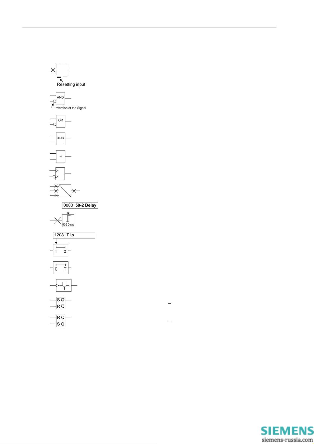
The following symbols are used in drawings:
Device-internal logical input signal
Device-internal logical output signal
Internal input signal of an analog quantity
External binary input signal with number (binary input,
input indication)
External binary input signal with number
(example of a value indication)
External binary output signal with number (device indication) used as
input signal
Example of a parameter switch designated FUNCTION with address
1234 and the possible settings ON and OFF
SIPROTEC, 7SD80, Manual
E50417-G1140-C474-A1, Release date 09.2011
7
Page 8
Preface
Besides these, graphical symbols are used according to IEC 60617-12 and IEC 60617-13 or symbols derived
from these standards. Some of the most frequently used are listed below:
Analog input variable
AND operation of input variables
OR operation of input variables
Exclusive OR (antivalence): output is active if only one of the inputs is
active
Coincidence: output is active if both inputs are active or inactive at the
same time
Dynamic input signals (edge-triggered) above with positive, below with
negative edge
Formation of one analog output signal from a number of analog input
signals
Threshold element with setting address and parameter names
Timer (pickup delay T adjustable) with setting address and parameter
names
Timer (dropout delay T not adjustable)
Edge-triggered time element with action time T
Static memory (SR flipflop) with setting input (S), resetting input (R),
output (Q) and inverted output (Q
), setting input dominant
Static memory (RS-flipflop) with resetting input (R) setting input (S),
output (Q) and inverted output (Q
), resetting input dominant
■
8
E50417-G1140-C474-A1, Release date 09.2011
SIPROTEC, 7SD80, Manual
Page 9

Contents
1 Introduction. . . . . . . . . . . . . . . . . . . . . . . . . . . . . . . . . . . . . . . . . . . . . . . . . . . . . . . . . . . . . . . . . . . . . . . . . . . . . .17
1.1 Overall Operation. . . . . . . . . . . . . . . . . . . . . . . . . . . . . . . . . . . . . . . . . . . . . . . . . . . . . . . . . . . . . . . . . .18
1.2 Application Scope . . . . . . . . . . . . . . . . . . . . . . . . . . . . . . . . . . . . . . . . . . . . . . . . . . . . . . . . . . . . . . . . .21
1.3 Characteristics. . . . . . . . . . . . . . . . . . . . . . . . . . . . . . . . . . . . . . . . . . . . . . . . . . . . . . . . . . . . . . . . . . . .23
2 Functions. . . . . . . . . . . . . . . . . . . . . . . . . . . . . . . . . . . . . . . . . . . . . . . . . . . . . . . . . . . . . . . . . . . . . . . . . . . . . . . .27
2.1 General . . . . . . . . . . . . . . . . . . . . . . . . . . . . . . . . . . . . . . . . . . . . . . . . . . . . . . . . . . . . . . . . . . . . . . . . .28
2.1.1 Functional Scope . . . . . . . . . . . . . . . . . . . . . . . . . . . . . . . . . . . . . . . . . . . . . . . . . . . . . . . . . . . . . . .28
2.1.1.1 Description . . . . . . . . . . . . . . . . . . . . . . . . . . . . . . . . . . . . . . . . . . . . . . . . . . . . . . . . . . . . . . . . .28
2.1.1.2 Setting Notes . . . . . . . . . . . . . . . . . . . . . . . . . . . . . . . . . . . . . . . . . . . . . . . . . . . . . . . . . . . . . . .29
2.1.1.3 Settings . . . . . . . . . . . . . . . . . . . . . . . . . . . . . . . . . . . . . . . . . . . . . . . . . . . . . . . . . . . . . . . . . . .31
2.1.2 Device, General Settings. . . . . . . . . . . . . . . . . . . . . . . . . . . . . . . . . . . . . . . . . . . . . . . . . . . . . . . . .33
2.1.2.1 Description . . . . . . . . . . . . . . . . . . . . . . . . . . . . . . . . . . . . . . . . . . . . . . . . . . . . . . . . . . . . . . . . .33
2.1.2.2 Setting Notes . . . . . . . . . . . . . . . . . . . . . . . . . . . . . . . . . . . . . . . . . . . . . . . . . . . . . . . . . . . . . . .34
2.1.2.3 Settings . . . . . . . . . . . . . . . . . . . . . . . . . . . . . . . . . . . . . . . . . . . . . . . . . . . . . . . . . . . . . . . . . . .34
2.1.2.4 Information List. . . . . . . . . . . . . . . . . . . . . . . . . . . . . . . . . . . . . . . . . . . . . . . . . . . . . . . . . . . . . .35
2.1.3 General Power System Data (Power System Data 1) . . . . . . . . . . . . . . . . . . . . . . . . . . . . . . . . . . .37
2.1.3.1 Setting Notes . . . . . . . . . . . . . . . . . . . . . . . . . . . . . . . . . . . . . . . . . . . . . . . . . . . . . . . . . . . . . . .37
2.1.3.2 Settings . . . . . . . . . . . . . . . . . . . . . . . . . . . . . . . . . . . . . . . . . . . . . . . . . . . . . . . . . . . . . . . . . . .40
2.1.4 Oscillographic Fault Records. . . . . . . . . . . . . . . . . . . . . . . . . . . . . . . . . . . . . . . . . . . . . . . . . . . . . .41
2.1.4.1 Description . . . . . . . . . . . . . . . . . . . . . . . . . . . . . . . . . . . . . . . . . . . . . . . . . . . . . . . . . . . . . . . . .41
2.1.4.2 Setting Notes . . . . . . . . . . . . . . . . . . . . . . . . . . . . . . . . . . . . . . . . . . . . . . . . . . . . . . . . . . . . . . .41
2.1.4.3 Settings . . . . . . . . . . . . . . . . . . . . . . . . . . . . . . . . . . . . . . . . . . . . . . . . . . . . . . . . . . . . . . . . . . . 4 2
2.1.4.4 Information List. . . . . . . . . . . . . . . . . . . . . . . . . . . . . . . . . . . . . . . . . . . . . . . . . . . . . . . . . . . . . .42
2.1.5 Change Group . . . . . . . . . . . . . . . . . . . . . . . . . . . . . . . . . . . . . . . . . . . . . . . . . . . . . . . . . . . . . . . . .43
2.1.5.1 Description . . . . . . . . . . . . . . . . . . . . . . . . . . . . . . . . . . . . . . . . . . . . . . . . . . . . . . . . . . . . . . . . .43
2.1.5.2 Setting Notes . . . . . . . . . . . . . . . . . . . . . . . . . . . . . . . . . . . . . . . . . . . . . . . . . . . . . . . . . . . . . . .43
2.1.5.3 Settings . . . . . . . . . . . . . . . . . . . . . . . . . . . . . . . . . . . . . . . . . . . . . . . . . . . . . . . . . . . . . . . . . . . 4 3
2.1.5.4 Information List. . . . . . . . . . . . . . . . . . . . . . . . . . . . . . . . . . . . . . . . . . . . . . . . . . . . . . . . . . . . . .44
2.1.6 General Protection Data (Power System Data 2) . . . . . . . . . . . . . . . . . . . . . . . . . . . . . . . . . . . . . .44
2.1.6.1 Setting Notes . . . . . . . . . . . . . . . . . . . . . . . . . . . . . . . . . . . . . . . . . . . . . . . . . . . . . . . . . . . . . . .44
2.1.6.2 Settings . . . . . . . . . . . . . . . . . . . . . . . . . . . . . . . . . . . . . . . . . . . . . . . . . . . . . . . . . . . . . . . . . . . 4 7
2.1.6.3 Information List. . . . . . . . . . . . . . . . . . . . . . . . . . . . . . . . . . . . . . . . . . . . . . . . . . . . . . . . . . . . . .48
2.1.7 EN100-Modul 1 . . . . . . . . . . . . . . . . . . . . . . . . . . . . . . . . . . . . . . . . . . . . . . . . . . . . . . . . . . . . . . . .49
2.1.7.1 Description . . . . . . . . . . . . . . . . . . . . . . . . . . . . . . . . . . . . . . . . . . . . . . . . . . . . . . . . . . . . . . . . .49
2.1.7.2 Information List. . . . . . . . . . . . . . . . . . . . . . . . . . . . . . . . . . . . . . . . . . . . . . . . . . . . . . . . . . . . . .49
2.1.8 Protection Interface . . . . . . . . . . . . . . . . . . . . . . . . . . . . . . . . . . . . . . . . . . . . . . . . . . . . . . . . . . . . .49
2.1.8.1 Description . . . . . . . . . . . . . . . . . . . . . . . . . . . . . . . . . . . . . . . . . . . . . . . . . . . . . . . . . . . . . . . . .49
2.1.8.2 Setting Notes . . . . . . . . . . . . . . . . . . . . . . . . . . . . . . . . . . . . . . . . . . . . . . . . . . . . . . . . . . . . . . .50
2.1.8.3 Settings . . . . . . . . . . . . . . . . . . . . . . . . . . . . . . . . . . . . . . . . . . . . . . . . . . . . . . . . . . . . . . . . . . . 5 1
2.1.8.4 Information List. . . . . . . . . . . . . . . . . . . . . . . . . . . . . . . . . . . . . . . . . . . . . . . . . . . . . . . . . . . . . .51
SIPROTEC, 7SD80, Manual
E50417-G1140-C474-A1, Release date 09.2011
9
Page 10

Contents
2.2 Phase Comparison Protection and Ground Differential Protection. . . . . . . . . . . . . . . . . . . . . . . . . . . .52
2.2.1 Differential Topol ogy . . . . . . . . . . . . . . . . . . . . . . . . . . . . . . . . . . . . . . . . . . . . . . . . . . . . . . . . . . . .52
2.2.1.1 Setting Notes. . . . . . . . . . . . . . . . . . . . . . . . . . . . . . . . . . . . . . . . . . . . . . . . . . . . . . . . . . . . . . .52
2.2.1.2 Settings . . . . . . . . . . . . . . . . . . . . . . . . . . . . . . . . . . . . . . . . . . . . . . . . . . . . . . . . . . . . . . . . . . .52
2.2.1.3 Information List . . . . . . . . . . . . . . . . . . . . . . . . . . . . . . . . . . . . . . . . . . . . . . . . . . . . . . . . . . . . .52
2.2.2 Phase Comparison Protection. . . . . . . . . . . . . . . . . . . . . . . . . . . . . . . . . . . . . . . . . . . . . . . . . . . . .53
2.2.2.1 Description. . . . . . . . . . . . . . . . . . . . . . . . . . . . . . . . . . . . . . . . . . . . . . . . . . . . . . . . . . . . . . . . .53
2.2.2.2 Setting Notes. . . . . . . . . . . . . . . . . . . . . . . . . . . . . . . . . . . . . . . . . . . . . . . . . . . . . . . . . . . . . . .57
2.2.3 Ground Current Differential Protection in Grounded Systems. . . . . . . . . . . . . . . . . . . . . . . . . . . . .59
2.2.3.1 Description. . . . . . . . . . . . . . . . . . . . . . . . . . . . . . . . . . . . . . . . . . . . . . . . . . . . . . . . . . . . . . . . .59
2.2.3.2 Setting Notes. . . . . . . . . . . . . . . . . . . . . . . . . . . . . . . . . . . . . . . . . . . . . . . . . . . . . . . . . . . . . . .62
2.2.4 Ground Fault Differential Protection in Resonant-grounded/Isolated Systems. . . . . . . . . . . . . . . .63
2.2.4.1 Description. . . . . . . . . . . . . . . . . . . . . . . . . . . . . . . . . . . . . . . . . . . . . . . . . . . . . . . . . . . . . . . . .63
2.2.4.2 Setting Notes. . . . . . . . . . . . . . . . . . . . . . . . . . . . . . . . . . . . . . . . . . . . . . . . . . . . . . . . . . . . . . .66
2.2.5 Differential Protection Pickup Logic and Tripping Logic . . . . . . . . . . . . . . . . . . . . . . . . . . . . . . . . . 67
2.2.5.1 Description. . . . . . . . . . . . . . . . . . . . . . . . . . . . . . . . . . . . . . . . . . . . . . . . . . . . . . . . . . . . . . . . .67
2.2.6 87 Differential Protection. . . . . . . . . . . . . . . . . . . . . . . . . . . . . . . . . . . . . . . . . . . . . . . . . . . . . . . . .68
2.2.6.1 Settings . . . . . . . . . . . . . . . . . . . . . . . . . . . . . . . . . . . . . . . . . . . . . . . . . . . . . . . . . . . . . . . . . . .69
2.2.6.2 Information List . . . . . . . . . . . . . . . . . . . . . . . . . . . . . . . . . . . . . . . . . . . . . . . . . . . . . . . . . . . . .70
2.2.7 Differential Protection Test and Commissioning . . . . . . . . . . . . . . . . . . . . . . . . . . . . . . . . . . . . . . .71
2.2.7.1 Differential Protection Test. . . . . . . . . . . . . . . . . . . . . . . . . . . . . . . . . . . . . . . . . . . . . . . . . . . . .71
2.2.7.2 Differential Protection Commissioning . . . . . . . . . . . . . . . . . . . . . . . . . . . . . . . . . . . . . . . . . . .73
2.3 Breaker Intertrip and Remote Tripping . . . . . . . . . . . . . . . . . . . . . . . . . . . . . . . . . . . . . . . . . . . . . . . . .75
2.3.1 Description . . . . . . . . . . . . . . . . . . . . . . . . . . . . . . . . . . . . . . . . . . . . . . . . . . . . . . . . . . . . . . . . . . .75
2.3.2 Setting Notes. . . . . . . . . . . . . . . . . . . . . . . . . . . . . . . . . . . . . . . . . . . . . . . . . . . . . . . . . . . . . . . . . .76
2.3.3 Settings . . . . . . . . . . . . . . . . . . . . . . . . . . . . . . . . . . . . . . . . . . . . . . . . . . . . . . . . . . . . . . . . . . . . . .77
2.3.4 Information List . . . . . . . . . . . . . . . . . . . . . . . . . . . . . . . . . . . . . . . . . . . . . . . . . . . . . . . . . . . . . . . .77
2.4 Backup Overcurrent . . . . . . . . . . . . . . . . . . . . . . . . . . . . . . . . . . . . . . . . . . . . . . . . . . . . . . . . . . . . . . .78
2.4.1 Operating Modes . . . . . . . . . . . . . . . . . . . . . . . . . . . . . . . . . . . . . . . . . . . . . . . . . . . . . . . . . . . . .78
2.4.2 Non-directional Overcurrent Protection. . . . . . . . . . . . . . . . . . . . . . . . . . . . . . . . . . . . . . . . . . . . . .78
2.4.3 Directional Overcurrent Protection . . . . . . . . . . . . . . . . . . . . . . . . . . . . . . . . . . . . . . . . . . . . . . . . .83
2.4.4 Setting Notes. . . . . . . . . . . . . . . . . . . . . . . . . . . . . . . . . . . . . . . . . . . . . . . . . . . . . . . . . . . . . . . . . .89
2.4.5 Settings . . . . . . . . . . . . . . . . . . . . . . . . . . . . . . . . . . . . . . . . . . . . . . . . . . . . . . . . . . . . . . . . . . . . . .93
2.4.6 Information List . . . . . . . . . . . . . . . . . . . . . . . . . . . . . . . . . . . . . . . . . . . . . . . . . . . . . . . . . . . . . . . .96
2.5 Inrush Restraint. . . . . . . . . . . . . . . . . . . . . . . . . . . . . . . . . . . . . . . . . . . . . . . . . . . . . . . . . . . . . . . . . . .98
2.5.1 Description . . . . . . . . . . . . . . . . . . . . . . . . . . . . . . . . . . . . . . . . . . . . . . . . . . . . . . . . . . . . . . . . . . .98
2.5.2 Setting Notes. . . . . . . . . . . . . . . . . . . . . . . . . . . . . . . . . . . . . . . . . . . . . . . . . . . . . . . . . . . . . . . . . .99
2.5.3 Settings . . . . . . . . . . . . . . . . . . . . . . . . . . . . . . . . . . . . . . . . . . . . . . . . . . . . . . . . . . . . . . . . . . . . .100
2.5.4 Information List . . . . . . . . . . . . . . . . . . . . . . . . . . . . . . . . . . . . . . . . . . . . . . . . . . . . . . . . . . . . . . .100
2.6 Circuit-Breaker Failure Protection 50BF . . . . . . . . . . . . . . . . . . . . . . . . . . . . . . . . . . . . . . . . . . . . . . .101
2.6.1 Description . . . . . . . . . . . . . . . . . . . . . . . . . . . . . . . . . . . . . . . . . . . . . . . . . . . . . . . . . . . . . . . . . .101
2.6.2 Setting Notes. . . . . . . . . . . . . . . . . . . . . . . . . . . . . . . . . . . . . . . . . . . . . . . . . . . . . . . . . . . . . . . . .108
2.6.3 Settings . . . . . . . . . . . . . . . . . . . . . . . . . . . . . . . . . . . . . . . . . . . . . . . . . . . . . . . . . . . . . . . . . . . . . 110
2.6.4 Information List . . . . . . . . . . . . . . . . . . . . . . . . . . . . . . . . . . . . . . . . . . . . . . . . . . . . . . . . . . . . . . . 111
10
E50417-G1140-C474-A1, Release date 09.2011
SIPROTEC, 7SD80, Manual
Page 11

Contents
2.7 Thermal Overload Protection 49 . . . . . . . . . . . . . . . . . . . . . . . . . . . . . . . . . . . . . . . . . . . . . . . . . . . . .112
2.7.1 Method of Operation . . . . . . . . . . . . . . . . . . . . . . . . . . . . . . . . . . . . . . . . . . . . . . . . . . . . . . . . . . .112
2.7.2 Setting Notes . . . . . . . . . . . . . . . . . . . . . . . . . . . . . . . . . . . . . . . . . . . . . . . . . . . . . . . . . . . . . . . . .113
2.7.3 Settings . . . . . . . . . . . . . . . . . . . . . . . . . . . . . . . . . . . . . . . . . . . . . . . . . . . . . . . . . . . . . . . . . . . . .115
2.7.4 Information List. . . . . . . . . . . . . . . . . . . . . . . . . . . . . . . . . . . . . . . . . . . . . . . . . . . . . . . . . . . . . . . .115
2.8 Undervoltage and Overvoltage Protection 27/59 (Optional) . . . . . . . . . . . . . . . . . . . . . . . . . . . . . . . .116
2.8.1 Overvoltage Protection (ANSI 59) . . . . . . . . . . . . . . . . . . . . . . . . . . . . . . . . . . . . . . . . . . . . . . . . .116
2.8.2 Undervoltage Protection (ANSI 27) . . . . . . . . . . . . . . . . . . . . . . . . . . . . . . . . . . . . . . . . . . . . . . . .121
2.8.3 Setting Notes . . . . . . . . . . . . . . . . . . . . . . . . . . . . . . . . . . . . . . . . . . . . . . . . . . . . . . . . . . . . . . . . .124
2.8.4 Settings . . . . . . . . . . . . . . . . . . . . . . . . . . . . . . . . . . . . . . . . . . . . . . . . . . . . . . . . . . . . . . . . . . . . .128
2.8.5 Information List. . . . . . . . . . . . . . . . . . . . . . . . . . . . . . . . . . . . . . . . . . . . . . . . . . . . . . . . . . . . . . . .130
2.9 Frequency Protection 81 (Optional). . . . . . . . . . . . . . . . . . . . . . . . . . . . . . . . . . . . . . . . . . . . . . . . . . .133
2.9.1 Description. . . . . . . . . . . . . . . . . . . . . . . . . . . . . . . . . . . . . . . . . . . . . . . . . . . . . . . . . . . . . . . . . . .133
2.9.2 Setting Notes . . . . . . . . . . . . . . . . . . . . . . . . . . . . . . . . . . . . . . . . . . . . . . . . . . . . . . . . . . . . . . . . .136
2.9.3 Settings . . . . . . . . . . . . . . . . . . . . . . . . . . . . . . . . . . . . . . . . . . . . . . . . . . . . . . . . . . . . . . . . . . . . .137
2.9.4 Information List. . . . . . . . . . . . . . . . . . . . . . . . . . . . . . . . . . . . . . . . . . . . . . . . . . . . . . . . . . . . . . . .138
2.10 Direct Local Trip. . . . . . . . . . . . . . . . . . . . . . . . . . . . . . . . . . . . . . . . . . . . . . . . . . . . . . . . . . . . . . . . . .139
2.10.1 Description. . . . . . . . . . . . . . . . . . . . . . . . . . . . . . . . . . . . . . . . . . . . . . . . . . . . . . . . . . . . . . . . . . .139
2.10.2 Setting Notes . . . . . . . . . . . . . . . . . . . . . . . . . . . . . . . . . . . . . . . . . . . . . . . . . . . . . . . . . . . . . . . . .140
2.10.3 Settings . . . . . . . . . . . . . . . . . . . . . . . . . . . . . . . . . . . . . . . . . . . . . . . . . . . . . . . . . . . . . . . . . . . . .140
2.10.4 Information List. . . . . . . . . . . . . . . . . . . . . . . . . . . . . . . . . . . . . . . . . . . . . . . . . . . . . . . . . . . . . . . .140
2.11 Automatic Reclosure Function 79 (Optional). . . . . . . . . . . . . . . . . . . . . . . . . . . . . . . . . . . . . . . . . . . .141
2.11.1 Description. . . . . . . . . . . . . . . . . . . . . . . . . . . . . . . . . . . . . . . . . . . . . . . . . . . . . . . . . . . . . . . . . . .141
2.11.2 Setting Notes . . . . . . . . . . . . . . . . . . . . . . . . . . . . . . . . . . . . . . . . . . . . . . . . . . . . . . . . . . . . . . . . .148
2.11.3 Settings . . . . . . . . . . . . . . . . . . . . . . . . . . . . . . . . . . . . . . . . . . . . . . . . . . . . . . . . . . . . . . . . . . . . .152
2.11.4 Information List. . . . . . . . . . . . . . . . . . . . . . . . . . . . . . . . . . . . . . . . . . . . . . . . . . . . . . . . . . . . . . . .154
2.12 Circuit-Breaker Test . . . . . . . . . . . . . . . . . . . . . . . . . . . . . . . . . . . . . . . . . . . . . . . . . . . . . . . . . . . . . . .155
2.12.1 CB Close Detection . . . . . . . . . . . . . . . . . . . . . . . . . . . . . . . . . . . . . . . . . . . . . . . . . . . . . . . . . . . .155
2.12.2 Circuit-Breaker Position Detection. . . . . . . . . . . . . . . . . . . . . . . . . . . . . . . . . . . . . . . . . . . . . . . . .158
2.12.3 Circuit-Breaker Test . . . . . . . . . . . . . . . . . . . . . . . . . . . . . . . . . . . . . . . . . . . . . . . . . . . . . . . . . . . .159
2.12.4 Information List. . . . . . . . . . . . . . . . . . . . . . . . . . . . . . . . . . . . . . . . . . . . . . . . . . . . . . . . . . . . . . . .160
2.13 Direct Remote Trip and Transmission of Binary Information. . . . . . . . . . . . . . . . . . . . . . . . . . . . . . . .161
2.13.1 Description. . . . . . . . . . . . . . . . . . . . . . . . . . . . . . . . . . . . . . . . . . . . . . . . . . . . . . . . . . . . . . . . . . .161
2.13.2 Information List. . . . . . . . . . . . . . . . . . . . . . . . . . . . . . . . . . . . . . . . . . . . . . . . . . . . . . . . . . . . . . . .162
SIPROTEC, 7SD80, Manual
E50417-G1140-C474-A1, Release date 09.2011
11
Page 12

Contents
2.14 Monitoring Functions. . . . . . . . . . . . . . . . . . . . . . . . . . . . . . . . . . . . . . . . . . . . . . . . . . . . . . . . . . . . . . 163
2.14.1 Measurement Supervision. . . . . . . . . . . . . . . . . . . . . . . . . . . . . . . . . . . . . . . . . . . . . . . . . . . . . . .163
2.14.1.1 Hardware Monitoring . . . . . . . . . . . . . . . . . . . . . . . . . . . . . . . . . . . . . . . . . . . . . . . . . . . . . . . .163
2.14.1.2 Software Monitoring . . . . . . . . . . . . . . . . . . . . . . . . . . . . . . . . . . . . . . . . . . . . . . . . . . . . . . . .165
2.14.1.3 External Transformer Circuits . . . . . . . . . . . . . . . . . . . . . . . . . . . . . . . . . . . . . . . . . . . . . . . . .165
2.14.1.4 Fault Responses . . . . . . . . . . . . . . . . . . . . . . . . . . . . . . . . . . . . . . . . . . . . . . . . . . . . . . . . . . . 174
2.14.1.5 Setting Notes. . . . . . . . . . . . . . . . . . . . . . . . . . . . . . . . . . . . . . . . . . . . . . . . . . . . . . . . . . . . . . 176
2.14.1.6 Settings . . . . . . . . . . . . . . . . . . . . . . . . . . . . . . . . . . . . . . . . . . . . . . . . . . . . . . . . . . . . . . . . . . 177
2.14.1.7 Information List . . . . . . . . . . . . . . . . . . . . . . . . . . . . . . . . . . . . . . . . . . . . . . . . . . . . . . . . . . . .178
2.14.2 74TC Trip Circuit Supervision . . . . . . . . . . . . . . . . . . . . . . . . . . . . . . . . . . . . . . . . . . . . . . . . . . . . 179
2.14.2.1 Method of Operation . . . . . . . . . . . . . . . . . . . . . . . . . . . . . . . . . . . . . . . . . . . . . . . . . . . . . . . .179
2.14.2.2 Setting Notes. . . . . . . . . . . . . . . . . . . . . . . . . . . . . . . . . . . . . . . . . . . . . . . . . . . . . . . . . . . . . . 182
2.14.2.3 Settings . . . . . . . . . . . . . . . . . . . . . . . . . . . . . . . . . . . . . . . . . . . . . . . . . . . . . . . . . . . . . . . . . . 182
2.14.2.4 Information List . . . . . . . . . . . . . . . . . . . . . . . . . . . . . . . . . . . . . . . . . . . . . . . . . . . . . . . . . . . .182
2.15 Flexible Protection Functions . . . . . . . . . . . . . . . . . . . . . . . . . . . . . . . . . . . . . . . . . . . . . . . . . . . . . . .183
2.15.1 Description . . . . . . . . . . . . . . . . . . . . . . . . . . . . . . . . . . . . . . . . . . . . . . . . . . . . . . . . . . . . . . . . . .183
2.15.2 Setting Notes. . . . . . . . . . . . . . . . . . . . . . . . . . . . . . . . . . . . . . . . . . . . . . . . . . . . . . . . . . . . . . . . .187
2.15.3 Settings . . . . . . . . . . . . . . . . . . . . . . . . . . . . . . . . . . . . . . . . . . . . . . . . . . . . . . . . . . . . . . . . . . . . .191
2.15.4 Information List . . . . . . . . . . . . . . . . . . . . . . . . . . . . . . . . . . . . . . . . . . . . . . . . . . . . . . . . . . . . . . .193
2.16 Function Control . . . . . . . . . . . . . . . . . . . . . . . . . . . . . . . . . . . . . . . . . . . . . . . . . . . . . . . . . . . . . . . . . 194
2.16.1 Pickup Logic for the Entire Device . . . . . . . . . . . . . . . . . . . . . . . . . . . . . . . . . . . . . . . . . . . . . . . .194
2.16.2 Overall Tripping Logic of the Device . . . . . . . . . . . . . . . . . . . . . . . . . . . . . . . . . . . . . . . . . . . . . . . 195
12
E50417-G1140-C474-A1, Release date 09.2011
SIPROTEC, 7SD80, Manual
Page 13

Contents
2.17 Additional Functions . . . . . . . . . . . . . . . . . . . . . . . . . . . . . . . . . . . . . . . . . . . . . . . . . . . . . . . . . . . . . .199
2.17.1 Indications Processing. . . . . . . . . . . . . . . . . . . . . . . . . . . . . . . . . . . . . . . . . . . . . . . . . . . . . . . . . .199
2.17.1.1 LEDs and Binary Outputs (Output Relays). . . . . . . . . . . . . . . . . . . . . . . . . . . . . . . . . . . . . . . .199
2.17.1.2 Information via Display Fi e ld or PC . . . . . . . . . . . . . . . . . . . . . . . . . . . . . . . . . . . . . . . . . . . . .200
2.17.1.3 Information to a Control Center . . . . . . . . . . . . . . . . . . . . . . . . . . . . . . . . . . . . . . . . . . . . . . . .201
2.17.2 Statistics. . . . . . . . . . . . . . . . . . . . . . . . . . . . . . . . . . . . . . . . . . . . . . . . . . . . . . . . . . . . . . . . . . . . .201
2.17.2.1 Description . . . . . . . . . . . . . . . . . . . . . . . . . . . . . . . . . . . . . . . . . . . . . . . . . . . . . . . . . . . . . . . .202
2.17.2.2 Information List. . . . . . . . . . . . . . . . . . . . . . . . . . . . . . . . . . . . . . . . . . . . . . . . . . . . . . . . . . . . .202
2.17.3 Measurement During Operation. . . . . . . . . . . . . . . . . . . . . . . . . . . . . . . . . . . . . . . . . . . . . . . . . . .203
2.17.3.1 Description . . . . . . . . . . . . . . . . . . . . . . . . . . . . . . . . . . . . . . . . . . . . . . . . . . . . . . . . . . . . . . . .203
2.17.3.2 Information List. . . . . . . . . . . . . . . . . . . . . . . . . . . . . . . . . . . . . . . . . . . . . . . . . . . . . . . . . . . . .205
2.17.4 Differential Protection Values. . . . . . . . . . . . . . . . . . . . . . . . . . . . . . . . . . . . . . . . . . . . . . . . . . . . .206
2.17.4.1 Measured Values of the Differential Protection . . . . . . . . . . . . . . . . . . . . . . . . . . . . . . . . . . . .206
2.17.4.2 Information List. . . . . . . . . . . . . . . . . . . . . . . . . . . . . . . . . . . . . . . . . . . . . . . . . . . . . . . . . . . . .206
2.17.5 Constellation Measured Values . . . . . . . . . . . . . . . . . . . . . . . . . . . . . . . . . . . . . . . . . . . . . . . . . . .206
2.17.5.1 Description . . . . . . . . . . . . . . . . . . . . . . . . . . . . . . . . . . . . . . . . . . . . . . . . . . . . . . . . . . . . . . . .206
2.17.6 Min/Max Measurement Setup . . . . . . . . . . . . . . . . . . . . . . . . . . . . . . . . . . . . . . . . . . . . . . . . . . . .207
2.17.6.1 Description . . . . . . . . . . . . . . . . . . . . . . . . . . . . . . . . . . . . . . . . . . . . . . . . . . . . . . . . . . . . . . . .207
2.17.6.2 Setting Notes . . . . . . . . . . . . . . . . . . . . . . . . . . . . . . . . . . . . . . . . . . . . . . . . . . . . . . . . . . . . . .207
2.17.6.3 Settings . . . . . . . . . . . . . . . . . . . . . . . . . . . . . . . . . . . . . . . . . . . . . . . . . . . . . . . . . . . . . . . . . .208
2.17.6.4 Information List. . . . . . . . . . . . . . . . . . . . . . . . . . . . . . . . . . . . . . . . . . . . . . . . . . . . . . . . . . . . .208
2.17.7 Demand Measurement Setup . . . . . . . . . . . . . . . . . . . . . . . . . . . . . . . . . . . . . . . . . . . . . . . . . . . .210
2.17.7.1 Description . . . . . . . . . . . . . . . . . . . . . . . . . . . . . . . . . . . . . . . . . . . . . . . . . . . . . . . . . . . . . . . .210
2.17.7.2 Setting Notes . . . . . . . . . . . . . . . . . . . . . . . . . . . . . . . . . . . . . . . . . . . . . . . . . . . . . . . . . . . . . .210
2.17.7.3 Settings . . . . . . . . . . . . . . . . . . . . . . . . . . . . . . . . . . . . . . . . . . . . . . . . . . . . . . . . . . . . . . . . . .210
2.17.7.4 Information List. . . . . . . . . . . . . . . . . . . . . . . . . . . . . . . . . . . . . . . . . . . . . . . . . . . . . . . . . . . . .211
2.17.8 Set Points (Measured Values) . . . . . . . . . . . . . . . . . . . . . . . . . . . . . . . . . . . . . . . . . . . . . . . . . . . .212
2.17.8.1 Setting Notes . . . . . . . . . . . . . . . . . . . . . . . . . . . . . . . . . . . . . . . . . . . . . . . . . . . . . . . . . . . . . .212
2.17.8.2 Information List. . . . . . . . . . . . . . . . . . . . . . . . . . . . . . . . . . . . . . . . . . . . . . . . . . . . . . . . . . . . .212
2.17.9 Energy . . . . . . . . . . . . . . . . . . . . . . . . . . . . . . . . . . . . . . . . . . . . . . . . . . . . . . . . . . . . . . . . . . . . . .213
2.17.9.1 Energy Metering. . . . . . . . . . . . . . . . . . . . . . . . . . . . . . . . . . . . . . . . . . . . . . . . . . . . . . . . . . . .213
2.17.9.2 Setting Notes . . . . . . . . . . . . . . . . . . . . . . . . . . . . . . . . . . . . . . . . . . . . . . . . . . . . . . . . . . . . . .213
2.17.9.3 Information List. . . . . . . . . . . . . . . . . . . . . . . . . . . . . . . . . . . . . . . . . . . . . . . . . . . . . . . . . . . . .213
2.18 Breaker Control . . . . . . . . . . . . . . . . . . . . . . . . . . . . . . . . . . . . . . . . . . . . . . . . . . . . . . . . . . . . . . . . . .214
2.18.1 Control Device . . . . . . . . . . . . . . . . . . . . . . . . . . . . . . . . . . . . . . . . . . . . . . . . . . . . . . . . . . . . . . . .214
2.18.1.1 Description . . . . . . . . . . . . . . . . . . . . . . . . . . . . . . . . . . . . . . . . . . . . . . . . . . . . . . . . . . . . . . . .214
2.18.1.2 Information List. . . . . . . . . . . . . . . . . . . . . . . . . . . . . . . . . . . . . . . . . . . . . . . . . . . . . . . . . . . . .215
2.18.2 Command Types . . . . . . . . . . . . . . . . . . . . . . . . . . . . . . . . . . . . . . . . . . . . . . . . . . . . . . . . . . . . . .216
2.18.2.1 Description . . . . . . . . . . . . . . . . . . . . . . . . . . . . . . . . . . . . . . . . . . . . . . . . . . . . . .
. . . . . . . . . .216
2.18.3 Command Sequence . . . . . . . . . . . . . . . . . . . . . . . . . . . . . . . . . . . . . . . . . . . . . . . . . . . . . . . . . . .217
2.18.3.1 Description . . . . . . . . . . . . . . . . . . . . . . . . . . . . . . . . . . . . . . . . . . . . . . . . . . . . . . . . . . . . . . . .217
2.18.4 Switchgear Interlocking Protection. . . . . . . . . . . . . . . . . . . . . . . . . . . . . . . . . . . . . . . . . . . . . . . . .218
2.18.4.1 Description . . . . . . . . . . . . . . . . . . . . . . . . . . . . . . . . . . . . . . . . . . . . . . . . . . . . . . . . . . . . . . . .218
2.18.5 Command Logging. . . . . . . . . . . . . . . . . . . . . . . . . . . . . . . . . . . . . . . . . . . . . . . . . . . . . . . . . . . . .228
2.18.5.1 Description . . . . . . . . . . . . . . . . . . . . . . . . . . . . . . . . . . . . . . . . . . . . . . . . . . . . . . . . . . . . . . . .228
2.19 Notes on Device Operation . . . . . . . . . . . . . . . . . . . . . . . . . . . . . . . . . . . . . . . . . . . . . . . . . . . . . . . . .229
2.19.1 Different operation . . . . . . . . . . . . . . . . . . . . . . . . . . . . . . . . . . . . . . . . . . . . . . . . . . . . . . . . . . . . .229
SIPROTEC, 7SD80, Manual
E50417-G1140-C474-A1, Release date 09.2011
13
Page 14

Contents
3 Mounting and Commissioning . . . . . . . . . . . . . . . . . . . . . . . . . . . . . . . . . . . . . . . . . . . . . . . . . . . . . . . . . . . . . 231
3.1 Mounting and Connections . . . . . . . . . . . . . . . . . . . . . . . . . . . . . . . . . . . . . . . . . . . . . . . . . . . . . . . . .232
3.1.1 Configuration Information . . . . . . . . . . . . . . . . . . . . . . . . . . . . . . . . . . . . . . . . . . . . . . . . . . . . . . .232
3.1.2 Hardware Modifications. . . . . . . . . . . . . . . . . . . . . . . . . . . . . . . . . . . . . . . . . . . . . . . . . . . . . . . . . 237
3.1.2.1 Disassembly . . . . . . . . . . . . . . . . . . . . . . . . . . . . . . . . . . . . . . . . . . . . . . . . . . . . . . . . . . . . . . 237
3.1.2.2 Connections of the Current Terminals . . . . . . . . . . . . . . . . . . . . . . . . . . . . . . . . . . . . . . . . . . .241
3.1.2.3 Connections of the Voltage Terminals . . . . . . . . . . . . . . . . . . . . . . . . . . . . . . . . . . . . . . . . . .243
3.1.2.4 Interface Modules . . . . . . . . . . . . . . . . . . . . . . . . . . . . . . . . . . . . . . . . . . . . . . . . . . . . . . . . . .244
3.1.2.5 Reassembly. . . . . . . . . . . . . . . . . . . . . . . . . . . . . . . . . . . . . . . . . . . . . . . . . . . . . . . . . . . . . . .247
3.1.3 Installation. . . . . . . . . . . . . . . . . . . . . . . . . . . . . . . . . . . . . . . . . . . . . . . . . . . . . . . . . . . . . . . . . . .248
3.1.3.1 General . . . . . . . . . . . . . . . . . . . . . . . . . . . . . . . . . . . . . . . . . . . . . . . . . . . . . . . . . . . . . . . . . . 248
3.1.3.2 Panel Flush Mounting . . . . . . . . . . . . . . . . . . . . . . . . . . . . . . . . . . . . . . . . . . . . . . . . . . . . . . . 249
3.1.3.3 Cubicle Mounting. . . . . . . . . . . . . . . . . . . . . . . . . . . . . . . . . . . . . . . . . . . . . . . . . . . . . . . . . . .250
3.1.3.4 Panel Surface Mounting . . . . . . . . . . . . . . . . . . . . . . . . . . . . . . . . . . . . . . . . . . . . . . . . . . . . .251
3.2 Checking Connections . . . . . . . . . . . . . . . . . . . . . . . . . . . . . . . . . . . . . . . . . . . . . . . . . . . . . . . . . . . .252
3.2.1 Checking the Data Connections of the Interfaces. . . . . . . . . . . . . . . . . . . . . . . . . . . . . . . . . . . . .252
3.2.2 Checking the Protection Data Communication . . . . . . . . . . . . . . . . . . . . . . . . . . . . . . . . . . . . . . .255
3.2.3 Checking the System Connections . . . . . . . . . . . . . . . . . . . . . . . . . . . . . . . . . . . . . . . . . . . . . . . . 256
3.3 Commissioning . . . . . . . . . . . . . . . . . . . . . . . . . . . . . . . . . . . . . . . . . . . . . . . . . . . . . . . . . . . . . . . . . .258
3.3.1 Test Mode and Transmission Block. . . . . . . . . . . . . . . . . . . . . . . . . . . . . . . . . . . . . . . . . . . . . . . .259
3.3.2 Checking Time Synchronization . . . . . . . . . . . . . . . . . . . . . . . . . . . . . . . . . . . . . . . . . . . . . . . . . .259
3.3.3 Testing the System Interface (at Port B) . . . . . . . . . . . . . . . . . . . . . . . . . . . . . . . . . . . . . . . . . . . .260
3.3.4 Configuring Communication Modules . . . . . . . . . . . . . . . . . . . . . . . . . . . . . . . . . . . . . . . . . . . . . .262
3.3.5 Checking the Status of Binary Inputs and Outputs . . . . . . . . . . . . . . . . . . . . . . . . . . . . . . . . . . . . 265
3.3.6 Checking the Protection Data Communication . . . . . . . . . . . . . . . . . . . . . . . . . . . . . . . . . . . . . . .268
3.3.7 Tests for Circuit-Breaker Failure Protection. . . . . . . . . . . . . . . . . . . . . . . . . . . . . . . . . . . . . . . . . . 270
3.3.8 Checking the Instrument Transformer Connections of One Line End. . . . . . . . . . . . . . . . . . . . . .272
3.3.9 Checking the Instrument Transformer Connections of Two Line Ends . . . . . . . . . . . . . . . . . . . . . 277
3.3.10 Checking the Pilot Protection for Internal and External Remote Tripping . . . . . . . . . . . . . . . . . . .277
3.3.11 Testing User-defined Functions. . . . . . . . . . . . . . . . . . . . . . . . . . . . . . . . . . . . . . . . . . . . . . . . . . .277
3.3.12 Trip and Close Test with the Circuit Breaker . . . . . . . . . . . . . . . . . . . . . . . . . . . . . . . . . . . . . . . . .278
3.3.13 Switching Check for the Configured Equipment . . . . . . . . . . . . . . . . . . . . . . . . . . . . . . . . . . . . . .278
3.3.14 Triggering Oscillographic Recording for Test . . . . . . . . . . . . . . . . . . . . . . . . . . . . . . . . . . . . . . . 279
3.4 Final Preparation of the Device. . . . . . . . . . . . . . . . . . . . . . . . . . . . . . . . . . . . . . . . . . . . . . . . . . . . . .280
4 Technical Data . . . . . . . . . . . . . . . . . . . . . . . . . . . . . . . . . . . . . . . . . . . . . . . . . . . . . . . . . . . . . . . . . . . . . . . . . .281
4.1 General Device Data. . . . . . . . . . . . . . . . . . . . . . . . . . . . . . . . . . . . . . . . . . . . . . . . . . . . . . . . . . . . . . 282
4.1.1 Analog Inputs . . . . . . . . . . . . . . . . . . . . . . . . . . . . . . . . . . . . . . . . . . . . . . . . . . . . . . . . . . . . 282
4.1.2 Auxiliary Voltage . . . . . . . . . . . . . . . . . . . . . . . . . . . . . . . . . . . . . . . . . . . . . . . . . . . . . . 283
4.1.3 Binary Inputs and Outputs . . . . . . . . . . . . . . . . . . . . . . . . . . . . . . . . . . . . . . . . . . . . . . .2 84
4.1.4 Communication Interfaces . . . . . . . . . . . . . . . . . . . . . . . . . . . . . . . . . . . . . . . . . . . . . . . . . . . . .285
4.1.5 Electrical Tests . . . . . . . . . . . . . . . . . . . . . . . . . . . . . . . . . . . . . . . . . . . . . . . . . . . . . . . . . . . .288
4.1.6 Mechanical Stress Tests . . . . . . . . . . . . . . . . . . . . . . . . . . . . . . . . . . . . . . . . . . . . . . . . . . .290
4.1.7 Climatic Stress Tests . . . . . . . . . . . . . . . . . . . . . . . . . . . . . . . . . . . . . . . . . . . . . . . . . . . . . . . 290
4.1.8 Service Conditions . . . . . . . . . . . . . . . . . . . . . . . . . . . . . . . . . . . . . . . . . . . . . . . . . . . . . . . .291
4.1.9 Design . . . . . . . . . . . . . . . . . . . . . . . . . . . . . . . . . . . . . . . . . . . . . . . . . . . . . . . . . . . . . . . . .291
4.1.10 UL certification conditions . . . . . . . . . . . . . . . . . . . . . . . . . . . . . . . . . . . . . . . . . . . . . . . . . . . . . . .292
14
E50417-G1140-C474-A1, Release date 09.2011
SIPROTEC, 7SD80, Manual
Page 15

Contents
4.2 Protection interfaces and Connections . . . . . . . . . . . . . . . . . . . . . . . . . . . . . . . . . . . . . . . . . . . . . . . .293
4.3 87 Differential Protection Phase Comparison Protection. . . . . . . . . . . . . . . . . . . . . . . . . . . . . . . . . . .296
4.4 Ground Fault Differential Protection in Grounded Systems . . . . . . . . . . . . . . . . . . . . . . . . . . . . . . . .299
4.5 Ground Fault Differential Protection in Resonant-grounded / Isolated Systems . . . . . . . . . . . . . . . . .300
4.6 Breaker Intertrip and Remote Tripping- Direct Local Trip . . . . . . . . . . . . . . . . . . . . . . . . . . . . . . . . . .301
4.7 Time Overcurrent Protection . . . . . . . . . . . . . . . . . . . . . . . . . . . . . . . . . . . . . . . . . . . . . . . . . . . . . . . .302
4.8 Inrush Current Restraint Breaker Intertrip and Remote Tripping. . . . . . . . . . . . . . . . . . . . . . . . . . . . .309
4.9 Circuit-Breaker Failure Protection (Optional). . . . . . . . . . . . . . . . . . . . . . . . . . . . . . . . . . . . . . . . . . . .310
4.10 Thermal Overload Protection 49 . . . . . . . . . . . . . . . . . . . . . . . . . . . . . . . . . . . . . . . . . . . . . . . . . . . . .311
4.11 Voltage Protection (Optional) . . . . . . . . . . . . . . . . . . . . . . . . . . . . . . . . . . . . . . . . . . . . . . . . . . . . . . .313
4.12 Frequency Protection (Optional) . . . . . . . . . . . . . . . . . . . . . . . . . . . . . . . . . . . . . . . . . . . . . . . . . . . . .316
4.13 Automatic Reclosing (Optional) . . . . . . . . . . . . . . . . . . . . . . . . . . . . . . . . . . . . . . . . . . . . . . . . . . . . . .317
4.14 Transmission of Binary Information and Commands. . . . . . . . . . . . . . . . . . . . . . . . . . . . . . . . . . . . . .318
4.15 Monitoring Functions . . . . . . . . . . . . . . . . . . . . . . . . . . . . . . . . . . . . . . . . . . . . . . . . . . . . . . . . . . . . . .319
4.16 Flexible Protection Functions . . . . . . . . . . . . . . . . . . . . . . . . . . . . . . . . . . . . . . . . . . . . . . . . . .321
4.17 User-defined Functions (CFC). . . . . . . . . . . . . . . . . . . . . . . . . . . . . . . . . . . . . . . . . . . . . . . . . . . . . . .324
4.18 Additional Functions . . . . . . . . . . . . . . . . . . . . . . . . . . . . . . . . . . . . . . . . . . . . . . . . . . . . . . . . . . . . . .328
4.19 Dimensions . . . . . . . . . . . . . . . . . . . . . . . . . . . . . . . . . . . . . . . . . . . . . . . . . . . . . . . . . . . . . . . . . . . . .330
4.19.1 Panel Flush Mounting and Cabinet Flush Mounting (H ousing Size 1/6) . . . . . . . . . . . . . . . . . . . .330
4.19.2 Panel Surface Mounting (Housing Size 1/6) . . . . . . . . . . . . . . . . . . . . . . . . . . . . . . . . . . . . . . . .331
4.19.3 Bottom View. . . . . . . . . . . . . . . . . . . . . . . . . . . . . . . . . . . . . . . . . . . . . . . . . . . . . . . . . . . . . . . . . .332
A Appendix . . . . . . . . . . . . . . . . . . . . . . . . . . . . . . . . . . . . . . . . . . . . . . . . . . . . . . . . . . . . . . . . . . . . . . . . . . . . . . .333
A.1 Ordering Information and Accessories . . . . . . . . . . . . . . . . . . . . . . . . . . . . . . . . . . . . . . . . . . . . . . . .334
A.1.1 Ordering Information . . . . . . . . . . . . . . . . . . . . . . . . . . . . . . . . . . . . . . . . . . . . . . . . . . . . . . . . . . . 334
A.1.1.1 7SD80 V4.6 . . . . . . . . . . . . . . . . . . . . . . . . . . . . . . . . . . . . . . . . . . . . . . . . . . . . . . . . . . . . .334
A.1.2 Accessories . . . . . . . . . . . . . . . . . . . . . . . . . . . . . . . . . . . . . . . . . . . . . . . . . . . . . . . . . . . . . . . . . .337
A.2 Terminal Assignments . . . . . . . . . . . . . . . . . . . . . . . . . . . . . . . . . . . . . . . . . . . . . . . . . . . . . . . . . . . . .339
A.2.1 7SD80 — Housing for Panel Flush Mounting and Cabinet Flush Mounting and
for Panel Surface Mounting . . . . . . . . . . . . . . . . . . . . . . . . . . . . . . . . . . . . . . . . . . . . . . . . . . . . .339
A.3 Connection Examples . . . . . . . . . . . . . . . . . . . . . . . . . . . . . . . . . . . . . . . . . . . . . . . . . . . . . . . . . . . . .345
A.4 Current Transformer Requirements. . . . . . . . . . . . . . . . . . . . . . . . . . . . . . . . . . . . . . . . . . . . . . . . . . .348
A.4.1 Current Transformer Ratio: . . . . . . . . . . . . . . . . . . . . . . . . . . . . . . . . . . . . . . . . . . . . . . . . . . . . . .348
A.4.2 Overcurrent Factors . . . . . . . . . . . . . . . . . . . . . . . . . . . . . . . . . . . . . . . . . . . . . . . . . . . . . . . . . . .348
A.4.3 Class Conversion. . . . . . . . . . . . . . . . . . . . . . . . . . . . . . . . . . . . . . . . . . . . . . . . . . . . . . . . . . . . . .349
A.4.4 Core Balance Current Transformer . . . . . . . . . . . . . . . . . . . . . . . . . . . . . . . . . . . . . . . . . . . . . . . .349
General. . . . . . . . . . . . . . . . . . . . . . . . . . . . . . . . . . . . . . . . . . . . . . . . . . . . . . . . . . . . . . . . . . .349
Requirements. . . . . . . . . . . . . . . . . . . . . . . . . . . . . . . . . . . . . . . . . . . . . . . . . . . . . . . . . . . . . .349
Class Accuracy. . . . . . . . . . . . . . . . . . . . . . . . . . . . . . . . . . . . . . . . . . . . . . . . . . . . . . . . . . . . .350
SIPROTEC, 7SD80, Manual
E50417-G1140-C474-A1, Release date 09.2011
15
Page 16

Contents
A.5 Default Settings. . . . . . . . . . . . . . . . . . . . . . . . . . . . . . . . . . . . . . . . . . . . . . . . . . . . . . . . . . . . . . . . . .351
A.5.1 LEDs . . . . . . . . . . . . . . . . . . . . . . . . . . . . . . . . . . . . . . . . . . . . . . . . . . . . . . . . . . . . . . . . . . . . . . .351
A.5.2 Binary Input . . . . . . . . . . . . . . . . . . . . . . . . . . . . . . . . . . . . . . . . . . . . . . . . . . . . . . . . . . . . . . . . . .351
A.5.3 Binary Output . . . . . . . . . . . . . . . . . . . . . . . . . . . . . . . . . . . . . . . . . . . . . . . . . . . . . . . . . . . . . . . .352
A.5.4 Function Keys . . . . . . . . . . . . . . . . . . . . . . . . . . . . . . . . . . . . . . . . . . . . . . . . . . . . . . . . . . . . . . . .352
A.5.5 Default Display . . . . . . . . . . . . . . . . . . . . . . . . . . . . . . . . . . . . . . . . . . . . . . . . . . . . . . . . . . . . . . . 353
A.5.6 Pre-defined CFC Charts . . . . . . . . . . . . . . . . . . . . . . . . . . . . . . . . . . . . . . . . . . . . . . . . . . . . . . . . 356
A.6 Protocol-dependent Functions . . . . . . . . . . . . . . . . . . . . . . . . . . . . . . . . . . . . . . . . . . . . . . . . . . . . . . 357
A.7 Functional Scope . . . . . . . . . . . . . . . . . . . . . . . . . . . . . . . . . . . . . . . . . . . . . . . . . . . . . . . . . . . . . . . .358
A.8 Settings. . . . . . . . . . . . . . . . . . . . . . . . . . . . . . . . . . . . . . . . . . . . . . . . . . . . . . . . . . . . . . . . . . . . . . . .360
A.9 Information List . . . . . . . . . . . . . . . . . . . . . . . . . . . . . . . . . . . . . . . . . . . . . . . . . . . . . . . . . . . . . . . . . .371
A.10 Group Alarms . . . . . . . . . . . . . . . . . . . . . . . . . . . . . . . . . . . . . . . . . . . . . . . . . . . . . . . . . . . . . . . . . . . 393
A.11 Measured Values . . . . . . . . . . . . . . . . . . . . . . . . . . . . . . . . . . . . . . . . . . . . . . . . . . . . . . . . . . . . . . . .394
Literature. . . . . . . . . . . . . . . . . . . . . . . . . . . . . . . . . . . . . . . . . . . . . . . . . . . . . . . . . . . . . . . . . . . . . . . . . . . . . . .399
Glossary . . . . . . . . . . . . . . . . . . . . . . . . . . . . . . . . . . . . . . . . . . . . . . . . . . . . . . . . . . . . . . . . . . . . . . . . . . . . . . .401
Index . . . . . . . . . . . . . . . . . . . . . . . . . . . . . . . . . . . . . . . . . . . . . . . . . . . . . . . . . . . . . . . . . . . . . . . . . . . . . . . . . . 413
16
E50417-G1140-C474-A1, Release date 09.2011
SIPROTEC, 7SD80, Manual
Page 17

Introduction 1
This chapter introduces the SIPROTEC 4 7SD80 and gives an overview of the device's application, properties
and functions.
1.1 Overall Operation 18
1.2 Application Scope 21
1.3 Characteristics 23
SIPROTEC, 7SD80, Manual
E50417-G1140-C474-A1, Release date 09.2011
17
Page 18
Introduction
1.1 Overall Operation
1.1 Overall Operation
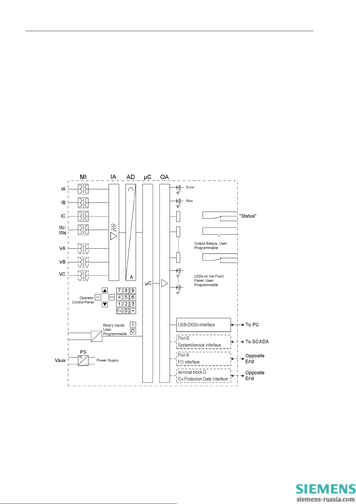
The digital SIPROTEC 7SD80 overcurrent protection is equipped with a powerful microprocessor. It allows all
tasks to be processed digitally, from the acquisition of measured quantities to sending commands to circuit
breakers. Figure 1-1 shows the basic structure of the 7SD80 device.
Analog Inputs
The measuring inputs (MI) convert the currents and voltages coming from the instrument transformers and
adapt them to the level appropriate for the internal processing of the device. The device provides 4 current
transformers and - depending on the model - additionally 3 voltage transformers. Three current inputs serve for
the input of the phase currents, another current input (I
I
(current transformer starpoint) or for a separate ground current transformer (for sensitive ground fault detec-
N
tion I
and directional determination of ground faults) - depending on the model.
Ns
) may be used for measuring the ground fault current
N
18
Figure 1-1 Hardware structure of the 7SD80 differential protection
E50417-G1140-C474-A1, Release date 09.2011
SIPROTEC, 7SD80, Manual
Page 19

There is one voltage input available for each phase-to-ground voltage. The differential protection does not need
measuring voltages due to its functional principle. Directional overcurrent protection, however, requires the
phase-to-ground voltage V
displaying voltages and power values and also measuring the line voltage for automatic reclosing. The analog
quantities are forwarded to the input amplifier group (IA).
The input amplifier group IA provides high-resistance termination for the analog input quantities. It consists of
filters that are optimized for measured value processing with regard to bandwidth and processing speed.
The analog-to-digital (AD) element consists of an analog-to-digital (A/D) converter and memory components
for data transmission to the microcomputer system.
Microcomputer System
Apart from processing the measured values, the microcomputer system µC also executes the actual protection
and control functions. They especially consist of:
• Filtering and preparation of the measured quantities
• Continuous monitoring of the measured quantities
• Monitoring of the pickup conditions for the individual protection functions
• Interrogation of limit values and time sequences
• Control of signals for the logic functions
• Decision on trip and close commands
• Recording of messages, fault data and fault values for analysis
• Administration of the operating system and its functions, e.g. data storage, realtime clock, communication,
interfaces, etc.
• Formation of the local differential protection values (phasor analysis and charge current computation) and
creation of the transmission protocol
• Decoding the received transmission protocol, synchronization of differential protection values and totaling
the differential currents and charge currents
• Monitoring the communication with the device of the remote en d
Introduction
1.1 Overall Operation
, VB and VC to be connected. Additionally, voltages can be connected that allow
A
The information is provided via output amplifier OA.
Binary Inputs and Outputs
Binary inputs and outputs to and from the computer system are relayed via the input/output modules. The computer system obtains information from the system (e.g. remote resetting) or from other devices (e.g. blocking
commands). Outputs are, in particular, commands to the switchgear units and annunciations for remote signaling of important events and statuses.
SIPROTEC, 7SD80, Manual
E50417-G1140-C474-A1, Release date 09.2011
19
Page 20

Introduction
1.1 Overall Operation
Front Elements
Information such as messages related to events, states, measured values and the functional status of the
device are visualized by light-emitting diodes (LEDs) and a display screen (LCD) on the front panel.
Integrated control and numeric keys in conjunction with the LCD enable communication with the remote device.
These elements enable the user to retrieve all device information such as configuration and setting parameters,
operational indications and fault indications or measured values and to edit setting parameters.
In addition, control of circuit breakers and other equipment is possible from the front panel of the device.
Interfaces
Communication with a PC can be implemented via the USB DIGSI interface using the DIGSI software allowing
the user to conveniently handle all device functions.
Port A can be used as protection interface to communicate with another 7SD80 device via an optical fiber
cable.
If you are using a copper link to create a connection to the other 7SD80 device, use the voltage terminals D1
and D2 as protection interface.
The protection data interfaces are used to transfer the data of the measured quantities from each end of the
protected zone to the opposite end. Further information such as closing of the local circuit breaker or other externally injected trip commands can be transmitted to the opposite end via the protection interface.
In addition to the device communication via DIGSI, port B can also be used to transmit all device data to a
central evaluator or a control center. This interface may be provided with various protocols and physical transmission schemes to suit the particular application.
Power Supply
The functional units described are supplied by a power supply (PS) with the adequate power in the different
voltage levels. Transient voltage dips may occur if the auxiliary voltage supply system becomes short-circuited.
Usually, they are bridged by a capacitor storage (see also the Section 4, Technical Data).
A buffer battery is located behind the lower front cover.
20
E50417-G1140-C474-A1, Release date 09.2011
SIPROTEC, 7SD80, Manual
Page 21

1.2 Application Scope
The digital Line Differential Protection SIPROTEC 4 7SD80 is a selective short-circuit protection for overhead
lines and cables with single- and multi-ended infeeds in radial, ring or any type of meshed systems of any transmission level. The measured data are compared separately for each phase.
A major advantage of the differential protection principle is the instantaneous tripping in the event of a short
circuit at any point within the entire protected zone. The current transformers limit the protected zone at the
ends towards the remaining system. This rigid delimitation is the reason why the differential protection scheme
shows such an ideal selectivity.
The differential protection system requires a 7SD80 device as well as a set of current transformers at either
end of the protected zone. Voltage transformers are not required for the differential protection functions in the
7SD80; they are, however, available to record and display measured values (voltages, power, power factor) or
when using a directional overcurrent protection element.
The devices located at the ends of the protected zone exchange measuring information via protection interfaces using communication links (usually optical fiber or copper cables).
Since fault-free data transmission is the prerequisite for the proper operation of the protection, it is continuously
monitored internally.
Introduction
1.2 Application Scope
Protection Functions
The device's basic function is to detect short-circuits or ground faults in the protected zone – even weak-current
or high-resistance short-circuits. Even complex multiphase faults are detected correctly, as the measured
values are evaluated separately for each phase. The protection is restraint against inrush currents of power
transformers. When switching a line onto a fault, it is possible to send an instantaneous trip signal. The 7SD80
line differential protection includes the differential protection functions of phase comparison protection and
ground fault differential protection. Both differential protection functions operate independently of each other.
In the event of a communication failure, the devices can automatically switch to emergency operation using an
integrated overcurrent protection until communication is restored. The overcurrent protection comprises two
definite time-overcurrent protection elements and one inverse time-overcurrent protection element. Both elements operate directional or non-directional. Additionally, the device features a third definite time-overcurrent
protection element that always operates non-directionally.
For inverse time overcurrent protection, several characteristic curves of different standards are available.
Alternatively, the time overcurrent protection can be used as a backup time overcurrent protection, i.e. it oper-
ates independent of and parallel to the differential protection at either end.
The communication link can be used for transmitting further information. Besides measured values, it is possi-
ble to transmit binary information.
All protection functions in the 7SD80 always trip 3-pole. They can work together with an integrated automatic
reclose function (optional). The automatic reclose functions enables 3-pole automatic reclosing with two
reclose attempts.
The thermal overload protection protects cables and power transformers from inadmissible heating due to overload.
Additionally, a two-element overvoltage and undervoltage protection and a four-element frequency protection
can be used. A circuit-breaker failure protection monitors the response of the circuit breaker following a trip
command.
SIPROTEC, 7SD80, Manual
E50417-G1140-C474-A1, Release date 09.2011
21
Page 22

Introduction
1.2 Application Scope
Control Functions
The device provides a control function which can be accomplished for activating and deactivating switchgear
via operator buttons, port B, binary inputs and - using a PC and the DIGSI software - via the front interface.
The switch positions are fed back to the device via auxiliary contacts of the circuit breakers and binary inputs.
The current switch positions can be read out at the device and used for plausibility monitoring and interlockings.
The number of the devices to be switched is limited by the binary inputs and outputs available in the device or
the binary inputs and outputs allocated for the switch position feedbacks. Depending on the equipment, one
binary input (single point indication) or two binary inputs (double point indication) can be used. The release to
switch can be restricted by appropriate settings for the switching authority (remote or local), and by the operating mode (interlocked/non-interlocked, with or without password validation). Interlocking conditions for
switching (e.g. switchgear interlocking) can be defined with the help of integrated user-configurable logic functions.
Messages and Measured Values; Recording of Event and Fault Data
The operational indications provide information about conditions in the power system and the device. Measurement quantities and values that are calculated can be displayed locally and communicated via the serial interfaces.
Device messages can be assigned to a number of LEDs on the front cover (allocatable), can be externally processed via output contacts (allocatable), linked with user-definable logic functions and/or issued via serial interfaces.
During a fault (system fault) important events and changes in conditions are saved in fault protocols (Event Log
or Trip Log). Instantaneous fault values are also saved in the device and may be analyzed subsequently.
Communication
The following interfaces are available for communication with external operating, control and memory systems.
The USB DIGSI interface on the front cover serves for local communication with a PC. With the SIPROTEC 4
operating software DIGSI, all operation and evaluation tasks can be executed using this operator interface, for
instance specifying and editing configuration parameters and settings, configuring user-specific logic functions,
retrieving operational messages and measured values, inquiring device conditions and measured values,
issuing control commands.
Port A is located on the bottom side of the device. This protection data interface connects the device to its
partner device at the remote end of the protected object.
Alternatively, you can implement the communication link using the voltage terminals D-1 and D-2.
Port B serves for central communication between the device and a control center. It can be operated via data
lines or optical fiber cables. For the data transfer, standardized protocols according IEC 60870-5-103 are available. The integration of the devices into the SINAUT LSA and SICAM automation systems can also be implemented with this profile.
Alternatively, there are additional connection options available in connection with PROFIBUS DP and the
DNP3.0 and MODBUS protocols. If an EN100 module is available, it is also possible to use the IEC61850 protocol.
You can also use port B to connect a time synchronization device such as DCF77 or IRIG-B.
22
E50417-G1140-C474-A1, Release date 09.2011
SIPROTEC, 7SD80, Manual
Page 23

1.3 Characteristics
General Properties
• Powerful 32-bit microprocessor system
• Complete digital processing of measured values and control, from the sampling of the analog input values,
the processing and organization of the communication between devices up to the closing and tripping commands to the circuit breakers.
• Total galvani c and fail-safe separation of the internal processing circuits from the measuring, control and
supply circuits of the system via measuring transformers, binary input and output modules and DC or AC
converters
• Suited for lines with two ends, even with transformers in the protected zone
• Easy device operation using the integrated operator panel or from a connected personal computer running
DIGSI
• Storage of fault indications as well as instantaneous values for fault recording
• Digital protection data transmission; communication of the device through optical fiber cables
• Communication is possible via a single copper wire pair (typically 8 km (4.97 miles), max. 20 km
(12.43 miles), depending on the used cable type, see Section 4, Technical Data).
Introduction
1.3 Characteristics
• Permanent supervision of the protection data transmission for disturbance, failure or transfer time variations
Phase Comparison Protection
• Differential protection for two ends with digital protection data transmission
• Protection for all types of short-circuits in systems with any starpoint conditioning
• Reliable distinction between load and short-circuit conditions using adaptive measureme nt methods, also
for high-resistance faults with small fault currents
• High sensitivity in light load operation, highest stability against load steps and power fluctuations
• Due to phase segregated measurement, the pickup sensitivity is independent of the fault type
• Suited for feeder transformers in the protected zone
• Detection of high-resistance, weak-current faults due to high sensitivity of the protection functions
• Fast tripping also on weak or zero infeed ends (breaker intertrip)
• No frequency dependency
Ground Fault Differential Protection for Grounded Systems
• Short command time
• High sensitivity for short circuits to ground
• High stability against external ground faults by stabilizing the through-flowing ground current
Ground Fault Differential Protection for Isolated / Grounded Systems
• Short command time
• High sensitivity for short circuits to ground
• High stability against external short-circuits to ground using the magnitude and phase relationship of the
ground current flowing through for stabilization
SIPROTEC, 7SD80, Manual
E50417-G1140-C474-A1, Release date 09.2011
23
Page 24

Introduction
1.3 Characteristics
External Direct and Remote T ripping
• Tripping of the local end by an external device via binary input
• Tripping of the opposite end by local protection functions or by an external device via binary input
Time Overcurrent Protection
• Optionally selectable as emergency function during protection data communication failure or as backup
function or both
• A maximum of 3 definite time elements and one inverse time element, each for phase currents and ground
current
• A maximum of 2 directional definite time elements and one directional inverse time element, each for phase
currents and ground current
• For inverse time overcurrent protection, selection from various characteristics of different standards possible
• Blocking options e.g. for reverse interlocking with any element
• Instantaneous tripping when closing onto a short circuit possible with any element
Inrush Current Restraint
• Insensitive to inrush currents, even in the case of feeder transformers in the protected zone, and against
higher-frequency transients
• High stability also for different current transformer saturation
Circuit-Breaker Failure Protection
• With independent current elements for the monitoring of the current flow through each pole of the circuit
breaker
• Separate pickup thresholds for phase and ground currents
• Monitoring time element for tripping
• Initiation by the trip command of each integrated protection function
• Initiation by external trip functions possible
• Single-element or two-element
• No dropout and seal-in times
Thermal Overload Protection
• Thermal replica of the current heat losses of the protected object
• RMS measurement for all three phase currents
• Adjustable thermal and current-dependent warning elements
24
E50417-G1140-C474-A1, Release date 09.2011
SIPROTEC, 7SD80, Manual
Page 25

Vo ltage Protection
• Overvoltage and undervoltage detection with different elements
• Two overvoltage elements for the phase-to-ground voltages
• Two overvoltage elements for the phase-to-phase voltages
• Two overvoltage elements for the positive sequence voltage
• Two overvoltage elements for the negative sequence system of the voltages
• Two overvoltage elements for the zero system of the voltages or for any other single-phase voltage
• Adjustable dropout conditions
• Two undervoltage elements for the phase-to-ground voltages
• Two undervoltage elements for the phase-to-phase voltages
• Two undervoltage elements for the positive sequence system of the voltages
• Adjustable current criterion for undervoltage protection functions
Frequency Protection 81 (Optional)
• Monitoring of falling below (f<) and/or exceeding (f>) with 4 frequency limits and time delays that are independently adjustable
Introduction
1.3 Characteristics
• Particularly insensitive to harmonics and abrupt phase angle changes
• Wide frequency range (approx. 25 Hz to 70 Hz)
Automatic Reclose Function (Optional)
• For reclosing after 3-pole open condition
• Two recl o si n g attempts
• With separate action times for each reclosing attempt, optionally without action times
• With separate dead times
• Optionally controlled by protection element pickup with separate dead times after 1-pole, 2-pole or 3-pole
pickup
Monitoring Functions
• Reliability of the device is greatly increased because of self-monitoring of the internal measurement circuits,
the auxiliary power supply as well as the hardware and software
• Monitoring of the current transformer and voltage transformer secondary circuits using summation and symmetry check techniques
• Monitoring of communication with statistics showing the availability of transmission telegrams
• Check of the consistency of protection settings at both line ends: no processor system start-up with inconsistent settings which could lead to a malfunction of the differential protection system
• Trip circuit monitoring possible
• Check of local and remote measured values and comparison of both
• Broken wire supervision for the secondary CT circuits with fast phase segregated blocking of the differential
protection system in order to avoid malfunction
• Supervision of measuring voltage failure using "Fuse Failure Monitor"
SIPROTEC, 7SD80, Manual
E50417-G1140-C474-A1, Release date 09.2011
25
Page 26

Introduction
1.3 Characteristics
Flexible Protection Functions
• Up to 20 customizable protection functi ons with 3-phase or 1-phase operation
• Any calculated or directly measured variable can theoretically be evaluated
• Standard protection logic with a constant (i.e. definite time) characteristic curve
• Internal and configurable pickup and dropout delay
• Editable indication texts
User-defined Logic Functions (CFC)
• Internal and external signals can be logically combined to realize user-defined logic functions
• All common logic functions
• Time delays and limit value interrogations
Command Processing
• Switching devices can be opened and closed manually using control keys, programmable function keys, via
port B (e.g. of SICAM or SCADA), or via the user interface (using a personal computer and the DIGSI operating software)
• Feedback of the circuit-breaker states via the breaker auxiliary contacts (for commands with feedback)
• Plausibility monitoring of the circuit-breaker positions and interlocking conditions.
Commissioning; Operation; Maintena nce
• Indication of the local and remote measured values according to magnitude and phase angle
• Indication of the calculated differential and restraint currents
• Indication of the measured values of the communication connection, as runtime and availability
Additional Functions
• Battery-buffered clock which can be synchronized via a synchronization signal (DCF77, IRIGB via satellite
receiver), binary input or system interface
• Continuous calculation and indication of operational measured values on the front display, indication of measured values of the far end or all ends (for devices with active interfaces)
• Fault event memory (trip log) for the last eight network faults (faults in the power system), with real time
stamps
• Fault recording and data transfer for fault recording for a maximum time range of 15 seconds.
• Switching statistics: Counting of the trip and close commands initiated by the device as well as recording of
the short-circuit data and accumulation of the disconnected fault currents
• Communication with central control and memory components via serial interfaces possible (depending on
the ordered variant), optionally via RS232, RS485 connection, modem or fiber optic cable
26
• Commissioning aids such as connection check, direction check and circuit-breaker check
■
E50417-G1140-C474-A1, Release date 09.2011
SIPROTEC, 7SD80, Manual
Page 27

Functions 2
This chapter describes the numerous functions available on the SIPROTEC 4 device 7SD80. It shows the
setting possibilities for each function in maximum configuration. Information with regard to the determination of
setting values as well as formulas, if required, are also provided.
Based on the following information, it can also be determined which of the provided functions should be used.
2.1 General 28
2.2 Phase Comparison Protection and Ground Differential Protection 52
2.3 Breaker Intertrip and Remote Tripping 75
2.4 Backup Overcurrent 78
2.5 Inrush Restraint 98
2.6 Circuit-Breaker Failure Protection 50BF 101
2.7 Thermal Overload Protection 49 112
2.8 Undervoltage and Overvoltage Protection 27/59 (Optional) 116
2.9 Frequency Protection 81 (Optional) 133
2.10 Direct Local Trip 139
2.1 1 Automatic Reclosure Function 79 (Optional) 141
2.12 Circuit-Breaker Test 155
2.13 Direct Remote Trip and Transmission of Binary Information 161
2.14 Monitoring Functions 163
2.15 Flexible Protection Functions 183
2.16 Function Control 194
2.17 Additional Functions 199
2.18 Breaker Control 214
2.19 Notes on Device Operation 229
SIPROTEC, 7SD80, Manual
E50417-G1140-C474-A1, Release date 09.2011
27
Page 28

Functions
2.1 General
2.1 General
You can edit the function parameters via the user interface or service interface from a PC runni ng th e D IGSI
software; some parameters can also be changed using the controls at the front panel of the device. The procedure is set out in detail in the SIPROTEC 4 System Description /1/.
2.1.1 Functional Scope
The 7SD80 relay comprises protection functions and additional functions. The hardware and firmware are designed for this scope of functions. Additionally, the control functions can be matched to the system requirements. Individual functions can be activated or deactivated during the configuration procedure or the interaction
of functions be modified.
2.1.1.1 Description
Setting the Scope of Functions
Example for the configuration of the scope of functions:
A system consists of overhead lines and underground cables. Since automatic reclosing is only needed for the
overhead lines, the automatic reclosing function is disabled for the relays protecting the underground cables.
The available protection functions and additional functions can be configured as Enabled or Disabled. For
some functions, there is a choice between several alternatives possible, as described below.
Functions configured as Disabled are not processed in the 7SD80. There are no messages issued and the
corresponding settings (functions, limit values) are not queried during configuration.
Note
Available functions and default settings depend on the ordered variant of the relay (see A.1 for details).
28
E50417-G1140-C474-A1, Release date 09.2011
SIPROTEC, 7SD80, Manual
Page 29

2.1.1.2 Setting Notes
Setting the Scope of Functions
Your protection device is configured using the DIGSI software. Connect your personal computer either to the
USB port on the device front or to port B on the bottom side of the device depending on the device version
(ordering code). The operation via DIGSI is explained in the SIPROTEC 4 System Description.
The Device Configuration dialog box allows you to adjust your device to the prevailing system conditions.
Password no. 7 is required (for parameter set) to change configuration parameters in the device. Without the
password you can only read the settings but not edit and transmit them to the device.
Special Settings
Most settings are self-explaining. The special cases are described in the following.
If you want to use the setting group change function, set address 103 Grp Chge OPTION to Enabled. In this
case, you can select up to four different groups of function parameters between which you can switch quickly
and conveniently during operation. Only one setting group can be used when selecting the option Disabled.
The differential protection function 87 DIFF.PROTEC. (address 112) as a main function of the device should
always be Enabled. This also applies to the supplementary functions of the differential protection such as
breaker intertrip.
Functions
2.1 General
The external trip initiation (address 122 DTT Direct Trip) is a command that is initiated from an external
device for tripping the local circuit breaker.
At address 126 Back-Up O/C, you can set the characteristic group which the time overcurrent protection uses
for operation. In addition to the definite-time overcurrent protection an inverse-time overcurrent protection can
be configured that either operates according to an IEC characteristic (50(N) 51(N) IEC) or to an ANSI characteristic (50(N) 51(N)ANSI). This selection is independent of whether the time overcurrent protection is intended to operate as emergency protection (only in case of protection communication failure) or as independent backup protection. Device versions equipped with directional overcurrent protection (MLFB position 14 =
R or S) additionally provide a directional definite time overcurrent protection element and a directional inverse
time overcurrent protection element. The characteristic curves of the two inverse time overcurrent protection
elements are identical. The different characteristic curves are shown in the Technical Data (Section 4.6). You
can also disable the time overcurrent protection (Disabled).
Set to Disabled, the entire time overcurrent protection can be disabled.
For overload protection you can define in address 142 49 whether the function is to be Enabled or Disabled.
In address 139 you can set the breaker failure protection to Enabled or Disabled. The setting option
enabled w/ 3I0> subjects the ground current and the negative sequence current to a plausibility check.
If the device features an automatic reclosing function, address
133 and 134 are of importance. Automatic reclosure is only permitted for overhead lines. It must not be used in any other case. If the protected object consists of a combination of overhead lines and other equipment (e.g. overhead line in unit with a transformer or
overhead line/cable), reclosing is only permissible if it is ensured that reclosing will only be performed in the
event of a fault on the overhead line. If no automatic reclosing function is desired for the feeder at which 7SD80
operates, or if an external device is used for reclosure, set address 133 79 Auto Recl. to Disabled. Or
you can enter the number of desired reclosing attempts there. Y ou can select 1 AR-cycle or 2 AR-cycles.
SIPROTEC, 7SD80, Manual
E50417-G1140-C474-A1, Release date 09.2011
29
Page 30

Functions
2.1 General
The AR control mode at address 134 allows a maximum of four options. On the one hand, it can be determined whether the automatic reclosure cycles are carried out according to the fault type detected by the pickup
of the starting protective function(s) or according to the type of trip command. On the other hand, the automatic reclosing function can be operated with or without action time.
The setting Trip ... (with trip command ..., default setting) allows you to specify different dead times for each
automatic reclose cycle.
The setting Pickup ... (with pickup ...) allows you to enter different dead times for the automatic reclose
cycles for 1
-phase, 2-phase and 3-phase short circuits. The pickup status of the protection functions at the
instant the trip command disappears is decisive here. This operating mode enables making the dead times dependent on the type of fault also for three-pole reclosure cycles. Tripping is always three-pole.
The setting ... w/ Tact (with ... action time) provides an action time for each automatic reclose cycle. The
action time is started by a general pickup of all protection functions. If there is no trip command yet when the
action time has expired, the corresponding automatic reclosure cycle cannot be executed. Section 2.11 provides detailed information on this topic. For time graded protection this setting is recommended. If the protection function which is to operate with automatic reclosure does not have a general pickup signal for starting the
action times, select ... w/o Tact (without action time).
Address 137 27/59 allows activating the voltage protection function with a variety of undervoltage and overvoltage protection elements.
For the trip circuit supervision enter the number of trip circuits to be monitored at address 140 74 Trip Ct
Supv: 1 trip circuit, 2 trip circuits or 3 trip circuits, unless you omit it (Disabled).
If the device is connected to voltage transformers, specify this condition in address 144 V-TRANSFORMER. The
voltage-based functions, for instance the directional overcurrent protection elements, the ground fault differential protection in resonant-grounded/isolated systems or determination of the voltage-based measured values,
can only be activated if voltage transformers are connected.
The flexible protection functions can be configured via parameter FLEXIBLE FUNC.. You can create up to 20
flexible functions by setting a checkm ark in front of the desired function. If the checkmark of a function is removed, all settings and configurations made previously will be lost. After re-selecting the function, all settings
and configurations are in default setting. The flexible function can be configured in DIGSI at „ Settings“, „Additional Functions“ and „Settings“. The routing is done, as usual, under „Settings“ and „Masking I/O“. If you want
to use the flexible protection function, the device must be connected to voltage transformers.
30
E50417-G1140-C474-A1, Release date 09.2011
SIPROTEC, 7SD80, Manual
Page 31

2.1.1.3 Settings
Addr. Parameter Setting Options Default Setting Comments
103 Grp Chge OPTION Disabled
Enabled
112 87 DIFF.PROTEC. Enabled
Disabled
122 DTT Direct Trip Disabled
Enabled
124 50HS SOTF Disabled
Enabled
126 Back-Up O/C Disabled
50(N) 51(N) IEC
50(N) 51(N) ANSI
50(N) 67(N) IEC
50(N) 67(N) ANSI
133 79 Auto Recl. Disabled
1 AR-cycle
2 AR-cycles
134 AR control mode PU w/ActionTime
PU w/o ActionT.
Trip w/ActionT.
Trip w/oActionT
136 81 O/U Disabled
Enabled
137 27/59 Disabled
Enabled
139 50BF Disabled
Enabled
enabled w/ 3I0>
140 74 Trip Ct Supv Disabled
1 trip circuit
2 trip circuits
3 trip circuits
142 49 Disabled
Enabled
144 V-TRANSFORMER Not connected
connected
ONLY VN
Disabled Setting Group Change Option
Enabled 87 Differential protection
Disabled DTT Direct Transfer Trip
Disabled 50HS Instantaneous SOTF
50(N) 51(N) IEC Backup overcurrent
Disabled 79 Auto-Reclose Function
Trip w/ActionT. Auto-Reclose control mode
Disabled 81 Over/Underfrequency Protec-
tion
Disabled 27, 59 Under/Overvoltage Protec-
tion
Disabled 50BF Breaker Failure Protection
Disabled 74TC Trip Circuit Supervision
Disabled 49 Thermal Overload Protection
connected Voltage transformers
Functions
2.1 General
SIPROTEC, 7SD80, Manual
E50417-G1140-C474-A1, Release date 09.2011
31
Page 32

Functions
2.1 General
Addr. Parameter Setting Options Default Setting Comments
617 ServiProt (CM) Disabled
T103 Port B usage
T103
DIGSI
TIME SYNCH
- FLEXIBLE FCT. 1.. 20 Flexible Fu nction 01
Please select Flexible Functions
Flexible Function 02
Flexible Function 03
Flexible Function 04
Flexible Function 05
Flexible Function 06
Flexible Function 07
Flexible Function 08
Flexible Function 09
Flexible Function 10
Flexible Function 11
Flexible Function 12
Flexible Function 13
Flexible Function 14
Flexible Function 15
Flexible Function 16
Flexible Function 17
Flexible Function 18
Flexible Function 19
Flexible Function 20
32
E50417-G1140-C474-A1, Release date 09.2011
SIPROTEC, 7SD80, Manual
Page 33

2.1.2 Device, General Settings
The device requires some general information. This may be, for example, the type of annunciation to be issued
in the event of an occurrence of a power system fault.
2.1.2.1 Description
Command-dependent Messages "No Trip – No Flag"
The indication of messages masked to local LEDs and the generation of additional messages can be made
dependent on whether the device has issued a trip signal. This information is then not output if during a system
disturbance one or more protection functions have picked up but no tripping by the 7SD80 resulted because
the fault was cleared by a different device (e.g. on another line). These messages are then limited to faults in
the line to be protected.
The following figure illustrates the creation of the reset command for stored messages. By the moment of the
device dropout, the presetting of the parameter610 FltDisp.LED/LCD decides, whether the new fault will be
stored or reset.
Functions
2.1 General
Figure 2-1 Creation of the reset command for the latched LED and LCD messages
Spontaneous Messages on the Display
You can determine whether or not the most important data of a fault event is displayed automatically after the
fault has occurred (see also Subsection "Fault Messages" in Section "Auxiliary Functions").
SIPROTEC, 7SD80, Manual
E50417-G1140-C474-A1, Release date 09.2011
33
Page 34

Functions
2.1 General
2.1.2.2 Setting Notes
Fault Display
A new pickup by a protection element generally turns off any previously lit LEDs so that only the latest fault is
displayed at any one time. It can be selected whether the stored LED displays and the spontaneous fault indications on the display appear upon the new pickup, or only after a new trip signal is issued. In order to select
the desired displaying mode, select the submenu Device in the SETTINGS menu. Under address 610
FltDisp.LED/LCD the two alternatives Target on PU and Target on TRIP ("No trip – no flag") can be
selected.
Use parameter 615 Spont. FltDisp. to specify whether or not a spontaneous fault message should appear
automatically on the display (YES) or not (NO).
Selection of Default Display
The start page of the default display appearing after startup of the device can be selected in the device data
via parameter 640 Start image DD. The pages available for each device version are listed in the Appendix
A.5.
Protection Interface Test Mode
To check the communication quality of the two 7SD80 devices during commissioning, set parameter 650 PDI
Test Mode to ON. The availability of the communication link via the protection interface is displayed as a sta-
tistical value (see Section 2.17.2).
2.1.2.3 Settings
Addresses which have an appended "A" can only be changed with DIGSI, under "Display Additional Settings".
Addr. Parameter Setting Options Default Setting Comments
610 FltDisp.LED/LCD Target on PU
Target on TRIP
615 Spont. FltDisp. NO
YES
625A T MIN LED HOLD 0 .. 60 min; ∞ 0 min Minimum hold time of latched
640 Start image DD image 1
image 2
image 3
image 4
image 5
image 6
image 7
image 8
650 PDI Test Mode OFF
ON
Target on PU Fault Display on LED / LCD
NO Spontaneous display of flt.annun-
ciations
LEDs
image 1 Start image Default Display
OFF PDI Test Mode
34
E50417-G1140-C474-A1, Release date 09.2011
SIPROTEC, 7SD80, Manual
Page 35

2.1.2.4 Information List
Functions
2.1 General
No. Information Type of In-
Comments
formation
- Test mode IntSP Test mode
- DataStop IntSP Stop data transmission
- UnlockDT IntSP Unlock data transmission via BI
- Reset LED IntSP Reset LED
- SynchClock IntSP_Ev Clock Synchronization
- >Light on SP >Back Light on
- HWTestMod IntSP Hardware Test Mode
- Error FMS1 OUT Error FMS FO 1
- Error FMS2 OUT Error FMS FO 2
- Distur.CFC OUT Disturbance CFC
- Brk OPENED IntSP Breaker OPENED
- Feeder gnd IntSP Feeder GROUNDED
1 Not configured SP No Function configured
2 Non Existent OUT Function Not Available
3 >Time Synch SP >Synchronize Internal Real Time Clock
5 >Reset LED SP >Reset LED
11 >Annunc. 1 SP >User defined annunciation 1
12 >Annunc. 2 SP >User defined annunciation 2
13 >Annunc. 3 SP >User defined annunciation 3
14 >Annunc. 4 SP >User defined annunciation 4
15 >Test mode SP >Test mode
16 >DataStop SP >Stop data transmission
51 Device OK OUT Device is Operational and Protecting
52 ProtActive IntSP At Least 1 Protection Funct. is Active
55 Reset Device OUT Reset Device
56 Initial Start OUT Initial Start of Device
60 Reset LED OUT_Ev Reset LED
67 Resume OUT Resume
68 Clock SyncError OUT Clock Synchronization Error
69 DayLightSavTime OUT Daylight Saving Time
70 Settings Calc. OUT Setting calculation is running
71 Settings Check OUT Settings Check
72 Level-2 change OUT Level-2 change
73 Local change OUT Local setting change
110 Event Lost OUT_Ev Event lost
113 Flag Lost OUT Flag Lost
125 Chatter ON OUT Chatter ON
126 ProtON/OFF IntSP Protection ON/OFF (via system port)
140 Error Sum Alarm OUT Error with a summary alarm
160 Alarm Sum Event OUT Alarm Summary Event
177 Fail Battery OUT Failure: Battery empty
181 Error A/D-conv. OUT Error: A/D converter
182 Alarm Clock OUT Alarm: Real Time Clock
183 Error Board 1 OUT Error Board 1
SIPROTEC, 7SD80, Manual
E50417-G1140-C474-A1, Release date 09.2011
35
Page 36

Functions
2.1 General
No. Information Type of In-
Comments
formation
184 Error Board 2 OUT Error Board 2
185 Error Board 3 OUT Error Board 3
186 Error Board 4 OUT Error Board 4
187 Error Board 5 OUT Error Board 5
190 Error Board 0 OUT Error Board 0
191 Error Offset OUT Error: Offset
193 Alarm adjustm. OUT Alarm: Analo g input adjustment invalid
194 Error neutralCT OUT Error: Neutral CT different from MLFB
320 Warn Mem. Data OUT Warn: Limit of Memory Data exceeded
321 Warn Mem. Para. OUT Warn: Limit of Memory Parameter exceeded
322 Warn Mem. Oper. OUT Warn: Limit of Memory Operation exceeded
323 Warn Mem. New OUT Warn: Limit of Memory New exceeded
2054 Emer. mode OUT Emergency mode
32200 PDITestFOon/OFF IntSP PDI Test Mode FO ON/OFF
32201 PDITestCuon/OFF IntSP PDI Test Mode Cu ON/OFF
32202 PDI Test Mode OUT PDI Test Mode
32203 PDI Test remote OUT PDI Test Mode remote
32224 PDI FO: AGING OUT PDI FO: aging (distance damping high)
32225 PDI Cu: AGING OUT PDI Cu: aging (distance damping high)
36
E50417-G1140-C474-A1, Release date 09.2011
SIPROTEC, 7SD80, Manual
Page 37

2.1.3 General Power System Data (Power System Data 1)
The device requires certain data regarding the network and substation so that it can adapt its functions to this
data depending on the application. The data required include for instance rated data of the substation and the
measuring transformers, polarity and connection of the measured quantities, if necessary features of the circuit
breakers, and others. Furthermore, there are several function parameters associated with several functions
rather than one specific protection, control or monitoring function. The Power System Data 1 can generally only
be changed from a PC running DIGSI and are discussed in this section.
2.1.3.1 Setting Notes
Polarity of Current Transformers
In address 201 CT Starpoint the polarity of the current transformers must be entered, in other words, the
location of the CT starpoint (Figure 2-2). The setting defines the measuring direction of the device (current in
line direction is defined as positive at both line ends). The reversal of this parameter also reverses the polarity
of the ground current input I
.
N
Functions
2.1 General
Figure 2-2 Polarity of current transformers
Nominal Values of Transformers
In addresses 203 Vnom PRIMARY and 204 Vnom SECONDARY the device obtains information on the primary
and secondary rated voltage (phase-to-phase voltage) of the voltage transformers.
The voltage connection is required for all functions that work on the basis of power or voltage values, e.g.
ground fault differential protection in resonant-grounded/isolated systems, directional overcurrent protection,
voltage protection, frequency protection, and to display and record the voltages.
Please make sure that the rated secondary transformer current matches the rated current of the device.
Correct entry of the primary data is a prerequisite for the correct computation of operational measured values
with primary magnitude. If the settings of the device are performed with primary values using DIGSI, these
primary data are an indispensable requirement for the correct function of the device.
SIPROTEC, 7SD80, Manual
E50417-G1140-C474-A1, Release date 09.2011
37
Page 38

Functions
2.1 General
Current Connection
The device features four current measurement inputs, three of which are connected to the set of current transformers. Various possibilities exist for the fourth current input I
• Connection of the I
protected feeder (normal connection, see Appendix, A.3a):
Address 220 is then set to: I4 transformer = In prot. line and address 221 I4/Iph CT = 1.
• Connection of the I
CT or core balance CT, see Appendix, A.3):
Address 220 is then set to: I4 transformer = In prot. line and address 221 I4/Iph CT is set:
:
4
input to the ground current in the neutral point of the set of current transformers on the
4
input to a separate ground current transformer on the protected line (e.g. a summation
4
Example
Phase current transformers 500 A/5 A
Core balance CT 300 A / 5AI4/IphCT = 300/500 = 0.6
• Connecting the I4 input to the starpoint current of a transformer; this is used for the ground fault differential
protection:
Address 220 is then set to: I4 transformer = and address 221I4/Iph CT depends on the transformation ratio of the starpoint transformer to the transformer set of the protected line.
• If the input I4 is not required, set:
Address 220 I4 transformer = Not connected,
Address 221 I4/Iph CT is then irrelevant.
In this case, the neutral current is calculated by summing the phase currents.
Rated Frequency
The rated frequency of the system is set at address 230 Rated Frequency. The factory setting of the model
variant must only be changed if the device is to be used for a purpose other than intended when ordering. You
can set 50 Hz or 60 Hz.
:
System Starpoint
The manner in which the system neutral point is grounded must be considered for the correct processing of
ground faults and double ground faults. Accordingly, set address 207 SystemStarpoint = Grounded,
Peterson-C.Gnd. or Isolated. For low-resistance or high-resistance („impedance grounded“) systems,
set Grounded.
Depending on the setting of this parameter, the ground fault differential protection uses either the measured
ground current (Grounded) or the values calculated from the power values (Peterson-C.Gnd. or
Isolated).
38
E50417-G1140-C474-A1, Release date 09.2011
SIPROTEC, 7SD80, Manual
Page 39

Command Duration
In address 240 the minimum trip command duration TMin TRIP CMD is set. It applies to all protection and
control functions that can initiate a trip command. It also determines the duration of the trip pulse when a circuitbreaker trip test is initiated via the device. This parameter can only be set in DIGSI at Display Additional Set-
tings.
In address 241 the maximum close command duration TMax CLOSE CMD is set. This applies to all close commands issued by the device. It also determines the length of the close command pulse when a circuit-breaker
test cycle is issued via the device. It must be long enough to ensure that the circuit breaker has securely closed.
An excessive duration causes no problem since the cl osing command is interrupted in the event that another
trip is initiated by a protection function. This parameter can only be set in DIGSI at Display Additional Set-
tings.
Circuit-Breaker Test
7SD80 allows a circuit-breaker test during operation using a trip-and-close command entered on the front panel
or from DIGSI. The duration of the trip command is set as explained above. Address 242 T-CBtest-dead
determines the duration from the end of the trip command until the start of the close command for this test. It
should not be less than 0.1 s.
Pickup Thresholds of the Binary Inputs (BI Thresholds)
Functions
2.1 General
At address 260 Threshold BI 1 to 266 Threshold BI 7 you can set the pickup thresholds of the binary
inputs of the device. The settings Thresh. BI 176V, Thresh. BI 88V or Thresh. BI 19V are possible
here.
SIPROTEC, 7SD80, Manual
E50417-G1140-C474-A1, Release date 09.2011
39
Page 40

Functions
2.1 General
2.1.3.2 Settings
Addresses which have an appended "A" can only be changed with DIGSI, under "Display Additional Settings".
Addr. Parameter Setting Options Default Setting Comments
201 CT Starpoint towards Line
towards Busbar
203 Vnom PRIMARY 0.4 .. 500.0 kV 10.0 kV Rated Primary Voltage
204 Vnom SECONDARY 80 .. 125 V 100 V Rated Secondary Voltage (Ph-Ph)
205 CT PRIMARY 10 .. 20000 A 400 A CT Rated Primary Current
206 CT SECONDARY 1A
5A
towards Line CT Starpoint
1A CT Rated Secondary Current
207 SystemStarpoint Grounded
Grounded System Starpoint is
Peterson-C.Gnd.
Isolated
220 I4 transformer Not connected
In prot. line I4 current transformer is
In prot. line
221 I4/Iph CT 0.010 .. 5.000 1.000 Matching ratio I4/Iph for CT's
230 Rated Frequency 50 Hz
50 Hz Rated Frequency
60 Hz
240A TMin TRIP CMD 0.02 .. 30.00 sec 0.10 sec Minimum TRIP Command Dura-
tion
241A TMax CLOSE CMD 0.01 .. 30.00 sec 1.00 sec Maximum Close Command Dura-
tion
242 T-CBtest-dead 0.00 .. 30.00 sec 0.10 sec Dead Time for CB test-autoreclo-
sure
260 Threshold BI 1 Thresh. BI 176V
Thresh. BI 176V Threshold for Binary Input 1
Thresh. BI 88V
Thresh. BI 19V
261 Threshold BI 2 Thresh. BI 176V
Thresh. BI 176V Threshold for Binary Input 2
Thresh. BI 88V
Thresh. BI 19V
262 Threshold BI 3 Thresh. BI 176V
Thresh. BI 176V Threshold for Binary Input 3
Thresh. BI 88V
Thresh. BI 19V
263 Threshold BI 4 Thresh. BI 176V
Thresh. BI 88V
Thresh. BI 19V
264 Threshold BI 5 Thresh. BI 176V
Thresh. BI 88V
Thresh. BI 19V
265 Threshold BI 6 Thresh. BI 176V
Thresh. BI 88V
Thresh. BI 19V
266 Threshold BI 7 Thresh. BI 176V
Thresh. BI 88V
Thresh. BI 19V
40
Thresh. BI 176V Threshold for Binary Input 4
Thresh. BI 176V Threshold for Binary Input 5
Thresh. BI 176V Threshold for Binary Input 6
Thresh. BI 176V Threshold for Binary Input 7
E50417-G1140-C474-A1, Release date 09.2011
SIPROTEC, 7SD80, Manual
Page 41

2.1.4 Oscillographic Fault Records
The 7SD80 multifunctional protection with control is equipped with a fault record memory. The instantaneous
values of the measured values
i
, iB, iC, iN, iNs and vA, vB, vC, 3I0
A
diff
, 3I0
rest
(voltages in accordance with connection) are sampled at intervals of 1.0 ms (for 50 Hz) and stored in a revolving
buffer (20 samples per cycle). In the event of a fault, the data is stored for a set period of time, but not for more
than 5 seconds. Up to 8 fault events can be recorded in this buffer. The fault record memory is automatically
updated with every new fault so that there is no acknowledgment for previously recorded faults required. In addition to protection pickup, the recording of the fault event data can also be started via a binary input or via the
serial interface.
2.1.4.1 Description
The data of a fault event can be read out via the device interface and evaluated with the help of the SIGRA 4
graphic analysis software. SIGRA 4 graphically represents the data recorded during the fault event and also
calculates additional information from the measured values. Currents and voltages can be presented either as
primary or as secondary values. Signals are additionally recorded as binary tracks (marks) e.g. "pickup", "trip".
Functions
2.1 General
If port B of the device has been configured correspondingly, the fault record data can be imported by a central
controller via this interface and evaluated. Currents and voltages are prepared for a graphic representation.
Signals are additionally recorded as binary tracks (marks) e.g. "pickup", "trip".
The retrieval of the fault data by the central controller takes place automatically either after each protection
pickup or after a tipping.
Note
The signals used for the binary tracks can be allocated in DIGSI.
2.1.4.2 Setting Notes
Specifications
The actual storage time encompasses the pre-fault time PRE. TRIG. TIME (address 411) ahead of the reference instant, the normal recording time and the post-fault time POST REC. TIME (address 412) after the
storage criterion has reset. The maximum storage time for each fault recording (MAX. LENGTH) is entered in
address 410. Recording per fault must not exceed 5 seconds. A total of 8 records can be saved. However, the
total length of time of all fault records in the buffer must not exceed 25 seconds.
SIPROTEC, 7SD80, Manual
E50417-G1140-C474-A1, Release date 09.2011
41
Page 42
Functions
2.1 General
2.1.4.3 Settings
Addresses which have an appended "A" can only be changed with DIGSI, under "Display Additional Settings".
Addr. Parameter Setting Options Default Setting Comments
402A WAVEFORMTRIGGERSave w. Pickup
Save w. TRIP
Start w. TRIP
403A WAVEFORM DATA Fault event
Pow.Sys.Flt.
410 MAX. LENGTH 0.30 .. 5.00sec 2.00 sec Max. length of a Waveform
411 PRE. TRIG. TIME 0.05 .. 0.50 sec 0.25 sec Captured Waveform Prior to
412 POST REC. TIME 0.05 .. 0.50 sec 0.10 sec Captured Waveform after Event
415 BinIn CAPT.TIME 0.10 .. 5.00 sec; ∞ 0.50 sec Capture Time via Binary Input
Save w. Pickup Waveform Capture
Fault event Scope of Waveform Data
Capture Record
Trigger
2.1.4.4 Information List
No. Information Type of In-
formation
- FltRecSta IntSP Fault Record ing Start
4 >Trig.Wave.Cap. SP >Trigger Waveform Capture
30053 Fault rec. run. OUT Fault recording is running
Comments
42
E50417-G1140-C474-A1, Release date 09.2011
SIPROTEC, 7SD80, Manual
Page 43

2.1.5 Change Group
Up to four different setting groups can be created for establishing the device's function settings.
2.1.5.1 Description
Changing Setting Groups
During operation the user can switch back and forth setting groups locally, via the operator panel, binary inputs
(if so configured), the service interface using a personal computer, or via the system interface. For reas ons of
safety it is not possible to change between setting groups during a power system fault.
A setting group includes the setting values for all fu nctions that have been selected as Enabled during configuration (see Section 2.1.1.2). In 7SD80 relays, four independent setting groups (A to D) are available. While
setting values may vary, the selected functions of each setting group remain the same.
2.1.5.2 Setting Notes
Functions
2.1 General
General
If setting group change option is not required, Group A is the default selection. Then, the rest of this se ction is
not applicable.
If the changeover option is desired, group changeover must be set to Grp Chge OPTION = Enabled (address
103) when the function extent is configured. For the setting of the function parameters, each of the required
setting groups A to D (a maximum of 4) must be configured in sequence. The SIPROTEC 4 System Description
gives further information on how to copy setting groups or reset them to their status at delivery and also how
to change from one setting group to another.
Subsection 3.1 of this manual tells you how to change between several setting groups externally via binary
inputs.
2.1.5.3 Settings
Addr. Parameter Setting Options Default Setting Comments
301 ACTIVE GROUP Group A
Group B
Group C
Group D
302 CHANGE Group A
Group B
Group C
Group D
Binary Input
Protocol
Group A Active Setting Group is
Group A Change to Another Setting Group
SIPROTEC, 7SD80, Manual
E50417-G1140-C474-A1, Release date 09.2011
43
Page 44

Functions
2.1 General
2.1.5.4 Information List
No. Information Type of In-
formation
- P-GrpA act IntSP Setting Group A is active
- P-GrpB act IntSP Setting Group B is active
- P-GrpC act IntSP Setting Group C is active
- P-GrpD act IntSP Setting Group D is active
7 >Set Group Bit0 SP >Setting Group Select Bit 0
8 >Set Group Bit1 SP >Setting Group Select Bit 1
Comments
2.1.6 General Protection Data (Power System Data 2)
The general protection data (P.System Data 2) include settings associated with all functions rather than a
specific protection, monitoring or control function. In contrast to the P.System Data 1 as discussed before,
they can be changed over with the setting groups and set on the operator panel of the device.
2.1.6.1 Setting Notes
Rated Values of Protected Lines
With address 1103 FullScaleVolt. you inform the device of the primary nominal voltage (phase-to-phase)
of the equipment to be protected (if voltages are applied). This setting influences the displays of the operational
measured values in %.
The primary nominal current (address 1104 FullScaleCurr.) is that of the protected object. For cables the
thermal continuous current-loading capacity can be selected. For overhead lines the rated current is usually
not defined. set the rated current of the current transformers (as set in address 205 CT PRIMARY, Section
2.1.3.1). If the current transformers have different nominal currents at the ends of the protected object, set the
highest nominal current value for all ends.
This setting will not only have an impact on the indication of the operational measured values in per cent, but
must also be exactly the same for each end of the protected object, since it is the basis for the current
comparison at the ends.
General Line Data
The directional values (power, power factor, work and based on work: minimum, maximum, average and
threshold values), calculated in the operational measured values, are usually defined positive in direction to the
protected object. This requires that the connection polarity for the entire device is configured accordingly in the
P.System Data 1 (compare also „Polarity of the Current Transformers“, address 201). But it is also possible
to define the „forward“ direction for the protection functions and the positive direction for the power etc. differently, e.g. so that the active power flow (from the line to the busbar) is indicated in the positive sense. To do
so, set address 1107 P,Q sign to reversed. If the setting is not reversed (default), the positive direction
for the power etc. corresponds to the „forward“ direction for the protection functions.
44
E50417-G1140-C474-A1, Release date 09.2011
SIPROTEC, 7SD80, Manual
Page 45

Circuit-Breaker Status
Information regarding the circuit-breaker position is required by various protection and supplementary functions
to ensure their optimal functionality. The device has a circuit-breaker status recognition which processes the
status of the circuit-breaker auxiliary contacts and contains also a detection based on the measured currents
and voltages (see also Section 2.16).
In address 1130 the residual current PoleOpenCurrent is set, which will definitely not be exceeded when
the circuit-breaker pole is open. If parasitic currents (e.g. through induction) can be excluded when the circuit
breaker is open, this setting may be very sensitive. Othe rwise this setting must be increased. Usually the presetting is sufficient. This parameter can only be set in DIGSI at Display Additional Settings.
The seal-in time SI Time all Cl. (address 1132) de termines the period of time during which the active
protection functions are enabled following each energization of the line. This time is started when the internal
switching detection function recognizes closing of the circuit breaker or if the circuit-breaker auxiliary contacts
or a binary device input signal that the circuit breaker was closed. The time must therefore be longer than the
command time of these protection functions plus a safety margin. This parameter can only be set in DIGSI at
Display Additional Settings.
In address 1134 Line Closure the criteria for the internal recognition of line energization are determined.
Only with ManCI means that only the manual close signal via binary input or the integrated control is evaluated as closure. I OR V or ManCl means that additionally the measured currents or voltages are used to
determine closure of the circuit breaker, whereas 52a OR I or M/C implies that either the currents or the
states of the circuit-breaker auxiliary contacts are used to determine closure of the circuit breaker. If the voltage
transformers are not arranged on the line side, the setting 52a OR I or M/C must be used. In the case of I
or Man.Close only the currents or the manual close signals are used to recognize closing of the circuit breaker.
Functions
2.1 General
Before each closing detection, the circuit breaker must be recognized as being open for the settable time 1133
T DELAY SOTF.
Address 1135 Reset Trip CMD determines under which conditions a trip command is reset. If
CurrentOpenPole is set, the trip command is reset as soon as the current disappears. It is important that the
value set in address 1130 PoleOpenCurrent(see above) is undershot. If Current AND 52a is set, the
circuit-breaker auxiliary contact must send a message that the circuit breaker is open. It is a prerequisite for
this setting that the position of the auxiliary contacts is allocated via a binary input.
For special applications, in which the device trip command does not always lead to a complete cutoff of the
current, the setting Pickup Reset can be chosen. In this case, the trip command is reset as soon as the
pickup of the tripping protection function drops off and - just as with the other setting options- the minimum trip
command duration (address 240) has elapsed. The setting Pickup Reset makes sense, for instance, during
the test of the protection equipment, when the system-side load current cannot be cut off and the test current
is injected in parallel to the load current.
While the time SI Time all Cl. (address 1132, see above) is activated following each recognition of line
energization, SI Time Man.Cl (address 1150) defines the time following manual
closure during which
special influence on the protection functions is activated. This parameter can only be set in DIG S I at Display
Additional Settings.
SIPROTEC, 7SD80, Manual
E50417-G1140-C474-A1, Release date 09.2011
45
Page 46

Functions
2.1 General
Note
For CB T est and automatic reclosure the CB auxiliary contact status derived with the binary inputs >CB1 ... No.
371, 410 and 411) are relevant for the circuit-breaker test and for automatic reclosure to be able to indicate the
circuit-breaker position. The other binary inputs >CB ... (no. 379 and 380) are used to detect the status of the
line (address 1134) and to reset the trip command (address 1135). Address 1135 is also used by other protection functions, e.g. switching on overcurrent. For applications with 2 circuit breakers per feeder (1.5 circuitbreaker systems or ring bus), the binary inputs >CB1... must be connected to the correct circuit breaker. The
binary inputs >CB... then need the correct signals for detecting the circuit-breaker status. In certain cases, an
additional CFC logic may be necessary.
For commands via the integrated control (local control, DIGSI, serial interface) address 1152 Man.Clos.
Imp. determines whether a close command via the integrated control function should be treated by the protection regarding the MANUAL CLOSE (like instantaneous re-opening when switching onto a fault). This
address also informs the device to which switchgear this applies. You can select from the switching devices
which are available to the integrated control. Select the circuit breaker which operates for manual closure and,
if required, for automatic reclosure (usually Q0). If none is set here, a CLOSE command via the control will not
generate a MANUAL CLOSE impulse for the protection function.
46
E50417-G1140-C474-A1, Release date 09.2011
SIPROTEC, 7SD80, Manual
Page 47

Functions
2.1 General
2.1.6.2 Settings
Addresses which have an appended "A" can only be changed with DIGSI, under "Display Additional Settings".
The table indicates region-specific default settings. Column C (configuration) indicates the corresponding sec-
ondary nominal current of the current transformer.
Addr. Parameter C Setting Options Default Setting Comments
1 103 FullScaleVolt. 0.4 .. 500.0 kV 10.0 kV Measurem:FullScaleVolt-
age(Equipm.rating)
1104 FullScaleCurr. 10 .. 20000 A 400 A Measurem:FullScaleCur-
rent(Equipm.rating)
1107 P,Q sign not reversed
reversed
not reversed P,Q operational measured
values sign
1 130A PoleOpenCurrent 1A 0.05 .. 1.00 A 0.10 A Pole Open Current
5A 0.25 .. 5. 00A 0.50 A
Threshold
1131A PoleOpenVoltage 2 .. 70 V 30 V Pole Open Voltage
Threshold
1 132A SI Time all Cl. 0.01 .. 30.00 sec 0.10 sec Seal-in Time after ALL clo-
sures
1 133A T DELAY SOTF 0.05 .. 30.00 sec 0.25 sec minimal time for line open
before SOTF
1134 Line Closure o nly with ManCl
I OR V or ManCl
only with ManCl Recognition of Line Clo-
sures with
52a OR I or M/C
I or Man.Close
1 135 Reset Trip CMD CurrentOpenPole
CurrentOpenPole RESET of Trip Command
Current AND 52a
Pickup Reset
1150A SI Time Man.Cl 0.01 .. 30.00 sec 0.30 sec Seal-in Time after
MANUAL closures
1152 Man.Clos. Imp. (Setting options depend
on configuration)
None MANUAL Closure Impulse
after CONTROL
SIPROTEC, 7SD80, Manual
E50417-G1140-C474-A1, Release date 09.2011
47
Page 48

Functions
2.1 General
2.1.6.3 Information List
No. Information Type of In-
Comments
formation
301 Pow.Sys.Flt. OUT Power System fault
302 Fault Event OUT Fault Event
356 >Manual Close SP >Manual close signal
357 >Blk Man. Close SP >Block manual close cmd. from external
361 >FAIL:Feeder VT SP >Failure: Feeder VT (MCB tripped)
371 >Bkr1 Ready SP >Breaker 1 READY (for AR,CB-Test)
378 >52 faulty SP >52 Breaker faulty (for 50BF)
379 >52a 3p Closed SP >52a Bkr. aux. contact (3pole closed)
380 >52b 3p Open SP >52b Bkr. aux. contact (3pole open)
383 >Enable ARzones SP >Enable all AR Zones / Elements
385 >Lockout SET SP >Lockout SET
386 >Lockout RESET SP >Lockout RESET
410 >52a Bkr1 3p Cl SP >52a Bkr1 aux. 3pClosed (for AR,CB-Test)
411 >52b Bkr1 3p Op SP >52b Bkr1 aux. 3p Open (for AR,CB-Test)
501 Relay PICKUP OUT Relay PICKUP
502 Relay Drop Out OUT Relay Drop Out
503 Relay PICKUP ØA OUT Relay PICKUP Phase A
504 Relay PICKUP ØB OUT Relay PICKUP Phase B
505 Relay PICKUP ØC OUT Relay PICKUP Phase C
506 Relay PICKUP G OUT Relay PICKUP GROUND
510 Relay CLOSE OUT Relay GENERAL CLOSE command
511 Relay TRIP OUT Relay GENERAL TRIP command
530 LOCKOUT IntSP LOCKOUT is active
533 Ia = VI Primary fault current Ia
534 Ib = VI Primary fault current Ib
535 Ic = VI Primary fault current Ic
536 Definitive TRIP OUT Relay Definitive TRIP
545 PU Time VI Time from Pickup to drop out
546 TRIP Time VI Time from Pickup to TRIP
561 Man.Clos.Detect OUT Manual close signal detected
562 Man.Close Cmd OUT CB CLOSE command for manual closing
563 CB Alarm Supp OUT CB alarm suppressed
590 Line closure OUT Line closure detected
48
E50417-G1140-C474-A1, Release date 09.2011
SIPROTEC, 7SD80, Manual
Page 49

2.1.7 EN100-Module 1
2.1.7.1 Description
The EN100-Module 1 enables integration of the 7SD80 in 100-Mbit communication networks in control and
automation systems with the protocols according to IEC 61850 standard. This standard permits uniform communication of the devices without gateways and protocol converters. Even when installed in heterogeneous
environments, SIPROTEC 4 relays therefore provi de for open and interoperable operation. Parallel to the
process control integration of the device, this interface can also be used for communication with DIGSI and for
inter-relay communication via GOOSE.
2.1.7.2 Information List
Functions
2.1 General
No. Information Type of In-
formation
009.0100 Failure Modul IntSP Failure EN100 Modul
009.0101 Fail Ch1 IntSP Failure EN100 Link Channel 1 (Ch1)
009.0102 Fail Ch2 IntSP Failure EN100 Link Channel 2 (Ch2)
Comments
2.1.8 Protection Interface
2.1.8.1 Description
General
For a layout of lines with two ends, you need one protection interface for each device. Depending on the ordering code, the device features a protection interface via optical fiber (Prot FO) and/or a protection interface via
copper connection (Prot Cu). To connect Prot Cu, use the voltage terminals D1 and D2.
The input of the protection interface Prot Cu has an insulated design. The integrated overvoltage protection
reduces the insulation strength. Use an external isolating transformer to increase the insulation strength. The
ordering data can be found in Section A.1 under Accessories.
If the device has 2 protection interfaces, the data are preferably exchanged with the device at the other end of
the protected object via the FO protection interface. If the optical fiber link fails, the device automatically switches to the Cu protection interface. When the optical fiber link is restored, the FO protection interface automatically resumes communication.
If you want to have the communication link monitored, you have to define the minimum reception level, the
maximum permissible fault rate and monitoring times for each device during parameterization. The device's
role within the communication line, i.e. whether it operates as master or slave, is defined in the differential protection topology. For further information, please refer to 2.2.1.
SIPROTEC, 7SD80, Manual
E50417-G1140-C474-A1, Release date 09.2011
49
Page 50

Functions
2.1 General
Figure 2-3 Connecting 2 7SD80 devices via protection data interfaces
Communication Failure
The communication is continuously monitored by the devices. Single faulty data telegrams are not a direct risk
if they occur only occasionally. They are recognized and counted in the device which detects the disturbance
and can be read out as statistical information.
If several faulty or no telegrams are received, this is considered a communication disturbance. A corresponding indication is issued.
2.1.8.2 Setting Notes
General
The protection interfa ces c onn ect t he devices via optical fiber or copper cables. The communication is permanently monitored by the devices. Address 4510 TD-DATA DISTURB defines after which time delay the user is
informed about a faulty or missing telegram.
Once a fault has been detected in the protection interface communication, the time at address 4512 Td
ResetRemote is started for resetting the remote signals. Please note that only the time of the device whose
remote end has failed is effective.
Protection Interface Optical Fiber
If you use an optical fiber connection, switch it ON or OFF at address 4501 PDI FO.
Address 4502 PDI FO TER allows you to enter the permissible maximum fault rate in percent.
At address 4503 PDI FO level you can define the minimum receiving level.
Notes on the settings are given in the Technical Data.
Protection Interface Copper Cable Cu
If you use a copper cable connected to the voltage terminals of the device, switch it ON or OFF at address 4601
PDI Cu.
Address 4602 PDI Cu TER allows you to enter the permissible maximum fault rate in percent.
At address 4604 PDI Cu MAX ATT you can set the maximum attenuation.
50
At address 4605 PDI Cu S/N you can define the minimum signal/noise ratio.
At address 4603 PDI Cu mode you can specify the transmission parameters.
Notes on the settings are given in the Technical Data.
E50417-G1140-C474-A1, Release date 09.2011
SIPROTEC, 7SD80, Manual
Page 51

Functions
2.1 General
2.1.8.3 Settings
Addr. Parameter Setting Options Default Setting Comments
4501 PDI FO ON
OFF
4502 PDI FO TER 0.5 .. 20.0 % 1.0 % PDI FO max. telegram error rate
4503 PDI FO level -30 .. -10dBm -28 dBm PDI FO min. receive level
4510 TD-DATA DISTURB 0.05 .. 2.00 sec 0.10 sec Time delay for data disturbance
4512 Td ResetRemote 0.00 .. 300.00 sec; ∞ 0.00 sec Remote signal RESET DELAY for
4601 PDI Cu ON
OFF
4602 PDI Cu TER 0.5 .. 20.0 % 1.0 % PDI Cu max. telegram error rate
4603 PDI Cu mode 01
02
03
04
05
06
4604 PDI Cu MAX ATT 0 .. 46 dB 46 dB PDI Cu maximum attenuation
4605 PDI Cu S/N 6 .. 30 dB 6 dB PDI Cu min signal to noise ratio
ON Protection Data Interface fiber
optic
alarm
comm.fail
ON Protection Data Interface copper
01 PDI Cu operation mode
2.1.8.4 Information List
No. Information Type of In-
formation
3217 PDI FO mirror OUT PDI FO data mirror
3218 PDI Cu mirror OUT PDI Cu data mirror
3227 >PDI FO stop SP >PDI FO is stopped
3228 >PDI Cu stop SP >PDI Cu is stopped
3230 PDI FO faulty OUT PDI FO failure
3232 PDI Cu faulty OUT PDI Cu failure
3243 PDI FO con. to. VI PDI FO connected to relay ID
3244 PDI Cu con. to. VI PDI Cu connected to relay ID
3258 PDI FO TER OUT PDI FO telegram error rate exceeded
3259 PDI Cu TER OUT PDI Cu telegram error rate exceeded
32227 PDI-FO RQ LOW OUT PDI-FO receive level to low
32228 PDI-Cu ATT HIGH OUT PDI-FO attenuation to high
32229 PDI-Cu S/N LOW OUT PDI-FO signal to noise ratio to low
Comments
SIPROTEC, 7SD80, Manual
E50417-G1140-C474-A1, Release date 09.2011
51
Page 52

Functions
2.2 Phase Comparison Protection and Ground Differential Protection
2.2 Phase Comparison Protection and Ground Differential Protection
The differential protection can be used in solid or resistive grounded, isolated and resonant-grounded systems.
It comprises a phase comparison protection and a ground differential protection. The sensitive ground element
operates directionally or non-directionally.
The following chapter describes the functions
• Differential protection topology
• Phase comparison protection
• Ground current differential protection in grounded systems
• Ground fault differential protection in resonant-grounded/isolated systems
• Differential protection test and commissioning
2.2.1 Differential Topology
The devices at both ends of the protected object communicate over their protection interfaces with one device
acting as master, the other as slave.
The device configured as master can perform the time synchronization for both devices.
2.2.1.1 Setting Notes
Protection Data Topology
At address 4701 ID OF MASTER and 4702 ID OF SLAVE you can enter the device identification number of
the two protection devices at the line ends.
Use address 4710 LOCAL RELAY to define which of the two devices acts as master and which as slave.
If you want the master to perform the time synchronization for both devices, please observe for which of the
two device a stable time signal is available.
2.2.1.2 Settings
Addr. Parameter Setting Options Default Setting Comments
4701 ID OF MASTER 1 .. 65534 1 Identification number of Master
4702 ID OF SLAVE 1 .. 65534 2 Identification number of Slave
4710 LOCAL RELAY Master
Slave
Master Local relay is
2.2.1.3 Information List
No. Information Type of In-
formation
3491 Master Login OUT Master in Login state
3492 Slave Login OUT Slave in Login state
52
Comments
E50417-G1140-C474-A1, Release date 09.2011
SIPROTEC, 7SD80, Manual
Page 53

2.2.2 Phase Comparison Protection
2.2.2.1 Description
General
The phase comparison protection evaluates the phase currents at both ends of the protected object. The two
7SD80 devices at the ends of the protected object communicate over their protection interfaces. The phasespecific comparison and the resulting decision to trip the circuit breaker is made separately for each end.
The digitalized currents are first filtered to suppress DC components and higher harmonics.
Functions
2.2 Phase Comparison Protection and Ground Differential Protection
Figure 2-4 Phase comparison protection, determination of the input variables
These filtered values are available to a sensitive dynamic element and a static element. By comparing the polarity of the currents at the two ends of the protected object, they recognize whether the fault is external or internal. An internal fault applies if the polarity of the fault currents is identical on both sides; an internal fault or
a load step occurs with different polarities.
If the comparison shows without any doubt that a fault is present, the trip command is sent. It is maintained
over a set minimum command duration.
The phase comparison protection may trip only at one end in case of single-end infeed. The non-feeding end
can also be switched off by means of a transfer trip signal.
Element Idyn
The dynamic filter algorithm generates the value idyn(t). It represents the current change of the filtered value
(fundamental component) over two cycles. If the current change exceeds the set threshold 87L Idyn>, the
phase comparison protection is started.
The polarity of the current change is transmitted to the device at the remote end of the protected object.
The dynamic element operates very sensitively in case of internal faults. In case of external faults, the method
is very stable even during different primary rated currents or different saturation of the current transformers at
the two ends.
Element Istat
The static element Istat operates directly with the filtered fundamental value. If the amplitude of the fundamental component exceeds the set threshold 87L Isteady>, the phase comparison protection is started.
The polarity of the current is transmitted to the device at the remote end of the protected object.
The static element is insensitive towards low fault currents.
SIPROTEC, 7SD80, Manual
E50417-G1140-C474-A1, Release date 09.2011
53
Page 54

Functions
2.2 Phase Comparison Protection and Ground Differential Protection
Pickup Logic
The dynamic and the static element pick up independently of each other selectively for each phase.
To prevent tripping during an energization, a separate dynamic switch-on threshold 87L Idyn close> is
used.
The pickup is maintained over 2 measuring cycles. After the 2 measuring cycles have expired, the dynamic
sign comparison is blocked.
If the pickup is successful, an internal pickup signal is transmitted to the other device.
The element Idyn is blocked if the frequency deviates by more than 10 % from the rated frequency.
The function is blocke d if t he comm unic ation b etwe en th e two devices at the ends of the protected object fails
for more than two measuring cycles.
This function can also be blocked via binary input „>87L block“.
The following figure shows the formation of the phase-specific pickup of the elements 87L Isteady> and 87L
Idyn>.
Figure 2-5 Logic diagram of the phase comparison protection, phase-selective generation of the Istat and Idyn signal
54
E50417-G1140-C474-A1, Release date 09.2011
SIPROTEC, 7SD80, Manual
Page 55

Functions
2.2 Phase Comparison Protection and Ground Differential Protection
The pickup signals created locally, signs of idyn and istat and the blocking information are sent to the device
at the opposite end.
Figure 2-6 Phase comparison protection, sending the differential protection information to the opposite
end
SIPROTEC, 7SD80, Manual
E50417-G1140-C474-A1, Release date 09.2011
55
Page 56

Functions
2.2 Phase Comparison Protection and Ground Differential Protection
The received pickup and blocki ng inform ation is comp ared with the own dif ferential protection information and
element-specific pickup indications are created.
Figure 2-7 Phase comparison protection, receiving the differential protection information from the opposite
end
The following figure shows the formation of the phase-specific pickup of the phase comparison protection.
Figure 2-8 Logic diagram of phase comparison protection for pickup in a grounded system
56
E50417-G1140-C474-A1, Release date 09.2011
SIPROTEC, 7SD80, Manual
Page 57

Functions
2.2 Phase Comparison Protection and Ground Differential Protection
The following figure shows the pickup behavior of the phase comparison protection in resonant-grounded or
isolated systems.
Figure 2-9 Phase comparison protection in resonant-grounded/isolated systems
Y ou will find the logic diagram for the general pickup of the differential protection and the differential protection
tripping in Section 2.2.5.
2.2.2.2 Setting Notes
General
The phase comparison protection can be switched ON or OFF at address 1201 87L PCC-Prot.. This requires
the differential protection to be set to Enabled at address 112 87 DIFF.PROTEC..
For cables and long lines, the capacitive charging current is decisive for determining the pickup values. The
charging current is calculated as follows:
I
=2π · f
C
where
I
C
f
Nom
CB' referred rated capacitance of the line in F/km
V
Nom
s line length in km
· CB' ·s·V
Nom
Nom
/√3
charging current in A
rated power system frequency in Hz
rated system voltage in V
SIPROTEC, 7SD80, Manual
E50417-G1140-C474-A1, Release date 09.2011
57
Page 58

Functions
2.2 Phase Comparison Protection and Ground Differential Protection
Pickup Values for Resistive or Solid Grounded, Resonant-grounded and Isolated Systems
At address 1202 87L Idyn> you can set the dynamic tripping threshold. The value for 87L Idyn> should be
set to at least 0.2 of the largest primary transformer rated current and larger than 2.5 to 3 times the capacitive
charging current of the line. If inductances can be connected in the protected zone (common-mode reactor or
transformers) for energized lines, 87L Idyn> should be greater than the maximum expected inrush current.
The dynamic tripping threshold for closing is set in address 1203 87L Idyn close>. The value for 87L Idyn
close> should be ≥ 87L Idyn>, but it should equal at least 3 times the value of the capacitive charging
current of the protected line. If inductances are present in the protected zone (common-mode reactor or transformers), 87L Idyn close> should be set greater than the maximum expected inrush current.
The static tripping threshold is set in address 1204 87L Isteady>. The static tripping threshold should be set
to a value that is larger than the transformer rated current plus at least 3 times the capacitive charging current
of the line. If inductances are present in the protected zone (common-mode reactor or transformers), 87L
Isteady> must be set greater than the maximum expected inrush current.
At address 1205 87L I min you can enter the threshold for releasing the pickup signal. The value should at
least correspond to the setting of 87L Idyn>, but not exceed the largest transformer rated current of the constellation.
Note
When using different transformers in the constellation, set identical primary setting values. The secondary
setting values can be different.
Time Delays
The trip time delay for 87L Isteady> is set in address 1206 87L Trip Delay.
With the inrush current detection activated, the time delay 87L Trip Delay must be at least 20 ms for the
blocking by the inrush current detection to be effective. In resonant-grounded or isolated systems, transients
must have subsided before tripping takes place. The delay should be at least 3 cycles (60 ms at 50 Hz and
54 Ms at 60 Hz). For large systems, the time delay must be increased accordingly (see Figure 2-16).
At address 1208 87L: T EFdetect you set the time after which an evolving fault is detected. The parameter
is disabled in resonant-grounded or isolated power systems. In the specified time, the 1-phase trip command
of the dynamic element 87L: T EFdetect is not forwarded to the tripping logic.
Address 1207 87L Man. Close allows you to set the behavior of the phase comparison protection for manual
closing for 87L Isteady>. In this case, tripping can be DELAYED or UNDELAYED (see Figure 2-16).
At parameter 1214 87L:Inrush blk. you can enable or disable the blocking function for the phase comparison in case of inrush. If the parameter is enabled, tripping of the element 87L Idyn> is generally delayed by
one cycle. Inrush blocking can thus become effective.
58
E50417-G1140-C474-A1, Release date 09.2011
SIPROTEC, 7SD80, Manual
Page 59
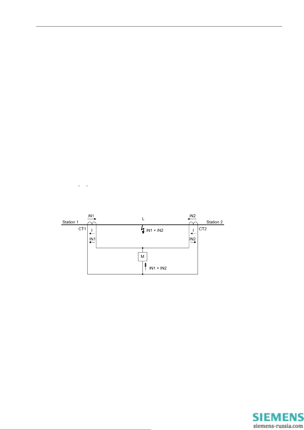
2.2 Phase Comparison Protection and Ground Differential Protection
2.2.3 Ground Current Differential Protection in Grounded Systems
The ground current differential protection of the 7SD80 operates as a stabilized (restrained) differential protection in grounded systems. The two 7SD80 devices exchange the phasors of the ground currents and the associated restraining quantities over their protection interfaces. The restraining currents and the current phasors
are summed up in each device and compared to a pickup characteristic. In the event of an internal short-circuit,
the associated circuit breaker is tripped.
2.2.3.1 Description
Basic Principle / Influencing Variables
In healthy operation, both ends of a line carry the same current. This current flows into one side of the considered zone and leaves it again on the other side. A difference in current is a clear indication of a fault within this
line section.
If the actual current transformation ratios are the same, the secondary windings of the current transformers CT1
and CT2 at the line ends can be connected to form a closed electric circuit with a secondary current I; a measuring element M which is connected to the electrical balance point remains at zero current in healthy operation.
Functions
When a fault occurs in the zone limited by the transformers, a current i
currents I
+ I2 flowing in from both sides is fed t o the measuring element. As a result, the simple circuit ensures
1
+ i2 which is proportional to the fault
1
reliable tripping of the protection if the fault current flowing into the protected zone during a fault is high enough
for the measuring element M to respond.
Figure 2-10 Basic principle of the differential protection for a line with two ends
This principle only applies to the primary system as long as quadrature-axis components of current are negligible. Quadrature-axis components of current can be caused by line capacitances or excitation currents of
transformers and parallel reactors.
The secondary currents which are applied to the devices via the current transformers, are subject to measuring
errors caused by the response characteristic of the current transformers and the input circuits of the devices.
Transmission errors such as signal jitters can also cause deviations of the measured quantities. As a result of
all these influences, the total sum of all currents processed in the devices in healthy operation is not exactly
zero. The ground current differential protection is stabilized against these influences.
Additional measuring errors which may arise in the device itself by hardware tolerances, calculation tolerances,
deviations in time or due to the „quality“ of the measured quantities such as harmonics and deviations in frequency, are also estimated by the device and increase the local self-restraining quantity automatically. Here,
the permissible variations in the protection data transmission and processing periods are also considered.
For transient inrush currents the devices have a separate inrush current restraint feature.
SIPROTEC, 7SD80, Manual
E50417-G1140-C474-A1, Release date 09.2011
59
Page 60
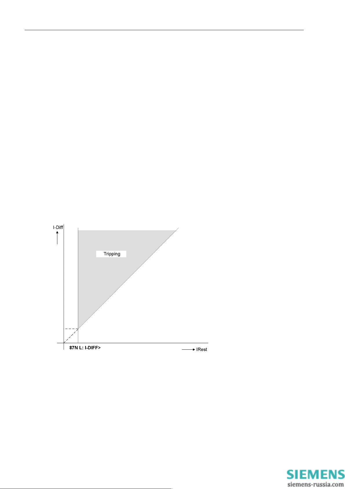
Functions
2.2 Phase Comparison Protection and Ground Differential Protection
Evaluation of Measured Values
The ground current differential protection in grounded systems evaluates the sum of the ground current phasors.
Each device calculates a ground current at each end of the protected object (fundamental component of the
ground current) and transmits it to the partner device. The received and the locally measured ground current
phasor is added to the ground differential current. The ground differential current value equals the fault current
that the differential protection system „sees“. In the ideal case, it equals the short-circuit current. In healthy operation, the differential current value is low and for lines about similar to the capacitive charging current.
The restraining quantity counteracts the ground differential current. It is the total of the maximum measured
errors at the ends of the protected object and is calculated from the current measured quantities and power
system parameters that were set. Therefore, the highest possible error value of the current transformers within
the nominal range and/or the short-circuit current range is multiplied with the current flowing through each end
of the protected object. The total value, including the measured internal errors, is then transmitted to the other
end. This is the reason why the restraint current is a replica of the greatest possible measurement error of the
entire differential protection system.
The pickup characteristic of the differential protection is derived from the restraining characteristic I
diff
= I
rest
(45°
curve) which is cut off below the setting value 87N L: I-DIFF>. It complies with the equation
I
= 87N L: I-DIFF> + Σ (current transformer errors and other measuring errors).
rest
If the calculated differential current exceeds the pickup threshold and the greatest possible measurement error,
the fault must be internal (grayed area in the illustration).
60
Figure 2-11 Pickup characteristic of the ground differential protection
If it is desired that an internal fault should initiate a TRIP command and additionally a local current of a specific
quantity should exist, the value of this current can be set at address 1225 87N L: I>RELEAS. The default
setting for this parameter is zero so that this additional criterion does not become effective.
The differential current and the restraint current 3I0diff and 3I0restr are included in the fault record.
E50417-G1140-C474-A1, Release date 09.2011
SIPROTEC, 7SD80, Manual
Page 61
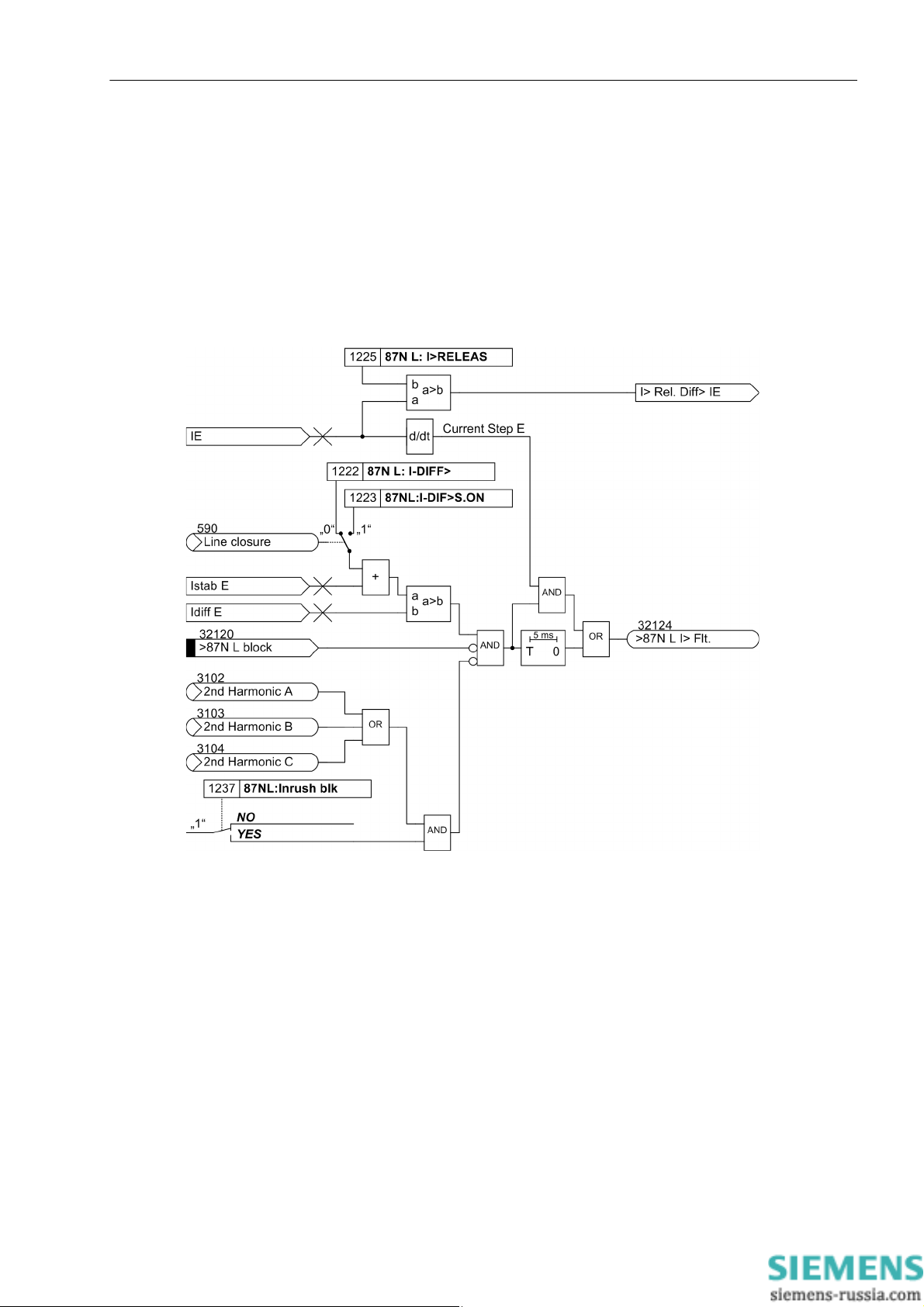
Blocking / Interblocking
The ground current differential protection can be blocked via a binary input. The blocking at one end of a protected object affects all ends via the communications link (interblocking). If the overcurrent protection is configured as an emergency function, all devices will automatically switch to this emergency operation mode.
Pickup Logic
The following figure illustrates the pickup logic of the ground current differential protection for grounded systems.
Functions
2.2 Phase Comparison Protection and Ground Differential Protection
Figure 2-12 Ground current differential protection pickup, grounded system
Y ou will find the logic diagram for the general pickup of the differential protection and the differential protection
tripping in Section 2.2.5.
SIPROTEC, 7SD80, Manual
E50417-G1140-C474-A1, Release date 09.2011
61
Page 62

Functions
2.2 Phase Comparison Protection and Ground Differential Protection
2.2.3.2 Setting Notes
General
The operating mode of the ground differential protection depends on the neutral point treatment in the protected
zone. In grounded systems, address 207 SystemStarpoint must be set to Grounded.
The ground differential protection can be switched ON or OFF at address 1221 87N L: Protect.. This requires the ground differential protection to be set to Enabled at address 112 87 DIFF.PROTEC.. The setting
Alarm only is only relevant for ground fault detection in resonant-grounded or isolated systems.
If a device is switched off or if the ground differential protection is disabled or blocked in a device, calculation
of measured values becomes impossible. The entire ground differential protection system of both ends is
blocked in this case.
Pickup Value Ground Current Differen t ial Pro tecti on
The current sensitivity is set at address 1222 87N L: I-DIFF>. It is determined by the entire current flowing
into a protected zone in case of a fault. This is the total fault current regardless of how it is distributed between
the ends of the protected obj ect.
This pickup value must be set to a value that is higher than the total steady-state quadrature-axis component
of current of the protected object. For cables and long overhead lines, the charging current has to be considered in particular. It is calculated from the operational capacitance (see Section 2.2.2.2).
Time Delays
Considering the variations of voltage and frequency, the value set should be at least 2,5 to 3 times higher than
the calculated charging current. Moreover, the pickup value should not be smaller than 15 % of the primary
rated current of the largest transformer in the protection configuration.
If setting is performed from a personal computer using DIGSI, the parameters can be set either as primary or
as secondary quantities. If secondary quantities are set, all currents must be converted to the secondary side
of the current transformers.
In special application cases, it may be advantageous to delay the tripping of the differential protection using an
additional timer, e.g. in case of reverse interlocking. The time delay 87N L: T-DELAY (address 1224) is only
started upon detection of an internal fault. This parameter can only be set in DIGSI at Display Additional Set-
tings.
With the inrush current restraint activated, the time delay 87N L: T-DELAY must be at least 20 ms for the
blocking by the inrush current restraint to be effective.
If it is desired that a TRIP command is generated in the event of an internal fault only if simultaneously the
current of the local line end has exceeded a specific quantity, then this current threshold can be set for enabling
the differential protection TRIP at address 1225 87N L: I>RELEAS. This parameter can only be set in DIGSI
at Display Additional Settings.
62
E50417-G1140-C474-A1, Release date 09.2011
SIPROTEC, 7SD80, Manual
Page 63
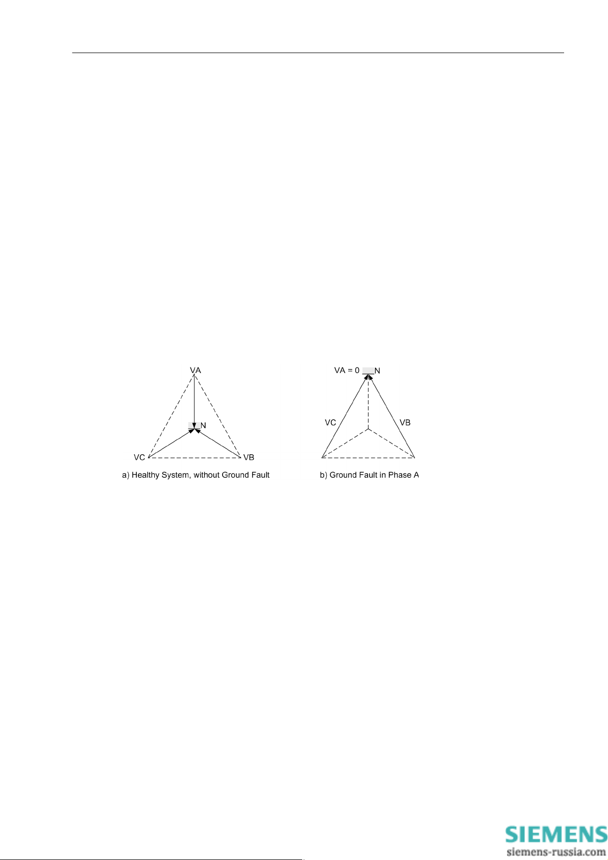
Functions
2.2 Phase Comparison Protection and Ground Differential Protection
2.2.4 Ground Fault Differential Protection in Resonant-grounded/Isolated Systems
The ground fault differential protection can be applied in power systems whose starpoint is not grounded or
grounded through an arc suppression coil (Petersen coil). It is based on the power values. Th is requires the
phase voltages or the 3V0 voltage (Appendix A.3, Figure A-11) to be connected to the devices at both ends of
the protected object.
2.2.4.1 Description
General
Single-phase ground faults are not detected by the short-circuit protection since no short circui t current flow s.
The power system operation is not immediately affected by a ground fault (the voltage triangle is maintained,
Figure 2-13). Therefore, fast tripping is usually not required or desired. The ground fault is to be detected, indicated and the affected piece of equipment is to be localized, if possible, eliminating the ground fault by initiating appropriate switching operations.
The 7SD80 enables the precise localization of the piece of equipment (line) affected by the ground fault.
In resonant-grounded systems, a core balance current transformer must be used to detect the ground current.
Figure 2-13 Ground fault in non-grounded neutral system
Pickup
Pickup occurs when the settable threshold for the displacement voltage 3·V
state measured quantities, the ground fault detection can be delayed by a configurable time after the displacement voltage has occurred.
Determination of the Phase Affected by the Ground Fault
Following pickup caused by the displacement voltage, the phase affected by the ground fault is determined first.
T o do this, the individual phase-to-ground voltages are measured. If the voltage magnitude for any given phase
is below the setting value V
, that phase is detected as the ground faulted phase as long as the remaining
min
phase-to-ground voltages are simultaneously above the setting value V
is exceeded. To obtain steady-
0
.
max
SIPROTEC, 7SD80, Manual
E50417-G1140-C474-A1, Release date 09.2011
63
Page 64

Functions
2.2 Phase Comparison Protection and Ground Differential Protection
Sensitive Ground Fault Direction Determinati on
The direction of the ground fault can be determined from the direction of the ground fault current in relation to
the displacement voltage. The only restriction is that the active or reactive current components must be available with sufficient magnitude at the point of measurement.
In networks with isolated starpoint, the ground fault current flows as capacitive current from the healthy lines
via the measuring point to the point of ground fault. For the determination of the direction the capacitive reactive
power is most relevant.
In networks with arc suppression coils, the Petersen coil superimposes a corresponding inductive current on
the capacitive ground fault current when a ground fault occurs, so that the capacitive current at the point of fault
is compensated. Depending on the measuring point in the system the resultant measured current may be inductive or capacitive. Therefore, the reactive current is not suited for direction determination of the ground current. In this case, only the ohmic (active) residual current which results from the losses of the Petersen coil can
be used for direction determination. This residual ground fault residual current is only about some per cent of
the capacitive ground fault current.
The active and reactive component of the power is decisive for the ground fault protection pickup.
A fault in forward direction must be detected at both ends of the protected object for the ground fault differential
protection to pick up.
In case of a single feeder, the residual current per watt at the opposite end of the infeed can be so weak that it
is impossible to determine the direction at that end. In this case, the amplitudes of the active currents of the two
ends are additionally compared to initiate pickup and localize the ground fault.
Pickup Logic
The amplitude of the active current (resonant-grounded system) and the reactive current (for isolated starpoint)
are included in the fault record. The local wattmetric ground current or reactive current is recorded as Iee1, the
wattmetric ground current or the reactive current of the opposite end as Iee2.
The following figure shows the pickup logic of the ground fault differential protection resonant-grounded or isolated systems.
64
E50417-G1140-C474-A1, Release date 09.2011
SIPROTEC, 7SD80, Manual
Page 65

Functions
2.2 Phase Comparison Protection and Ground Differential Protection
Figure 2-14 Ground fault differential protection pickup, isolated/resonant-grounded system
SIPROTEC, 7SD80, Manual
E50417-G1140-C474-A1, Release date 09.2011
65
Page 66

Functions
2.2 Phase Comparison Protection and Ground Differential Protection
If only the V0 voltage is connected, only parameter 1226 87N L: 3V0> is effective. The threshold checks 87N
L:Vph-g min and 87N L:Vph-g max (parameter 1227 and 1228) are not relevant.
You will find the logic diagram for the differential protection trip in Section 2.2.5.
2.2.4.2 Setting Notes
General
The operating mode of the ground differential protection depends on the neutral point treatment in the protected
zone. In resonant-grounded or isolated system, you have to set Peterson-C.Gnd. or Isolated at address
207 SystemStarpoint.
The ground differential protection can be switched ON or OFF at address 1221 87N L: Protect.. If set to
Alarm only, an indication will be output when a fault is detected. Tripping is not initiated. This requires the
ground differential protection to be set to Enabled at address 112 87 DIFF.PROTEC..
If a device is switched off at any end of the protected object or if the protection interface communication is interrupted, a calculation of measured values becomes impossible. The function then operates locally and only
issues directional indications and pickup indications but no pickup and tripping indications of the ground fault
differential protection.
Pickup Values
The pickup threshold of the displacement voltage is set in address 1226 87N L: 3V0>.
At address 1229 87N L: IN(s)> you can enter the minimum current for direction determination. The pickup
current is to be set as high as possible to avoid false pickup of the device provoked by unbalanced currents in
the system and by current transformers. Dependent on the grounding of the network starpoint, the magnitude
of the capacitive ground fault current (for isolated networks) or the wattmetric residual current (for compensated
networks) is decisive.
In isolated systems, a ground fault in a cable will allow the total capacitive ground fault currents of the entire
electrically connected system, with the exception of the faulted cable itself, to flow through the measuring point
as the latter flows directly to the fault location (i.e. not back via the measuring point). Enter about half of this
ground fault current as pickup value.
In resonant-grounded systems directional determination is made more difficult since a much larger reactive
current (capacitive or inductive) is superimposed on the critical wattmetric (active) current. Therefore, depending on the system configuration and the position of the arc-compensating coil, the total ground current supplied
to the device may vary considerably in its values with regard to magnitude and phase angle. The device, however, must evaluate only the active component of the ground fault current, the ground fault residual current,
that is I
all the instrument transformers . Furthermore, the device must not be set to operate too sensitive. When applying this function in resonant-grounded systems, a reliable direction determination can only be achieved when
toroidal current transformers are connected. Here the following rule of thumb applies: set the value to half the
expected measured current, whereby only the residual wattmetric current is used. Residual wattmetric current
predominantly derives from losses of the Petersen coil.
·cosϕ. This requires extremely high accuracy, particularly with regard to phase angle measurement of
E
66
For phase determination 87N L:Vph-g min (address 1227) is the criterion that applies to the ground-faulted
phase if simultaneously the other two phase voltages 87N L:Vph-g max (address 1228) have been exceeded. Accordingly, the setting 87N L:Vph-g min must be set smaller than the minimum phase-to-ground
voltage that occurs during operation. This setting, too, is uncritical. 40 V (default setting) should always be correct. 87N L:Vph-g max must be greater than the maximum phase-to-ground voltage occurring during operation, but less than the minimum phase-to-phase voltage occurring during operation. For V
= 100 V , the value
N
must therefore be 75 V (default setting). The definite detection of the phase affected by the ground fault is a
further prerequisite for alarming a ground fault. When connecting the voltage V0 (Appendix A.3, Figure A-11),
the check of the phase voltages does not take place.
E50417-G1140-C474-A1, Release date 09.2011
SIPROTEC, 7SD80, Manual
Page 67

2.2 Phase Comparison Protection and Ground Differential Protection
Time Delays
The ground fault is detected and reported only when the displacement voltage has applied for at least the time
87N L:TD-F.det. (address 1230). This stabilizing time also takes effect when ground fault conditions
change (e.g. change of direction).
The tripping can be delayed via the time delay 87N L:TripDelay (address1231).
With the inrush current restraint activated, the time delay 87N L:TripDelay must be at least 20 ms for the
blocking by the inrush current restraint to be effective.
2.2.5 Differential Protection Pickup Logic and Tripping Logic
2.2.5.1 Description
Pickup Logic
Once the differential protection function has reliably registered a fault within its tripping zone, the signal
“87(N)L Gen.Flt.“ (general pickup of the differential protection) is generated. For the differential protection
function itself, this pickup signal is of no concern since the tripping conditions are available at the same time.
This signal, however, is required to initiate the internal or external supplementary functions, e.g. fault recording,
automatic reclosing.
Functions
Figure 2-15 General pickup
SIPROTEC, 7SD80, Manual
E50417-G1140-C474-A1, Release date 09.2011
67
Page 68

Functions
2.2 Phase Comparison Protection and Ground Differential Protection
Tripping Logic
The following figure shows the tripping logic of the differential protection.
Figure 2-16 Differential protection trip
If the pickup signals apply for longer than the configurable trip time delay, the differential protection trips.
2.2.6 87 Differential Protection
The following tables provide an overview of the parameters and information of the functions:
- phase comparison protection
- Ground current differential protection in grounded systems
- ground fault differential protection in resonant-grounded/isolated systems
68
E50417-G1140-C474-A1, Release date 09.2011
SIPROTEC, 7SD80, Manual
Page 69

Functions
2.2 Phase Comparison Protection and Ground Differential Protection
2.2.6.1 Settings
Addresses which have an appended "A" can only be changed with DIGSI, under "Display Additional Settings".
The table indicates region-specific default settings. Column C (configuration) indicates the corresponding sec-
ondary nominal current of the current transformer.
Addr. Parameter C Setting Options Default Setting Comments
1201 87L PCC-Prot. OFF
ON
1202 87L Idyn> 1A 0.20 .. 20.00 A; ∞ 0.33 A Dynamic trip threshold
5A 1.00 .. 100.00 A; ∞ 1.65 A
1203 87L Idyn close> 1A 0.20 .. 20.00 A; ∞ 0.33 A Dynamic trip threshold line
5A 1.00 .. 100.00 A; ∞ 1.65 A
1204 87L Isteady> 1A 0.50 .. 20.00 A; ∞ 1.33 A Steady pick up threshold
5A 2.50 .. 100.00 A; ∞ 6.65 A
1205 87L I min 1A 0.10 .. 20.00 A; ∞ 1.00A Minimal phase current
5A 0.50 .. 100.00 A; ∞ 5.00 A
ON Phase current comparison
protection
closure
1206 87L Trip Delay 0.00 .. 0.10 se c 0.00 sec Trip Delay
1207 87L Man. Close DELAYED
UNDELAYED
DELAYED Trip response after manual
close
1208 87L: T EFdetect 0.00 .. 32.00 sec 0.00 sec Evolving fault detect.time
1ph faults
1214 87L:Inrush blk. NO
NO Inrush blocking
YES
1221 87N L: Protect. OFF
ON 87N L protection
ON
Alarm Only
1222 87N L: I-DIFF> 1A 0.10 .. 20.00 A 0.30 A 3I0-DIFF> Pickup value
5A 0.50 .. 100.00 A 1.50 A
1224A 87N L: T-DELAY 0.00 .. 300.00 sec; ∞ 0.00 sec 3I0-DIFF Trip time delay
1225A 87N L: I>RELEAS 1A 0.00 .. 20.00 A 0.00 A Min.current to release 3I0-
5A 0.00 .. 100.00 A 0.00 A
DIFF-Trip
1226 87N L: 3V0> 5 .. 150 V 50 V 3V0> pickup
1227 87N L:Vph-g min 10 .. 100 V 40 V Vph-g min of faulted phase
1228 87N L:Vph-g max 10 .. 100 V 75V Vph-g max of healthy
phases
1229 87N L: IN(s)> 0.003 .. 1.000 A 0.050 A IN(s)> to release direction-
al element
1230 87N L:TD-F.det. 0.00 .. 320.00 sec 1.00 sec Time delay for fault detec-
tion
1231 87N L:TripDelay 0.00 .. 320.00 sec 0.00 sec Trip Delay
1233 CT Err. I1 0.003 .. 1.600 A 0.050 A Current I1 for CT Angle
Error
1234 CT Err. F1 0.0 .. 5.0 ° 0.0 ° CT Angle Error at I1
SIPROTEC, 7SD80, Manual
E50417-G1140-C474-A1, Release date 09.2011
69
Page 70

Functions
2.2 Phase Comparison Protection and Ground Differential Protection
Addr. Parameter C Setting Options Default Setting Comments
1235 CT Err. I2 0.003 .. 1.600 A 1.000 A Current I2 for CT Angle
Error
1236 CT Err. F2 0.0 .. 5.0 ° 0.0 ° CT Angle Error at I2
1237 87NL:Inrush blk NO
NO Inrush blocking
YES
2.2.6.2 Information List
No. Information Type of In-
Comments
formation
3190 Test 87 IntSP 87 Set test state of 87
3191 Commiss.87 IntSP 87 Set Commissioning state of 87
3192 Test 87 remote OUT 87 Remote relay in test state
3193 Comm. 87 active OUT 87 Commissioning state is active
3197 >Test 87 ON SP 87 >Set test state of 87
3198 >Test 87 OFF SP 87 >Reset test state of 87
3199 Test 87 ON/off IntSP 87 Test state of 87 ON/OFF
3200 Test 87 ONoffBI IntSP 87 Test state ON/OFF via BI
3260 >Comm. 87 ON SP 87 >Commissioning state ON
3261 >Comm. 87 OFF SP 87 >Commissioning state OFF
3262 Comm 87 ON/OFF IntSP 87 Commissioning state ON/OFF
3263 Comm 87 ONoffBI IntSP 87 Commissioning state ON/OFF via BI
32100 >87L block SP >87L Protection blocking signal
32102 87L active OUT 87L Protection is active
32103 87L Fault A OUT 87L Fault detection A
32104 87L Fault B OUT 87L Fault detection B
32105 87L Fault C OUT 87L Fault detection C
32107 87L is blocked OUT 8 7L Protection is blocked
32108 87L is OFF OUT 87L Protection is switched off
32109 87L allow A OUT 87L A released
32110 87L allow B OUT 87L B released
32111 87L allow C OUT 87L C released
32112 87 CTRatioAlarm OUT 87 CT primary ratio is too high
32113 87L receive blk OUT 87L receive blocking
32114 87L send blk OUT 87L send blocking
32115 87L IDYN> A OUT 87L IDYN> A
32116 87L IDYN> B OUT 87L IDYN> B
32117 87L IDYN> C OUT 87L IDYN> C
32118 87L ISTAT> A OUT 87L ISTAT> A
32119 87L ISTAT> B OUT 87L ISTAT> B
32120 >87N L block SP >87N L Protection blocking signal
32121 >87N L active OUT >87N L: Protection is active
32122 87(N)L Gen.Flt. OUT 87(N)L Fa ult detection
32124 >87N L I> Flt. OUT >87N L: Fault detection of I-Diff>
32125 87(N)L Gen.TRIP OUT 87(N)L General TRIP
70
E50417-G1140-C474-A1, Release date 09.2011
SIPROTEC, 7SD80, Manual
Page 71

Functions
2.2 Phase Comparison Protection and Ground Differential Protection
No. Information Type of In-
formation
32126 87N L block OUT 87N L: Protection is blocked
32127 87N L OFF OUT 87N L: Protection is switched off
32128 87N L 3V0> OUT 87N L: detection 3V0> pickup
32129 87N L Forward OUT 87N L: detection Forward
32130 87N L Reverse OUT 87N L: detection Reverse
32131 87N L UndefDir OUT 87N L: detection Undef. Direction
32132 87N L rec. blk OUT 87N L: receive blocking
32133 87N L send blk OUT 87N L: send blocking
32134 87N L PU OUT 87N L: pickup
32150 87L ISTAT> C OUT 87L ISTAT> C
Comments
2.2.7 Differential Protection Test and Commissioning
2.2.7.1 Differential Protection Test
General
If differential protection test mode (test mode in the following) is activated, the differential protection is blocked
in the entire system. Depending on the configuration, the overcurrent protection acts as emergency function.
In the local device all currents from the other devices are set to zero. The local device only evaluates the locally
measured currents, interprets them as differential current but does not send them to the other devices. This
enables measuring the thresholds of the differential protection. Moreover, the test mode prevents in the local
device that tripping of the differential protection generates a transfer trip signal.
The test mode can be activated/deactivated as follows:
• Operation panel: Menu Control/Taggings/Set: „Test mode“
• Via binary inputs (no. 3197 „>Test 87 ON“, no. 3198 „>Test 87 OFF“) if this was routed
• In DIGSI with Control / Taggings: „Diff: Test mode“
The test mode status of the other device of the line protection system is indicated on the local device by the
indication „Test 87 remote“ (No. 3192).
Mode of Operation
Below, the logic is shown in a simplified way:
Figure 2-17 Logic diagram of the test mode
SIPROTEC, 7SD80, Manual
E50417-G1140-C474-A1, Release date 09.2011
71
Page 72

Functions
2.2 Phase Comparison Protection and Ground Differential Protection
Depending on the way used for controlling the test mode, either the indication „Test 87 ON/off“ (no. 3199)
or „Test 87 ONoffBI“ (no. 3200) is generated. The way used for deactivating the test mode always has to
be identical to the way used for activating. The indication „Test 87“ (no. 3190) is generated independently
of the chosen way. When deactivating the test mode via the binary inputs, a time delay of 500 ms becomes
effective.
The following figures show possible variants for controlling the binary inputs. If a switch is used for the control
(Figure 2-19), it has to be observed that binary input „>Test 87 ON“ (no. 3197) is parameterized as NO
contact and that binary input „>Test 87 OFF“ (no. 3198) is parameterized as NC contact.
Figure 2-18 External push-button wiring for controlling the differential protecti on test mode
Bu1 Push-button „Switching off the differential protection test mode“
Bu2 Push-button „Switching on the differential protection test mode“
Figure 2-19 External switch wiring for controlling the differential protection test mode
S Switch „Switching the differential protection test mode on/off“
1) Binary input as make contact
2) Binary input as break contact
If a test switch is to be used for changing to test mode, we recommend the following procedure:
• Block the differential protection via a binary input.
• Use the test switch to activate/deactivate the test mode.
• Reset the blocking of the differential protection via the binary input.
72
E50417-G1140-C474-A1, Release date 09.2011
SIPROTEC, 7SD80, Manual
Page 73

2.2 Phase Comparison Protection and Ground Differential Protection
2.2.7.2 Differential Protection Commissioning
General
In differential protection commissioning mode (commissioning mode in the following) the differential protection
does not generate TRIP commands. The commissioning mode is intended to support the commissioning of the
differential protection.
You can check:
• transformer polarity, using the constellation measured values
• differential currents
• restraint currents
By editing parameters, the operating point of the differential protection can be changed without any risk up to
the generation of a pickup.
Functions
Figure 2-20 Commissioning mode - overview
The commissioning mode is activated on a device of the protective device constellation and also affects the
device at the other end of the protected object (indication no. 3193„Comm. 87 active“). The commissioning
mode has to be deactivated on the device on which it was activated.
The commissioning mode can be activated/deactivated as follows:
• Operation panel: Menu Control/Taggings/Set: „Commissioning mode“
• Via binary inputs (no. 3260 „>Comm. 87 ON“, no. 3261 „>Comm. 87 OFF“) if this was routed
• In DIGSI with Control / Taggings: „Diff: Commissioning mode“
Mode of Operation
Below, the logic is shown in a simplified way:
Figure 2-21 Logic diagram of the commissioning mode
SIPROTEC, 7SD80, Manual
E50417-G1140-C474-A1, Release date 09.2011
73
Page 74
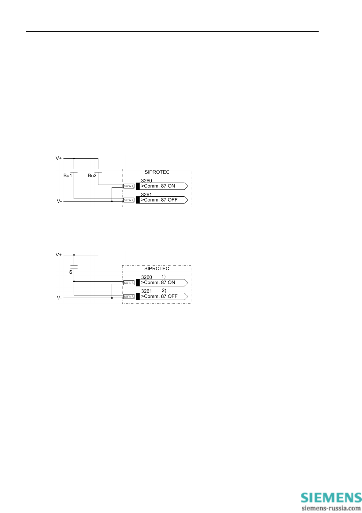
Functions
2.2 Phase Comparison Protection and Ground Differential Protection
There are two ways to set the commissioning mode. The first way is to use a command (commissioning mode
on / commissioning mode off) which is generated either when operating the integrated keypad or when operating with DIGSI. The second way is to use the binary inputs (no. 3260 „>Comm. 87 ON“, no. 3261 „>Comm.
87 OFF“).
Depending on the way used for controlling the commissioning mode, either the indication „Comm 87 ON/OFF“
(no. 3262) or „Comm 87 ONoffBI“ (no. 3263) is generated. The way used for deactivating the commissioning
mode always has to be identical to the way used for activating. The indication „Commiss.87“ (no. 3191) is
generated independently of the chosen way.
The following figures show possible variants for controlling the bin ary inputs. If a switch is used for control
(Figure 2-23), it has to be observed that binary input „>Comm. 87 ON“ (no. 3260) is parameterized as NO
contact and that binary input „>Comm. 87 OFF“ (no. 3261) is parameterized as NC contact.
Figure 2-22 External push-button wiring for controlling the differential protection commissioning mode
Bu1 Push-button „Switching off the differential protection commissioning mode“
Bu2 Push-button „Switching on the differential protection commissioning mode“
Figure 2-23 External switch wiring for controlling the differential protection commissioning mode
S Switch „Switching the differential protection commissioning mode on/off“
1) Binary input as make contact
2) Binary input as break contact
74
E50417-G1140-C474-A1, Release date 09.2011
SIPROTEC, 7SD80, Manual
Page 75
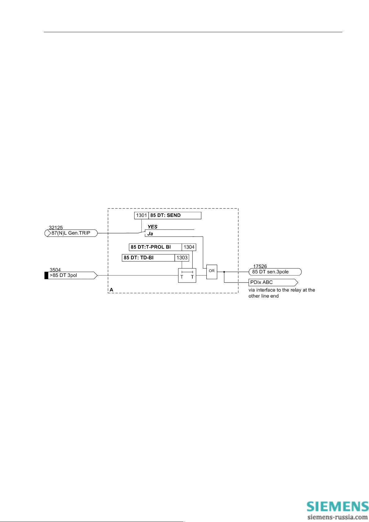
2.3 Breaker Intertrip and Remote Tripping
The 7SD80 device allows transmitting a trip command created by the local differential protection to the other
end of the protected object (intertripping). Likewise, any desired command of another internal protection function or of an external protection, monitoring or control equipment can be transmitted for remote tripping.
2.3.1 Description
Transmit Circuit
The transmission signal can originate from two different sources (Figure 2-24). If the parameter 85 DT: SEND
is set to YES, each tripping command of the differential protection is routed immediately to the transmission
function „ITrp.sen. A“ to "...C“ (intertrip) and transmitted via the protection data interfaces and c ommunication
links.
The send function can be triggered via binary input „>85 DT 3pol“ (remote tripping). The transmission signal
can be delayed with 85 DT: TD-BI and prol onged with 85 DT:T-PROL BI.
Functions
2.3 Breaker Intertrip and Remote Tripping
Figure 2-24 Logic diagram of the intertrip — transmission circuit
Receive Circuit
On the receiving end the signal can lead to a trip. Alternatively, it can also cause an alarm only. In this way it
is possible to determine for each end of the protected object whether the received signal is to trip at this particular end or not.
If the received signal is to cause the trip, it will be forwarded to the tripping logic of the device.
SIPROTEC, 7SD80, Manual
E50417-G1140-C474-A1, Release date 09.2011
75
Page 76

Functions
2.3 Breaker Intertrip and Remote Tripping
Figure 2-25 Logic diagram of the intertrip — receiving circuit
Additional Options
Since the signals for remote tripping can be set to just generate an indication, any other desired signals can be
transmitted as well. After the binary input(s) have been activated, the signals which are set to cause an alarm
at the receiving end are tr ansmitted. These alarm s can in turn execute any desired actions at the receiving end.
2.3.2 Setting Notes
General
The intertrip function for tripping caused by the differential protection can be activated (YES) or deactivated (NO)
at address 1301 85 DT: SEND.
To ensure that the faulted line is cleared, the intertrip function must be activated. In some applications, e.g. a
single feed, it may be desirable to switch off the feeding end only. In such exceptional cases, the intertrip function is not needed.
Intertrip / Remote Tripping
The activated intertrip function starts automatically when the differential protection trips at only one end.
If the relevant binary inputs are allocated and activated by an external source, the intertrip signal is transmitted
as well. In this case, the signal to be transmitted can be delayed with address 1303 85 DT: TD-BI. This delay
stabilizes the originating signal against dynamic interferences which may possibly occur on the control cabling.
Address 1304 85 DT:T-PROL BI is used to extend a signal after it has been effectively injected from an ex-
ternal source.
76
The reaction of a device when receiving an intertrip/remote tripping signal is set in address 1302 85 DT:
RECEIVE. If it is desired to cause tripping, set the value Trip. If the received signal, however, is supposed to
cause an alarm only, Alarm only must be set if this indication is to be further processed externally.
E50417-G1140-C474-A1, Release date 09.2011
SIPROTEC, 7SD80, Manual
Page 77
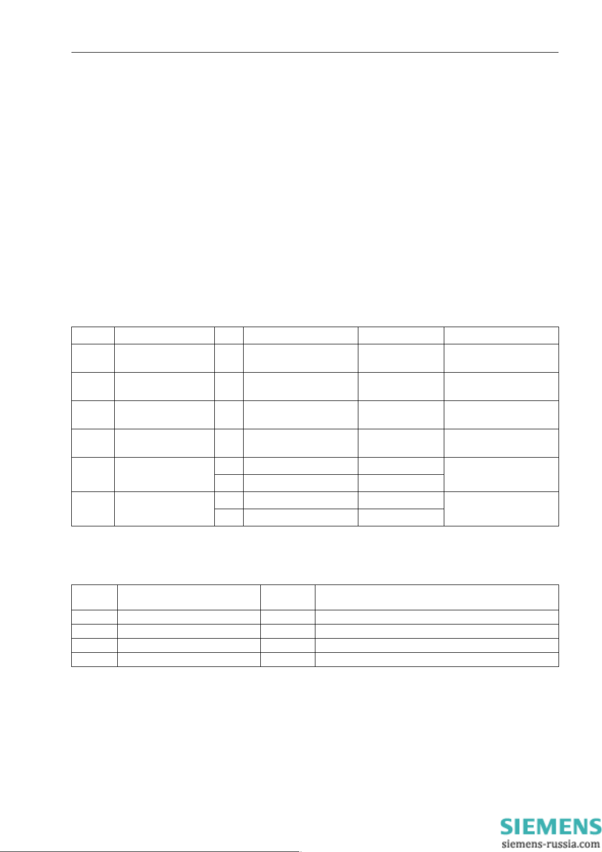
2.3 Breaker Intertrip and Remote Tripping
The setting times depend on the individual case of application. A delay is necessary if the external control signal
originates from a disturbed source and a restraint seems appropriate. Of course, the control signal has to be
longer than the delay for the signal to be effective. If the signal is processed externally at the receiving end, a
prolongation time might become necessary for the transmitting end so that the reaction desired at the receiving
end can be executed reliably.
Release Thresholds
Before the release for tripping is given, the phase and ground currents must exceed settable thresholds. You
can set these thresholds at the following addresses:
• 1305 85 DT Iph rel. for the minimum phase current
• 1306 85 DT 3I0 rel. for the minimum ground current 3I0
2.3.3 Settings
The table indicates region-specific default settings. Column C (configuration) indicates the corresponding secondary nominal current of the current transformer.
Addr. Parameter C Setting Options Default Setting Comments
Functions
1301 85 DT: SEND YES
NO
1302 85 DT: RECEIVE Alarm only
Trip
1303 85 DT: TD-BI 0.00 .. 30.00 sec 0.00 sec 85 DT: Delay for intertrip
1304 85 DT:T -PROL BI 0.00 .. 30.00 sec 0.00 sec 85 DT : Prol. for intertrip via
1305 85 DT Iph rel. 1A 0.0 .. 25.0 A; ∞ 0.0 A 85 DT minimal Phase
5A 0.0 .. 125.0 A; ∞ 0.0 A
1306 85 DT 3I0 rel. 1A 0.0 .. 25.0 A; ∞ 0.0 A 85 DT minimal 3I0 Current
5A 0.0 .. 125.0 A; ∞ 0.0 A
YES 85 DT: State of transm.the
intertrip cmd
Trip 85 DT: React.if intertrip
cmd is receiv.
via bin.input
bin.input
Current to rel. trip
to rel. trip
2.3.4 Information List
No. Information Type of In-
formation
3504 >85 DT 3pol SP >86 DT: >Intertrip 3 pole signal input
3517 85 DT Gen. TRIP OUT 85 DT: General TRIP
17525 85 DT rec.3pole OUT 85 DT: Received 3pole
17526 85 DT sen.3pole OUT 85 DT: Sending 3pole
Comments
SIPROTEC, 7SD80, Manual
E50417-G1140-C474-A1, Release date 09.2011
77
Page 78

Functions
2.4 Backup Overcurrent
2.4 Backup Overcurrent
The 7SD80 features an overcurrent protection function which can be used as either backup or emergency overcurrent protection. All elements are independent of each other and can be combined as desired.
The overcurrent protection has two overcurrent elements with definite trip time and one overcurrent protection
element with inverse time delay for the phase currents and for the ground current. These elements operate directionally or non-directionally.
One additional definite-time overcurrent protection element always operates non-directionally. It features an
additional release input and can act as emergency element if the other elements are used for backup purposes.
The elements are independent of each other and can be combined in any way. Blocking by external criteria via
binary inputs is possible.
2.4.1 Operating Modes
Emergency Overcurrent Protection
The differential protection as a whole can only operate correctly if both devices receive the data of the respective other device properly. The emergency overcurrent protection in contrast requires only the local currents.
Acting as emergency overcurrent protection, it automatically replaces the differential protection as short-circuit
protection if data communication of the differential protection is faulty (emergency operation). The differential
protection is blocked in this case.
Backup Time Overcurrent Protection
If the overcurrent protection is set as backup time overcurrent protection, it will work independently of the other
protection and monitoring functions, i.e. also independently of the differential protection. The backup overcurrent protection can also act as the only short-circuit protection if no suitable channels for the communication
between the protection devices are available yet during the initial commissioning. It can be used as busbar protection via reverse interlocking in combination with other protec tion devices or as backup protection function
for protection device failure at continuing lines.
2.4.2 Non-directional Overcurrent Protection
Measured Quantities
The phase currents are fed to the device via the input transformers of the measuring input. The ground current
3I
is calculated from the phase currents.
0
Definite Time High-set Element 50-1
Each phase current is compared with the setting value 50-B2 PICKUP after numerical filtering; the ground
current is compared with 50N-B2 PICKUP. A trip command is issued after pickup of an element and expiration
of the associated time delays 50-B2 DELAY or 50N-B2 DELAY. The dropout value is about 7 % below the
pickup value, but at least 5 % of the rated current.
Figure 2-26 shows the logic diagram of the 50-1 elements. They can be blocked via binary input „>BLOCK 50-
B2“. Additionally, the ground current element can be blocked separately via the binary input „>BLOCK 50NB2“.
78
E50417-G1140-C474-A1, Release date 09.2011
SIPROTEC, 7SD80, Manual
Page 79
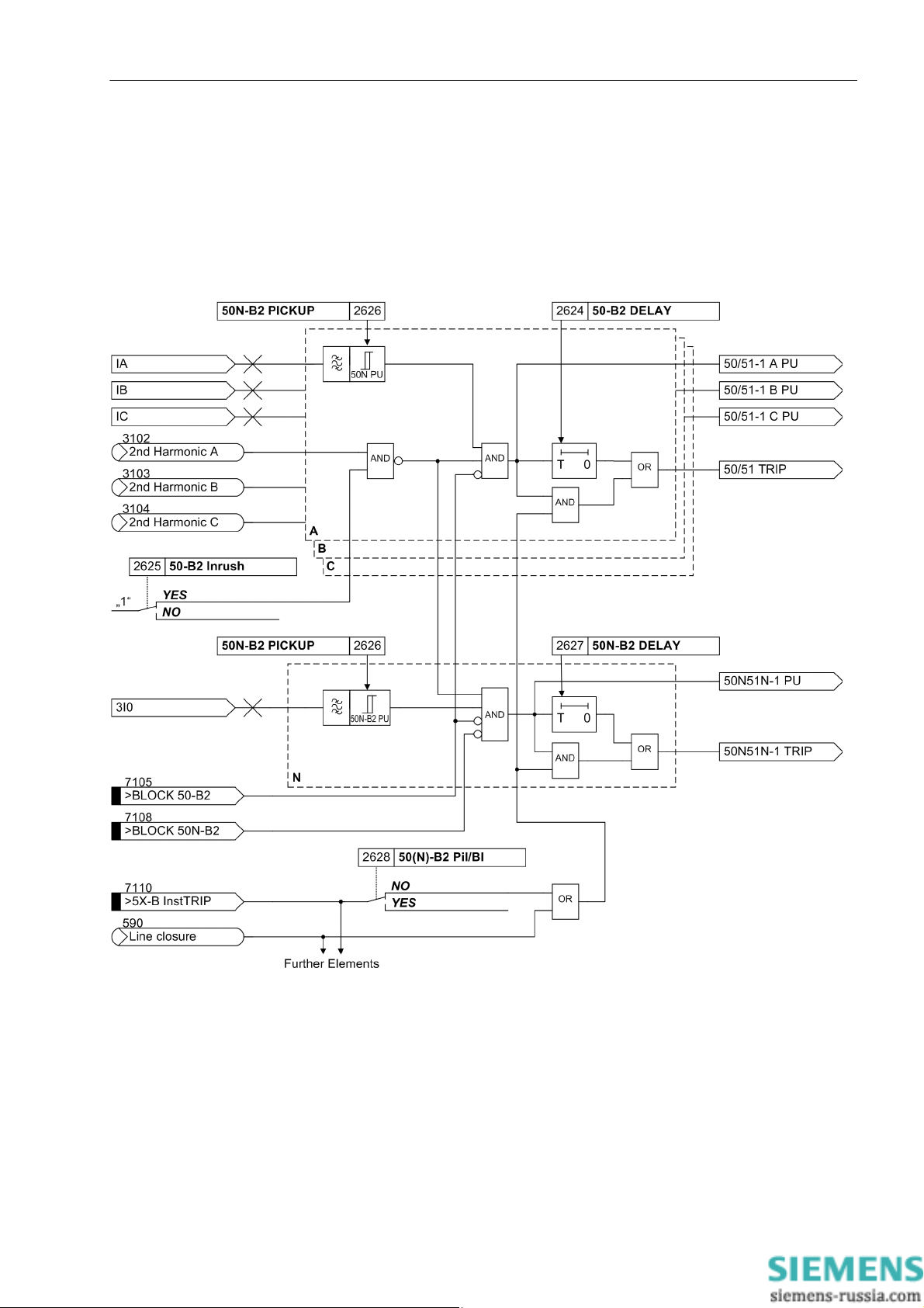
Functions
2.4 Backup Overcurrent
The binary input „>5X-B InstTRIP“ and the evaluation of the indication „switch“ (onto fault) are common to
all elements. They may, however, separately affect the phase and/or ground current elements.
Parameter 50-B1 DELAY (address 2618) determines whether a non-delayed trip of this element via binary
input „>5X-B InstTRIP“ is possible (YES) or impossible (NO). This parameter is also used for fast tripping
before reclosing
If parameter 50-B2 Inrush (address2625) is set to YES, the element is blocked.
Figure 2-26 Logic diagram of the 50-1 element
Definite Time Overcurrent Element 50-2
The logic of the overcurrent elements 50-2 is the same as the logic of the 50-1 elements described above. In all
names, -1 has to be replaced by -2. The parameter names of the 50-2 elements are listed in secti on 2.4.4.
SIPROTEC, 7SD80, Manual
E50417-G1140-C474-A1, Release date 09.2011
79
Page 80

Functions
2.4 Backup Overcurrent
Definite Time Overcurrent Element 50-3
The 50-3 element operates independently of the other elements. Its logic corresponds to the 50-1 and 50-2 elements described above, but operates non-directional only.
If parameter 50-STUB Inrush (address 2653) is set to YES, the element is blocked.
Figure 2-27 Logic diagram of the 50-3 element
Inverse Time Overcurrent Element 51
The logic of the inverse overcurrent element basically operates in the same way as the other elements. The
time delay, however , is calculated based on the type of the set characteristic, the intensity of the current and a
time multiplier (following figure). A pre-selection of the available characteristics was already carried out during
the configuration of the protection functions. Furthermore, an additiona l constant time delay 51-B AddT-
DELAY or 51N-B AddTdelay may be selected which is added to the inverse time. The possible characteristics
are shown in the Technical Data.
80
E50417-G1140-C474-A1, Release date 09.2011
SIPROTEC, 7SD80, Manual
Page 81

Functions
2.4 Backup Overcurrent
The non-directional and the directional inverse time overcurrent element 51 always uses the same characteristic curve that is parameterized via 2642 (IEC) or 2643 (ANSI). Different inverse times and additional times
can be parameterized here.
The following figure shows the logic diagram. The setting addresses of the IEC characteristic curves are shown
by way of example. In the setting notes (Section 2.4.4), the different setting addresses are described in detail.
If parameter 51-B Inrush (address 2637) is set to YES, the element is blocked.
Figure 2-28 Logic diagram of the 51 element (inverse time overcurrent protection) - example for IEC characteristic
SIPROTEC, 7SD80, Manual
E50417-G1140-C474-A1, Release date 09.2011
81
Page 82

Functions
2.4 Backup Overcurrent
Pickup Logic and Tripping Logic
The pickup signals of the individual phases (or ground) and of the individual elements are interlinked in such a
way that both the phase information and the element which has picked up are indicated (Table 2-1).
Table 2-1 Pickup signals of the single phases
Internal indication Display Output indication No.
50-2 PU A
50-1 PU A
50-3 PU A
51 PU A
50-2 PU B
50-1 PU B
50-3 PU B
51 PU B
50-2 PU C
50-1 PU C
50-3 PU C
51 PU C
50-2 PU N
50-1 PU N
50-3 PU N
51 PU N
50-1 PU A
50-1 PU B
50-1 PU C
50-1 PU N
50-2 PU A
50-2 PU B
50-2 PU C
50-2 PU N
50-3 PU A
50-3 PU B
50-3 PU C
50-3 PU N
51 PU A
51 PU B
PU C
51
51 PU N
(All pickups) „5X-B PICKUP“ 7161
2-26
2-27
2-28
2-26
2-27
2-28
2-26
2-27
2-28
2-26
2-27
2-28
2-26
2-26
2-26
2-26
2-26
2-26
2-26
2-26
2-27
2-27
2-27
2-27
2-28
2-28
2-28
2-28
„5X-B Pickup ØA“ 7162
„5X-B Pickup ØB“ 7163
„5X-B Pickup ØC“ 7164
„5X-B Pickup Gnd“ 7165
„50(N)-B2 PICKUP“ 7192
„50(N)-B1 PICKUP“ 7191
„50-STUB PICKUP“ 7201
„51(N)-B PICKUP“ 7193
82
The trip is signaled specifically for each element, e.g. „50(N)-B2 TRIP“.
E50417-G1140-C474-A1, Release date 09.2011
SIPROTEC, 7SD80, Manual
Page 83

2.4.3 Directional Overcurrent Protection
Measured Quantities
The phase currents are fed to the device via the input transformers of the measuring input. The ground current
3I
is calculated from the phase currents.
0
For the directional Iph> elements, the used measuring voltage is determined by the fault type.
The current phase-to-ground voltage is used
• for 1-phase or 3-phase faults,
• if the phase-to-ground voltage is > 4 V,
• not within the first 50 ms after short-circuit inception as the present voltage is disturbed by transients during
this time.
The saved phase-to-ground voltage is used
• for 1-phase or 3-phase faults,
• up to max. 2 sec. after saving the phasors
• if there was not pickup before short-circuit occurrence.
The unfaulted phase-to-phase voltage is used
• for 1-phase faults
• for unfaulted phase-to-ground voltages
• if the voltage value is > 70% of the rated voltage.
Functions
2.4 Backup Overcurrent
The negative-sequence system quantities V
• for 1-phase or 2-phase faults
> 50 mA and V2 > 5 V.
•if I
2
When using the negative-sequence system quantities, it is the short circuit with the higher current which determines the direction in case of two 1-phase short circuits.
If none of the above measured quantities is available, an already existing result of the direction determination
is used or the directional element is blocked for the corresponding phase.
The behavior in the even to a measuring voltage failure can be set. The elements operate directionally or nondirectionally.
The time overcurrent protection only operates directionally if all 3 phase-to-ground voltages are connected.
Address 144 must be set to connected here.
Directional Characteristic
The directional characteristic of the directional overcurrent elements is fixed. The angle difference ϕ(V
calculated from the voltage phasors and current phasors using the impedance Z
termined using the depicted directional characteristic.
and I2 are used
2
)-ϕ(I) is
= V/I and the direction is de-
SIPROTEC, 7SD80, Manual
E50417-G1140-C474-A1, Release date 09.2011
83
Page 84

Functions
2.4 Backup Overcurrent
Figure 2-29 Directional characteristic of the time overcurrent protection
Definite Time Overcurrent Element 67-1
The directional overcurrent elements basically work in the same way as the non-directional elements. Pickup,
however, depends on the result of the direction determination. The direction determination is accomplished
using the measured quantities and the corresponding directional characteristics.
67-B2 PICKUP is used as setting values for the phase current; 67N-B2 PICKUP is used for the ground current. A trip command is issued after pickup of an element and expiration of the associated time delays 67-B2
DELAY or 67N-B2 DELAY. The dropout value is approximately 7% below the pickup value, but at least 1.8%
of the nominal current, below the pickup value.
Figure 2-30 shows the logic diagram of the 67-1 elements. They can be blocked via the binary input . Additionally, the ground current element can be blocked separately via the binary input „>BLOCK 67N-TOC“.
The binary input „>5X-B InstTRIP“ and the evaluation of the indication „switch“ (onto fault) can act separately on the directional phase and/or ground element.
Parameter 67(N)-B2 Pil/BI (address 2628) determines whether a non-delayed trip of this element via
binary input „>5X-B InstTRIP“ is possible (YES) or impossible (NO). This parameter is also used for instantaneous tripping before automatic reclosing.
The indications or are created from the individual directional indications ( to ) determined specifically for the
phase or current if a valid direction was determined for a phase or ground current (forward or reverse). These
indications can then be transmitted to another device where they can cause instantaneous tripping there if an
overcurrent element of the receiving device has picked up, too. The indications must be linked via CFC to this
end.
84
E50417-G1140-C474-A1, Release date 09.2011
SIPROTEC, 7SD80, Manual
Page 85

Functions
2.4 Backup Overcurrent
Figure 2-30 Logic diagram of the 67-1 element
SIPROTEC, 7SD80, Manual
E50417-G1140-C474-A1, Release date 09.2011
85
Page 86

Functions
2.4 Backup Overcurrent
Definite Time High-set Element 67-2
The directional overcurrent element basically works in the same way as the non-directional element. Pickup,
however, depends on the result of the direction determination. The direction determination is accomplished
using the measured quantities and the corresponding directional characteristics.
67-B1 PICKUP is used as setting values for the phase current; 67N-B1 PICKUP is used for the ground current. A trip command is issued after pickup of an element and expiration of the associated time delays 67-B1
DELAY or 50N-B1 DELAY. The dropout value is approximately 7% below the pickup value, but at least 1.8%
of the nominal current, below the pickup value.
Figure 2-30 shows the logic diagram of the 67-1 elements. The same applies analogously to the high-set current
element 67-2.
Inverse Time Overcurrent Element 67-TOC
The logic of the inverse overcurrent element basically operates in the same way as that of the non-directional
element. Pickup, however, depends on the result of the direction determination. The direction determination is
accomplished using the measured quantities and the corresponding directional characteristics.
The time delay, however, is calculated based on the type of the set characteristic, the intensity of the current
and the time factor 67-TOC TD ANSI or 67N-TOC TD ANSI. Furthermore, an additional constant time delay
67-TOC AddTDel. or 67N-TOC AddTDel may be selected which is added to the inverse time. The possible
characteristics are shown in the Technical Data.
The indications or are created from the individual directional indications ( to ) determined for the phase and
ground current provided that a valid directional result (forward or reverse) was determined for the phase or
ground current. These indications can then be transmitted to another device where they can cause instantaneous tripping if an overcurrent element of the received device has picked up, too. The indications must be
linked via CFC to this end.
The following figure shows the logic diagram of the directional 67-TOC element. The setting addresses for the
IEC characteristics are shown by way of example. In the setting notes (Section 2.4.4), the different setting addresses are described in detail.
The non-directional and the directional inverse time overcurrent element 51 always uses the same characteristic curve that is parameterized via 2642 (IEC) or 2643 (ANSI). Different inverse times and additional times
can be parameterized here.
86
E50417-G1140-C474-A1, Release date 09.2011
SIPROTEC, 7SD80, Manual
Page 87

Functions
2.4 Backup Overcurrent
Figure 2-31 Logic diagram of the 67 TOC element (directional, inverse time overcurrent protection) - example for IEC
characteristic
SIPROTEC, 7SD80, Manual
E50417-G1140-C474-A1, Release date 09.2011
87
Page 88

Functions
2.4 Backup Overcurrent
Pickup Logic and Tripping Logic
The pickup signals of the individual phases (or ground) and of the individual elements are interlinked in such a
way that both the phase information and the element which has picked up are indicated (Table 2-1).
Table 2-2 Pickup signals of the single phases
Internal indication Display Output indication No.
67-1 PU A
67-2 PU A
67-TOC PU A
67-1 PU B
67-2 PU B
67-TOC PU B
67-1 PU C
67-2 PU C
67-TOC PU C
67-1 PU N
67-2 PU N
67-TOC PU N
67-1 PU A
67-1 PU B
67-1 PU C
67-1 PU N
67-2 PU A
67-2 PU B
67-2 PU C
67-2 PU N
67-TOC PU A
67-TOC PU B
67-TOC PU C
67-TOC PU N
(All pickups)
2-30
2-31
2-30
2-31
2-30
2-31
2-30
2-31
2-30
2-30
2-30
2-30
2-31
2-31
2-31
2-31
„67(N)-B2 PICKUP“ 7251
„67(N)-B1 PICKUP“ 7250
„67(N)-TOC PICK.“ 7252
The trip is signaled specifically for each element, e.g. „67(N)-B2 TRIP“.
Behavior during Measuring Voltage Failure
An element-specific parameter, e.g. 67(N)-B1 on FFM allows you to define how the directional overcurrent
protection acts when the measuring voltage fails. The overcurrent protection then works either Non-
Directional or it is .
88
E50417-G1140-C474-A1, Release date 09.2011
SIPROTEC, 7SD80, Manual
Page 89

2.4.4 Setting Notes
General
The setting notes described in the following apply to non-directional and directional overcurrent protection.
Operating Modes
You set the operating mode of the overcurrent protection elements specifically for each element. The setting
applies collectively to the corresponding phase and ground element.
50-1, 3I0> address 2620
50-2, 3I0>> address 2610
50N, 3I0p address 2630
50-3, 3I0>>> address 2650
The following settings are possible:
• If set to ON, the time overcurrent protection operates independently of the other protection functions as
backup overcurrent protection.
• If set to Only Emer. prot, the overcurrent protection operates as emergency function.
•Set to OFF, the element is disabled.
Functions
2.4 Backup Overcurrent
Direction
The elements 50-1, 50-2 and 50N operate directionally and non-directionally.
The direction is set specifically for each element. The setting applies collectively to the corresponding phase
and ground element.
50-1, 3I0> address 2621
50-2, 3I0>> add ress 2611
50N, 3I0p address 2631
The following settings are possible:
• Non-Directional
• Forward
• Reverse
The operating mode of the directional element in the event of measuring voltage failure is set specifically for
each element. The setting applies collectively to the corresponding phase and ground element.
50-1, 3I0> address 2622
50-2, 3I0>> add ress 2612
50N, 3I0p address 2632
The following settings are possible:
• Non-Directional
• BLOCKED
The 50-3 element always operates non-directionally.
SIPROTEC, 7SD80, Manual
E50417-G1140-C474-A1, Release date 09.2011
89
Page 90

Functions
2.4 Backup Overcurrent
Inrush Blocking
Y ou can specify for each element of the overcurrent protection whether the element will be blocked when inrush
is detected. The setting applies collectively to the corresponding phase and ground element.
50-1, 3I0> address 2625
50-2, 3I0>> address 2615
50N, 3I0p address 2637
50-3, 3I0>>> address 2653
Pickup Values
The elements can be combined. The pickup values are determined by the type of protected object.
The pickup values are set specifically for each element:
50-B2 PICKUP, 67-B2 PICKUP address 2623
50N-B2 PICKUP, 67N-B2 PICKUP address 2626
50-B1 PICKUP, 67-B1 PICKUP address 2613
50N-B1 PICKUP, 67N-B1 PICKUP address 2616
51-B PICKUP, 67-TOC PICKUP address 2633
51N-B PICKUP, 67N-TOC PICKUP address 2638
The setting of the current pickup value is basically determined by the maximum operational current. Pickup due
to overload must be excluded as the device operates as short-circuit protection in this mode with correspondingly short command times and not as overload protection. A pickup value setting of about 10% is recommended for line protection, and a setting of about 20% of the expected peak load is recommended for transformers
and motors.
The ground current elements detect the smallest anticipated ground fault current.
For very long lines with small source impedance or on applications with large reactances (e.g. transformers,
series reactors), the 50-2 elements can also be used for current grading. In this case, they must be set such
that they do not pickup reliably on a short circuit at the line end.
For the inverse time elements a safety margin between pickup value and setting value has already been implemented. Pick up only occurs at a current which is approximately 10% above the set value. Please bear this
in mind when specifying the setting values of the inverse time elements.
If an element is not required, set the pickup value to ∞.
90
E50417-G1140-C474-A1, Release date 09.2011
SIPROTEC, 7SD80, Manual
Page 91

Time Delays
Functions
2.4 Backup Overcurrent
The time delays are set specifically for each element:
50-B2 DELAY, 67-B2 DELAY addess 2624
50N-B2 DELAY, 67N-B2 DELAY addess 2627
50-B1 DELAY, 67-B1 DELAY addess 2614
50N-B1 DELAY, 67N-B1 DELAY addess 2617
51-B TD IEC, 67-TOC TD IEC addess 2634 (IEC characteristic)
51N-B TD IEC, 67N-TOC TD IEC addess 2639 (IEC characteristic)
51-B TD ANSI, 67-TOC TD ANSI addess 2635 (ANSI characteristic)
51N-B TD ANSI, 67N-TOC TD ANSI addess 2640 (ANSI characteristic)
They are determined by the time grading chart created for the power system. If used as emergency overcurrent
protection, shorter tripping times are advisable as this function is only activated in the case of the loss of the
local measuring voltage.
The times for the ground current elements can be set shorter, according to a separate time grading chart for
ground currents.
You can set additional time delays for definite-time elements with IEC characteristic.
51-B AddT-DELAY, 67-TOC AddTDel. addess 2636
51N-B AddTdelay, 67N-TOC AddTDel addess 2641
Instantaneous Tripping via Binary Input
Binary input „>5X-B InstTRIP“ allows you to bypass the time delays. The binary input applies to all elements collectively.
You can specify for each element whether instantaneous tripping takes effect. The setting applies collectively
to the corresponding phase and ground element.
50-1, 3I0> address 2628
50-2, 3I0>> add ress 2618
50N, 3I0p address 2644
The following settings are possible:
• If set to YES, the element trips instantaneously when the binary input is activated.
• When set to NO, the set time delays take effect.
SIPROTEC, 7SD80, Manual
E50417-G1140-C474-A1, Release date 09.2011
91
Page 92

Functions
2.4 Backup Overcurrent
Characteristic Curves for the 50N Element
During configuration of the scope of functions at address 126, the available characteristics were determined.
Depending on the selection made there, only the parameters associated with this characteristic curve are accessible.
The inverse time elements enable the user to select different characteristic curves. Address 126 allows you to
specify whether you work with IEC characteristics (50(N) 51(N) IEC) or ANSI characteristics(50(N)
51(N)ANSI).
If you work with IEC characteristics, you can select the following setting options at address 2642:
• Normal Inverse
• Very Inverse
• Extremely Inv.
• LongTimeInverse
If you work with ANSI characteristics, you can select the following setting options at address 2643:
• Inverse
• Short Inverse
• Long Inverse
• Moderately Inv.
• Very Inverse
• Extremely Inv.
• Definite Inv.
The characteristics and equations they are based on are listed in the „Technical Data“. They apply for direc-
tional and non-directional elements alike.
92
E50417-G1140-C474-A1, Release date 09.2011
SIPROTEC, 7SD80, Manual
Page 93

2.4 Backup Overcurrent
2.4.5 Settings
Addresses which have an appended "A" can only be changed with DIGSI, under "Display Additional Settings".
The table indicates region-specific default settings. Column C (configuration) indicates the corresponding sec-
ondary nominal current of the current transformer.
Addr. Parameter C Setting Options Default Setting Comments
2603A 67N dir. meas. V0/I0 or V2/I2
with V0/I0
with V2/I2
2610 Op.Mode50(N)-B1 ON
Only Emer. prot
OFF
2610 Op.Mode67(N)-B1 ON
Only Emer. prot
OFF
261 1 67(N)-B1 Dir. Non-Directional
Forward
Reverse
2612 67(N)-B1 on FFM Non-Directional
BLOCKED
V0/I0 or V2/I2 67N, Measurement of di-
rection
OFF Operating Mode 50(N)-B1
OFF Operating Mode 67(N)-B1
Non-Directional 67(N)-B1 Direction
BLOCKED 67(N)-B1 Direct. stage on
Fuse Failure
Functions
2613 50-B1 PICKUP 1A 0.10 .. 25.00 A; ∞ 2.00 A 50-B1 Pickup
5A 0.50 .. 125.00 A; ∞ 10.00 A
2613 67-B1 PICKUP 0.10 .. 25.00 A; ∞ 2.00 A 67-B1 Pickup threshold
2614 50-B1 DELAY 0.00 .. 30.00 sec; ∞ 0.30 sec 50-B1 Delay
2614 67-B1 DELAY 0.00 .. 30.00 sec; ∞ 0.30 sec 67-B1 set time delay
2615 50-B1 Inrush NO
NO 50-B1 Inrush blocking
YES
2615 67-B1 Inrush NO
NO 67-B1 Inrush blocking
YES
2616 50N-B1 PICKUP 1A 0.05 .. 25.00 A; ∞ 0.50 A 50N-B1 Pickup
5A 0.25 .. 125.00 A; ∞ 2.50 A
2616 67N-B1 PICKUP 0.05 .. 25.00 A; ∞ 0.50 A 67N-B1 Pickup threshold
2617 50N-B1 DELAY 0.00 .. 30.00 sec; ∞ 2.00 sec 50N-B1 Delay
2617 67N-B1 DELAY 0.00 .. 30.00 sec; ∞ 2.00 sec 67N-B1 set time delay
2618 50(N)-B1 Pil/BI NO
YES
2618 67(N)-B1 Pil/BI NO
YES
2620 Op.Mode50(N)-B2 ON
YES Instantaneous trip via Pilot
Prot./BI
NO Instantaneous trip via Pilot
Prot./BI
Only Emer. prot Operating Mode 50(N)-B2
Only Emer. prot
OFF
2620 Op.Mode67(N)-B2 ON
Only Emer. prot Operating Mode 67(N)-B2
Only Emer. prot
OFF
SIPROTEC, 7SD80, Manual
E50417-G1140-C474-A1, Release date 09.2011
93
Page 94

Functions
2.4 Backup Overcurrent
Addr. Parameter C Setting Options Default Setting Comments
2621 67(N)-B2 Dir. Non-Directional
Non-Directional 67(N)-B2 Direction
Forward
Reverse
2622 67(N)-B2 on FFM Non-Directional
BLOCKED
BLOCKED 67(N)-B2 Direct. stage on
Fuse Failure
2623 50-B2 PICKUP 1A 0.10 .. 25.00 A; ∞ 1.50 A 50-B2 Pickup
5A 0.50 .. 125.00 A; ∞ 7.50 A
2623 67-B2 PICKUP 0.05 .. 50.00 A; ∞ 1.50 A 67-B2 Pickup threshold
2624 50-B2 DELAY 0.00 .. 30.00 sec; ∞ 0.50 sec 50-B2 Delay
2624 67-B2 DELAY 0.00 .. 30.00 sec; ∞ 0.50 sec 67-B2 set time delay
2625 50-B2 Inrush NO
NO 50-B2 Inrush blocking
YES
2625 67-B2 Inrush NO
NO 67-B2 Inrush blocking
YES
2626 50N-B2 PICKUP 1A 0.05 .. 25.00 A; ∞ 0.20 A 50 N-B2 Pickup
5A 0.25 .. 125.00 A; ∞ 1.00 A
2626 67N-B2 PICKUP 0.05 .. 25.00 A; ∞ 0.20 A 67N-B2 Pickup threshold
2627 50N-B2 DELAY 0.00 .. 30.00 sec; ∞ 2.00 sec 50N-B2 Delay
2627 67N-B2 DELAY 0.00 .. 30.00 sec; ∞ 2.00 sec 67N-B2 set time delay
2628 50(N)-B2 Pil/BI NO
YES
2628 67(N)-B2 Pil/BI NO
YES
2630 Op.Mode 51(N)-B ON
NO Instantaneous trip via Pilot
Prot./BI
NO Instantaneous trip via Pilot
Prot./BI
OFF Operating Mode 51(N)-B
Only Emer. prot
OFF
2630 Op.Mode67(N)TOC ON
Only Emer. prot
OFF Operating Mode 67(N)-
TOC
OFF
2631 67(N)-TOC Dir. Non-Directional
Non-Directional 67(N)-TOC Direction
Forward
Reverse
2632 67(N)-TOCon FFM Non-Directional
BLOCKED
BLOCKED 67(N)-TOC Direct. stage
on Fuse Failure
2633 51-B PICKUP 1A 0.10 .. 4.00 A; ∞∞A 51-B Pickup
5A 0.50 .. 20.00 A; ∞∞A
2633 67-TOC PICKUP 0.10 .. 4.00 A; ∞∞A 67-TOC Pickup threshold
2634 51-B TD IEC 0.05 .. 3.00 sec; ∞ 0.50 sec 51-B Time Dial for IEC
characteristic
2634 67-TOC TD IEC 0.05 .. 3.00 sec; ∞ 0.50 sec 67-TOC Time Dial for IEC
characteristic
2635 51-B TD ANSI 0.50 .. 15.00 ; ∞ 5.00 51-B Time Dial for ANSI
characteristic
94
E50417-G1140-C474-A1, Release date 09.2011
SIPROTEC, 7SD80, Manual
Page 95

Functions
2.4 Backup Overcurrent
Addr. Parameter C Setting Options Default Setting Comments
2635 67-TOC TD ANSI 0.50 .. 15.00 ; ∞ 5.00 67-TOC Time Dial for
ANSI characteristic
2636 51-B AddT-DELAY 0.00 .. 30.00 sec 5.00 sec 51-B Additional Time
Delay
2636 67-TOC AddTDel. 0.00 .. 30.00 sec 5.00 sec 67-TOC Additional Time
Delay
2637 51-B Inrush NO
NO 51-B Inrush blocking
YES
2637 67-TOC Inrush NO
NO 67-TOC Inrush blocking
YES
2638 51N-B PICKUP 1A 0.05 .. 4.00 A; ∞∞A 51N-B Pickup
5A 0.25 .. 20 .0 0A; ∞∞A
2638 67N-TOC PICKUP 0.05 .. 4.00 A; ∞∞A 67N-TOC Pickup thresh-
old
2639 51N-B TD IEC 0.05 .. 3.00 sec; ∞ 0.50 sec 51N-B Time Dial for IEC
characteristic
2639 67N-TOC TD IEC 0.05 .. 3.00 sec; ∞ 0.50 sec 67N-TOC Time Dial for
IEC characteristic
2640 51N-B TD ANSI 0.50 .. 15.00 ; ∞ 5.00 51N-B Time Dial for ANSI
characteristic
2640 67N-TOC TD ANSI 0.50 .. 15.00 ; ∞ 5.00 67N-TOC Time Dial for
ANSI char.
2641 51N-B AddTdelay 0.00 .. 30.00 sec 0.00 sec 51N-B Additional Time
Delay
2641 67N-TOC AddTDel 0.00 .. 30.00 sec 0.00 sec 67N-TOC Additional Time
Delay
2642 IEC Curve Normal Inverse
Normal Inverse IEC Curve
Very Inverse
Extremely Inv.
LongTimeInverse
2642 IEC Curve Normal Inverse
Normal Inverse IEC Curve
Very Inverse
Extremely Inv.
LongTimeInverse
2643 ANSI Curve Inverse
Short Inverse
Long Inverse
Moderately Inv.
Very Inverse
Extremely Inv.
Definite Inv.
2643 ANSI Curve Inverse
Short Inverse
Long Inverse
Moderately Inv.
Very Inverse
Extremely Inv.
Definite Inv.
SIPROTEC, 7SD80, Manual
E50417-G1140-C474-A1, Release date 09.2011
Inverse ANSI Curve
Inverse ANSI Curve
95
Page 96

Functions
2.4 Backup Overcurrent
Addr. Parameter C Setting Options Default Setting Comments
2644 51(N)-B PilotBI NO
YES
NO Instantaneous trip via Pilot
Prot./BI
2644 67(N)TOC Pil/BI NO
YES
2650 50(N)-STUB OpMo ON
Only Emer. prot
NO Instantaneous trip via Pilot
Prot./BI
OFF 50(N)-STUB Operating
Mode
OFF
2651 50-STUB PICKUP 1A 0.10 .. 25.00 A; ∞ 1.50 A 50-STUB Pickup
5A 0.50 .. 125.00 A; ∞ 7.50 A
2652 50-STUB DELAY 0.00 .. 30.00 sec; ∞ 0.30 sec 50-STUB Delay
2653 50-STUB Inrush NO
NO 50-STUB Inrush blocking
YES
2654 50N-STUB PICKUP 1A 0.05 .. 25.00 A; ∞ 0.20 A 50N-STUB Pickup
5A 0.25 .. 125.00 A; ∞ 1.00 A
2655 50N-STUB DELAY 0.00 .. 30.00 sec; ∞ 2.00 sec 50N-STUB Delay
2656 50STUB Pilot/BI NO
YES
NO Instantaneous trip via Pilot
Prot./BI
2.4.6 Information List
No. Information Type of In-
formation
7104 >BLOCK 50-B1 SP >BLOCK 50-B1 Backup OverCurrent
7105 >BLOCK 50-B2 SP >BLOCK 50-B2 Backup OverCurrent
7106 >BLOCK 51-B SP >BLOCK 51-B Backup OverCurrent
7107 >BLOCK 50N-B1 SP >BLOCK 50N-B1 Backup OverCurrent
7108 >BLOCK 50N-B2 SP >BLOCK 50N-B2 Backup OverCurrent
7109 >BLOCK 51N SP >BLOCK 51N Backup OverCurrent
7110 >5X-B InstTRIP SP >50(N)/51(N) BackupO/C InstantaneousTrip
7112 >BLOCK 67-TOC SP >BLOCK Backup OverCurrent 67-TOC
7114 >BLOCK 67N-TOC SP >BLOCK Backup OverCurrent 67N-TOC
7115 >BLOCK 67-B1 SP >BLOCK Backup OverCurrent 67-B1
7116 >BLOCK 67N-B1 SP >BLOCK Backup OverCurrent 67N-B1
7117 >BLOCK 67-B2 SP >BLOCK Backup OverCurrent 67-B2
7118 >BLOCK 67N-B2 SP >BLOCK Backup OverCurrent 67N-B2
7130 >BLOCK 50-STUB SP >BLOCK 50-STUB
7132 >BLOCK 50N-STUB SP >BLOCK 50N-STUB
7152 5X-B BLOCK OUT 50(N)/51(N) Backup O/C is BLOCKED
7153 5X-B ACTIVE OUT 50(N)/51(N) Backup O/C is ACTIVE
7154 50(N)-B2 OFF OUT Backup O/C stage 50(N)-B2 is sw. OFF
7155 50(N)-B1 OFF OUT Backup O/C stage 50(N)-B1 is sw. OFF
7156 50(N)-STUB OFF OUT Backup O/C stage 50(N)-STUB is sw. OFF
7157 51(N)-B OFF OUT Backup O/C stage 51(N)-B is sw. OFF
7161 5X-B PICKUP OUT 50(N)/51(N) Backup O/C PICKED UP
Comments
96
E50417-G1140-C474-A1, Release date 09.2011
SIPROTEC, 7SD80, Manual
Page 97

Functions
2.4 Backup Overcurrent
No. Information Type of In-
Comments
formation
7162 5X-B Pickup ØA OUT 50(N)/51(N) Backup O/C PICKUP Phase A
7163 5X-B Pickup ØB OUT 50(N)/51(N) Backup O/C PICKUP Phase B
7164 5X-B Pickup ØC OUT 50(N)/51(N) Backup O/C PICKUP Phase C
7165 5X-B Pickup Gnd OUT 50(N)/51(N) Backup O/C PICKUP GROUND
7191 50(N)-B1 PICKUP OUT 50(N)-B1 Pickup
7192 50(N)-B2 PICKUP OUT 50(N)-B2 Pickup
7193 51(N)-B PICKUP OUT 51(N)-B Pickup
7201 50-STUB PICKUP OUT 50-STUB Pickup
7211 5X-B TRIP OUT 50(N)/51(N)-B General TRIP command
7221 50(N)-B1 TRIP OUT 50(N)-B1 TRIP
7222 50(N)-B2 TRIP OUT 50(N)-B2 TRIP
7223 51(N)-B TRIP OUT 51(N)-B TRIP
7235 50-STUB TRIP OUT 50-STUB TRIP
7250 67(N)-B1 PICKUP OUT 67(N)-B1 Pickup
7251 67(N)-B2 PICKUP OUT 67(N)-B2 Pickup
7252 67(N)-TOC PICK. OUT 67(N)-TOC Pickup
7253 67(N) TRIP OUT 67(N) General TRIP command
7254 67(N)-B1 TRIP OUT 67(N)-B1 TRIP
7255 67(N)-B2 TRIP OUT 67(N)-B2 TRIP
7256 67(N)-TOC TRIP OUT 67(N)-TOC TRIP
7257 67 forward ØA OUT 67 Phase A forward
7258 67 forward ØB OUT 67 Phase B forward
7259 67 forward ØC OUT 67 Phase C forward
7260 67N forward GND OUT 67N Gnd forward
7261 67 reverse ØA OUT 67 Phase A reverse
7262 67 reverse ØB OUT 67 Phase B reverse
7263 67 reverse ØC OUT 67 Phase C reverse
7264 67N reverse GND OUT 67N Gnd forward
7265 67(N) forward OUT 67(N) forward
7266 67(N) reverse OUT 67(N) reverse
7267 >67(N) InstTRIP SP >67(N) BackupO/C InstantaneousTrip
17530 67(N) BLOCK OUT 67(N) Backup O/C is BLOCKED
17531 67(N) ACTIVE OUT 67(N) Backup O/C is ACTIVE
17532 67(N)-B2 OFF OUT Backup O/C stage 67(N)-B2 is sw. OFF
17533 67(N)-B1 OFF OUT Backup O/C stage 67(N)-B1 is sw. OFF
17534 67(N)-TOC OFF OUT Backup O/C stage 67(N)-TOC is sw. OFF
17535 67(N) PICKUP OUT 67(N) Backup O/C PICKED UP
17536 67 Pickup ØA OUT 67 Backup O/C PICKUP Phase A
17537 67 Pickup ØB OUT 67 Backup O/C PICKUP Phase B
17538 67 Pickup ØC OUT 67 Backup O/C PICKUP Phase C
17539 67N Pickup Gnd OUT 67N Backup O/C PICKUP GROUND
SIPROTEC, 7SD80, Manual
E50417-G1140-C474-A1, Release date 09.2011
97
Page 98

Functions
2.5 Inrush Restraint
2.5 Inrush Restraint
2.5.1 Description
If the protected zone of the device reaches beyond a transformer, a high inrush current must be anticipated
when switching on the transformer. This current flows into the protected zone, but does not leave it again.
The inrush current can amount to a multiple of the rated current and is characterized by a considerable 2nd
harmonic content (double rated frequency) which is practically absent during a short circuit. If the second harmonic content in the differential current exceeds a selectable threshold, tripping is blocked.
The inrush restraint has an upper limit: It no longer takes effect when a (configurable) current value is surpassed since, in this case, it can only be an internal high-current fault.
Figure 2-32 shows a simplified logic diagram. The condition for the inrush current detection is examined in each
device in which this function has been activated. The blocking condition is transmitted to the other device so
that it is effective at both ends of the protected object.
Figure 2-32 Logic diagram of the inrush restraint for one phase
Since the inrush restraint operates individually for each phase, the protection is fully operative when the transformer is switched onto a single-phase fault, in which case it is possible for an inrush current to flow through
one of the undisturbed phases. It is, however, also possible to set the protection in such a way that when the
permissible harmonic content in the current of only one single phase is exceeded, not only the phase with the
inrush current but also the remaining phases of the differential stage are blocked. This cross-block function can
be limited to a selectable duration. Figure 2-33 shows the logic diagram.
The cross-block function also affects both devices since it not only extends the inrush current detection to all
three phases but also sends it to the other device via the communication link.
98
E50417-G1140-C474-A1, Release date 09.2011
SIPROTEC, 7SD80, Manual
Page 99

Figure 2-33 Logic diagram of the cross-block function for one end
2.5.2 Setting Notes
Functions
2.5 Inrush Restraint
The inrush current detection is required for the following applications:
• For the differential protection if an inductance is located in the protected zone.
• For the time overcurrent protection if a transformer is located in the protected zone or if the protected line
ends on a transformer.
Inrush current detection can be turned ON or OFF at address 2301INRUSH REST..
It is based on the evaluation of the second harmonic which exists in the inrush current. Ex-works a ratio of 15 %
of the 2nd HARMONIC I
is set under address 2302, which can normally be taken over. However, the com-
2fN/IfN
ponent required for restraint can be parameterized. In order to be able to achieve a higher degree of restraint
in case of exceptionally unfavorable inrush conditions, you may also set a smaller value.
However, if the local measured current exceeds a value set in address 2305 MAX INRUSH PEAK, there will
be no inrush restraint. The peak value is decisive. The set value should be higher than the maximum inrush
current peak value that can be expected. For transformers set the value above √2·I
NTransf./ukTransf.
. If a line ends
on a transformer, a smaller value may be selected, considering the damping of the current by the line impedance.
The crossblock function can be activated (YES or deactivated (NO) in address 2303 CROSS BLOCK. The time
after exceeding of the current threshold for which this crossblock is to be activated is set under address 2310
CROSSB 2HM. With the setting ∞ the crossblock function is always active until the second harmonic content in
all phases has dropped below the set value.
SIPROTEC, 7SD80, Manual
E50417-G1140-C474-A1, Release date 09.2011
99
Page 100

Functions
2.5 Inrush Restraint
2.5.3 Settings
Addr. Parameter Setting Options Default Setting Comments
2301 INRUSH REST. OFF
ON
2302 2nd HARMONIC 10 .. 45 % 15 % 2nd. harmonic in % of fundamen-
2303 CROSS BLOCK NO
YES
2305 MAX INRUSH PEAK 1.1 .. 25.0 A 15.0 A Maximum inrush-peak value
2310 CROSSB 2HM 0.00 .. 60.00 sec; ∞ 0.00 sec Time for Crossblock with 2nd har-
OFF Inrush Restraint
tal
NO Cross Block
monic
2.5.4 Information List
No. Information Type of In-
formation
3102 2nd Harmonic A OUT Tolerance invalid in phase A
3103 2nd Harmonic B OUT Tolerance invalid in phase B
3104 2nd Harmonic C OUT Tolerance invalid in phase C
Comments
100
E50417-G1140-C474-A1, Release date 09.2011
SIPROTEC, 7SD80, Manual
 Loading...