

Siemens siprotec 7SD610 User Manual

SIPROTEC
www . ElectricalPartManuals . com
Preface
Introduction 1
Functions 2
Mounting and Commissioning 3
Differential Protection
7SD610
V4.6
Manual
Technical Data 4
Appendix A
Literature
Glossary
Index
C53000-G1176-C145-4

Disclaimer of liability
www . ElectricalPartManuals . com
We have checked the text of this manual against the hardware
and software described. However, deviations from the description cannot be completely ruled out, so that no liability can be accepted for any errors or omissions contained in the information
given.
The information given in this document is reviewed regularly and
any necessary corrections will be included in subsequent editions. We appreciate any suggestions for improvement.
We reserve the right to make technical improvements without
notice.
Copyright
Copyright © Siemens AG 2007. All rights reserved.
Dissemination or reproduction of this document, or evaluation
and communication of its contents, is not authorized except
where expressly permitted. Violations are liable for damages. All
rights reserved, particularly for the purposes of patent application
or trademark registration.
Registered Trademarks
SIPROTEC, SINAUT, SICAM and DIGSI are registered trademarks of Siemens AG. Other designations in this manual might
be trademarks whose use by third parties for their own purposes
would infringe the rights of the owner.
Document version 04.30.02
7SD610 Manual
C53000-G1176-C145-4
Preface
www . ElectricalPartManuals . com
Purpose of this Manual
Target Audience Protection engineers, commissioning en gin eers, personnel concerned with adjust-
Scope of validity of the manual
Indication of Conformity
This manual describes the functions, operation, installation, and co mmissioning of the
7SD610 devices. In particular, one will find:
• Information regarding the configura tio n of the de vice an d de scr ipt ion s of device
functions and settings → Chapter 2;
• Instruction for mounting and commissioning → Chapter 3,
• List of technical data → Chapter 4;
• As well as a compilation of the most significant data for experienced u sers → Appendix A.
General information about design, configuration, and operati on of SIPROTEC 4
devices are laid down in the SIPROTEC 4 System Description /1/.
ment, checking, and service of selective protective equipment, automatic and control
facilities, and personnel of electrical facilities and power plants.
This manual is valid for SIPROTEC Differential Protection 7SD610 Firmware-V ersio n
V4.6
This product complies with the directive of the Council of the European Communities on the approximation of the laws of the Member States relating to electromagnetic compatibility (EMC Council Directive 89/336/EEC) and concerning electrical equipment for use within specified voltage limits (Low-voltage directive 73/23
EEC).
This conformity is proved by tests conducted by Siemens AG in accordance with
Article 10 of the Council Directive in agreement with the generic standards
EN 61000-6-2 and EN 61000-6-4 for the EMC directive, and with the standard
EN 61000-6-2 and EN 61000-6-4 for the low-voltage directive.
This device was designed and produced for industrial use.
The product conforms with the international standard of the series IEC 60255 and
the German standard VDE 0435.
Further Standards IEEE Std C37.90-*
This product is UL-certified according to the Technical Data:
37SD610 Manual
C53000-G1176-C145-4

Preface
www . ElectricalPartManuals . com
Additional Support Should further information on the SIPROTEC 4 System be desir ed or should particular
problems arise which are not covered sufficiently for the purchaser's purpose, the
matter should be referred to the local Siemens representative.
Training Courses Individual course offerings may be found in our Training Catalogue, or questions may
be directed to our training centre in Nuremberg.
Instructions and
Warnings
The warnings and notes contained in this man ual serve for your own safety and for
an appropriate lifetime of the device. Please observe them!
The following indicators and standard definitions are used:
DANGER
indicates that death, severe personal injury or substantial property damage will
result if proper precautions are not taken.
Warning
indicates that death, severe personal injury or substantial property damage can
result if proper precautions are not taken.
Caution
indicates that minor personal injury or property damage can result if proper precautions are not taken. This p articularly applies to damage on or in the device itself and
consequential damage thereof.
Note
indicates information about the device or respective part of the instruction manual
which is essential to highlight.
WARNING!
When operating an electrical device, certain parts of the device inevitably have dangerous voltages.
Death, severe personal injury or substantial property d ama ge ca n r esult if the device
is not handled properly.
Only qualified personnel shall work on and around this equipment. It must be thoroughly familiar with all warnings and safety notices of this manual as well as with the
applicable safety regulations.
The successful and safe operation of this device is dependent on proper handlin g, installation, operation, and maintenance by qua lified personnel under observan ce of all
warnings and hints contained in this manual.
Of particular importance are the general insta llation and safety regulatio ns for work in
a high-voltage environment (for example, ANSI, IEC, EN, DIN, or other national and
international regulations). These regulations must be observed.
4
7SD610 Manual
C53000-G1176-C145-4
Definition QUALIFIED PERSONNEL
www . ElectricalPartManuals . com
For the purpose of this instruction manual and p roduct labels, a qu alified person is
one who is familiar with the installation, construction and operation of the equipment
and the hazards involved. In addition, he has the following qualifications:
• Is trained and authorized to energize, de-energize, clear, ground and tag circuits
and equipment in accordance with established safety practices.
• Is trained in the proper care and use of protective equipment in accordance with
established safety practices.
• Is trained in rendering first aid.
Typographic and
Graphical Conventions
To designate terms which refer in the text to information of the device or for the
device, the following fonts are used:
Parameter names
Designators of configuration or function parameters which may appear word-forword in the display of the device or on the screen of a personal computer (with
DIGSI), are marked in bold letters of a monospace font. The same goes for the titles
of menus.
1234A
Parameter addresses have the same character style as p arameter names. Parameter addresses in overview tables contain the suffix A, if the p arameter is only available using the option Display additional settings.
Parameter Conditions
Possible settings of text parameters, which may appear word-for-word in the
display of the device or on the screen of a personal computer (with operation software DIGSI), are additionally written in italics. The same goes for the op tions of the
menus.
„Annunciations“
Designators for information, which may be output by the relay or requ ired from other
devices or from the switch gear , are marked in a monosp ace type style in quot ation
marks.
Preface
7SD610 Manual
C53000-G1176-C145-4
Deviations may be permitted in drawings and tables when the type of de signato r can
be obviously derived from the illustration.
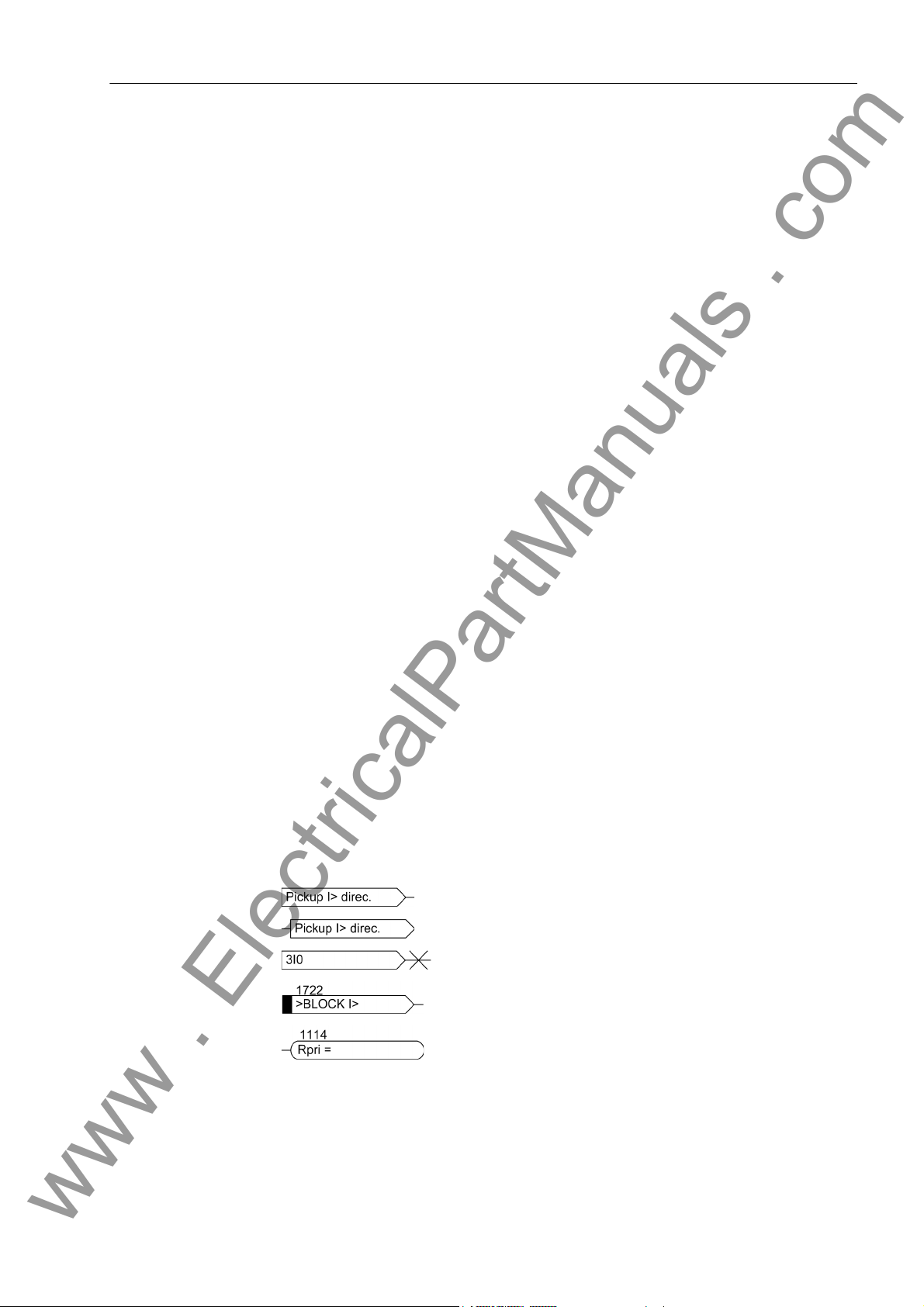
The following symbols are used in drawings:
Device-internal logical input signal
Device-internal (logical) output signal
Internal input signal of an analog quantity
External binary input signal with number (binary input, input
indication)
External binary output signal with number (device indication)
5
Preface
www . ElectricalPartManuals . com
External binary output signal with number (de vice indication)
used as input signal
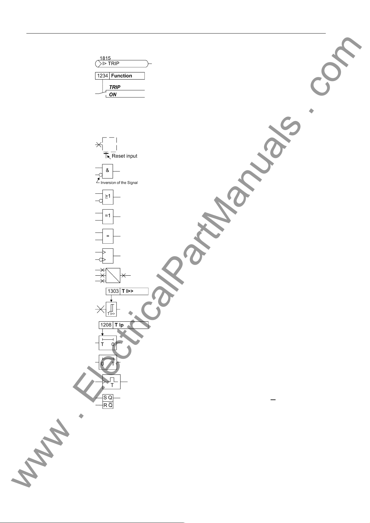
Example of a parameter switch designated FUNCTION with
the address 1234 and the possible settings ON and OFF
Besides these, graphical symbols are used according to IEC 60617-12 and IEC
60617-13 or symbols derived from these st andards. Some of the most frequently used
are listed below:
Input signal of an analog quantity
AND gate
OR gate
Exclusive OR (antivalence): output is active, if only one of
the inputs is active
Coincidence gate (equivalence): output is active if both
inputs are active or inactive at the same time
Dynamic inputs (edge–triggered) above with positive, below
with negative edge
Formation of one analog output signal from a number of
analog input signals
Limit stage with setting address and parameter designator
(name)
Timer (pickup delay T, example adjustable) with setting
address and parameter designator (name)
Timer (dropout delay T, example non-adjustable)
Dynamic triggered pulse timer T (monoflop)
Static memory (RS-flipflop) with setting input (S), resetting
input (R), output (Q) and inverted output (Q
■
6
)
7SD610 Manual
C53000-G1176-C145-4

Contents
www . ElectricalPartManuals . com
1 Introduction. . . . . . . . . . . . . . . . . . . . . . . . . . . . . . . . . . . . . . . . . . . . . . . . . . . . . . . . . . . . . . . . . . . . 15
1.1 Overall Operation . . . . . . . . . . . . . . . . . . . . . . . . . . . . . . . . . . . . . . . . . . . . . . . . . . . . . . . . 16
1.2 Application Scope . . . . . . . . . . . . . . . . . . . . . . . . . . . . . . . . . . . . . . . . . . . . . . . . . . . . . . . . 19
1.3 Characteristics. . . . . . . . . . . . . . . . . . . . . . . . . . . . . . . . . . . . . . . . . . . . . . . . . . . . . . . . . . . 22
2 Functions. . . . . . . . . . . . . . . . . . . . . . . . . . . . . . . . . . . . . . . . . . . . . . . . . . . . . . . . . . . . . . . . . . . . . . 27
2.1 General . . . . . . . . . . . . . . . . . . . . . . . . . . . . . . . . . . . . . . . . . . . . . . . . . . . . . . . . . . . . . . . . 28
2.1.1 Functional Scope. . . . . . . . . . . . . . . . . . . . . . . . . . . . . . . . . . . . . . . . . . . . . . . . . . . . . . . . . 28
2.1.1.1 Configuration of the Scope of Functions . . . . . . . . . . . . . . . . . . . . . . . . . . . . . . . . . . . . . . . 28
2.1.1.2 Setting Notes. . . . . . . . . . . . . . . . . . . . . . . . . . . . . . . . . . . . . . . . . . . . . . . . . . . . . . . . . . . . 29
2.1.1.3 Settings . . . . . . . . . . . . . . . . . . . . . . . . . . . . . . . . . . . . . . . . . . . . . . . . . . . . . . . . . . . . . . . . 31
2.1.2 General Power System Data (Power System Data 1). . . . . . . . . . . . . . . . . . . . . . . . . . . . . 32
2.1.2.1 Setting Notes. . . . . . . . . . . . . . . . . . . . . . . . . . . . . . . . . . . . . . . . . . . . . . . . . . . . . . . . . . . . 32
2.1.2.2 Settings . . . . . . . . . . . . . . . . . . . . . . . . . . . . . . . . . . . . . . . . . . . . . . . . . . . . . . . . . . . . . . . . 38
2.1.3 Change Group. . . . . . . . . . . . . . . . . . . . . . . . . . . . . . . . . . . . . . . . . . . . . . . . . . . . . . . . . . . 39
2.1.3.1 Purpose of the Setting Groups . . . . . . . . . . . . . . . . . . . . . . . . . . . . . . . . . . . . . . . . . . . . . . 39
2.1.3.2 Setting Notes. . . . . . . . . . . . . . . . . . . . . . . . . . . . . . . . . . . . . . . . . . . . . . . . . . . . . . . . . . . . 39
2.1.3.3 Settings . . . . . . . . . . . . . . . . . . . . . . . . . . . . . . . . . . . . . . . . . . . . . . . . . . . . . . . . . . . . . . . . 40
2.1.3.4 Information List . . . . . . . . . . . . . . . . . . . . . . . . . . . . . . . . . . . . . . . . . . . . . . . . . . . . . . . . . . 40
2.1.4 General Protection Data (Power System Data 2) . . . . . . . . . . . . . . . . . . . . . . . . . . . . . . . . 40
2.1.4.1 Setting Notes. . . . . . . . . . . . . . . . . . . . . . . . . . . . . . . . . . . . . . . . . . . . . . . . . . . . . . . . . . . . 40
2.1.4.2 Settings . . . . . . . . . . . . . . . . . . . . . . . . . . . . . . . . . . . . . . . . . . . . . . . . . . . . . . . . . . . . . . . . 46
2.1.4.3 Information List . . . . . . . . . . . . . . . . . . . . . . . . . . . . . . . . . . . . . . . . . . . . . . . . . . . . . . . . . . 47
2.2 Protection Data Interfaces and Protectio n Data Topology. . . . . . . . . . . . . . . . . . . . . . . . . . 49
2.2.1 Functional Description. . . . . . . . . . . . . . . . . . . . . . . . . . . . . . . . . . . . . . . . . . . . . . . . . . . . . 49
2.2.1.1 Protection Data Topology / Protection Data Communication. . . . . . . . . . . . . . . . . . . . . . . . 49
2.2.2 Operating Modes of the Differential Protection . . . . . . . . . . . . . . . . . . . . . . . . . . . . . . . . . . 51
2.2.2.1 Mode: Log Out Device. . . . . . . . . . . . . . . . . . . . . . . . . . . . . . . . . . . . . . . . . . . . . . . . . . . . . 51
2.2.2.2 Differential Protection Test Mode. . . . . . . . . . . . . . . . . . . . . . . . . . . . . . . . . . . . . . . . . . . . . 53
2.2.2.3 Differential Protection Commissioning Mode. . . . . . . . . . . . . . . . . . . . . . . . . . . . . . . . . . . . 55
2.2.3 Protection Data Interfaces. . . . . . . . . . . . . . . . . . . . . . . . . . . . . . . . . . . . . . . . . . . . . . . . . . 56
2.2.3.1 Setting Notes. . . . . . . . . . . . . . . . . . . . . . . . . . . . . . . . . . . . . . . . . . . . . . . . . . . . . . . . . . . . 56
2.2.3.2 Settings . . . . . . . . . . . . . . . . . . . . . . . . . . . . . . . . . . . . . . . . . . . . . . . . . . . . . . . . . . . . . . . . 58
2.2.3.3 Information List . . . . . . . . . . . . . . . . . . . . . . . . . . . . . . . . . . . . . . . . . . . . . . . . . . . . . . . . . . 59
2.2.4 Differential Protection Topology. . . . . . . . . . . . . . . . . . . . . . . . . . . . . . . . . . . . . . . . . . . . . . 59
2.2.4.1 Setting Notes. . . . . . . . . . . . . . . . . . . . . . . . . . . . . . . . . . . . . . . . . . . . . . . . . . . . . . . . . . . . 59
2.2.4.2 Settings . . . . . . . . . . . . . . . . . . . . . . . . . . . . . . . . . . . . . . . . . . . . . . . . . . . . . . . . . . . . . . . . 61
2.2.4.3 Information List . . . . . . . . . . . . . . . . . . . . . . . . . . . . . . . . . . . . . . . . . . . . . . . . . . . . . . . . . . 61
77SD610 Manual
C53000-G1176-C145-4

Contents
www . ElectricalPartManuals . com
2.3 Differential Protection . . . . . . . . . . . . . . . . . . . . . . . . . . . . . . . . . . . . . . . . . . . . . . . . . . . . . 62
2.3.1 Function Description . . . . . . . . . . . . . . . . . . . . . . . . . . . . . . . . . . . . . . . . . . . . . . . . . . . . . . 62
2.3.2 Setting Notes. . . . . . . . . . . . . . . . . . . . . . . . . . . . . . . . . . . . . . . . . . . . . . . . . . . . . . . . . . . . 70
2.3.3 Settings . . . . . . . . . . . . . . . . . . . . . . . . . . . . . . . . . . . . . . . . . . . . . . . . . . . . . . . . . . . . . . . . 73
2.3.4 Information List . . . . . . . . . . . . . . . . . . . . . . . . . . . . . . . . . . . . . . . . . . . . . . . . . . . . . . . . . . 74
2.4 Breaker Intertrip and Remote Tripping . . . . . . . . . . . . . . . . . . . . . . . . . . . . . . . . . . . . . . . . 76
2.4.1 Function Description . . . . . . . . . . . . . . . . . . . . . . . . . . . . . . . . . . . . . . . . . . . . . . . . . . . . . . 76
2.4.2 Setting Notes. . . . . . . . . . . . . . . . . . . . . . . . . . . . . . . . . . . . . . . . . . . . . . . . . . . . . . . . . . . . 77
2.4.3 Settings . . . . . . . . . . . . . . . . . . . . . . . . . . . . . . . . . . . . . . . . . . . . . . . . . . . . . . . . . . . . . . . . 78
2.4.4 Information List . . . . . . . . . . . . . . . . . . . . . . . . . . . . . . . . . . . . . . . . . . . . . . . . . . . . . . . . . . 78
2.5 Restricted Earth Fault Protection (optional). . . . . . . . . . . . . . . . . . . . . . . . . . . . . . . . . . . . . 80
2.5.1 Application Examples . . . . . . . . . . . . . . . . . . . . . . . . . . . . . . . . . . . . . . . . . . . . . . . . . . . . . 80
2.5.2 Functional Description. . . . . . . . . . . . . . . . . . . . . . . . . . . . . . . . . . . . . . . . . . . . . . . . . . . . . 81
2.5.3 Setting Notes. . . . . . . . . . . . . . . . . . . . . . . . . . . . . . . . . . . . . . . . . . . . . . . . . . . . . . . . . . . . 86
2.5.4 Settings . . . . . . . . . . . . . . . . . . . . . . . . . . . . . . . . . . . . . . . . . . . . . . . . . . . . . . . . . . . . . . . . 87
2.5.5 Information List . . . . . . . . . . . . . . . . . . . . . . . . . . . . . . . . . . . . . . . . . . . . . . . . . . . . . . . . . . 88
2.6 Direct Local Trip. . . . . . . . . . . . . . . . . . . . . . . . . . . . . . . . . . . . . . . . . . . . . . . . . . . . . . . . . . 89
2.6.1 Method of Operation . . . . . . . . . . . . . . . . . . . . . . . . . . . . . . . . . . . . . . . . . . . . . . . . . . . . . . 89
2.6.2 Setting Notes. . . . . . . . . . . . . . . . . . . . . . . . . . . . . . . . . . . . . . . . . . . . . . . . . . . . . . . . . . . . 89
2.6.3 Settings . . . . . . . . . . . . . . . . . . . . . . . . . . . . . . . . . . . . . . . . . . . . . . . . . . . . . . . . . . . . . . . . 90
2.6.4 Information List . . . . . . . . . . . . . . . . . . . . . . . . . . . . . . . . . . . . . . . . . . . . . . . . . . . . . . . . . . 90
2.7 Direct Remote Trip and Transmission of Binary Information. . . . . . . . . . . . . . . . . . . . . . . . 91
2.7.1 Function Description . . . . . . . . . . . . . . . . . . . . . . . . . . . . . . . . . . . . . . . . . . . . . . . . . . . . . . 91
2.7.2 Information List . . . . . . . . . . . . . . . . . . . . . . . . . . . . . . . . . . . . . . . . . . . . . . . . . . . . . . . . . . 92
2.8 Instantaneous High-Current Switch-onto-Fault Protection (SOTF) . . . . . . . . . . . . . . . . . . . 93
2.8.1 Function Description . . . . . . . . . . . . . . . . . . . . . . . . . . . . . . . . . . . . . . . . . . . . . . . . . . . . . . 93
2.8.2 Setting Notes. . . . . . . . . . . . . . . . . . . . . . . . . . . . . . . . . . . . . . . . . . . . . . . . . . . . . . . . . . . . 94
2.8.3 Settings . . . . . . . . . . . . . . . . . . . . . . . . . . . . . . . . . . . . . . . . . . . . . . . . . . . . . . . . . . . . . . . . 95
2.8.4 Information List . . . . . . . . . . . . . . . . . . . . . . . . . . . . . . . . . . . . . . . . . . . . . . . . . . . . . . . . . . 96
2.9 Backup Time Overcurrent Protection. . . . . . . . . . . . . . . . . . . . . . . . . . . . . . . . . . . . . . . . . . 97
2.9.1 General . . . . . . . . . . . . . . . . . . . . . . . . . . . . . . . . . . . . . . . . . . . . . . . . . . . . . . . . . . . . . . . . 97
2.9.2 Function Description . . . . . . . . . . . . . . . . . . . . . . . . . . . . . . . . . . . . . . . . . . . . . . . . . . . . . . 97
2.9.3 Setting Notes. . . . . . . . . . . . . . . . . . . . . . . . . . . . . . . . . . . . . . . . . . . . . . . . . . . . . . . . . . . .111
2.9.4 Settings . . . . . . . . . . . . . . . . . . . . . . . . . . . . . . . . . . . . . . . . . . . . . . . . . . . . . . . . . . . . . . . 117
2.9.5 Information List . . . . . . . . . . . . . . . . . . . . . . . . . . . . . . . . . . . . . . . . . . . . . . . . . . . . . . . . . 120
2.10 Automatic Reclosure Function (optional). . . . . . . . . . . . . . . . . . . . . . . . . . . . . . . . . . . . . . 122
2.10.1 Function Description . . . . . . . . . . . . . . . . . . . . . . . . . . . . . . . . . . . . . . . . . . . . . . . . . . . . . 122
2.10.2 Setting Notes. . . . . . . . . . . . . . . . . . . . . . . . . . . . . . . . . . . . . . . . . . . . . . . . . . . . . . . . . . . 138
2.10.3 Settings . . . . . . . . . . . . . . . . . . . . . . . . . . . . . . . . . . . . . . . . . . . . . . . . . . . . . . . . . . . . . . . 146
2.10.4 Information List . . . . . . . . . . . . . . . . . . . . . . . . . . . . . . . . . . . . . . . . . . . . . . . . . . . . . . . . . 149
8
7SD610 Manual
C53000-G1176-C145-4

Contents
www . ElectricalPartManuals . com
2.11 Undervoltage and Overvoltage Protection (optional). . . . . . . . . . . . . . . . . . . . . . . . . . . . . 151
2.11.1 Overvoltage protection . . . . . . . . . . . . . . . . . . . . . . . . . . . . . . . . . . . . . . . . . . . . . . . . . . . 151
2.11.2 Undervoltage protection . . . . . . . . . . . . . . . . . . . . . . . . . . . . . . . . . . . . . . . . . . . . . . . . . . 158
2.11.3 Setting Notes. . . . . . . . . . . . . . . . . . . . . . . . . . . . . . . . . . . . . . . . . . . . . . . . . . . . . . . . . . . 161
2.11.4 Settings . . . . . . . . . . . . . . . . . . . . . . . . . . . . . . . . . . . . . . . . . . . . . . . . . . . . . . . . . . . . . . . 166
2.11.5 Information List . . . . . . . . . . . . . . . . . . . . . . . . . . . . . . . . . . . . . . . . . . . . . . . . . . . . . . . . . 168
2.12 Frequency Protection (optional) . . . . . . . . . . . . . . . . . . . . . . . . . . . . . . . . . . . . . . . . . . . . 171
2.12.1 Functional Description. . . . . . . . . . . . . . . . . . . . . . . . . . . . . . . . . . . . . . . . . . . . . . . . . . . . 171
2.12.2 Setting Notes. . . . . . . . . . . . . . . . . . . . . . . . . . . . . . . . . . . . . . . . . . . . . . . . . . . . . . . . . . . 173
2.12.3 Settings . . . . . . . . . . . . . . . . . . . . . . . . . . . . . . . . . . . . . . . . . . . . . . . . . . . . . . . . . . . . . . . 175
2.12.4 Information List . . . . . . . . . . . . . . . . . . . . . . . . . . . . . . . . . . . . . . . . . . . . . . . . . . . . . . . . . 176
2.13 Circuit Breaker Failure Protection . . . . . . . . . . . . . . . . . . . . . . . . . . . . . . . . . . . . . . . . . . . 177
2.13.1 Function Description . . . . . . . . . . . . . . . . . . . . . . . . . . . . . . . . . . . . . . . . . . . . . . . . . . . . . 177
2.13.2 Setting Notes. . . . . . . . . . . . . . . . . . . . . . . . . . . . . . . . . . . . . . . . . . . . . . . . . . . . . . . . . . . 188
2.13.3 Settings . . . . . . . . . . . . . . . . . . . . . . . . . . . . . . . . . . . . . . . . . . . . . . . . . . . . . . . . . . . . . . . 192
2.13.4 Information List . . . . . . . . . . . . . . . . . . . . . . . . . . . . . . . . . . . . . . . . . . . . . . . . . . . . . . . . . 193
2.14 Thermal Overload Protection. . . . . . . . . . . . . . . . . . . . . . . . . . . . . . . . . . . . . . . . . . . . . . . 194
2.14.1 Method of Operation . . . . . . . . . . . . . . . . . . . . . . . . . . . . . . . . . . . . . . . . . . . . . . . . . . . . . 194
2.14.2 Setting Notes. . . . . . . . . . . . . . . . . . . . . . . . . . . . . . . . . . . . . . . . . . . . . . . . . . . . . . . . . . . 195
2.14.3 Settings . . . . . . . . . . . . . . . . . . . . . . . . . . . . . . . . . . . . . . . . . . . . . . . . . . . . . . . . . . . . . . . 197
2.14.4 Information List . . . . . . . . . . . . . . . . . . . . . . . . . . . . . . . . . . . . . . . . . . . . . . . . . . . . . . . . . 197
2.15 Monitoring Functions. . . . . . . . . . . . . . . . . . . . . . . . . . . . . . . . . . . . . . . . . . . . . . . . . . . . . 198
2.15.1 Measurement Supervision. . . . . . . . . . . . . . . . . . . . . . . . . . . . . . . . . . . . . . . . . . . . . . . . . 198
2.15.1.1 Hardware Monitoring. . . . . . . . . . . . . . . . . . . . . . . . . . . . . . . . . . . . . . . . . . . . . . . . . . . . . 198
2.15.1.2 Software Monitoring. . . . . . . . . . . . . . . . . . . . . . . . . . . . . . . . . . . . . . . . . . . . . . . . . . . . . . 200
2.15.1.3 Measurement Circuit Monitoring . . . . . . . . . . . . . . . . . . . . . . . . . . . . . . . . . . . . . . . . . . . . 200
2.15.1.4 Monitoring the Phase Angle of the Positive Sequence Power . . . . . . . . . . . . . . . . . . . . . 207
2.15.1.5 Fault Reactions . . . . . . . . . . . . . . . . . . . . . . . . . . . . . . . . . . . . . . . . . . . . . . . . . . . . . . . . . 210
2.15.1.6 Setting Notes. . . . . . . . . . . . . . . . . . . . . . . . . . . . . . . . . . . . . . . . . . . . . . . . . . . . . . . . . . . 212
2.15.1.7 Settings . . . . . . . . . . . . . . . . . . . . . . . . . . . . . . . . . . . . . . . . . . . . . . . . . . . . . . . . . . . . . . . 213
2.15.1.8 Information List . . . . . . . . . . . . . . . . . . . . . . . . . . . . . . . . . . . . . . . . . . . . . . . . . . . . . . . . . 214
2.15.2 Trip Circuit Supervision . . . . . . . . . . . . . . . . . . . . . . . . . . . . . . . . . . . . . . . . . . . . . . . . . . . 215
2.15.2.1 Function Description . . . . . . . . . . . . . . . . . . . . . . . . . . . . . . . . . . . . . . . . . . . . . . . . . . . . . 215
2.15.2.2 Setting Notes. . . . . . . . . . . . . . . . . . . . . . . . . . . . . . . . . . . . . . . . . . . . . . . . . . . . . . . . . . . 219
2.15.2.3 Settings . . . . . . . . . . . . . . . . . . . . . . . . . . . . . . . . . . . . . . . . . . . . . . . . . . . . . . . . . . . . . . . 219
2.15.2.4 Information List . . . . . . . . . . . . . . . . . . . . . . . . . . . . . . . . . . . . . . . . . . . . . . . . . . . . . . . . . 219
7SD610 Manual
C53000-G1176-C145-4
9

Contents
www . ElectricalPartManuals . com
2.16 Function Control and Circuit Breaker Test. . . . . . . . . . . . . . . . . . . . . . . . . . . . . . . . . . . . . 220
2.16.1 Function Control . . . . . . . . . . . . . . . . . . . . . . . . . . . . . . . . . . . . . . . . . . . . . . . . . . . . . . . . 220
2.16.1.1 Line energisation recognition. . . . . . . . . . . . . . . . . . . . . . . . . . . . . . . . . . . . . . . . . . . . . . . 220
2.16.1.2 Detection of the Circuit Breaker Position. . . . . . . . . . . . . . . . . . . . . . . . . . . . . . . . . . . . . . 224
2.16.1.3 Open Pole Detector. . . . . . . . . . . . . . . . . . . . . . . . . . . . . . . . . . . . . . . . . . . . . . . . . . . . . . 226
2.16.1.4 Pickup Logic of the Entire Device . . . . . . . . . . . . . . . . . . . . . . . . . . . . . . . . . . . . . . . . . . . 228
2.16.1.5 Tripping Logic of the Entire Device . . . . . . . . . . . . . . . . . . . . . . . . . . . . . . . . . . . . . . . . . . 229
2.16.2 Circuit Breaker Test . . . . . . . . . . . . . . . . . . . . . . . . . . . . . . . . . . . . . . . . . . . . . . . . . . . . . . 234
2.16.2.1 Functional Description. . . . . . . . . . . . . . . . . . . . . . . . . . . . . . . . . . . . . . . . . . . . . . . . . . . . 234
2.16.2.2 Information List . . . . . . . . . . . . . . . . . . . . . . . . . . . . . . . . . . . . . . . . . . . . . . . . . . . . . . . . . 235
2.16.3 Device . . . . . . . . . . . . . . . . . . . . . . . . . . . . . . . . . . . . . . . . . . . . . . . . . . . . . . . . . . . . . . . . 235
2.16.3.1 Trip-Dependent Indications . . . . . . . . . . . . . . . . . . . . . . . . . . . . . . . . . . . . . . . . . . . . . . . . 236
2.16.3.2 Spontaneous Indications on the Display . . . . . . . . . . . . . . . . . . . . . . . . . . . . . . . . . . . . . . 236
2.16.3.3 Switching Statistics . . . . . . . . . . . . . . . . . . . . . . . . . . . . . . . . . . . . . . . . . . . . . . . . . . . . . . 236
2.16.3.4 Setting Notes. . . . . . . . . . . . . . . . . . . . . . . . . . . . . . . . . . . . . . . . . . . . . . . . . . . . . . . . . . . 237
2.16.3.5 Settings . . . . . . . . . . . . . . . . . . . . . . . . . . . . . . . . . . . . . . . . . . . . . . . . . . . . . . . . . . . . . . . 237
2.16.3.6 Information List . . . . . . . . . . . . . . . . . . . . . . . . . . . . . . . . . . . . . . . . . . . . . . . . . . . . . . . . . 237
2.16.4 EN100-Modul 1 . . . . . . . . . . . . . . . . . . . . . . . . . . . . . . . . . . . . . . . . . . . . . . . . . . . . . . . . . 239
2.16.4.1 Function Description . . . . . . . . . . . . . . . . . . . . . . . . . . . . . . . . . . . . . . . . . . . . . . . . . . . . . 239
2.16.4.2 Setting Notes. . . . . . . . . . . . . . . . . . . . . . . . . . . . . . . . . . . . . . . . . . . . . . . . . . . . . . . . . . . 239
2.16.4.3 Information List . . . . . . . . . . . . . . . . . . . . . . . . . . . . . . . . . . . . . . . . . . . . . . . . . . . . . . . . . 239
2.17 Additional Functions . . . . . . . . . . . . . . . . . . . . . . . . . . . . . . . . . . . . . . . . . . . . . . . . . . . . . 240
2.17.1 Commissioning aid . . . . . . . . . . . . . . . . . . . . . . . . . . . . . . . . . . . . . . . . . . . . . . . . . . . . . . 240
2.17.1.1 Function Description . . . . . . . . . . . . . . . . . . . . . . . . . . . . . . . . . . . . . . . . . . . . . . . . . . . . . 240
2.17.1.2 Setting Notes. . . . . . . . . . . . . . . . . . . . . . . . . . . . . . . . . . . . . . . . . . . . . . . . . . . . . . . . . . . 242
2.17.2 Processing of Messages . . . . . . . . . . . . . . . . . . . . . . . . . . . . . . . . . . . . . . . . . . . . . . . . . . 242
2.17.2.1 Function Description . . . . . . . . . . . . . . . . . . . . . . . . . . . . . . . . . . . . . . . . . . . . . . . . . . . . . 242
2.17.3 Statistics. . . . . . . . . . . . . . . . . . . . . . . . . . . . . . . . . . . . . . . . . . . . . . . . . . . . . . . . . . . . . . . 246
2.17.3.1 Function Description . . . . . . . . . . . . . . . . . . . . . . . . . . . . . . . . . . . . . . . . . . . . . . . . . . . . . 246
2.17.3.2 Information List . . . . . . . . . . . . . . . . . . . . . . . . . . . . . . . . . . . . . . . . . . . . . . . . . . . . . . . . . 247
2.17.4 Measurement During Operation . . . . . . . . . . . . . . . . . . . . . . . . . . . . . . . . . . . . . . . . . . . . 247
2.17.4.1 Function Description . . . . . . . . . . . . . . . . . . . . . . . . . . . . . . . . . . . . . . . . . . . . . . . . . . . . . 247
2.17.4.2 Information List . . . . . . . . . . . . . . . . . . . . . . . . . . . . . . . . . . . . . . . . . . . . . . . . . . . . . . . . . 249
2.17.5 Differential Protection Values. . . . . . . . . . . . . . . . . . . . . . . . . . . . . . . . . . . . . . . . . . . . . . . 250
2.17.5.1 Measured values of the differential protection. . . . . . . . . . . . . . . . . . . . . . . . . . . . . . . . . . 250
2.17.5.2 Information List . . . . . . . . . . . . . . . . . . . . . . . . . . . . . . . . . . . . . . . . . . . . . . . . . . . . . . . . . 251
2.17.6 Remote Measured Values . . . . . . . . . . . . . . . . . . . . . . . . . . . . . . . . . . . . . . . . . . . . . . . . . 251
2.17.6.1 Function Description . . . . . . . . . . . . . . . . . . . . . . . . . . . . . . . . . . . . . . . . . . . . . . . . . . . . . 251
2.17.7 Measured values constellation . . . . . . . . . . . . . . . . . . . . . . . . . . . . . . . . . . . . . . . . . . . . . 252
2.17.7.1 Functional Description. . . . . . . . . . . . . . . . . . . . . . . . . . . . . . . . . . . . . . . . . . . . . . . . . . . . 252
2.17.8 Oscillographic Fault Records. . . . . . . . . . . . . . . . . . . . . . . . . . . . . . . . . . . . . . . . . . . . . . . 252
2.17.8.1 Function Description . . . . . . . . . . . . . . . . . . . . . . . . . . . . . . . . . . . . . . . . . . . . . . . . . . . . . 252
2.17.8.2 Setting Notes. . . . . . . . . . . . . . . . . . . . . . . . . . . . . . . . . . . . . . . . . . . . . . . . . . . . . . . . . . . 253
2.17.8.3 Settings . . . . . . . . . . . . . . . . . . . . . . . . . . . . . . . . . . . . . . . . . . . . . . . . . . . . . . . . . . . . . . . 254
2.17.8.4 Information List . . . . . . . . . . . . . . . . . . . . . . . . . . . . . . . . . . . . . . . . . . . . . . . . . . . . . . . . . 254
2.17.9 Energy . . . . . . . . . . . . . . . . . . . . . . . . . . . . . . . . . . . . . . . . . . . . . . . . . . . . . . . . . . . . . . . . 254
2.17.9.1 Energy Metering . . . . . . . . . . . . . . . . . . . . . . . . . . . . . . . . . . . . . . . . . . . . . . . . . . . . . . . . 254
2.17.9.2 Setting Notes. . . . . . . . . . . . . . . . . . . . . . . . . . . . . . . . . . . . . . . . . . . . . . . . . . . . . . . . . . . 255
2.17.9.3 Information List . . . . . . . . . . . . . . . . . . . . . . . . . . . . . . . . . . . . . . . . . . . . . . . . . . . . . . . . . 255
10
7SD610 Manual
C53000-G1176-C145-4

Contents
www . ElectricalPartManuals . com
2.18 Command Processing . . . . . . . . . . . . . . . . . . . . . . . . . . . . . . . . . . . . . . . . . . . . . . . . . . . 256
2.18.1 Control Authorization. . . . . . . . . . . . . . . . . . . . . . . . . . . . . . . . . . . . . . . . . . . . . . . . . . . . . 256
2.18.1.1 Type of Commands . . . . . . . . . . . . . . . . . . . . . . . . . . . . . . . . . . . . . . . . . . . . . . . . . . . . . 256
2.18.1.2 Sequence in the Command Path . . . . . . . . . . . . . . . . . . . . . . . . . . . . . . . . . . . . . . . . . . . 257
2.18.1.3 Interlocking . . . . . . . . . . . . . . . . . . . . . . . . . . . . . . . . . . . . . . . . . . . . . . . . . . . . . . . . . . . 258
2.18.1.4 Information List . . . . . . . . . . . . . . . . . . . . . . . . . . . . . . . . . . . . . . . . . . . . . . . . . . . . . . . . . 261
2.18.2 Control Device. . . . . . . . . . . . . . . . . . . . . . . . . . . . . . . . . . . . . . . . . . . . . . . . . . . . . . . . . . 261
2.18.2.1 Information List . . . . . . . . . . . . . . . . . . . . . . . . . . . . . . . . . . . . . . . . . . . . . . . . . . . . . . . . . 261
2.18.3 Process Data. . . . . . . . . . . . . . . . . . . . . . . . . . . . . . . . . . . . . . . . . . . . . . . . . . . . . . . . . . . 262
2.18.3.1 Method of Operation . . . . . . . . . . . . . . . . . . . . . . . . . . . . . . . . . . . . . . . . . . . . . . . . . . . . . 262
2.18.3.2 Information List . . . . . . . . . . . . . . . . . . . . . . . . . . . . . . . . . . . . . . . . . . . . . . . . . . . . . . . . . 263
2.18.4 Protocol . . . . . . . . . . . . . . . . . . . . . . . . . . . . . . . . . . . . . . . . . . . . . . . . . . . . . . . . . . . . . . . 263
2.18.4.1 Information List . . . . . . . . . . . . . . . . . . . . . . . . . . . . . . . . . . . . . . . . . . . . . . . . . . . . . . . . . 263
3 Mounting and Commissioning . . . . . . . . . . . . . . . . . . . . . . . . . . . . . . . . . . . . . . . . . . . . . . . . . . . 265
3.1 Mounting and Connections . . . . . . . . . . . . . . . . . . . . . . . . . . . . . . . . . . . . . . . . . . . . . . . . 266
3.1.1 Configuration Information . . . . . . . . . . . . . . . . . . . . . . . . . . . . . . . . . . . . . . . . . . . . . . . . . 266
3.1.2 Hardware Modifications. . . . . . . . . . . . . . . . . . . . . . . . . . . . . . . . . . . . . . . . . . . . . . . . . . . 270
3.1.2.1 General . . . . . . . . . . . . . . . . . . . . . . . . . . . . . . . . . . . . . . . . . . . . . . . . . . . . . . . . . . . . . . . 270
3.1.2.2 Disassembly . . . . . . . . . . . . . . . . . . . . . . . . . . . . . . . . . . . . . . . . . . . . . . . . . . . . . . . . . . . 271
3.1.2.3 Switching Elements on Printed Circuit Boards . . . . . . . . . . . . . . . . . . . . . . . . . . . . . . . . . 273
3.1.2.4 Interface Modules . . . . . . . . . . . . . . . . . . . . . . . . . . . . . . . . . . . . . . . . . . . . . . . . . . . . . . . 279
3.1.2.5 Reassembly. . . . . . . . . . . . . . . . . . . . . . . . . . . . . . . . . . . . . . . . . . . . . . . . . . . . . . . . . . . . 283
3.1.3 Mounting . . . . . . . . . . . . . . . . . . . . . . . . . . . . . . . . . . . . . . . . . . . . . . . . . . . . . . . . . . . . . . 283
3.1.3.1 Panel Flush Mounting . . . . . . . . . . . . . . . . . . . . . . . . . . . . . . . . . . . . . . . . . . . . . . . . . . . . 283
3.1.3.2 Rack and Cubicle Mounting . . . . . . . . . . . . . . . . . . . . . . . . . . . . . . . . . . . . . . . . . . . . . . . 284
3.1.3.3 Panel Mounting . . . . . . . . . . . . . . . . . . . . . . . . . . . . . . . . . . . . . . . . . . . . . . . . . . . . . . . . . 285
3.2 Checking Connections. . . . . . . . . . . . . . . . . . . . . . . . . . . . . . . . . . . . . . . . . . . . . . . . . . . . 286
3.2.1 Checking Data Connections of Serial Interfaces. . . . . . . . . . . . . . . . . . . . . . . . . . . . . . . . 286
3.2.2 Checking the Protection Data Communication . . . . . . . . . . . . . . . . . . . . . . . . . . . . . . . . . 288
3.2.3 Checking the System Connections . . . . . . . . . . . . . . . . . . . . . . . . . . . . . . . . . . . . . . . . . . 289
3.3 Commissioning . . . . . . . . . . . . . . . . . . . . . . . . . . . . . . . . . . . . . . . . . . . . . . . . . . . . . . . . . 292
3.3.1 Test Mode / Transmission Block . . . . . . . . . . . . . . . . . . . . . . . . . . . . . . . . . . . . . . . . . . . . 293
3.3.2 Test Time Synchronisation Interface . . . . . . . . . . . . . . . . . . . . . . . . . . . . . . . . . . . . . . . . . 293
3.3.3 Testing the System Interface. . . . . . . . . . . . . . . . . . . . . . . . . . . . . . . . . . . . . . . . . . . . . . . 294
3.3.4 Checking the switching states of the binary Inputs/Outputs . . . . . . . . . . . . . . . . . . . . . . . 296
3.3.5 Checking the Protection Data Topology . . . . . . . . . . . . . . . . . . . . . . . . . . . . . . . . . . . . . . 298
3.3.6 Checking for Breaker Failure Protection . . . . . . . . . . . . . . . . . . . . . . . . . . . . . . . . . . . . . . 305
3.3.7 Checking the Instrument Transformer Connections of One Line End. . . . . . . . . . . . . . . . 307
3.3.8 Checking the Instrument Transformer Connections of Two Line Ends . . . . . . . . . . . . . . . 309
3.3.9 Check of the Signal Transmission for Internal and External Remote Tripping . . . . . . . . . 315
3.3.10 Testing User-defined Functions. . . . . . . . . . . . . . . . . . . . . . . . . . . . . . . . . . . . . . . . . . . . . 316
3.3.11 Trip and Close Test with the Circuit Breaker . . . . . . . . . . . . . . . . . . . . . . . . . . . . . . . . . . . 316
3.3.12 Trip / Close Tests for the Configured Operating Devices. . . . . . . . . . . . . . . . . . . . . . . . . . 316
3.3.13 Triggering Oscillographic Recording for Test. . . . . . . . . . . . . . . . . . . . . . . . . . . . . . . . . . . 317
3.4 Final Preparation of the Device . . . . . . . . . . . . . . . . . . . . . . . . . . . . . . . . . . . . . . . . . . . . 318
7SD610 Manual
C53000-G1176-C145-4
11

Contents
www . ElectricalPartManuals . com
4 Technical Data. . . . . . . . . . . . . . . . . . . . . . . . . . . . . . . . . . . . . . . . . . . . . . . . . . . . . . . . . . . . . . . . . 319
4.1 General . . . . . . . . . . . . . . . . . . . . . . . . . . . . . . . . . . . . . . . . . . . . . . . . . . . . . . . . . . . . . . . 320
4.1.1 Analog Inputs. . . . . . . . . . . . . . . . . . . . . . . . . . . . . . . . . . . . . . . . . . . . . . . . . . . . . . . . . . . 320
4.1.2 Auxiliary voltage. . . . . . . . . . . . . . . . . . . . . . . . . . . . . . . . . . . . . . . . . . . . . . . . . . . . . . . . . 321
4.1.3 Binary Inputs and Outputs . . . . . . . . . . . . . . . . . . . . . . . . . . . . . . . . . . . . . . . . . . . . . . . . 322
4.1.4 Communication Interfaces . . . . . . . . . . . . . . . . . . . . . . . . . . . . . . . . . . . . . . . . . . . . . . . . 323
4.1.5 Electrical Tests . . . . . . . . . . . . . . . . . . . . . . . . . . . . . . . . . . . . . . . . . . . . . . . . . . . . . . . . . 327
4.1.6 Mechanical Tests. . . . . . . . . . . . . . . . . . . . . . . . . . . . . . . . . . . . . . . . . . . . . . . . . . . . . . . . 328
4.1.7 Climatic stress tests. . . . . . . . . . . . . . . . . . . . . . . . . . . . . . . . . . . . . . . . . . . . . . . . . . . . . . 329
4.1.8 Deployment Conditions . . . . . . . . . . . . . . . . . . . . . . . . . . . . . . . . . . . . . . . . . . . . . . . . . . . 330
4.1.9 Constructive versions . . . . . . . . . . . . . . . . . . . . . . . . . . . . . . . . . . . . . . . . . . . . . . . . . . . . 330
4.2 Protection Data Interfaces and differential protection topology. . . . . . . . . . . . . . . . . . . . . 331
4.3 Differential Protection . . . . . . . . . . . . . . . . . . . . . . . . . . . . . . . . . . . . . . . . . . . . . . . . . . . . 333
4.4 Restricted Earth Fault Protection. . . . . . . . . . . . . . . . . . . . . . . . . . . . . . . . . . . . . . . . . . . . 335
4.5 Breaker Intertrip and Remote Tripping- Dire ct Local Trip . . . . . . . . . . . . . . . . . . . . . . . . . 336
4.6 Transmission of Binary Information (optional). . . . . . . . . . . . . . . . . . . . . . . . . . . . . . . . . . 337
4.7 Instantaneous High-Current Switch-onto-Fault Protection (SOTF) . . . . . . . . . . . . . . . . . . 338
4.8 Backup Time Overcurrent Protection. . . . . . . . . . . . . . . . . . . . . . . . . . . . . . . . . . . . . . . . . 339
4.9 Automatic Reclosure (optional) . . . . . . . . . . . . . . . . . . . . . . . . . . . . . . . . . . . . . . . . . . . . . 346
4.10 Voltage Protection (optional) . . . . . . . . . . . . . . . . . . . . . . . . . . . . . . . . . . . . . . . . . . . . . . . 347
4.11 Frequency Protection (optional). . . . . . . . . . . . . . . . . . . . . . . . . . . . . . . . . . . . . . . . . . . . . 350
4.12 Circuit Breaker Failure Protection (optional) . . . . . . . . . . . . . . . . . . . . . . . . . . . . . . . . . . . 351
4.13 Thermal Overload Protection. . . . . . . . . . . . . . . . . . . . . . . . . . . . . . . . . . . . . . . . . . . . . . . 352
4.14 Monitoring Functions . . . . . . . . . . . . . . . . . . . . . . . . . . . . . . . . . . . . . . . . . . . . . . . . . . . . . 354
4.15 User defined functions (CFC) . . . . . . . . . . . . . . . . . . . . . . . . . . . . . . . . . . . . . . . . . . . . . . 356
4.16 Auxiliary functions . . . . . . . . . . . . . . . . . . . . . . . . . . . . . . . . . . . . . . . . . . . . . . . . . . . . . . . 360
4.17 Dimensions . . . . . . . . . . . . . . . . . . . . . . . . . . . . . . . . . . . . . . . . . . . . . . . . . . . . . . . . . . . . 363
4.17.1 Housing for Panel Flush Mounting or Cubicle Installation. . . . . . . . . . . . . . . . . . . . . . . . . 363
4.17.2 Panel Surface Mounting . . . . . . . . . . . . . . . . . . . . . . . . . . . . . . . . . . . . . . . . . . . . . . . . . . 364
A Appendix . . . . . . . . . . . . . . . . . . . . . . . . . . . . . . . . . . . . . . . . . . . . . . . . . . . . . . . . . . . . . . . . . . . . . 365
A.1 Ordering Information and Accessories . . . . . . . . . . . . . . . . . . . . . . . . . . . . . . . . . . . . . . . 366
A.1.1 Ordering Information . . . . . . . . . . . . . . . . . . . . . . . . . . . . . . . . . . . . . . . . . . . . . . . . . . . . . 366
A.1.1.1 Ordering Code (MLFB) . . . . . . . . . . . . . . . . . . . . . . . . . . . . . . . . . . . . . . . . . . . . . . . . . . . 366
A.1.2 Accessories . . . . . . . . . . . . . . . . . . . . . . . . . . . . . . . . . . . . . . . . . . . . . . . . . . . . . . . . . . . . 368
12
7SD610 Manual
C53000-G1176-C145-4

Contents
www . ElectricalPartManuals . com
A.2 Terminal Assignments . . . . . . . . . . . . . . . . . . . . . . . . . . . . . . . . . . . . . . . . . . . . . . . . . . . . 372
A.2.1 Housing for Panel Flush and Cubicle Mounting . . . . . . . . . . . . . . . . . . . . . . . . . . . . . . . . 372
A.2.2 Housing for panel surface mounting . . . . . . . . . . . . . . . . . . . . . . . . . . . . . . . . . . . . . . . . . 373
A.3 Connection Examples . . . . . . . . . . . . . . . . . . . . . . . . . . . . . . . . . . . . . . . . . . . . . . . . . . . . 374
A.3.1 Current Transformer Connection Examples . . . . . . . . . . . . . . . . . . . . . . . . . . . . . . . . . . . 374
A.3.2 Voltage Transformer Examples. . . . . . . . . . . . . . . . . . . . . . . . . . . . . . . . . . . . . . . . . . . . . 376
A.4 Default Settings. . . . . . . . . . . . . . . . . . . . . . . . . . . . . . . . . . . . . . . . . . . . . . . . . . . . . . . . . 377
A.4.1 LEDs . . . . . . . . . . . . . . . . . . . . . . . . . . . . . . . . . . . . . . . . . . . . . . . . . . . . . . . . . . . . . . . . . 377
A.4.2 Binary Input . . . . . . . . . . . . . . . . . . . . . . . . . . . . . . . . . . . . . . . . . . . . . . . . . . . . . . . . . . . . 377
A.4.3 Binary Output . . . . . . . . . . . . . . . . . . . . . . . . . . . . . . . . . . . . . . . . . . . . . . . . . . . . . . . . . . 378
A.4.4 Function Keys . . . . . . . . . . . . . . . . . . . . . . . . . . . . . . . . . . . . . . . . . . . . . . . . . . . . . . . . . . 378
A.4.5 Default Display . . . . . . . . . . . . . . . . . . . . . . . . . . . . . . . . . . . . . . . . . . . . . . . . . . . . . . . . . 378
A.4.6 Pre-defined CFC Charts . . . . . . . . . . . . . . . . . . . . . . . . . . . . . . . . . . . . . . . . . . . . . . . . . . 379
A.5 Protocol-dependent Functions. . . . . . . . . . . . . . . . . . . . . . . . . . . . . . . . . . . . . . . . . . . . . . 380
A.6 Functional Scope. . . . . . . . . . . . . . . . . . . . . . . . . . . . . . . . . . . . . . . . . . . . . . . . . . . . . . . . 381
A.7 Settings . . . . . . . . . . . . . . . . . . . . . . . . . . . . . . . . . . . . . . . . . . . . . . . . . . . . . . . . . . . . . . . 382
A.8 Information List . . . . . . . . . . . . . . . . . . . . . . . . . . . . . . . . . . . . . . . . . . . . . . . . . . . . . . . . . 392
A.9 Group Alarms . . . . . . . . . . . . . . . . . . . . . . . . . . . . . . . . . . . . . . . . . . . . . . . . . . . . . . . . . . 416
A.10 Measured Values. . . . . . . . . . . . . . . . . . . . . . . . . . . . . . . . . . . . . . . . . . . . . . . . . . . . . . . . 417
Literature. . . . . . . . . . . . . . . . . . . . . . . . . . . . . . . . . . . . . . . . . . . . . . . . . . . . . . . . . . . . . . . . . . . . . 421
Glossary . . . . . . . . . . . . . . . . . . . . . . . . . . . . . . . . . . . . . . . . . . . . . . . . . . . . . . . . . . . . . . . . . . . . . 423
Index . . . . . . . . . . . . . . . . . . . . . . . . . . . . . . . . . . . . . . . . . . . . . . . . . . . . . . . . . . . . . . . . . . . . . . . . 433
7SD610 Manual
C53000-G1176-C145-4
13

Contents
www . ElectricalPartManuals . com
14
7SD610 Manual
C53000-G1176-C145-4

Introduction 1
www . ElectricalPartManuals . com
The SIPROTEC 4 7SD610 is introduced in this chapter. The device is presented in its
application, characteristics, and functional scope.
1.1 Overall Operation 16
1.2 Application Scope 19
1.3 Characteristics 22
157SD610 Manual
C53000-G1176-C145-4
1 Introduction
www . ElectricalPartManuals . com
1.1 Overall Operation
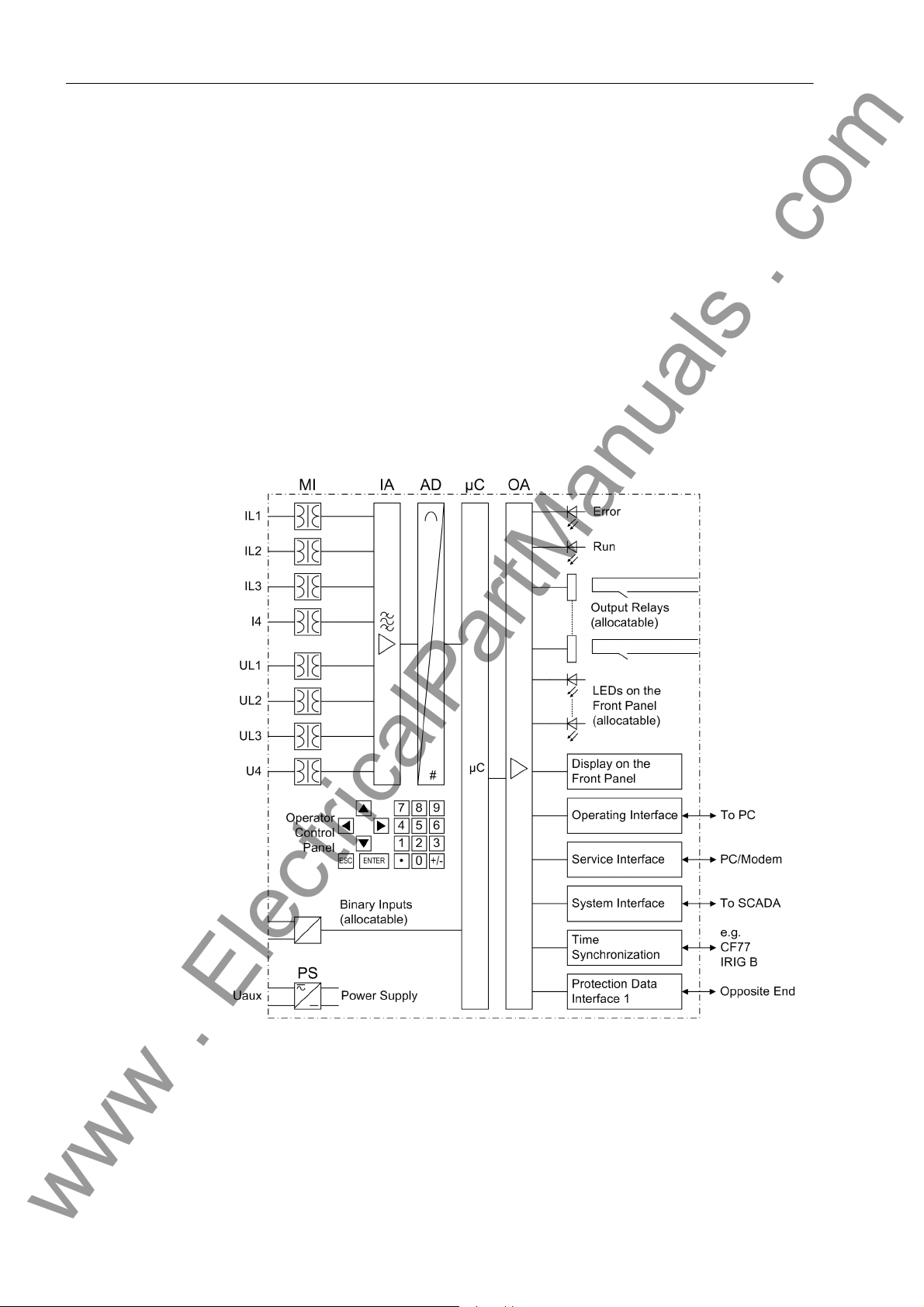
The SIPROTEC 4 7SD610 line protection is equipped with a powerful microprocessor
system. This provides fully numerical processing of all functions in the device, from th e
acquisition of the measured values up to the output of commands to the circuit breakers, as well as the exchange of measured data with the other ends of the protected
area. Figure 1-1 shows the basic structure of the device.
Analog Inputs The measuring inputs (MI) convert the currents and voltages coming from the instru-
ment transformers and adapt them to the level appropriate for the in ternal processing
of the device. The device has 4 current and 4 volt age inputs . Three current inp uts are
provided for measurement of the phase currents, a further measuring input (I
be used for the residual current (current transformer starpoint or a separate earth
current transformer) or the starpoint current of the transformer side to be protected by
the restricted earth fault protection.
) may
4
Figure 1-1 Hardware structure of the differential protection 7SD610
16
7SD610 Manual
C53000-G1176-C145-4

1.1 Overall Operation
www . ElectricalPartManuals . com
A voltage measuring input is provided for each phase-earth voltage. In principle, the
differential protection does not require any measured voltage, however, for the directed overcurrent time protection the connection of the phase earth voltages U
is definitely required. Additionally voltages that allow to measure voltages and
U
L3
powers and voltages that enable the user to measure the line voltage also for automatic reclosure can be switched to the device. A further voltage input (U
ally be used to measure the displacement voltage (e–n–volt age) or for any voltage U
(for overcurrent protection). The analog values are transferred further to the IA input
amplifier group.
The input amplifier group IA provides high-resistance termina tion for the analog input
quantities. It consists of filters that are optimized for measured value p ro ces sing with
regard to bandwidth and processing speed.
The AD analog digital converter group contains analog/digital converters and memory
components for data transfer to the microcomputer system.
, UL2 and
L1
) may option-
4
x
Microcomputer System
Binary Inputs and Outputs
Apart from processing the measured values, the microcomputer system µC also executes the actual protection and control functions. They especially consist of:
• Filtering and conditioning of the measured signals
• Continuous monitoring of the measured quantities
• Monitoring of the pickup conditions for the individual protective functions
• Formation of the local differential protection values (phasor analysis and charge
current computation) and creation of the transmissi on protocol
• Decoding of the received transmission protocol, synchronisation of the differential
protection values and summing up of the differential currents and charge currents
• Monitoring the communication with the device of the remote end
• Querying of limit values and time sequences
• Control of signals for logical functions
• Reaching trip and close command decisions
• Stocking message s, fault data and fault values for fault analysis purposes
• Administration of the operating system and its functions, e .g. data storage, realtime
clock, communication, interfaces, etc.
The information is provided via output amplifier OA.
Binary inputs and outputs from and to th e computer system are routed via the I/O
modules (inputs and outputs). The “µC” issues information to external equipment via
the output contacts. Outputs are mainly commands that are issued to the switching
devices and messages for remote signalling of events and states.
Front Elements LEDs and an LC display provide information on the function of the device and indicate
events, states and measured values.
Integrated control and numeric keys in conjunction with the LCD facilitate local inter-
action with the local device. All information of the device can be accessed using the
integrated control and numeric keys. This information includes protective and control
settings, operating and fault indications, and measured value s; setting parameters can
be changed (see also Chapter 2 and SIPROTEC 4 System Description).
Devices with control functions also allow station control on the front panel.
7SD610 Manual
C53000-G1176-C145-4
17

1 Introduction
www . ElectricalPartManuals . com
Serial Interfaces Via the serial operator interface in the front panel the communication with a personal
computer using the operating program DIGSI is possible. This facilitates a comfortable
handling of all device functions.
The service interface
using DIGSI. This is especially well suited for the central interrogation of the devices
from a PC or for remote operation via a modem.
All device data can be transmitted to a central evaluating unit or control center through
the serial system (SCADA) interface
physical transmission modes and different protocols to suit the particular application.
A further interface is provided for time synchronization
ternal synchronization sources.
Further communication protocols can be realized via additional interface modules.
The operating or service interfaces allow the communication with bo th devices during
commissioning, checking and also during ope ra tio n of th e de vice , via a commu nication network using a standard browser . For this a special tool, the WEB-Monitor , is provided, which has been optimized for differential protection.
Protection Data Interface
Power Supply These described functional units are supplied by a power supply PS with the neces-
The protection data interface is a particular case. It is used to transfer the
measuring data from each end of the protection area to the opposite end. Further information such as closing the local circuit breaker, pickup of the inrush restraint as well
as other external trip commands coupled via binary inputs or binary information can
be transmitted to the other end via the protectio n da ta interfac e .
sary power in the different voltage levels. Brief supply voltage dips which may occur
on short circuits in the auxiliary voltage supply of the power system are usually bridged
by a capacitor (see also Technical Data, Sub-section 4.1).
can also be used for communication with a personal computer
. This interface may be provided with various
of the internal clock through ex-
18
7SD610 Manual
C53000-G1176-C145-4

1.2 Application Scope
www . ElectricalPartManuals . com
The numerical Differential Prot ection SIPROTEC 4 7SD610 is a selective short-circuit
protection for overhead lines and cables with single- and multi-en ded infeeds in radial,
ring or any type of meshed systems of any transmission level. Conditioning of the
system starpoint is irrelevant, as measuring data are compared separately for each
phase.
High sensitivity and the inrush current restraint allow for the application of the 7SD610,
even if a power transformer is located within the protected zone (ordering option)
whose starpoint(s) might also be isolated, earthed or provided with a Petersen coil.
A major advantage of the differential protection principle is the inst an tan eous tripping
in the event of a short-circuit at any point within the entire protected zone. The current
transformers limit the protected zone at the ends towards the remaining system. This
rigid delimitation is the reason why the differential protection scheme shows such an
ideal selectivity.
The differential protection system requ ires a 7SD610 device as well as a set of current
transformers at either end of the pro tected zone. Voltage transformers are not required. However , they are available for indicating and processing of me asured values
(voltages, power, power factor), or when using a directional overcurrent protection
stage (ordering variant).
1.2 Application Scope
Protection Functions
The devices located at the ends of the protected zone exchange measuring information via protection data interfaces using dedicated communication links (usually fibreoptic cables) or a communication network. Using 7SD610 a protected obje ct with two
ends can be protected: cable, overhead line or both , even with uni t-conn ected powe r
transformer (option). For each end a 7SD610 is used.
Since fault-free data transmission is the prerequisite for the proper operation of the
protection, it is continuously monitored internally.
Recognition of short circuits in the protection zone — even of weak-current or highresistive shorting — is the basic function of the device. Even complex multiphase
faults are precisely detected, as the measured values are evalua ted phase segregated. The protection system is restrained against inrush currents of power transformers.
Subsequent to energizing the line onto a fault which may be located along the entire
line length, it is possible to achieve a non-delayed trip signal.
In the event of a communication failure, the devices can automatica lly be switched to
emergency operation using an integrated time overcurrent protection until communication is restored again. This overcurrent protection has three current-independent
stages and one current-dependen t stage. Furthermore, the device has a directional
current-independent stage and a di rectional current-independent stage which ena bles
an increased selectivity of the emergency function. For inverse time overcurrent protection stages, several curves of diff erent standards are provided.
Alternatively, the time overcurrent protection can be used as a backup time overcurrent protection, i.e. it operates independent of and para llel to the differential protection
at either end.
The communication connection can be used for transmitting further information.
Besides measured values, binary commands or other information can be transmitted
as well (ordering variant).
Depending on the order variant, the short-circuit protection functions may also trip
single-pole, and may operate in co-operation with an integrated automatic reclosure
(optionally). The automatic reclose function may be used on overhead lin es for single-
7SD610 Manual
C53000-G1176-C145-4
19

1 Introduction
www . ElectricalPartManuals . com
pole, three-pole or single- and three-pole automatic reclosure as well as multi-shot automatic reclosure.
Apart from the short-circuit protection functions mentioned, a thermal overload protection has been integrated which protects in particular cables and power transformers
from undue heating through overload. Furthe rmore, multi-step over and undervolta ge
as well as frequency protection and restricted earth fault protection can be used (ordering variant). An optional circuit breaker failure protection provides rapid backup
fault clearance instruction to the adjacent circuit breakers in case the local breaker
fails to respond.
Control Functions The device is equipped with control functions which operate, close and open, switch-
gear via the integrated operator panel, the system interface, binary inputs, and using
a personal computer with DIGSI software. Using auxiliary contacts of the switch and
binary inputs of the device, switching states feedbacks are issued. The current status
(or position) of the primary equipment can be read out at the device, and used for interlocking or plausibility monitoring. The number of the devices to be switched is
limited by the binary inputs and output s available in the device or the binary inputs and
outputs allocated for the switch position feedbacks. Depending on the resource one
(single point indication) or two binary inputs ( double point indication) can be used. The
capability of switching primary equipment can be restricted by appropriate settings for
the switching authority (remote or local), and by the oper ating m ode (i nterlocked/noninterlocked, with or without password request). Interlocking conditions for switching
(e.g. switchgear interlocking) can be established using the integrated user-defined
logic.
Indications and Measured Values; Fault Recording
Communication Serial interfaces are available for the communication with operating, control and
The operational indications provide information about cond itions in the power system
and the device. Measurement quantities and values that are calculated can be displayed locally and communicated via the serial interfaces.
Indications can be assigned to a number of LEDs on the front p anel (allocatable) , can
be externally processed via output contacts (allocatable), linked with user-definable
logic functions and/or issued via serial interfaces (see Communication below).
During a fault (power system fault) important events and changes in conditions are
saved in fault logs (Event Log or Trip Log). Instantaneous fault values are also saved
in the device and may be analyzed subsequently.
As a special feature the values are synchronized between the line terminals via the
communication link.
memory systems.
A 9-pin DSUB socket on the front panel is used for local communication with a person-
al computer. By means of the SIPROTEC 4 operating software DIGSI all operational
and evaluation tasks can be executed via this operator
and modifying configuration parameters and settings, configuring user-specific logic
functions, retrieving operational messages, fault re cords and measured values, inquiring device conditions and measured values, issuing control commands.
To establish an extensive communication with other digital operating, control and
memory components the device may be p rovided with further interfaces depending on
the order variant.
interface, such as specifying
The service
allows communication via modem. For this reason, remote operation is possible via
20
interface can be operated via the RS232 or RS485 interface and also
7SD610 Manual
C53000-G1176-C145-4

1.2 Application Scope
www . ElectricalPartManuals . com
personal computer and the DIGSI operating sof tware, e.g. to oper ate several devices
via a central PC.
The system
control centre. It can be operated through the RS232, RS485 or FO port. For data
transmission there are several standardized protocols available. An EN100 module
allows to integrate the devices into the 100 MBit Ethernet communication networks of
the process control and automation systems using IEC 61850 protocols. In parallel to
the link with the process control and automation system, this interface can also handle
DIGSI communication and inter-relay communication using GOOSE.
Another interface is provided for the time synchronization
ternal synchronization sources (IRIG-B or DCF77).
Other interfaces provide for communication between the devices at the ends of the
protected object. These protection data
protection functions.
The operator or service interface allows to operate the device remotely or locally. This
is possible during commissioning, checking and also during operation with the devices
at all ends of the protected object via a communication network. For this a special tool,
the „WEB-Monitor“, is provided, which has been optimized for differential protection.
interface is used for central communication between the device and a
of the internal clock via ex-
interfaces have been mentioned above in the
7SD610 Manual
C53000-G1176-C145-4
21

1 Introduction
www . ElectricalPartManuals . com
1.3 Characteristics
General Features • Powerful 32-bit microprocessor system
• Complete digital processing of measured values and contro l, fr om the samplin g of
the analog input values, the processing and organization of the communication
between devices up to the closing and tripping commands to the circuit breakers
• complete galvanic and reliable separation be tween the internal processing circuits
from the measurement, control, and power supply circuits by analogue input transducers, binary inputs and outputs and the DC/DC or AC voltage converters
• Suited for lines with 2 ends, even with transformers in the protected zone (order
option)
• simple device operation using the integrated operator p anel or a connected personal computer with operator guidance
• storage of fault messages as well as instantaneous values for fault recording
Differential
Protection
• Differential protection system for 2 ends with digital protection data transmission
• Protection for all types of short-circuits in systems with any starpoint conditioning
• Reliable differentiation between load and fault conditions also in high-resistant,
current-weak faults by adaptive measuring procedures
• High sensitivity in case of weakly loaded system, extreme stability against load
jumps and power swings
• Phase segregated measurement ensures that the pickup sensitivity is independent
of the fault type
• Suited for transformers in the protected zone (order varian t)
• Detection of high-resistant, weak-current faults due to high sensitivity of th e protective functions
• Insensitive against inrush and charging currents – also for transformers in the protected zone – and against higher-frequency switching transients
• High stability also for different current transformer saturation
• Adaptive stabilisation that is automatically derived from the measured quantities
and the configured current transformer data
• Fast, phase segregated tripping also on weak or zero infeed ends (breaker intertrip)
• low frequency dependency
• Digital protection data tran smission; communication between devices via dedicated
communication links (in general optical fibre) or a communication system
• Communication possible via a single copper wire pair (typically 15 km, max. 30 km,
depending on used cable type)
• Synchronization via GPS possible. resulting in automatic correction of transmission
time differences thus increasing once more the se nsitivity
• Permanent monitoring of the protection da t a transmission concerning disturbance,
failure or transfer time deviations in the transmission networ k with a utomatic tr an sfer time correction
• Phase segregated tripping possible (for operation with single-pole or single-and
three-pole auto-reclosure) (order variant)
22
7SD610 Manual
C53000-G1176-C145-4

1.3 Characteristics
www . ElectricalPartManuals . com
Restricted Earth Fault Protection
External Direct and Remote Tripping
Trans m ission of
Information
Time Overcurrent Protection
• Earth fault protection for earthed transformer windings
• Short tripping time
• High sensitivity for earth faults
• High stability against external earth faults using the magnitude and phase relationship of through-flowing earth current
• tripping of the local end by an external device via binary input
• Tripping of the remote end by internal protection functions or by an external device
via binary input
• Transmission of measured values from the other end of the protected object.
• Transmission of up to 4 fast commands to all remote ends (optional)
• Selectable as emergency function during protection d ata communication failure or
as back-up function or as both
• Maximally two definite time stages and one inverse time stage each for phase currents and earth current
• Two directional definite time stages (DT) and one directional inverse time stage
(IDMT), each for phase currents and earth current
High Current Switch-onto-Fault Protection
Automatic
Reclosure Function
(optional)
• for inverse time overcurrent protection a selection from various characteristics
based on several standards is possible
• Blocking capability e.g. for reverse interlocking with any element
• Instantaneous tripping by any stage when switching onto a fault
• Fast tripping for all faults on 100 % line length
• Selectable for manual closure or following each closure of the circuit breaker
• With integrated line energization detection.
• For reclosure after single-pole, three-pole or single-pole and three-pole tripping
• Single or multiple reclosure (up to 8 reclosure attempts)
• With separate action times for every reclosure attempt, optionally without action
times
• With separate dead times after single-p ole and three-pole tripping, sep arate for the
first four reclosure attempts
• With the option of an adaptive dead time: in this case the one device controls the
automatic reclosure cycles whilst at the other line end the automatic reclosure
solely depends on the one controlling device. The criteria used are voltage measurement and/or the transmitted CLOSE command (Remote-CLOSE)
• Automatic reclosure controlled optionally by protection start with separate dead
times after single, two and three-pole starting
7SD610 Manual
C53000-G1176-C145-4
23

1 Introduction
www . ElectricalPartManuals . com
Voltage Protection (optional)
Frequency
Protection
(optional)
• Overvoltage and undervoltage detection with different stages
• Two overvoltage stages for the phase-earth voltages
• Two overvoltage stages for the phase-phase voltages
• Two overvoltage stages for the positive sequence voltage, optionally with compounding
• Two overvoltage stages for the negative sequence voltage
• Two overvoltage stages for the zero sequence voltage or any other single-phase
voltage
• Settable drop-off to pi ck-up ratios
• Two undervoltage stages for the phase-earth volt ages
• Two undervoltage stages for the phase-phase voltages
• Two undervoltage stages for the positive sequence voltage
• Settable current criterion for undervoltage protection functions
• Monitoring on underfrequency (f<) and/or ov erfrequency (f>) with 4 frequency limit s
and delay times that are independently adjustable
• Very insensitive to harmonics and abrupt phase angle changes
• Large frequency range (approx. 25 Hz to 70 Hz)
Circuit Breaker Failure Protection (optional)
Thermal Overload Protection
User-defined Logic Functions (CFC)
• Definite time stages for monitoring current flow through every pole of the circuit
breaker
• Separate pickup thresholds for phase and earth currents
• Independent timers for single-pole and three-pole tripping;
• Start by trip command of every internal protection function
• Start by external trip functions possible
• Single-stage or two-stage
• Short dropout and overshoot times
• End fault protection and pole discrepancy monitoring possible
• Thermal replica of the current heat losses of the protected object
• R.M.S. measurement of all three phase currents
• Settable thermal and current-dependent warning stages
• Freely programmable combination of internal and external signals for the implementation of user-defined logic functions
• All usual logic functions
• Time delays and limit value inquiries
24
7SD610 Manual
C53000-G1176-C145-4

1.3 Characteristics
www . ElectricalPartManuals . com
Commissioning; Operation; Maintenance
Command Processing
Monitoring Functions
• Display of magnitude and phase angle of local and remote measured values
• Indication of the calculated differential and restraint cu rr en ts
• Display of measured values of the communication link, such as transmission delay
and availability
• Switchgear can be switched on and off manually via local control keys, the pr ogrammable function keys on the front panel, via the system interface (e.g. by SICAM or
LSA), or via the operator interface (using a personal computer and the operating
software DIGSI)
• Feedback on switching states via the circuit breaker auxiliary contacts (for commands with feedback)
• Plausibility monitoring of the circuit breaker position and monitoring of interlocking
conditions for switching operations
• Availability of the device is greatly increased because of self-monitoring of the internal measurement circuits, power supply, hardware and software
• Monitoring of the current and voltage tran sformer secondary circuits by means of
summation and symmetry checks
• Monitoring of communication with statistics showing the availability of transmission
telegrams
• Check of the consistency of protection settings at both line ends: no processor
system start-up with inconsistent settings which could lead to a malfunction of the
differential protection system
• Trip circuit supervision
• Check of local and remote measured values and comparison of both
• Broken wire supervision for the secondary CT circuits with fast phase segregated
blocking of the differential protection system in order to avoid malfunction
• Supervision of measuring voltage failure using "Fuse Failure Mon itor"
Further Functions • Battery buffered real-time clock, which may be synchron ized via a synchr onization
signal (e.g. DCF77, IRIG B, GPS via satellite receiver), binary input or system interface
• Automatic time synchronization between the devices at the ends of the protected
object via the protection data transmission
• Continuous calculation and display of measured quantities on the front of the
device. Indication of measured quantities of the remote end
• Fault event memory (trip log) for the last 8 network faults (faults in the power system), with real time stamps
• Fault recording memory and data transfer for analog and user configurable binary
signal traces with a maximum time range of 15 s, synchronized between the
devices of the differential protection system
• Switching statistics: Counter with the trip commands issued by the device, as well
as record of the short-circuit current dat a and accumulation of the interrupted shortcircuit currents
• Communication with central control and data storag e e quip ment via seria l inter faces through the choice of RS232, RS485, modem, or optical fibres, as an option
7SD610 Manual
C53000-G1176-C145-4
25

1 Introduction
www . ElectricalPartManuals . com
• Commissioning aids such as connection and direction checks as well as circuit
breaker test functions
• The WEB-Monitor (installed on a PC or a laptop) widely supports the testing and
commissioning procedure. The communication topology of the differential protection and communication system, phasor diagrams of all current s and (if app licable)
voltages at both ends of the differential system are displayed as a graph
■
26
7SD610 Manual
C53000-G1176-C145-4

Functions 2
www . ElectricalPartManuals . com
This chapter describes the individual functions of the SIPROTEC 4 device 7SD610. It
shows the setting possibilities for each function in maximum configuration. Guidelines
for establishing setting values and, where required, formulae are given.
Additionally, on the basis of the following information, it may be defined which functions are to be used.
2.1 General 28
2.2 Protection Data Interfaces and Protection Data Topology 49
2.3 Differential Protection 62
2.4 Breaker Intertrip and Remote T ripping 76
2.5 Restricted Earth Fault Protection (optional) 80
2.6 Direct Local Trip 89
2.7 Direct Remote Trip and Transmission of Binary Information 91
2.8 Instantaneous High-Current Switch-onto-Fault Protection (SOTF) 93
2.9 Backup Time Overcurrent Protection 97
2.10 Automatic Reclosure Function (optional) 122
2.11 Undervoltage and Overvoltage Protection (optional) 151
2.12 Frequency Protection (optional) 171
2.13 Circuit Breaker Failure Protection 177
2.14 Thermal Overload Protection 194
2.15 Monitoring Functions 198
2.16 Function Control and Circuit Breaker Test 220
2.17 Additional Functions 240
2.18 Command Processing 256
277SD610 Manual
C53000-G1176-C145-4

2 Functions
www . ElectricalPartManuals . com
2.1 General
A few seconds after the device is switched on, the default display appears on the LCD.
In the 7SD610 the measured values are displayed.
Configuration settings can be entered by using a PC and the DIGSI operating software
and transferred via the operator interface on the front panel of the device or via the
service interface. The procedure is described in detail in the SIPROTEC 4 System Description. Entry of password no. 7 (parameter set) is required to modif y config ur at ion
settings. Without the password, the settings may be read, but may not be modifi ed and
transmitted to the device.
The function parameters, i.e. function options, threshold values, etc., can be changed
via the front panel of the device, or via the operator or service interfa ce from a personal
computer using DIGSI. The level 5 password (individual parameters) is required.
This general section describes which device settings reflect the interaction between
your substation, its measuring points (current and voltage transformers), the analog
device connections and the various protective functions of the device.
In a first step (Subsection 2.1.1), you have to specify which protection functions you
want to use, because not all of the functions integrated in the device are necessary,
useful or even possible for your relevant case of app lica tio n.
After entering some System Data (frequency) , you inform the device (Section 2.1.2) of
the properties of the main protected object. This com prises e.g. nominal system dat a,
nominal data of instrument transformers, polarity and connectio n type of measured
values
The above information is sufficient to describe the protected object to the device's
main protection function, i.e. the differential protection. Fo r the other protection functions (e.g. overcurrent time protection) you select what measured values will be processed and in which way.
You will be informed how to set the circuit breaker data, and find out about setting
groups and how to use them.
Last but not least, you can set general data which are not dep endent on any protection
functions.
2.1.1 Functional Scope
2.1.1.1 Configuration of the Scope of Functions
The 7SD610 device contains a series of protective and additional fun ctions. The hard-
ware and firmware is designed for this scope of functions. In addition, the command
functions can be matched to the system conditions. In addition, individual functions
may be enabled or disabled during configuration, or inter action between functions may
be adjusted.
Example
7SD610 - devices can be used on overhead lines ev en with tra n s fo rm ers in the pro-
tected area. Overload protection should only be applied on transformers. If the device
is used for overhead lines this function has to be set "Disabled" and if used for transformers this function has to be set "Enabled".
28
for the configuration of scope of functions:
7SD610 Manual
C53000-G1176-C145-4

2.1.1.2 Setting Notes
www . ElectricalPartManuals . com
2.1 General
The available protection and supplement ary functions can be configured as Enabled
or Disabled. For some functions, a choice may be presented between several
options which are explained below.
Functions configured as Disabled are not processed by the 7SD610. There are no
indications, and corresponding settin gs (functions, limit values) are not displayed
during setting.
Note
The functions and default settings available depend o n the order variant of the de vice.
Configuring the functional scope
Special Ca ses If use of the setting group changeover function is desired, address 103 Grp Chge
The scope of functions with the available options is set in the Functional Scope dialog
box to match plant requirements.
Most settings are self-explaining. The special cases
OPTION should be set to Enabled. In this case, up to four different groups of settings
may be changed quickly and easily during device operation (see also Section 2.1.3).
With the setting Disabled only one parameter group is available.
Address 110 Trip mode is only valid for devices that can trip single-pole or threepole. Set 1-/3pole to enable also single-pole tripping, i.e. if you want to utilise singlepole or single-pole/three-pole automatic reclosure. This requires that an internal automatic reclosure function exists or that an external reclosing device is used. Furthermore, the circuit breaker must be capable of single-pole tripping.
Note
If you have changed address 110, save your changes first via OK and reopen the
dialog box since the other setting options depend on the selection in address 110.
The differential protection function DIFF.PROTECTION (address 112) as a main function of the device should always be Enabled. This also implies the supplementary
functions of the differential protection such as breaker intertrip.
are described below.
The Direct Local Trip (address 122 DTT Direct Trip) is a command that is initiated
from an external device for tripping the local circuit breaker.
At address 126 Back-Up O/C you can set the characteristic group which the time
overcurrent protection uses for operation. In addition to the definite-time overcurrent
protection (definite time) an inverse-time overcurrent protec tion can be configured that
either operates according to an IEC characteristic (TOC IEC) or to an ANSI characteristic (TOC ANSI). This selection is independent of whether the time overcurrent protection is intended to operate as emergency protection (onl y in case of protection communication failure) or as independent backup protection. Wit device variants with
directional time overcurrent protection (MLFB position 14 = R or S) you have an add itional directional definite-time overcurrent stage and a directional current dependent
inverse-time stage available to you. The characteristic curves for both inverse-time
7SD610 Manual
C53000-G1176-C145-4
29

2 Functions
www . ElectricalPartManuals . com
overcurrent stages are identical. The characteristics are shown in the Technical Data
(Section 4.6). You can also disable the time overcurrent protection (Disabled).
If the device features an automatic reclosing function, a ddress 133 and 134 are of importance. Automatic reclosure is only permitted for overhead lines. It must not be used
in any other case. If the protected object consists of a combination of overhead lines
and other equipment (e.g. overhead line in unit with a transformer or overhead line/cable), reclosure is only permissible if it can be ensured that it can only take place in the
event of a fault on the overhead line. If no automatic reclosing function is desired for
the feeder at which 7SD610 operates, or if an external device is used for reclosure,
set address 133 Auto Reclose to Disabled.
In the address mentioned the number of desired reclosure cycles is set. Y o u can select
1 AR-cycle to 8 AR-cycles. Yo u can also set ASP (adaptive dead times); in this
case the behaviour of the automatic reclosure function is determined by the cycles of
the remote end. However , at one end of the lin e the nu mber of cycles m ust be configured. This end must provide an infeed. The other end can then o perate with adaptive
dead time. See Subsection 2.10 for detailed information.
The AR control mode at address 134 allows a total of four options. On the one
hand, it can be determined whether the auto reclose cycles are carried out accord ing
to the fault type detected by the pickup of the starting protective function(s) (only for
three-pole tripping) or according to the type of trip command. On the o ther hand, the
automatic reclosure function can be operated with or without action time.
The setting Trip with T-action / Trip without T-action ... (default
setting = With trip command ... ) is to be preferred if single-pole
pole auto reclose cycles are provided for and possible. In this case, different dead
times (for every AR cycle) are possible after single-pole tripping and after three-pole
tripping. The protective function that issues the trip command determines the type of
trip: Single-pole or three-pole. The dead time is controlled dependent on this.
The setting Pickup with T-action / Pickup without T-action ...
(Pickup with T-action ...) is only possible and visible if only three-pole tripping is desired. This is the case when either the order ing number o f the device model indica tes
that it is only suited for three-pole tripping, or when only three-pole tripping is configured (address 110 Trip mode = 3pole only, see above). In this case you can set
different dead times for the auto reclose cycles following 1
cisive here is the pickup situation of the protection functions at the instant the trip
command disappears. This mode also enable s to make the dead ti mes dependent on
the type of fault in the case of three-pole reclosure cycles. The tripping is always threepole.
The setting Trip with T-action provides an action time for each reclose cycle.
The action time is started by a general pickup of all protective functions. If no trip
command is present before the action time expires, the corresponding reclose cycle
is not carried out. Section 2.10 provides detailed information on this top ic. This setting
is recommended for time-graded protection. If the protection function which is to
operate with automatic reclosure does not have a general pickup signal for st arting the
action times, select ... Trip without T-action.
or single-pole/three-
-, 2- and 3-phase faults. De-
Address 137 U/O VOLTAGE allows to activate the voltage protection function with a
variety of undervoltage and overvoltage protection stages. In particular, the overvoltage protection with the positive sequence syste m of the measuring volt ages provides
the option to calculate the voltage at the other, remote line end via integrated compounding. This is particularly useful for long transmission lines where no-load or lowload conditions prevail and an overvoltage at the other line end (Ferranti effect) is to
cause tripping of the local circuit breaker . In this case se t address 137 U/O VOLTAGE
30
7SD610 Manual
C53000-G1176-C145-4
 Loading...