

Siemens SIPROTEC 7SC805, SIPROTEC 6MU805 User Manual

SIPROTEC
Preface
Contents
Introduction 1
Functions 2
Merging Unit
7SC805
V4.50
Manual
Mounting and Commissioning 3
Technical Data 4
Appendix A
Literature
Glossary
Index
C53000-G1140-C380-1

Note
For safety purposes, please note instructions and warnings in the Preface.
Disclaimer of Liability
We have checked the contents of this manual against the hardware
and software described. However, deviations from the description
cannot be completely ruled out, so that no liability can be accepted
for any errors or omissions contained in the information given.
The information given in this document is reviewed regularly and
any necessary corrections will be included in subsequent editions.
Copyright
Copyright © Siemens AG 2014. All rights reserved.
Dissemination or reproduction of this document, or evaluation and
communication of its contents, is not authorized except where expressly permitted. Violations are liable for damages. All rights reserved, particularly for the purposes of patent application or trademark registration.
We appreciate any suggested improvements.
We reserve the right to make technical improvements without
notice.
Document version Release 4.00.00
Release date 05.2014
Registered Trademarks
SIPROTEC, SINAUT, SICAM and DIGSI are registered trademarks
of Siemens AG. Other designations in this manual might be trademarks whose use by third parties for their own purposes would infringe the rights of the owner.
Siemens Aktiengesellschaft Order no.: C53000-G1140-C380-1

Preface
Purpose of this Manual
This manual describes the functions, operation, installation, and commissioning of the Merging Unit device
7SC805. In particular, one will find:
• Information regarding the configuration of the scope of the device and a description of the device functions
and settings Chapter 2;
• Instructions for Installation and Commissioning Chapter 3;
• Compilation of the Technical Data Chapter 4;
• As well as a compilation of the most significant data for advanced users Appendix A.
T arget Audience
Protection engineers, commissioning engineers, personnel concerned with adjustment, checking, and service
of selective protective equipment, automatic and control facilities, and personnel of electrical facilities and
power plants.
Applicability of this Manual
This manual applies to: Merging Unit 7SC805; firmware version V4.50.
Indication of Conformity
This product complies with the directive of the Council of the European Communities on the
approximation of the laws of the Member States relating to electromagnetic compatibility (EMC
Council Directive 2004/108/EC) and concerning electrical equipment for use within specified
voltage limits (Low-voltage Directive 2006/95 EC).
This conformity is proved by tests conducted by Siemens AG in accordance with the Council
Directive in agreement with the generic standards EN 61000-6-2 and EN 61000-6-4 for EMC
directive, and with the standard EN 60255-27 for the low-voltage directive.
The device has been designed and produced for industrial use.
The product conforms with the international standards of the series IEC 60255 and the German
standard VDE 0435.
SIPROTEC, 7SC805, Manual
C53000-G1140-C380-1, Release date 05.2014
3

Preface
Additional St andards IEEE C37.90 (see Chapter 4 "Technical Data")
This product is UL-certified according to the Technical Data.
Additional Support
Should further information on the System SIPROTEC 4 be desired or should particular problems arise which
are not covered sufficiently for the purchaser's purpose, the matter should be referred to the local Siemens representative.
Our Customer Support Center provides a 24-hour service.
Phone: +49 (180) 524-8437
Fax: +49 (180) 524-2471
e-mail: support.ic@siemens.com
Training Courses
Enquiries regarding individual training courses should be addressed to our Training Center:
Siemens AG
Siemens Power Academy
Humboldt Street 59
90459 Nuremberg
Telephone: +49 (911) 433-7415
Fax: +49 (911) 433-5482
Internet: www.siemens.com/energy/power-academy
e-mail: poweracademy.ic-sg@siemens.com
4
C53000-G1140-C380-1, Release date 05.2014
SIPROTEC, 7SC805, Manual
Safety Information
This manual does not constitute a complete index of all required safety measures for operation of the equipment (module, device), as special operational conditions may require additional measures. However, it comprises important information that should be noted for purposes of personal safety as well as avoiding material
damage. Information that is highlighted by means of a warning triangle and according to the degree of danger,
is illustrated as follows.
DANGER!
Danger indicates that death, severe personal injury or substantial material damage will result if proper precautions are not taken.
WARNING!
indicates that death, severe personal injury or substantial property damage may result if proper precautions are
not taken.
Caution!
indicates that minor personal injury or property damage may result if proper precautions are not taken. This
particularly applies to damage to or within the device itself and consequential damage thereof.
Preface
Note
indicates information on the device, handling of the device, or the respective part of the instruction manual
which is important to be noted.
SIPROTEC, 7SC805, Manual
C53000-G1140-C380-1, Release date 05.2014
5

Preface
WARNING!
Qualified Personnel
Commissioning and operation of the equipment (module, device) as set out in this manual may only be carried
out by qualified personnel. Qualified personnel in terms of the technical safety information as set out in this
manual are persons who are authorized to commission, activate, to ground and to designate devices, systems
and electrical circuits in accordance with the safety standards.
Use as prescribed
The operational equipment (device, module) may only be used for such applications as set out in the catalog
and the technical description, and only in combination with third-party equipment recommended or approved
by Siemens.
The successful and safe operation of the device is dependent on proper handling, storage, installation, operation, and maintenance.
When operating an electrical equipment, certain parts of the device are inevitably subject to dangerous voltage.
Severe personal injury or property damage may result if the device is not handled properly.
Before any connections are made, the device must be grounded to the ground terminal.
All circuit components connected to the voltage supply may be subject to dangerous voltage.
Dangerous voltage may be present in the device even after the power supply voltage has been removed (capacitors can still be charged).
Operational equipment with exposed current transformer circuits may not be operated.
The limit values as specified in this manual or in the operating instructions may not be exceeded. This aspect
must also be observed during testing and commissioning.
6
C53000-G1140-C380-1, Release date 05.2014
SIPROTEC, 7SC805, Manual

T ypographic and Symbol Conventions
The following text formats are used when literal information from the device or to the device appear in the text
flow:
Parameter Names
Designators of configuration or function parameters which may appear word-for-word in the display of the
device or on the screen of a personal computer (with operation software DIGSI), are marked in bold letters in
monospace type style. The same goes for the titles of menus.
1234A
Parameter addresses have the same character style as parameter names. Parameter addresses contain the
suffix A in the overview tables if the parameter can only be set in DIGSI via the option Display additional set-
tings.
Parameter Options
Possible settings of text parameters, which may appear word-for-word in the display of the device or on the
screen of a personal computer (with operation software DIGSI), are additionally written in italics. This also
applies to header bars for selection menus.
“Messages”
Designators for information, which may be output by the relay or required from other devices or from the switch
gear, are marked in a monospace type style in quotation marks.
Preface
Deviations may be permitted in drawings and tables when the type of designator can be obviously derived from
the illustration.
■
SIPROTEC, 7SC805, Manual
C53000-G1140-C380-1, Release date 05.2014
7

Preface
8
C53000-G1140-C380-1, Release date 05.2014
SIPROTEC, 7SC805, Manual

Contents
1 Introduction. . . . . . . . . . . . . . . . . . . . . . . . . . . . . . . . . . . . . . . . . . . . . . . . . . . . . . . . . . . . . . . . . . . . . . . . . . . . . .13
1.1 Overall Operation. . . . . . . . . . . . . . . . . . . . . . . . . . . . . . . . . . . . . . . . . . . . . . . . . . . . . . . . . . . . . . . . . .14
1.2 Application Scope . . . . . . . . . . . . . . . . . . . . . . . . . . . . . . . . . . . . . . . . . . . . . . . . . . . . . . . . . . . . . . . . .16
1.3 Characteristics. . . . . . . . . . . . . . . . . . . . . . . . . . . . . . . . . . . . . . . . . . . . . . . . . . . . . . . . . . . . . . . . . . . .17
2 Functions. . . . . . . . . . . . . . . . . . . . . . . . . . . . . . . . . . . . . . . . . . . . . . . . . . . . . . . . . . . . . . . . . . . . . . . . . . . . . . . .19
2.1 General . . . . . . . . . . . . . . . . . . . . . . . . . . . . . . . . . . . . . . . . . . . . . . . . . . . . . . . . . . . . . . . . . . . . . . . . .20
2.1.1 Functions Overview . . . . . . . . . . . . . . . . . . . . . . . . . . . . . . . . . . . . . . . . . . . . . . . . . . . . . . . . . . . . .20
2.1.1.1 Description . . . . . . . . . . . . . . . . . . . . . . . . . . . . . . . . . . . . . . . . . . . . . . . . . . . . . . . . . . . . . . . . .20
2.1.1.2 Setting Notes . . . . . . . . . . . . . . . . . . . . . . . . . . . . . . . . . . . . . . . . . . . . . . . . . . . . . . . . . . . . . . .20
2.1.1.3 Settings . . . . . . . . . . . . . . . . . . . . . . . . . . . . . . . . . . . . . . . . . . . . . . . . . . . . . . . . . . . . . . . . . . .21
2.1.1.4 Information List. . . . . . . . . . . . . . . . . . . . . . . . . . . . . . . . . . . . . . . . . . . . . . . . . . . . . . . . . . . . . .21
2.1.2 Power System Data 1 . . . . . . . . . . . . . . . . . . . . . . . . . . . . . . . . . . . . . . . . . . . . . . . . . . . . . . . . . . .23
2.1.2.1 Description . . . . . . . . . . . . . . . . . . . . . . . . . . . . . . . . . . . . . . . . . . . . . . . . . . . . . . . . . . . . . . . . .23
2.1.2.2 Setting Notes . . . . . . . . . . . . . . . . . . . . . . . . . . . . . . . . . . . . . . . . . . . . . . . . . . . . . . . . . . . . . . .23
2.1.2.3 Settings . . . . . . . . . . . . . . . . . . . . . . . . . . . . . . . . . . . . . . . . . . . . . . . . . . . . . . . . . . . . . . . . . . .25
2.1.3 Oscillographic Fault Records . . . . . . . . . . . . . . . . . . . . . . . . . . . . . . . . . . . . . . . . . . . . . . . . . . . . . .28
2.1.3.1 Description . . . . . . . . . . . . . . . . . . . . . . . . . . . . . . . . . . . . . . . . . . . . . . . . . . . . . . . . . . . . . . . . .28
2.1.3.2 Setting Notes . . . . . . . . . . . . . . . . . . . . . . . . . . . . . . . . . . . . . . . . . . . . . . . . . . . . . . . . . . . . . . .29
2.1.3.3 Settings . . . . . . . . . . . . . . . . . . . . . . . . . . . . . . . . . . . . . . . . . . . . . . . . . . . . . . . . . . . . . . . . . . .29
2.1.3.4 Information List. . . . . . . . . . . . . . . . . . . . . . . . . . . . . . . . . . . . . . . . . . . . . . . . . . . . . . . . . . . . . .29
2.1.4 Power System Data 2 . . . . . . . . . . . . . . . . . . . . . . . . . . . . . . . . . . . . . . . . . . . . . . . . . . . . . . . . . . .29
2.1.4.1 Description . . . . . . . . . . . . . . . . . . . . . . . . . . . . . . . . . . . . . . . . . . . . . . . . . . . . . . . . . . . . . . . . .29
2.1.4.2 Setting Notes . . . . . . . . . . . . . . . . . . . . . . . . . . . . . . . . . . . . . . . . . . . . . . . . . . . . . . . . . . . . . . .30
2.1.4.3 Settings . . . . . . . . . . . . . . . . . . . . . . . . . . . . . . . . . . . . . . . . . . . . . . . . . . . . . . . . . . . . . . . . . . .30
2.1.4.4 Information List. . . . . . . . . . . . . . . . . . . . . . . . . . . . . . . . . . . . . . . . . . . . . . . . . . . . . . . . . . . . . .30
2.1.5 EN100-Module . . . . . . . . . . . . . . . . . . . . . . . . . . . . . . . . . . . . . . . . . . . . . . . . . . . . . . . . . . . . . . . . .31
2.1.5.1 Description . . . . . . . . . . . . . . . . . . . . . . . . . . . . . . . . . . . . . . . . . . . . . . . . . . . . . . . . . . . . . . . . .31
2.1.5.2 Information List. . . . . . . . . . . . . . . . . . . . . . . . . . . . . . . . . . . . . . . . . . . . . . . . . . . . . . . . . . . . . .31
2.2 Merging Unit . . . . . . . . . . . . . . . . . . . . . . . . . . . . . . . . . . . . . . . . . . . . . . . . . . . . . . . . . . . . . . . . . . . . .40
2.2.1 Functional Description . . . . . . . . . . . . . . . . . . . . . . . . . . . . . . . . . . . . . . . . . . . . . . . . . . . . . . . . . . .40
2.2.2 Setting Notes . . . . . . . . . . . . . . . . . . . . . . . . . . . . . . . . . . . . . . . . . . . . . . . . . . . . . . . . . . . . . . .40
2.2.3 Settings . . . . . . . . . . . . . . . . . . . . . . . . . . . . . . . . . . . . . . . . . . . . . . . . . . . . . . . . . . . . . . . . . . .41
2.2.4 Information List. . . . . . . . . . . . . . . . . . . . . . . . . . . . . . . . . . . . . . . . . . . . . . . . . . . . . . . . . . . . . .39
SIPROTEC, 7SC805, Manual
C53000-G1140-C380-1, Release date 05.2014
9

Contents
2.3 Additional Functions . . . . . . . . . . . . . . . . . . . . . . . . . . . . . . . . . . . . . . . . . . . . . . . . . . . . . . . . . . . . . . . 40
2.3.1 Message Processing . . . . . . . . . . . . . . . . . . . . . . . . . . . . . . . . . . . . . . . . . . . . . . . . . . . . . . . . . . . . 40
2.3.1.1 LEDs and Binary Outputs (Output Relays) . . . . . . . . . . . . . . . . . . . . . . . . . . . . . . . . . . . . . . . . 40
2.3.1.2 Information via Display Panel or PC . . . . . . . . . . . . . . . . . . . . . . . . . . . . . . . . . . . . . . . . . . . . . 41
2.3.1.3 Information to a Substation Control Center . . . . . . . . . . . . . . . . . . . . . . . . . . . . . . . . . . . . . . . .41
2.3.2 Statistics . . . . . . . . . . . . . . . . . . . . . . . . . . . . . . . . . . . . . . . . . . . . . . . . . . . . . . . . . . . . . . . . . . . . . 41
2.3.2.1 Information List . . . . . . . . . . . . . . . . . . . . . . . . . . . . . . . . . . . . . . . . . . . . . . . . . . . . . . . . . . . . . 42
2.3.3 Measurement . . . . . . . . . . . . . . . . . . . . . . . . . . . . . . . . . . . . . . . . . . . . . . . . . . . . . . . . . . . . . . . . . 42
2.3.3.1 Display of Measured Values . . . . . . . . . . . . . . . . . . . . . . . . . . . . . . . . . . . . . . . . . . . . . . . . . . . 42
2.3.3.2 Transmitting Measured Values . . . . . . . . . . . . . . . . . . . . . . . . . . . . . . . . . . . . . . . . . . . . . . . . . 44
2.3.3.3 Information List . . . . . . . . . . . . . . . . . . . . . . . . . . . . . . . . . . . . . . . . . . . . . . . . . . . . . . . . . . . . . 44
2.3.4 Commissioning Aids . . . . . . . . . . . . . . . . . . . . . . . . . . . . . . . . . . . . . . . . . . . . . . . . . . . . . . . . . . . . 45
2.3.4.1 Description. . . . . . . . . . . . . . . . . . . . . . . . . . . . . . . . . . . . . . . . . . . . . . . . . . . . . . . . . . . . . . . . . 45
2.4 Command Processing. . . . . . . . . . . . . . . . . . . . . . . . . . . . . . . . . . . . . . . . . . . . . . . . . . . . . . . . . . . . . . 47
2.4.1 Control Device. . . . . . . . . . . . . . . . . . . . . . . . . . . . . . . . . . . . . . . . . . . . . . . . . . . . . . . . . . . . . . . . . 47
2.4.1.1 Description. . . . . . . . . . . . . . . . . . . . . . . . . . . . . . . . . . . . . . . . . . . . . . . . . . . . . . . . . . . . . . . . . 47
2.4.1.2 Information List . . . . . . . . . . . . . . . . . . . . . . . . . . . . . . . . . . . . . . . . . . . . . . . . . . . . . . . . . . . . . 48
2.4.2 Command Types . . . . . . . . . . . . . . . . . . . . . . . . . . . . . . . . . . . . . . . . . . . . . . . . . . . . . . . . . . . . . . . 48
2.4.2.1 Description. . . . . . . . . . . . . . . . . . . . . . . . . . . . . . . . . . . . . . . . . . . . . . . . . . . . . . . . . . . . . . . . . 48
2.4.3 Command Sequence. . . . . . . . . . . . . . . . . . . . . . . . . . . . . . . . . . . . . . . . . . . . . . . . . . . . . . . . . . . . 49
2.4.3.1 Description. . . . . . . . . . . . . . . . . . . . . . . . . . . . . . . . . . . . . . . . . . . . . . . . . . . . . . . . . . . . . . . . . 49
2.4.4 Switchgear Interlocking . . . . . . . . . . . . . . . . . . . . . . . . . . . . . . . . . . . . . . . . . . . . . . . . . . . . . . . . . . 50
2.4.4.1 Description. . . . . . . . . . . . . . . . . . . . . . . . . . . . . . . . . . . . . . . . . . . . . . . . . . . . . . . . . . . . . . . . . 50
2.4.5 Command Logging . . . . . . . . . . . . . . . . . . . . . . . . . . . . . . . . . . . . . . . . . . . . . . . . . . . . . . . . . . . . . 58
2.4.5.1 Description. . . . . . . . . . . . . . . . . . . . . . . . . . . . . . . . . . . . . . . . . . . . . . . . . . . . . . . . . . . . . . . . . 58
2.5 Device Operation . . . . . . . . . . . . . . . . . . . . . . . . . . . . . . . . . . . . . . . . . . . . . . . . . . . . . . . . . . . . . . . . . 60
2.5.1 Web Monitor . . . . . . . . . . . . . . . . . . . . . . . . . . . . . . . . . . . . . . . . . . . . . . . . . . . . . . . . . . . . . . . . . . 60
2.5.2 Operation Panel of the Device . . . . . . . . . . . . . . . . . . . . . . . . . . . . . . . . . . . . . . . . . . . . . . . . . . . . 69
3 Mounting and Commissioning . . . . . . . . . . . . . . . . . . . . . . . . . . . . . . . . . . . . . . . . . . . . . . . . . . . . . . . . . . . . . . 71
3.1 Mounting and Connections . . . . . . . . . . . . . . . . . . . . . . . . . . . . . . . . . . . . . . . . . . . . . . . . . . . . . . . . . . 72
3.1.1 Configuration Information . . . . . . . . . . . . . . . . . . . . . . . . . . . . . . . . . . . . . . . . . . . . . . . . . . . . . . . . 72
3.1.2 Hardware Modifications. . . . . . . . . . . . . . . . . . . . . . . . . . . . . . . . . . . . . . . . . . . . . . . . . . . . . . . . . . 73
3.1.2.1 Disassembly . . . . . . . . . . . . . . . . . . . . . . . . . . . . . . . . . . . . . . . . . . . . . . . . . . . . . . . . . . . . . . . 73
3.1.2.2 Current Terminal Connections . . . . . . . . . . . . . . . . . . . . . . . . . . . . . . . . . . . . . . . . . . . . . . . . . 77
3.1.2.3 Process Terminal Connections . . . . . . . . . . . . . . . . . . . . . . . . . . . . . . . . . . . . . . . . . . . . . . . . . 78
3.1.2.4 Interface Modules . . . . . . . . . . . . . . . . . . . . . . . . . . . . . . . . . . . . . . . . . . . . . . . . . . . . . . . . . . . 79
3.1.2.5 Reassembly . . . . . . . . . . . . . . . . . . . . . . . . . . . . . . . . . . . . . . . . . . . . . . . . . . . . . . . . . . . . . . . . 79
3.1.3 Installation . . . . . . . . . . . . . . . . . . . . . . . . . . . . . . . . . . . . . . . . . . . . . . . . . . . . . . . . . . . . . . . . . . . . 80
3.1.3.1 General . . . . . . . . . . . . . . . . . . . . . . . . . . . . . . . . . . . . . . . . . . . . . . . . . . . . . . . . . . . . . . . . . . . 80
3.1.3.2 HMI (Human-Machine Interface) Optional . . . . . . . . . . . . . . . . . . . . . . . . . . . . . . . . . . . . . . . . . 82
3.2 Checking Connections . . . . . . . . . . . . . . . . . . . . . . . . . . . . . . . . . . . . . . . . . . . . . . . . . . . . . . . . . . . . . 89
3.2.1 Checking the Data Connections of the Interfaces . . . . . . . . . . . . . . . . . . . . . . . . . . . . . . . . . . . . . . 89
3.2.2 Checking the System Connections . . . . . . . . . . . . . . . . . . . . . . . . . . . . . . . . . . . . . . . . . . . . . . . . 91
10
C53000-G1140-C380-1, Release date 05.2014
SIPROTEC, 7SC805, Manual

Contents
3.3 Commissioning . . . . . . . . . . . . . . . . . . . . . . . . . . . . . . . . . . . . . . . . . . . . . . . . . . . . . . . . . . . . . . . . . . .94
3.3.1 Merging Unit Functionality . . . . . . . . . . . . . . . . . . . . . . . . . . . . . . . . . . . . . . . . . . . . . . . . . . . . . . . .96
3.3.2 Test Mode and Transmission Block . . . . . . . . . . . . . . . . . . . . . . . . . . . . . . . . . . . . . . . . . . . . . . . . .96
3.3.3 Testing the System Interface (at Port F) . . . . . . . . . . . . . . . . . . . . . . . . . . . . . . . . . . . . . . . . . . . . .96
3.3.4 Communication Module Configuration. . . . . . . . . . . . . . . . . . . . . . . . . . . . . . . . . . . . . . . . . . . . . . .99
3.3.5 Checking the Status of Binary Inputs and Outputs. . . . . . . . . . . . . . . . . . . . . . . . . . . . . . . . . . . . . .99
3.3.6 Current, Voltage Testing . . . . . . . . . . . . . . . . . . . . . . . . . . . . . . . . . . . . . . . . . . . . . . . . . . . . . . . . .105
3.3.7 Switching Test for Configured Equipment . . . . . . . . . . . . . . . . . . . . . . . . . . . . . . . . . . . . . . . . . . .104
3.3.8 Creating A Test Fault Record . . . . . . . . . . . . . . . . . . . . . . . . . . . . . . . . . . . . . . . . . . . . . . . . . . . .105
3.4 Final Preparation of the Device . . . . . . . . . . . . . . . . . . . . . . . . . . . . . . . . . . . . . . . . . . . . . . . . . . . . .106
4 Technical Data. . . . . . . . . . . . . . . . . . . . . . . . . . . . . . . . . . . . . . . . . . . . . . . . . . . . . . . . . . . . . . . . . . . . . . . . . . .107
4.1 General Device Data . . . . . . . . . . . . . . . . . . . . . . . . . . . . . . . . . . . . . . . . . . . . . . . . . . . . . . . . . . . . . .108
4.1.1 Analog Inputs . . . . . . . . . . . . . . . . . . . . . . . . . . . . . . . . . . . . . . . . . . . . . . . . . . . . . . . . . . . . . . . . .108
4.1.2 Auxiliary Voltage. . . . . . . . . . . . . . . . . . . . . . . . . . . . . . . . . . . . . . . . . . . . . . . . . . . . . . . . . . . . . . .109
4.1.3 Binary Inputs and Outputs . . . . . . . . . . . . . . . . . . . . . . . . . . . . . . . . . . . . . . . . . . . . . . . . . . . . . . .109
4.1.4 Communication Interfaces . . . . . . . . . . . . . . . . . . . . . . . . . . . . . . . . . . . . . . . . . . . . . . . . . . . . . . .110
4.1.5 Electrical Tests . . . . . . . . . . . . . . . . . . . . . . . . . . . . . . . . . . . . . . . . . . . . . . . . . . . . . . . . . . . . . . . . 111
4.1.6 Mechanical Tests . . . . . . . . . . . . . . . . . . . . . . . . . . . . . . . . . . . . . . . . . . . . . . . . . . . . . . . . . . . . . .113
4.1.7 Climatic Stress Tests . . . . . . . . . . . . . . . . . . . . . . . . . . . . . . . . . . . . . . . . . . . . . . . . . . . . . . . . . . .114
4.1.8 Service Conditions . . . . . . . . . . . . . . . . . . . . . . . . . . . . . . . . . . . . . . . . . . . . . . . . . . . . . . . . . . . . .114
4.1.9 Constructive Design. . . . . . . . . . . . . . . . . . . . . . . . . . . . . . . . . . . . . . . . . . . . . . . . . . . . . . . . . . . .115
4.1.10 UL certification conditions . . . . . . . . . . . . . . . . . . . . . . . . . . . . . . . . . . . . . . . . . . . . . . . . . . . . . . .115
4.2 User-defined Functions (CFC). . . . . . . . . . . . . . . . . . . . . . . . . . . . . . . . . . . . . . . . . . . . . . . . . . . . . . .119
4.3 Additional Functions . . . . . . . . . . . . . . . . . . . . . . . . . . . . . . . . . . . . . . . . . . . . . . . . . . . . . . . . . . . . . .116
4.4 Dimensions . . . . . . . . . . . . . . . . . . . . . . . . . . . . . . . . . . . . . . . . . . . . . . . . . . . . . . . . . . . . . . . . . . . . .125
4.4.1 Merging Unit 7SC805. . . . . . . . . . . . . . . . . . . . . . . . . . . . . . . . . . . . . . . . . . . . . . . . . . . . . . . . . . .125
4.4.2 HMI. . . . . . . . . . . . . . . . . . . . . . . . . . . . . . . . . . . . . . . . . . . . . . . . . . . . . . . . . . . . . . . . . . . . . . . . .126
A Appendix . . . . . . . . . . . . . . . . . . . . . . . . . . . . . . . . . . . . . . . . . . . . . . . . . . . . . . . . . . . . . . . . . . . . . . . . . . . . . . .127
A.1 Ordering Information and Accessories . . . . . . . . . . . . . . . . . . . . . . . . . . . . . . . . . . . . . . . . . . . . . . . .128
A.1.1 Ordering Information . . . . . . . . . . . . . . . . . . . . . . . . . . . . . . . . . . . . . . . . . . . . . . . . . . . . . . . . . . .128
A.1.2 Accessories . . . . . . . . . . . . . . . . . . . . . . . . . . . . . . . . . . . . . . . . . . . . . . . . . . . . . . . . . . . . . . . . . .129
A.2 Terminal Assignments . . . . . . . . . . . . . . . . . . . . . . . . . . . . . . . . . . . . . . . . . . . . . . . . . . . . . . . . . . . . .130
A.2.1 7SC805 — Housing for cabinet flush mounting and cabinet surface mounting . . . . . . . . . . . . . .130
A.3 Connection Examples . . . . . . . . . . . . . . . . . . . . . . . . . . . . . . . . . . . . . . . . . . . . . . . . . . . . . . . . . . . . .131
A.4 Current Transformer Requirements. . . . . . . . . . . . . . . . . . . . . . . . . . . . . . . . . . . . . . . . . . . . . . . . . . .134
A.5 Default Settings . . . . . . . . . . . . . . . . . . . . . . . . . . . . . . . . . . . . . . . . . . . . . . . . . . . . . . . . . . . . . . . . . .135
A.5.1 LEDs . . . . . . . . . . . . . . . . . . . . . . . . . . . . . . . . . . . . . . . . . . . . . . . . . . . . . . . . . . . . . . . . . . . . . . .135
A.5.2 Binary Input . . . . . . . . . . . . . . . . . . . . . . . . . . . . . . . . . . . . . . . . . . . . . . . . . . . . . . . . . . . . . . . . . .136
A.5.3 Binary Output . . . . . . . . . . . . . . . . . . . . . . . . . . . . . . . . . . . . . . . . . . . . . . . . . . . . . . . . . . . . . . . . .136
A.5.4 Function Keys . . . . . . . . . . . . . . . . . . . . . . . . . . . . . . . . . . . . . . . . . . . . . . . . . . . . . . . . . . . . . . . .137
A.5.5 Default Display. . . . . . . . . . . . . . . . . . . . . . . . . . . . . . . . . . . . . . . . . . . . . . . . . . . . . . . . . . . . . . . .138
A.6 Protocol-dependent Functions. . . . . . . . . . . . . . . . . . . . . . . . . . . . . . . . . . . . . . . . . . . . . . . . . . . . . . .139
A.7 Functional Scope . . . . . . . . . . . . . . . . . . . . . . . . . . . . . . . . . . . . . . . . . . . . . . . . . . . . . . . . . . . . . . . . .140
SIPROTEC, 7SC805, Manual
C53000-G1140-C380-1, Release date 05.2014
11

Contents
A.8 Settins . . . . . . . . . . . . . . . . . . . . . . . . . . . . . . . . . . . . . . . . . . . . . . . . . . . . . . . . . . . . . . . . . . . . . . . . . 141
A.9 Information List . . . . . . . . . . . . . . . . . . . . . . . . . . . . . . . . . . . . . . . . . . . . . . . . . . . . . . . . . . . . . . . . . . 144
A.10 Group Alarms . . . . . . . . . . . . . . . . . . . . . . . . . . . . . . . . . . . . . . . . . . . . . . . . . . . . . . . . . . . . . . . . . . . 148
Literature. . . . . . . . . . . . . . . . . . . . . . . . . . . . . . . . . . . . . . . . . . . . . . . . . . . . . . . . . . . . . . . . . . . . . . . . . . . . . . .149
Glossary . . . . . . . . . . . . . . . . . . . . . . . . . . . . . . . . . . . . . . . . . . . . . . . . . . . . . . . . . . . . . . . . . . . . . . . . . . . . . . .151
Index . . . . . . . . . . . . . . . . . . . . . . . . . . . . . . . . . . . . . . . . . . . . . . . . . . . . . . . . . . . . . . . . . . . . . . . . . . . . . . . . . . 157
12
C53000-G1140-C380-1, Release date 05.2014
SIPROTEC, 7SC805, Manual

Introduction 1
This chapter introduces the SIPROTEC Merging Unit (MU) 7SC805 and gives an overview of the device application, properties and functions.
1.1 Overall Operation 14
1.2 Application Scope 16
1.3 Characteristics 17
SIPROTEC, 7SC805, Manual
C53000-G1140-C380-1, Release date 05.2014
13
Introduction
1.1 Overall Operation
1.1 Overall Operation
The SIEMENS device 7SC805 is a stand-alone merging unit with KEMA-certified to the standard IEC 618509-2 process bus. MU 7SC805 digitizes the output of conventional instrument transformers synchronous to a
time synchronization signal and then converts them to sampled measured value telegrams according to IEC
61850-9-2 standard. In addition, the 7SC805 supports data exchange via GOOSE telegrams with KEMA-certificated according to IEC 61850 and primary equipment control command functions via GOOSE.
The MU device 7SC805 complements the SIPROTEC 5 relays with an IEC 61850-9-2 interfaces for building
digital bays or full digital substations.
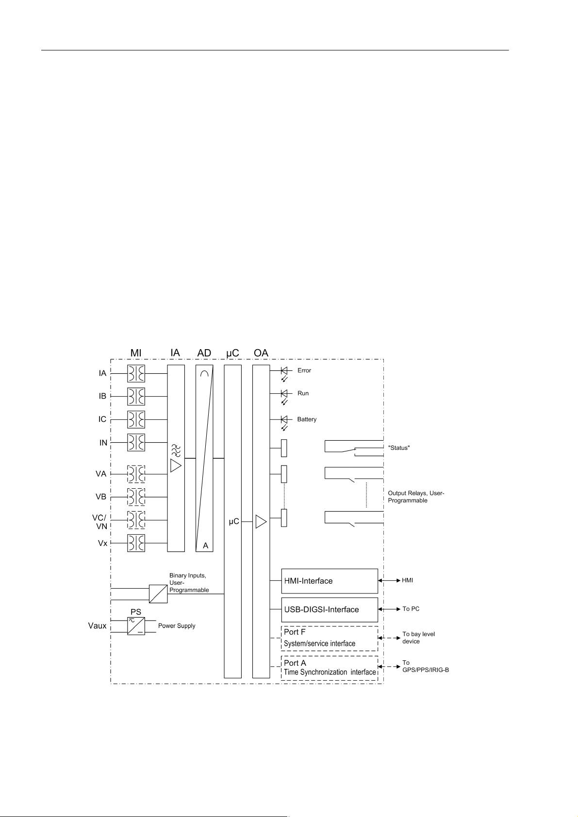
Analog Inputs
The measuring inputs (MI) convert the currents and voltages which come from the instrument transformers and
adapt them to the level appropriate for the internal processing of the device.
The merging unit device features the following connections:
• 4 conventional current transformers
• 4 conventional voltage transformers
14
Figure 1-1 Hardware structure of Merging Unit 7SC805
C53000-G1140-C380-1, Release date 05.2014
SIPROTEC, 7SC805, Manual

Microcomputer System
Apart from processing the measured values, the microcomputer system (C) also executes the control functions. They especially include:
• Filtering and preparation of the measured quantities
• Continuous monitoring of the measured quantities
• Output of control commands for switching devices
• Recording of messages, data and values for analysis
• Management of the operating system and the associated functions such as data recording, real-time clock,
communication, interfaces, etc.
• The information is distributed via output amplifiers (OA).
Binary Inputs and Outputs
The computer system obtains external information through the binary input/output boards (inputs and outputs).
The computer system obtains information from the system (e.g remote resetting) or from external equipment
(e.g. blocking commands). Outputs include, in particular, signals for the remote indication of important events
and conditions.
Front Elements
Introduction
1.1 Overall Operation
Optical displays (LEDs) on the front panel indicate whether the device is ready for operation.
HMI Interface
The HMI interface of the device is used to connect the operation panel. The operation panel can be permanently attached to the 7SC805 or it can be detached. The operation panel contains 32 LEDs for displaying operating
states or indications and a 6-line field for displaying operational indications and measured values or a graphical
field for displaying the control display. You can also operate the device using the keypads, for example activating or deactivating equipment.
Interfaces
Port F is an optical Ethernet interface to transmit SMV and exchange GOOSE messages to bay level devices
according to IEC 61850. Communication with DIGSI can be effected via the USB-DIGSI interface or via port
F (system/service interface). It should be considered that the DIGSI communication can influence the SMV
transmission.
Power Supply
A power supply unit (Vaux or PS) delivers power to the functional units using the different voltage levels. Voltage
dips may occur if the voltage supply system (substation battery) becomes short-circuited. Usually, they are
bridged by a capacitor (see also Technical Data).
A replaceable buffer battery is located on the side of the device.
SIPROTEC, 7SC805, Manual
C53000-G1140-C380-1, Release date 05.2014
15

Introduction
1.2 Application Scope
1.2 Application Scope
The Merging Unit(MU) device 7SC805 focuses on the sample values generation and transmission according
to IEC61850-9-2.
The SMV (Sample Measured Value) of 7SC80 5 can be sync hronize d via GPS or IRIG-B/PPS accurate to the microsecond.
7SC805 can also be time synchronized via GPS, IRIG-B protocol or via Ethernet interfaces with SNTP (Simple
Network Time Protocol) accurate to the microsecond.
Commissioning operational usage is similar to the other SIPROTEC4 / DIGSI4 products. Additonally, an supervision of time signals is supported.
Control Functions
The device provides a control function which can be used to activate and deactivate switching devices via the
operation panel, the Web Monitor, port F, binary inputs, and the USB interface using DIGSI.
The status of the primary equipment can be transmitted to the device via auxiliary contacts connected to binary
inputs. The present status (or position) of the primary equipment can be displayed on the device, and used for
interlocking or alarm condition monitoring. The number of operating equipments to be switched is limited by the
binary inputs and outputs available in the device or the binary inputs and outputs allocated for the switch position indications. Depending on the primary equipment being controlled, one binary input (single point indication)
or two binary inputs (double point indication) may be used for this process.
The capability of switching primary equipment can be restricted by a setting associated with switching authority
(Remote or Local), and by the operating mode (interlocked/non-interlocked, with or without password request).
Processing of interlocking conditions for switching (e.g. switchgear interlocking) can be established with the aid
of integrated, user-configurable logic functions.
The service interlocking function allows you to block switching operations which can be triggered for the con-
figured switching devices via the device.
Indications and Measured Values
The operational indications provide information about conditions in the power system and the device. Measurement quantities and values that are calculated can be displayed locally and communicated via the serial interfaces.
Device indications can be processed externally via output contacts (routable), linked with user-definable logic
functions, and/or issued via various interfaces. Furthermore, indications can be output to a number of LEDs
(routable) and displayed on the optional operation panel or using the Web Monitor.
Communication
The following interfaces are available for communication with external operating, control and memory systems.
Local communication with a PC is possible via the USB-DIGSI interface on the front. The DIGSI 4 operating
software enables you to perform all operational and evaluation tasks, for example entering and modifying configuration and setting parameters, configuring user-specific logic functions, reading out operational indications,
fault indications and measured values, reading out and displaying fault records, retrieving device conditions
and measured values, issuing control commands.
16
MU supports two optical Ethernet Interfaces for process bus communication.
PortF serves for process bus communication between merging unit and protection devices, measurement de-
vices, fault recorders, sample value receivers etc.. It can be operated via optical fiber. Standardized protocol
IEC 61850 is available for data transmission.
C53000-G1140-C380-1, Release date 05.2014
SIPROTEC, 7SC805, Manual

1.3 Characteristics
General Properties
• Powerful 32-bit microprocessor system
• Complete digital processing and control of measured value, from the sampling and digitalization of the measured quantities to close and trip decisions for the switchgear component
• Complete galvanic and interference-free isolation of the internal processing circuits of the measurement,
control and supply circuits of the system using instrument transformers, binary input and output modules,
and DC and AC voltage converters
• Easy device operation using the Web Monitor or a connected PC running DIGSI
• Continuous calculation and displaying of measured values and count values
• Continuous monitoring of the measured quantities and of the device hardware and software
• Communication with protection device and data storage equipment
• Battery-buffered clock which can be synchronized via a synchronization signal via IRIG-B and
(Simple Network Time Protocol) via Ethernet interface, or via GPS
SNTP
• Operating hours counter: Counting the operating hours of the protected object under load
• Commissioning aids such as connection and direction check, status indication of all binary inputs and outputs, easy testing of port F, and influencing of information at port F during test operation
Introduction
1.3 Characteristics
• Replacement of conventional wiring between primary and secondary devices through optical cables
• Support point to point. Using of redundant network technology (PRP, HSR)
• Use of proven SIPROTEC / DIGSI4 technology
• Easy installation and configuration supported by DIGSI and Syscon(System Configurator) via USB interface
Special Properties of Merging Unit
• Acquisition of 4 currents (1 A, 5 A) and 4 voltages (100 V, 110 V) of conventional current and voltage instrument transformers of power system data
• Accurate synchronization of the acquisition by PPS, IRIG-B or GPS signals
• Publishing sample values fully compatible with IEC 61850-9-2
• Accurate data transmission via fiber optics, no EMC disturbance on the communication
• Transmission and recept of GOOSE messages according to IEC61850 standard
• Optional support of redundancy technology HSR and PRP according IEC 62439-3 also for SMV
• Commissioning support by operational measurements and SMV records
- Proven at a temperature range of -40 to +85 °C
- Optional HMI with display, LEDs and keypad
• Configuration together with SIPROTEC 5 with IEC61850-9-2 interfaces
Device Operation
• Device operation via the Web Monitor
• Operation via operation panel. The operation panel can also be mounted detached from the device.
■
SIPROTEC, 7SC805, Manual
C53000-G1140-C380-1, Release date 05.2014
17

Introduction
1.3 Characteristics
18
C53000-G1140-C380-1, Release date 05.2014
SIPROTEC, 7SC805, Manual

Functions 2
This chapter describes the function available on the SIPROTEC Device Merging Unit 7SC805. It shows the
setting possibilities for the function. Information with regard to the determination of setting values as well as
formulas, if required, are also provided..
2.1 General 20
2.2 Merging Unit 32
2.3 Additional Functions 40
2.4 Command Processing 47
2.5 Device Operation 60
SIPROTEC, 7SC805, Manual
C53000-G1140-C380-1, Release date 05.2014
19

Functions
2.1 General
2.1 General
You can edit the function parameters via the DIGSI user interface. Some parameters can also be changed by
using the Web Monitor. The procedure is set out in the SIPROTEC System Description.
2.1.1 Functions Overview
The MU device 7SC805 features sampling functions and auxiliary functions. The hardware and firmware are
tailored to these functions. Additionally, the control functions can be matched to the system requirements. Furthermore, individual functions can be enabled or disabled during configuration, or the interaction of functions
can be modified.
2.1.1.1 Description
Setting the Scope of Functions
The available general functions can be configured as Enabled or Disabled. For some functions, there is a choice
between several alternatives possible, as described below.
Functions configured as Disabled are not processed in the 7SC805, there are no indications and the associated
setting parameters (functions, limiting values) are not available.
Note
Available functions and default settings depend on the ordered variant of the relay (see A.1 for details).
2.1.1.2 Setting Notes
Setting the Functional Scope
The MU device 7SC805 is configured by using the DIGSI software. To do so, depending on the device version
(order variant), you can connect your personal computer to :
- The USB interface on the top side of the device
- Port F on the side of the device
Operation using DIGSI is explained in the SIPROTEC 4 System Description/1/.
The Device Configuration dialog box allows you to adjust your device to the specific system conditions.
Password no. 7 is required (for parameter set) for changing configuration parameters in the device. Without the
password, the settings can only be read but not edited and transmitted to the device.
20
C53000-G1140-C380-1, Release date 05.2014
SIPROTEC, 7SC805, Manual

Special Features
Most settings are self-explanatory. The special cases are described in the following
At address 369 VT Con T ype, you can specify the connection type of the voltage inputs. If you are using normal
voltage transformers, select CONVENTIONAL.
With 459 Syscon MU Configuration, you can define whether the communication parameter configured with
System configurator or not.
With 461 PhaseIndepRatio, you can specify if the independent CT/VT ratio is supported for each channel.
Under address 700 GOOSE-Stop, you can select whether the GOOSE function of the IEC 61850 protocol is
active or not. If GOOSE-Stop is set to YES, you can release the GOOSE function again via a binary input during
the operation.
Under address 357 SMV-Stop, you can hide the information >SMV-Stop, which controlls the SMV telegram
sending function.
2.1.1.3 Settings
Functions
2.1 General
Addr. Parameter Setting Options Default Setting Comments
104 OSC. FAULT REC. Disabled
357 SMV-Stop Yes
369 VT Con Type Conventional
459 SysConMUConf Enabled
461 PhaseIndepRatio Enabled
640 Start image DD image 1
700 GOOSE-Stop Yes
2.1.1.4 Information List
Enabled
No
Cap. Volt.Meas.
Disabled
Disabled
image 2
image 3
image 4
image 5
image 6
No
Disabled Oscillographic Fault
Records
No SMV-Stop
Conventional Voltage Connection Type
Enabled MU Configuration via
IEC61850 System Configurator
Disabled Phase Independent Ratio
image 1 Start image Default
Display
No GOOSE-Stop
No. Information Type of In-
- >Light on SP >Back Light on
- Reset LED IntSP Reset LED
- DataStop IntSP Stop data transmission
- Test mode IntSP Test mode
- Feeder gnd IntSP Feeder GROUNDED
SIPROTEC, 7SC805, Manual
C53000-G1140-C380-1, Release date 05.2014
Comments
formation
21

Functions
2.1 General
No. Information Type of In-
Comments
formation
- Brk OPENED IntSP Breaker OPENED
- HWTestMod IntSP Hardware Test Mode
- SynchClock IntSP_Ev Clock Synchronization
3 >Time Synch SP_Ev >Synchronize Internal Real Time Clock
5 >Reset LED SP >Reset LED
15 >Test mode SP >Test mode
16 >DataStop SP >Stop data transmission
51 Device OK OUT Device is Operational and Protecting
55 Reset Device OUT Reset Device
56 Initial Start OUT Initial Start of Device
67 Resume OUT Resume
68 Clock SyncError OUT Clock Synchronization Error
69 DayLightSavTime OUT Daylight Saving Time
70 Settings Calc. OUT Setting calculation is running
71 Settings Check OUT Settings Check
72 Level-2 change OUT Level-2 change
110 Event Lost OUT_Ev Event Lost
113 Flag Lost OUT Flag Lost
125 Chatter ON OUT Chatter ON
140 Error Sum Alarm OUT Error with a summary alarm
160 Alarm Sum Event OUT Alarm Summary Event
177 Fail Battery OUT Failure: Battery empty
178 I/O-Board error OUT I/O-Board Error
191 Error Offset OUT Error: Offset
193 Alarm NO calibr OUT Alarm: NO calibration data available
320 Warn Mem. Data OUT Warn: Limit of Memory Data exceeded
321 Warn Mem. Para. OUT Warn: Limit of Memory Parameter exceeded
322 Warn Mem. Oper. OUT Warn: Limit of Memory Operation exceeded
323 Warn Mem. New OUT Warn: Limit of Memory New exceeded
335 >GOOSE-Stop OUT >GOOSE-Stop
373.3001 HotLineTag int. IntSP Hot Line Tag internal trigger
373.3002 HotLineTag ext. IntSP Hot Line Tag external trigger
2172 GPS ModuleError OUT GPS Module Error
2186 Error IO board OUT Error occurred on IO board
2240 Multi. routing OUT Several indications routed
2534 HotLineTag act. OUT Hot Line Tag is active, no operation
2535 >HotLineTag ext SP >Hot Line Tag external trigger
17566 Dist.CFC Src VI Disturbance CFC Source
31017 >SMV-Stop SP >Sample Value-Stop
22
C53000-G1140-C380-1, Release date 05.2014
SIPROTEC, 7SC805, Manual

2.1.2 Power System Data 1
2.1.2.1 Description
The device requires certain data regarding the network and substation so that it can adapt its functions to this
data depending on the application. This may be, for instance, nominal data of the substation and measuring
transformers, polarity and connection of the measured quantities, breaker properties (where applicable), etc.
There are also certain parameters that are common to all functions, i.e. not associated with a specific control
or monitoring function. The following section discusses this data.
2.1.2.2 Setting Notes
Functions
2.1 General
The following parameters are only for CTs and VTs. For the other special setting notes of Merging Unit, please
refer to chapter
figuration.These two configurations share some common parameters and also have their own parameters.
General
In DIGSI, double-click Settings to open the corresponding dialog box. In doing so, a dialog box with tabs opens
under P.System Data 1, in which individual parameters can be configured. The following descriptions are there-
fore structured according to these tabs.
Rated Frequency (Power System)
The rated system frequency is set at address 0214 Rated Frequency. The factory setting of the model number
must only be changed if the device is to be used for a different purpose than intended when ordering. Parameter
214 is preset to 50 Hz.
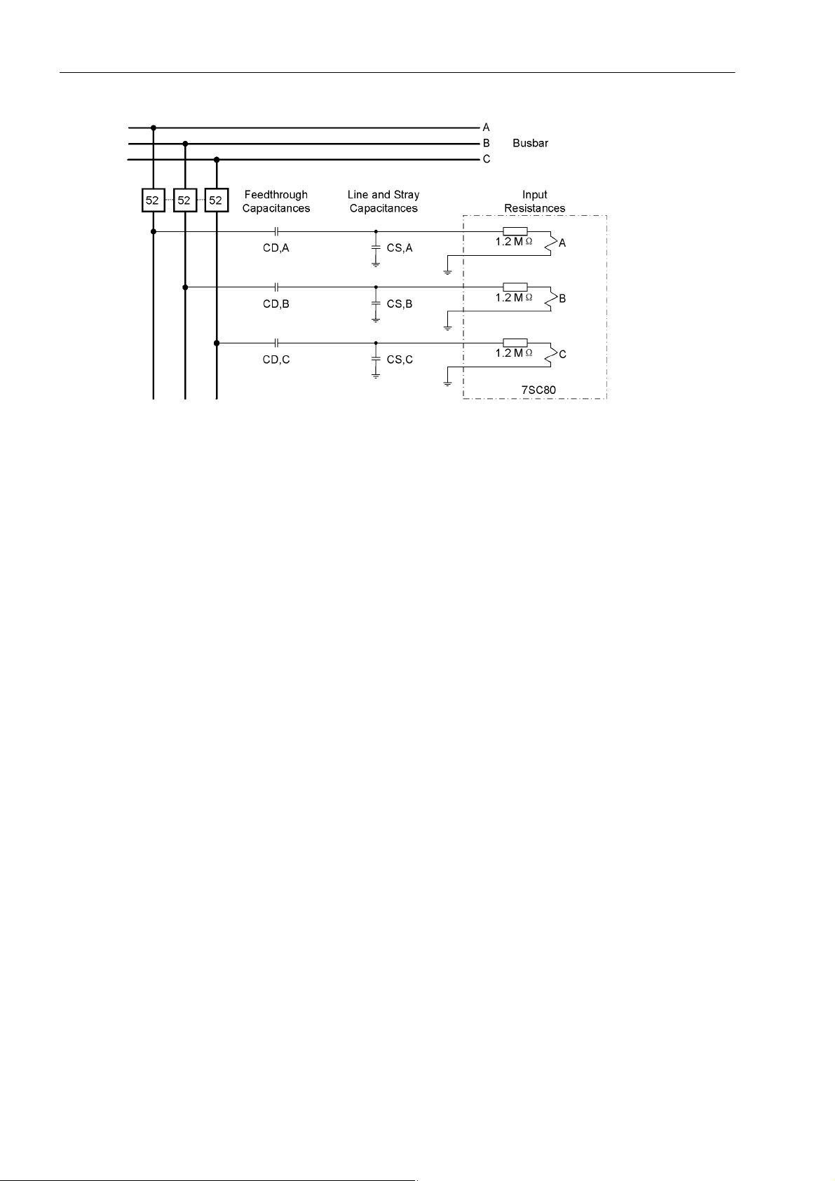
Capacitive Voltage Measurement
If you select the setting Cap. Volt.Meas. at address 369 VT Con Type, the voltage is measured via so-called
bushing capacitances. The inductive primary voltage transformers normally used are not used in this case. Capacitive voltage measurement always measures the phase-to-ground voltages from the device. The following
figure shows this type of connection.
2.2.2
. There are two possibilities for configuring CTs and VTs: 1-phase or 3-phase system con-
SIPROTEC, 7SC805, Manual
C53000-G1140-C380-1, Release date 05.2014
23
Functions
2.1 General
Figure 2-1 Connection Principle for a Capacitive Voltage Measurement
In addition to the bushing capacitances, the line and stray capacitances also affect the measured voltage fed
to the protection device. These capacitances are primarily determined by the type and length of the connection
line.
The voltage inputs of the device have a resistive component of 1.2 M.
Two capacitance values must be configured for each of the three voltage inputs when using capacitive voltage
measurement.
• The first value to be configured is the bushing capacitance (C
D,Lx
• The second value to be configured is the sum of the line and stray capacitance (C
The capacitances are configured as follows:
Phase A 241 Volt.trans.A:C1
242 Volt.trans.A:C2
Phase B 243 Volt.trans.B:C1
244 Volt.trans.B:C2
Phase C 245 Volt.trans.C:C1
246 Volt.trans.C:C2
= C
= C
= C
= C
= C
= C
D,A
S,A
D,B
S,B
D,C
S,C
Nominal Values of Current Transformers (CTs) (Only For 3-phase System)
At addresses 204 CT PRIMARY and 205 CT SECONDARY information is entered regarding the primary and
secondary ampere ratings of the current transformers. It is important to ensure that the rated secondary current
of the current transformer matches the rated current of the device, otherwise the device will calculate incorrect
primary data. At addresses 217 Ignd-CT PRIM and 218 Ignd-CT SEC, information is entered regarding the
primary and secondary ampere rating of the current transformers. In case of a normal connection (starpoint
current connected to I
transformer), 217 Ignd-CT PRIM and 204 CT PRIMARY must be set to the same value.
N
).
).
S,Lx
Nominal Values of Current Transformers (CTs) (Only For 1-phase System)
Currently 4 channels current are supported. Each channel has its own configuration regarding to the primary
and secondary ampere ratings of the current transformers. Address 562, 564, 566,568 are for Channel Rated
Primary Current Values, and Address 563,565,567, 569 are for Channel Rated Second Current Values. These
addresses are important to ensure that the rated secondary current of the current transformer matches the
rated current of the device, otherwise the device will calculate incorrectly.
24
C53000-G1140-C380-1, Release date 05.2014
SIPROTEC, 7SC805, Manual

Nominal Values of Voltage Transformers (VTs) (Only For 3-phase System)
At addresses 202 Vnom PRIMAR Y and 203 Vnom SECONDARY, information is entered regarding the primary
nominal voltage and secondary nominal voltage (phase-to-phase) of the connected voltage transformers.
At addresses 333 Vnom prim Vx and 325 Vnom sec Vx, you can enter the primary and secondary rated voltage
for the 4th voltage input Vx.
Current Clipping Limit Ratio
Address 480 ClipC informs the ratio of the clipping limit of the instantaneous current to the rated primary voltage
multiplied with a square root of two. For example “clip=20” applied with rated primary current of IP
means clipping will occur at ±14140A
Primary currents with magnitude above the clipping limit may satu-
PEAK.
rate analogue circuits and/or digital filters within the instrument transformer resulting in highly inaccurate
sampled values
V o ltage Clipping Limit Ratio
Address 481 ClipV informs the ratio of the clipping limit of the instantaneous voltage to the rated primary voltage
multiplied with a square root of two. For example “clip=2” applied with rated primary voltage of UP
means clipping may occur at ±14.14 kV
. Primary voltages with magnitude above the clipping limit may sat-
PEAK
urate analogue circuits and/or digital filters within the instrument transformer resulting in highly inaccurate
sampled values
Functions
2.1 General
=500A
r
RMS
=5 kV
r
RMS
Nominal Values of Voltage Transformers (VTs) (Only For 1-phase System)
Currently 4 channels voltage are supported. Every channel has its own configuration. Address 570, 572, 574,576
are for Channel Rated Primary Volatge Values, and Address 571,573,575, 577 are for Channel Rated Second
Voltage Values. At these addresses, information is entered regarding to the primary nominal voltage and secondary nominal voltage (phase independent) of the connected voltage transformers
2.1.2.3 Settings
The table indicates region-specific default settings.
For clear reference, parameters for 1-phase and 3-phase are listed respectively.
Table 3: Settings For 3-phase Ratio
Addr. Parameter C Setting Options Default Setting Comments
202 Vnom PRIMARY 0.10 .. 800.00 kV 20.00 kV Rated Primary Voltage
203 Vnom
SECONDARY
204 CT PRIMARY 10 .. 50000 A 400 A CT Rated Primary Current
205 CT SECONDARY 1 A
214 Rated Frequency 50 Hz
34 .. 400 V 100 V Rated Secondary Voltage (L-L)
1A CT Rated Secondary Current
5 A
50Hz Rated Frequency
60 Hz
217 Ignd-CT PRIM 1 .. 50000 A 400 A Ignd-CT rated primary current
218 Ignd-CT SEC 1 A
325 Vnom sec Vx 34 .. 230 kV 100 kV Rated Secondary Voltage Vx
SIPROTEC, 7SC805, Manual
C53000-G1140-C380-1, Release date 05.2014
5 A
1 A Ignd-CT rated secondary
current
25

Functions
2.1 General
Table 3: Settings For 3-phase Ratio
Addr. Parameter C Setting Options Default Setting Comments
333 Vnom prim Vx 0.10 .. 800.00 kV 20.00 kV Rated Primary Voltage Vx
352 U4 inverting YES
No U4 inverting
NO
480 ClipC 1 .. 57 20 Clip Current Limit
481 ClipV 1 .. 11 2 Clip Voltage Limit
482 CurAccuClass 0.2/1 P
0.2/1 P Current Accuracy Class
0.2 S/1 P
0.5/1 P
0.5 S/1 P
1/1 P
0.2/5 P
0.2 S/5 P
0.5/5 P
0.5 S/5 P
1/5 P
483 VolAccuClass 0.2/1 P
0.2/1 P Voltage Acurrency Class
0.2 S/1 P
0.5/1 P
0.5 S/1 P
1/1 P
0.2/5 P
0.2 S/5 P
0.5/5 P
0.5 S/5 P
1/5 P
Table 4: Settings For 1-phase Ratio
Addr. Parameter C Setting Options Default Setting Comments
214 Rated Frequency 50 Hz
60 Hz
352 U4 inverting YES
NO
480 ClipC 1 .. 57 20 Clip Current Limit
481 ClipV 1 .. 11 2 Clip Voltage Limit
482 CurAccuClass 0.2/1 P
0.2 S/1 P
0.5/1 P
0.5 S/1 P
1/1 P
0.2/5 P
0.2 S/5 P
0.5/5 P
0.5 S/5 P
1/5 P
50Hz Rated Frequency
No U4 inverting
0.2/1 P Current Accuracy Class
26
C53000-G1140-C380-1, Release date 05.2014
SIPROTEC, 7SC805, Manual

Table 4: Settings For 1-phase Ratio
Addr. Parameter C Setting Options Default Setting Comments
Functions
2.1 General
483 VolAccuClass 0.2/1 P
0.2/1 P Voltage Acurrency Class
0.2 S/1 P
0.5/1 P
0.5 S/1 P
1/1 P
0.2/5 P
0.2 S/5 P
0.5/5 P
0.5 S/5 P
1/5 P
562 Ch1RatedPrimCur 10.. 50000 A 400 A Channel1 Rated Primary
Current
563 Ch1RatedSecCur 1 A
5 A
1 A Channel1 Rated Second
Current
564 Ch2RatedPrimCur 10.. 50000 A 400 A Channel2 Rated Primary
Current
565 Ch2RatedSecCur 1 A
5 A
1 A Channel2 Rated Second
Current
566 Ch3RatedPrimCur 10.. 50000 A 400 A Channel3 Rated Primary
Current
567 Ch3RatedSecCur 1 A
5 A
1 A Channel3 Rated Second
Current
568 Ch4RatedPrimCur 10.. 50000 A 400 A Channel4 Rated Primary
Current
569 Ch4RatedSecCur 1 A
5 A
1 A Channel4 Rated Second
Current
570 Ch1RatedPrimVol 0.10 .. 800.00 kV 20.00 kV Channel1 Rated Primary
Voltage
571 Ch1RatedSecVol 34.. 400 V 100 V Channel1 Rated Second
Voltage
572 Ch2RatedPrimVol 0.10 .. 800.00 kV 20.00 kV Channel2 Rated Primary
Voltage
573 Ch2RatedSecVol 34.. 400 V 100 V Channel2 Rated Second
Voltage
574 Ch3RatedPrimVol 0.10 .. 800.00 kV 20.00 kV Channel3 Rated Primary
Voltage
575 Ch3RatedSecVol 34.. 400 V 100 V Channel3 Rated Second
Voltage
576 Ch4RatedPrimVol 0.10 .. 800.00 kV 20.00 kV Channel4 Rated Primary
Voltage
577 Ch4RatedSecVol 34.. 400 V 100 V Channel4 Rated Second
Voltage
For other settings belonging to Power System Data 1 and special for Merging Unit, please refer to chapter
2.2.2
.
SIPROTEC, 7SC805, Manual
C53000-G1140-C380-1, Release date 05.2014
27

Functions
2.1 General
2.1.3 Oscillographic Fault Records(Waveform Capture)
The Merging Unit 7SC805 features a fault record memory. It is used for commissioning. It can be triggered by
indications from GOOSE message, CFC and binary input. The instantaneous values for
i
, iB, iC, iN and vA, vB, vC, v
A
X
are sampled at intervals of 1.0 ms (at 50 Hz) and stored in a circular buffer (20 samples per cycle). The data is
stored for a set period of time, but not for more than 6 seconds. Up to 8 events can be recorded in this buffer.
The fault record memory is automatically updated with every new event so that there is no acknowledgment for
previously recorded faults required.
2.1.3.1 Description
The data of a event record can be read out via the device interface and evaluated with the help of the SIGRA
4 graphic analysis software. SIGRA 4 graphically represents the data recorded during the event and also calculates additional information from the measured values. Currents and voltages can be presented either as
primary or as secondary values. Signals are additionally recorded as binary tracks (marks).
If port F of the device has been configured correspondingly, a control centre can import and evaluate the event
record data via this interface. Currents and voltages are prepared for a graphic representation. Signals are additionally recorded as binary tracks (marks).
The following measured values are recorded in the fault record:
Phase Independent Ratio
Three Phase (Van, Vbn, Vcn) One Phase
V
A
V
B
V
C
V
x
Note
Chnanel1 Voltage
Chnanel2 Voltage
Chnanel3 Voltage
Chnanel4 Voltage
The signals used for the binary inputs can be allocated in DIGSI.
28
C53000-G1140-C380-1, Release date 05.2014
SIPROTEC, 7SC805, Manual

2.1.3.2 Setting Notes
Configuration
Fault recording (waveform capture) will only take place if address 104 OSC. F AULT REC. is set to Enabled.
Other settings pertaining to fault recording (waveform capture) are found in the OSC. FAULT REC. submenu
of the SETTINGS menu.
The actual storage time begins at the pre-fault time PRE. TRIG. TIME (address 404) ahead of the reference
instant, and ends at the post-fault time POST REC. TIME (address 405) after the storage criterion has reset.
The maximum storage time for each fault recording (MAX. LENGTH) is entered in address 403. Recording per
event must not exceed 6 seconds. A total of 8 records can be saved. However, the total length of time of all
fault records in the buffer must not exceed 18 seconds.
An oscillographic record can be triggered by a status change of a binary input, or from a PC via the operator
interface. Storage is then triggered dynamically. The length of the fault recording is set in address 406 BinIn
CAPT.TIME (but not longer than MAX. LENGTH, address 403). Pre-fault and post-fault times will add to this.
If the binary input time is set to , the length of the record equals the time that the binary input is activated
(static), but not longer than the MAX. LENGTH (address 403).
2.1.3.3 Settings
Functions
2.1 General
Addr. Parameter Setting Options Default Setting Comments
403 MAX. LENGTH 0.30 .. 6.00 sec 2.00 sec Max. length of a Waveform
404 PRE. TRIG. TIME 0.05 .. 0.50 sec 0.25 sec Captured Waveform Prior to
405 POST REC. TIME 0.05 .. 0.50 sec 0.10 sec Captured Waveform after Event
406 BinIn CAPT.TIME 0.10 .. 5.00 sec; 0.50 sec Capture Time via Binary Input
2.1.3.4 Information List
No. Information T ype of Information Comments
- FltRecSta IntSP Fault Recording Start
4 >Trig.Wave.Cap. SP >Trigger Waveform Capture
203 Wave. deleted OUT_Ev Waveform data deleted
30053 Fault rec. run. OUT Fault recording is running
2.1.4 Power System Data 2
Capture Record
Trigger
2.1.4.1 Description
The general data (P.System Dat a 2) include parameters common to all functions, i.e. not associated with a specific monitoring function. In contrast to the P.System D ata 1 before, they can be changed with the parameter
group.
SIPROTEC, 7SC805, Manual
C53000-G1140-C380-1, Release date 05.2014
29

Functions
2.1 General
If the primary reference voltage and the primary reference current of the protected object are specified, the
device can calculate and issue the percentage operational measured values.
2.1.4.2 Setting Notes
Definition of Nominal Rated Values
At addresses 1101 FullScaleVolt. and 1102 FullScaleCurr., the primary reference voltage (phase-to-phase) and
reference current (phase) of the protected equipment is entered (e.g. motors). If these reference sizes match
the primary nominal values of the VTs and CTs, they correspond to the settings in address 202 and 204 (Section
2.1.2.3). They are generally used to show values referenced to full scale.
2.1.4.3 Settings
The table indicates region-specific default settings.
Addr. Parameter C Setting Options Default Setting Comments
1101 FullScaleVolt. 0.10 .. 800.00 kV 20.00 kV Measurem:FullScaleVolt-
1102 FullScaleCurr. 10 .. 50000 A 400 A Measurem:FullScaleCur-
age(Equipm.rating)
rent(Equipm.rating)
2.1.4.4 Information List
No. Information Type of Information Comments
356 >Manual Close SP >Manual close signal
420 >Opened Ctrl 2 SP >Opened Control device 2
421 >Opened Ctrl 3 SP >Opened Control device 3
422 >Closed Ctrl 2 SP >Closed Control device 2
423 >Closed Ctrl 3 SP >Closed Control device 3
424 Open Ctrl 2 OUT Open control device 2
425 Close Ctrl 2 OUT Close control device 2
426 Open Ctrl 3 OUT Open control device 3
427 Close Ctrl 3 OUT Close control device 3
533 IL1 = VI Primary fault current Ia
534 IL2 = VI Primary fault current Ib
535 IL3 = VI Primary fault current Ic
561 Man.Clos.Detect OUT Manual close signal detected
4601 >Brk Aux NO SP >Breaker contact(OPEN, if breaker is open)
4602 >Brk Aux NC SP >Breaker contact(OPEN, if breaker is closed)
30
C53000-G1140-C380-1, Release date 05.2014
SIPROTEC, 7SC805, Manual
 Loading...