

Page 1

SIPROTEC
3UHIDFH
,QWURGXFWLRQ 1
)XQFWLRQV 2
0RXQWLQJDQG&RPPLVVLRQLQJ 3
Distanc e Prot ection
7SA522
V4.3
Manual
7HFKQLFDO'DWD 4
$SSHQGL[ A
/LWHUDWXUH
*ORVVDU\
,QGH[
C53000-G1176-C155-3
Page 2

Disclaimer of liability
We have checked the text of this manual against the hardware
and software described. However, deviations from the description cannot be completely ruled out, so that no liability can be accepted for any errors or omissions contained in the information
given.
The information in this manual is checked periodically, and necessary corrections will be included in future editions. We appreciate any suggested improvements.
We reserve the right to make technical improvements without
notice.
Copyright
Copyright © Siemens AG 2003. All rights reserved.
Dissemination or reproduction of this document, or evaluation
and communication of its contents, is not authorized except
where expressly permitted. Violations are liable for damages. All
rights reserved, particularly for the purposes of patent application
or trademark registration.
Registered Trademarks
SIPROTEC, SINAUT, SICAM and DIGSI are registered trademarks of SIEMENS AG. Other designations in this manual may
be trademarks that if used by third parties for their own purposes
may violate the rights of the owner.
Release 4.30.01
7SA522 Manual
C53000-G1176-C155-3
Page 3
Preface
Purpose of this Manual
This manual describes the functions, operation, installation, and placing into service
of device 7SA522. In particular, one will find:
• Descriptions of device functions and settings;
• Instructions for mounting and commi s sioni ng;
• Compilation of the technical specifications;
• As well as a co mpilation of the most significant data for experienced users in the
Appendix.
General information about design, configuration, and operation of SIPROTEC
devices are laid down in the SIPROTEC
®
4 System Description
®
4
(Order no.: E50417-H1176-C151-A1).
T a rget Audience Protection engineers, commissioning engineers, personnel concerned with adjust-
ment, checking, and service of selective protective equipment, automatic and control
facilities, and personnel of electrical facilities and power plants.
Applicability of this Manual
This manual is valid for Distance Protection Device SIPROTEC
Firmware Version V4.3
®
4 7SA522;
Indication of Conformity
This product compli es with the d irecti ve of th e Cou ncil of the Euro pean Com muni ties on the app roximati on of the l aws of th e Me mber States relat ing to elec tromag netic compatibility (EMC Council Directive 89/336/EEC) and concerning electrical
equipment for use within specified voltage limits (Low-voltage directive 73/23
EEC).
This conformity is proved by tests conducted by Siemens AG in accordance with
Article 10 of the Counc il Directive in agreement with the generic standards EN
50081 and EN 61 000-6-2 for EMC directive, and with the standard EN 60 255-6
for the low- voltage directive.
The product conforms with the international standard of the series IEC 60 255 and
the German standard VDE 0435.
Further Standa rds IEEE Std C37.90-*
This product is UL-certified according to the Technical Data:
C53000-G1176-C155-3
37SA522 Manual
Page 4

Preface
Additional Support Should further information on the System SIPROTEC® 4 be desired or should partic-
ular problems arise which are not covered sufficiently for the purchaser's purpose, the
matter should be referred to the local Siemens representative.
Training Courses Individual course offerings may be found in our Training Catalogue, or questions may
be directed to our training centre in Nuremberg.
Instructions and
Warnings
The warnings and notes contained in this manual serve for your own safety and for
an appropriate lifetime of the device. Please observe them!
The following indicators and standard definitions are used:
DANGER!
indicates that death, severe personal injury or substantial property damage will
result if proper precautions are not taken.
Warning
indicates that death, severe personal injury or substantial property damage can
result if proper precautions are not taken.
Caution
indicates that minor personal injury or property damage can result if proper precautions are not taken. This particularly applies to damage on or in the device itself and
consequential damage thereof.
1RWH
indicates information about the device or respective part of the instruction manual
which is essential to highlight.
WARNING!
Hazardous voltages are present in this electrical equipment during operation.
Failure to observe these precautions can result in death, personal injury, or serious
material damage.
Only qualified personnel shall work on and in the vicinity of this equipment. The per-
sonnel must be thoroughly familiar with all warnings and maintenance procedures of
this manual as well as the safety regulations.
Successful and safe operation of the device is dependent on proper transportation,
storage, mounting and assembly and the observance of the warnings and instructions
of the unit manual.
Of particular importance are the general installation and safety regulations for work in
a high-voltage environment (for example, VDE, IEC, EN, DIN, or other national and
international regulations). These regulations must be observed.
4
7SA522 Manual
C53000-G1176-C155-3
Page 5

Definition QUALIFIED PERSONNEL
Prerequisites to proper and safe operation of this product are proper transport,
proper storage, setup, installation, operation, and maintenance of the product, as
well as careful operation and servicing of the device within the scope of the warnings and instructions of this manual.
• Is trained and authorized to energize, de-energize, clear, ground and tag circuits
and equipment in accordanc e with establ is hed safety practi ce s.
• Training and instruction (or other qualification) for switching, grounding, and designating devices and systems.
• Is trained in rendering first aid.
Preface
Typographic and
Graphical Conventions
To designate terms which refer in the text to information of the device or for the
device, the following fonts are used:
3DUDPHWHUQDPHV
Designators of configuration or function parameters which may appear word-forword in the display of the device or on the screen of a personal computer (with operation software DIGSI
®
), are marked in bold letters of a monospace type style. This
also applies to header bars for selection menus.
$
Parameter addresses have the same character style as parameter names. Parameter addresses contain the suffix $ in the overview tables if the parameter can only
be set in DIGSI
®
via the option Display additional settings.
3DUDPHWHU&RQGLWLRQV
possible settings of text parameters, which may appear word-for-word in the display
of the device or on the screen of a personal computer (with operation software DIG-
®
SI
), are additionally written in italics. This also applies to header bars for selection
menus.
´$QQXQFLDWLRQVµ
Designators for information, which may be output by the relay or required from other
devices or from the switch gear, are marked in a monospace type style in quotation
marks.
Deviations may be permitted in drawings and tables when the type of designator can
be obviously derived from the illustration.
7SA522 Manual
C53000-G1176-C155-3
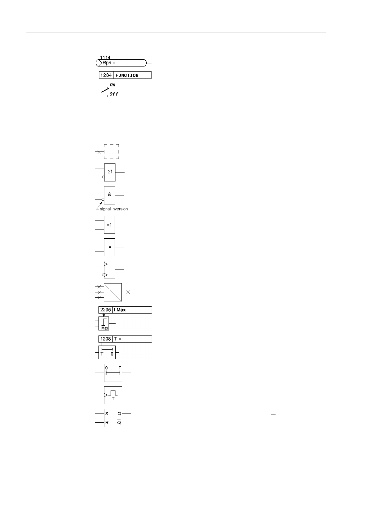
The following symbols are used in drawings:
device-internal logical input signal
device-internal (logical) output signal
internal input signal of an analogue quantity
external binary input signal with number (binary input, input
indication)
external binary output signal with number (device indication)
5
Page 6
Preface
external binary output signal with number (device indication)
used as input signal
Example of a p arameter sw itch designat ed FUNCTION with
the address 1234 and the possible settings ON and OFF
Besides these, graphical symbols are used according to IEC 60 617-12 and IEC 60
617-13 or symbols derived from these standards. Some of the most frequently used
are listed below:
Input signal of an analogue quantity
OR gate
AND gate
Exclusive–OR gate (antivalence): output is active, if only
one of the inputs is active
Equivalence: output is active, if both inputs are active or inactive at the same time
Dynamic inputs (edge–triggered) above with positive, below
with negative edge
Formation of one analogue output signal from a number of
analogue input signals
Limit stage with setting address and parameter designator
(name)
Timer (pickup delay T, example adjustable) with setting
address and parameter designator (name)
Timer (dropout delay T, example non-adjustable)
Dynamic triggered pulse timer T (monoflop)
Static memory (RS-flipflop) with setting input (S), resetting
input (R), output (Q) and inverted output (Q
)
■
6
7SA522 Manual
C53000-G1176-C155-3
Page 7

Contents
1 Introduction. . . . . . . . . . . . . . . . . . . . . . . . . . . . . . . . . . . . . . . . . . . . . . . . . . . . . . . . . . . . . . . . . . . . 17
1.1 Overall Operation . . . . . . . . . . . . . . . . . . . . . . . . . . . . . . . . . . . . . . . . . . . . . . . . . . . . . . . . 18
1.2 Application Scope . . . . . . . . . . . . . . . . . . . . . . . . . . . . . . . . . . . . . . . . . . . . . . . . . . . . . . . . 22
1.3 Characteristics. . . . . . . . . . . . . . . . . . . . . . . . . . . . . . . . . . . . . . . . . . . . . . . . . . . . . . . . . . . 25
2 Functions. . . . . . . . . . . . . . . . . . . . . . . . . . . . . . . . . . . . . . . . . . . . . . . . . . . . . . . . . . . . . . . . . . . . . . 31
2.1 General . . . . . . . . . . . . . . . . . . . . . . . . . . . . . . . . . . . . . . . . . . . . . . . . . . . . . . . . . . . . . . . . 32
2.1.1 Functional Scope. . . . . . . . . . . . . . . . . . . . . . . . . . . . . . . . . . . . . . . . . . . . . . . . . . . . . . . . . 32
2.1.1.1 Configuration of the Functional Scope . . . . . . . . . . . . . . . . . . . . . . . . . . . . . . . . . . . . . . . . 32
2.1.1.2 Setting Notes. . . . . . . . . . . . . . . . . . . . . . . . . . . . . . . . . . . . . . . . . . . . . . . . . . . . . . . . . . . . 32
2.1.1.3 Settings . . . . . . . . . . . . . . . . . . . . . . . . . . . . . . . . . . . . . . . . . . . . . . . . . . . . . . . . . . . . . . . . 35
2.1.2 Device . . . . . . . . . . . . . . . . . . . . . . . . . . . . . . . . . . . . . . . . . . . . . . . . . . . . . . . . . . . . . . . . . 37
2.1.2.1 Trip Dependent Messages . . . . . . . . . . . . . . . . . . . . . . . . . . . . . . . . . . . . . . . . . . . . . . . . . 37
2.1.2.2 Spontaneous Annunciations on the Display . . . . . . . . . . . . . . . . . . . . . . . . . . . . . . . . . . . . 37
2.1.2.3 Setting Notes. . . . . . . . . . . . . . . . . . . . . . . . . . . . . . . . . . . . . . . . . . . . . . . . . . . . . . . . . . . . 38
2.1.2.4 Settings . . . . . . . . . . . . . . . . . . . . . . . . . . . . . . . . . . . . . . . . . . . . . . . . . . . . . . . . . . . . . . . . 38
2.1.2.5 Information List . . . . . . . . . . . . . . . . . . . . . . . . . . . . . . . . . . . . . . . . . . . . . . . . . . . . . . . . . . 38
2.1.3 Power System Data 1 . . . . . . . . . . . . . . . . . . . . . . . . . . . . . . . . . . . . . . . . . . . . . . . . . . . . . 40
2.1.3.1 Setting Notes. . . . . . . . . . . . . . . . . . . . . . . . . . . . . . . . . . . . . . . . . . . . . . . . . . . . . . . . . . . . 40
2.1.3.2 Settings . . . . . . . . . . . . . . . . . . . . . . . . . . . . . . . . . . . . . . . . . . . . . . . . . . . . . . . . . . . . . . . . 44
2.1.4 Setting Group Changeover . . . . . . . . . . . . . . . . . . . . . . . . . . . . . . . . . . . . . . . . . . . . . . . . . 46
2.1.4.1 Purpose of the Setting Groups . . . . . . . . . . . . . . . . . . . . . . . . . . . . . . . . . . . . . . . . . . . . . . 46
2.1.4.2 Setting Notes. . . . . . . . . . . . . . . . . . . . . . . . . . . . . . . . . . . . . . . . . . . . . . . . . . . . . . . . . . . . 46
2.1.4.3 Settings . . . . . . . . . . . . . . . . . . . . . . . . . . . . . . . . . . . . . . . . . . . . . . . . . . . . . . . . . . . . . . . . 46
2.1.4.4 Information List . . . . . . . . . . . . . . . . . . . . . . . . . . . . . . . . . . . . . . . . . . . . . . . . . . . . . . . . . . 47
2.1.5 Power System Data 2 . . . . . . . . . . . . . . . . . . . . . . . . . . . . . . . . . . . . . . . . . . . . . . . . . . . . . 47
2.1.5.1 Setting Notes. . . . . . . . . . . . . . . . . . . . . . . . . . . . . . . . . . . . . . . . . . . . . . . . . . . . . . . . . . . . 47
2.1.5.2 Settings . . . . . . . . . . . . . . . . . . . . . . . . . . . . . . . . . . . . . . . . . . . . . . . . . . . . . . . . . . . . . . . . 57
2.1.5.3 Information List . . . . . . . . . . . . . . . . . . . . . . . . . . . . . . . . . . . . . . . . . . . . . . . . . . . . . . . . . . 58
2.1.6 Oscillographic Fault Records. . . . . . . . . . . . . . . . . . . . . . . . . . . . . . . . . . . . . . . . . . . . . . . . 60
2.1.6.1 Description . . . . . . . . . . . . . . . . . . . . . . . . . . . . . . . . . . . . . . . . . . . . . . . . . . . . . . . . . . . . . 60
2.1.6.2 Setting Notes. . . . . . . . . . . . . . . . . . . . . . . . . . . . . . . . . . . . . . . . . . . . . . . . . . . . . . . . . . . . 60
2.1.6.3 Settings . . . . . . . . . . . . . . . . . . . . . . . . . . . . . . . . . . . . . . . . . . . . . . . . . . . . . . . . . . . . . . . . 61
2.1.6.4 Information List . . . . . . . . . . . . . . . . . . . . . . . . . . . . . . . . . . . . . . . . . . . . . . . . . . . . . . . . . . 61
C53000-G1176-C155-3
77SA522 Manual
Page 8

Contents
2.2 Distance protection . . . . . . . . . . . . . . . . . . . . . . . . . . . . . . . . . . . . . . . . . . . . . . . . . . . . . . . 62
2.2.1 Distance protection, general settings. . . . . . . . . . . . . . . . . . . . . . . . . . . . . . . . . . . . . . . . . . 62
2.2.1.1 Earth Fault Detection. . . . . . . . . . . . . . . . . . . . . . . . . . . . . . . . . . . . . . . . . . . . . . . . . . . . . . 62
2.2.1.2 Calculation of the Impedances . . . . . . . . . . . . . . . . . . . . . . . . . . . . . . . . . . . . . . . . . . . . . . 65
2.2.1.3 Setting Notes. . . . . . . . . . . . . . . . . . . . . . . . . . . . . . . . . . . . . . . . . . . . . . . . . . . . . . . . . . . . 72
2.2.1.4 Settings . . . . . . . . . . . . . . . . . . . . . . . . . . . . . . . . . . . . . . . . . . . . . . . . . . . . . . . . . . . . . . . . 76
2.2.1.5 Information List . . . . . . . . . . . . . . . . . . . . . . . . . . . . . . . . . . . . . . . . . . . . . . . . . . . . . . . . . . 77
2.2.2 Distance protection with quadrilateral characteristic (optional) . . . . . . . . . . . . . . . . . . . . . . 80
2.2.2.1 Method of Operation . . . . . . . . . . . . . . . . . . . . . . . . . . . . . . . . . . . . . . . . . . . . . . . . . . . . . . 80
2.2.2.2 Setting Notes. . . . . . . . . . . . . . . . . . . . . . . . . . . . . . . . . . . . . . . . . . . . . . . . . . . . . . . . . . . . 86
2.2.2.3 Settings . . . . . . . . . . . . . . . . . . . . . . . . . . . . . . . . . . . . . . . . . . . . . . . . . . . . . . . . . . . . . . . . 90
2.2.3 Distance protection with MHO characteristic (optional). . . . . . . . . . . . . . . . . . . . . . . . . . . . 92
2.2.3.1 Functional Description . . . . . . . . . . . . . . . . . . . . . . . . . . . . . . . . . . . . . . . . . . . . . . . . . . . . . 92
2.2.3.2 Setting Notes. . . . . . . . . . . . . . . . . . . . . . . . . . . . . . . . . . . . . . . . . . . . . . . . . . . . . . . . . . . . 97
2.2.3.3 Settings . . . . . . . . . . . . . . . . . . . . . . . . . . . . . . . . . . . . . . . . . . . . . . . . . . . . . . . . . . . . . . . 101
2.2.4 Tripping Logic of the Distance Protection . . . . . . . . . . . . . . . . . . . . . . . . . . . . . . . . . . . . . 102
2.2.4.1 Functional Description . . . . . . . . . . . . . . . . . . . . . . . . . . . . . . . . . . . . . . . . . . . . . . . . . . . . 102
2.2.4.2 Setting Notes. . . . . . . . . . . . . . . . . . . . . . . . . . . . . . . . . . . . . . . . . . . . . . . . . . . . . . . . . . . 107
2.3 Power swing detection (optional). . . . . . . . . . . . . . . . . . . . . . . . . . . . . . . . . . . . . . . . . . . . 108
2.3.1 Function Description . . . . . . . . . . . . . . . . . . . . . . . . . . . . . . . . . . . . . . . . . . . . . . . . . . . . . 108
2.3.2 Setting Notes. . . . . . . . . . . . . . . . . . . . . . . . . . . . . . . . . . . . . . . . . . . . . . . . . . . . . . . . . . . 113
2.3.3 Settings . . . . . . . . . . . . . . . . . . . . . . . . . . . . . . . . . . . . . . . . . . . . . . . . . . . . . . . . . . . . . . . 114
2.3.4 Information List . . . . . . . . . . . . . . . . . . . . . . . . . . . . . . . . . . . . . . . . . . . . . . . . . . . . . . . . . 114
2.4 Protection data interfaces and communication topology (optional). . . . . . . . . . . . . . . . . . 115
2.4.1 Function Description . . . . . . . . . . . . . . . . . . . . . . . . . . . . . . . . . . . . . . . . . . . . . . . . . . . . . 115
2.4.2 Setting Notes. . . . . . . . . . . . . . . . . . . . . . . . . . . . . . . . . . . . . . . . . . . . . . . . . . . . . . . . . . . 118
2.4.3 Settings . . . . . . . . . . . . . . . . . . . . . . . . . . . . . . . . . . . . . . . . . . . . . . . . . . . . . . . . . . . . . . . 122
2.4.4 Information List . . . . . . . . . . . . . . . . . . . . . . . . . . . . . . . . . . . . . . . . . . . . . . . . . . . . . . . . . 122
2.5 Remote signals via protection data interface (optional). . . . . . . . . . . . . . . . . . . . . . . . . . . 124
2.5.1 Description. . . . . . . . . . . . . . . . . . . . . . . . . . . . . . . . . . . . . . . . . . . . . . . . . . . . . . . . . . . . . 124
2.5.2 Information List . . . . . . . . . . . . . . . . . . . . . . . . . . . . . . . . . . . . . . . . . . . . . . . . . . . . . . . . . 125
2.6 Teleprotection for distance protection . . . . . . . . . . . . . . . . . . . . . . . . . . . . . . . . . . . . . . . . 127
2.6.1 General . . . . . . . . . . . . . . . . . . . . . . . . . . . . . . . . . . . . . . . . . . . . . . . . . . . . . . . . . . . . . . . 127
2.6.2 Method of Operation . . . . . . . . . . . . . . . . . . . . . . . . . . . . . . . . . . . . . . . . . . . . . . . . . . . . . 128
2.6.3 Permissive Underreach Transfer Trip with Zone Acceleration Z1B (PUTT) . . . . . . . . . . . 129
2.6.4 Direct Underreach Transfer Trip . . . . . . . . . . . . . . . . . . . . . . . . . . . . . . . . . . . . . . . . . . . . 131
2.6.5 Permissive Overreach Transfer Trip (POTT). . . . . . . . . . . . . . . . . . . . . . . . . . . . . . . . . . . 132
2.6.6 Directional Unblocking Scheme. . . . . . . . . . . . . . . . . . . . . . . . . . . . . . . . . . . . . . . . . . . . . 136
2.6.7 Directional Blocking Scheme. . . . . . . . . . . . . . . . . . . . . . . . . . . . . . . . . . . . . . . . . . . . . . . 140
2.6.8 Transient Blocking . . . . . . . . . . . . . . . . . . . . . . . . . . . . . . . . . . . . . . . . . . . . . . . . . . . . . . . 143
2.6.9 Measures for Weak and Zero Infeed . . . . . . . . . . . . . . . . . . . . . . . . . . . . . . . . . . . . . . . . . 144
2.6.10 Setting Notes. . . . . . . . . . . . . . . . . . . . . . . . . . . . . . . . . . . . . . . . . . . . . . . . . . . . . . . . . . . 146
2.6.11 Settings . . . . . . . . . . . . . . . . . . . . . . . . . . . . . . . . . . . . . . . . . . . . . . . . . . . . . . . . . . . . . . . 149
2.6.12 Information List . . . . . . . . . . . . . . . . . . . . . . . . . . . . . . . . . . . . . . . . . . . . . . . . . . . . . . . . . 149
8
7SA522 Manual
C53000-G1176-C155-3
Page 9

Contents
2.7 Earth fault overcurrent protection in earthed systems (optional). . . . . . . . . . . . . . . . . . . . 151
2.7.1 Functional Description. . . . . . . . . . . . . . . . . . . . . . . . . . . . . . . . . . . . . . . . . . . . . . . . . . . . 151
2.7.2 Setting Notes. . . . . . . . . . . . . . . . . . . . . . . . . . . . . . . . . . . . . . . . . . . . . . . . . . . . . . . . . . . 163
2.7.3 Settings . . . . . . . . . . . . . . . . . . . . . . . . . . . . . . . . . . . . . . . . . . . . . . . . . . . . . . . . . . . . . . . 172
2.7.4 Information List . . . . . . . . . . . . . . . . . . . . . . . . . . . . . . . . . . . . . . . . . . . . . . . . . . . . . . . . . 175
2.8 Teleprotection for earth fault overcurrent protection (optional) . . . . . . . . . . . . . . . . . . . . . 176
2.8.1 General . . . . . . . . . . . . . . . . . . . . . . . . . . . . . . . . . . . . . . . . . . . . . . . . . . . . . . . . . . . . . . . 176
2.8.2 Directional Comparison Pickup . . . . . . . . . . . . . . . . . . . . . . . . . . . . . . . . . . . . . . . . . . . . . 177
2.8.3 Directional Unblocking Scheme. . . . . . . . . . . . . . . . . . . . . . . . . . . . . . . . . . . . . . . . . . . . . 181
2.8.4 Directional Blocking Scheme. . . . . . . . . . . . . . . . . . . . . . . . . . . . . . . . . . . . . . . . . . . . . . . 185
2.8.5 Transient Blocking. . . . . . . . . . . . . . . . . . . . . . . . . . . . . . . . . . . . . . . . . . . . . . . . . . . . . . . 188
2.8.6 Measures for Weak or Zero Infeed . . . . . . . . . . . . . . . . . . . . . . . . . . . . . . . . . . . . . . . . . . 189
2.8.7 Setting Notes. . . . . . . . . . . . . . . . . . . . . . . . . . . . . . . . . . . . . . . . . . . . . . . . . . . . . . . . . . . 190
2.8.8 Settings . . . . . . . . . . . . . . . . . . . . . . . . . . . . . . . . . . . . . . . . . . . . . . . . . . . . . . . . . . . . . . . 194
2.8.9 Information List . . . . . . . . . . . . . . . . . . . . . . . . . . . . . . . . . . . . . . . . . . . . . . . . . . . . . . . . . 194
2.9 Weak-infeed tripping . . . . . . . . . . . . . . . . . . . . . . . . . . . . . . . . . . . . . . . . . . . . . . . . . . . . . 196
2.9.1 Classical Tripping . . . . . . . . . . . . . . . . . . . . . . . . . . . . . . . . . . . . . . . . . . . . . . . . . . . . . . . 196
2.9.1.1 Method of Operation . . . . . . . . . . . . . . . . . . . . . . . . . . . . . . . . . . . . . . . . . . . . . . . . . . . . . 196
2.9.1.2 Setting Notes. . . . . . . . . . . . . . . . . . . . . . . . . . . . . . . . . . . . . . . . . . . . . . . . . . . . . . . . . . . 199
2.9.2 Tripping According to French Specification . . . . . . . . . . . . . . . . . . . . . . . . . . . . . . . . . . . . 199
2.9.2.1 Method of Operation . . . . . . . . . . . . . . . . . . . . . . . . . . . . . . . . . . . . . . . . . . . . . . . . . . . . . 199
2.9.2.2 Setting Notes. . . . . . . . . . . . . . . . . . . . . . . . . . . . . . . . . . . . . . . . . . . . . . . . . . . . . . . . . . . 202
2.9.2.3 Settings . . . . . . . . . . . . . . . . . . . . . . . . . . . . . . . . . . . . . . . . . . . . . . . . . . . . . . . . . . . . . . . 203
2.9.2.4 Information List . . . . . . . . . . . . . . . . . . . . . . . . . . . . . . . . . . . . . . . . . . . . . . . . . . . . . . . . . 204
2.10 External direct and remote tripping . . . . . . . . . . . . . . . . . . . . . . . . . . . . . . . . . . . . . . . . . . 206
2.10.1 Method of Operation . . . . . . . . . . . . . . . . . . . . . . . . . . . . . . . . . . . . . . . . . . . . . . . . . . . . . 206
2.10.2 Setting Notes. . . . . . . . . . . . . . . . . . . . . . . . . . . . . . . . . . . . . . . . . . . . . . . . . . . . . . . . . . . 207
2.10.3 Settings . . . . . . . . . . . . . . . . . . . . . . . . . . . . . . . . . . . . . . . . . . . . . . . . . . . . . . . . . . . . . . . 207
2.10.4 Information List . . . . . . . . . . . . . . . . . . . . . . . . . . . . . . . . . . . . . . . . . . . . . . . . . . . . . . . . . 207
2.11 Overcurrent protection. . . . . . . . . . . . . . . . . . . . . . . . . . . . . . . . . . . . . . . . . . . . . . . . . . . . 208
2.11.1 General . . . . . . . . . . . . . . . . . . . . . . . . . . . . . . . . . . . . . . . . . . . . . . . . . . . . . . . . . . . . . . . 208
2.11.2 Method of Operation . . . . . . . . . . . . . . . . . . . . . . . . . . . . . . . . . . . . . . . . . . . . . . . . . . . . . 209
2.11.3 Setting Notes. . . . . . . . . . . . . . . . . . . . . . . . . . . . . . . . . . . . . . . . . . . . . . . . . . . . . . . . . . . 215
2.11.4 Settings . . . . . . . . . . . . . . . . . . . . . . . . . . . . . . . . . . . . . . . . . . . . . . . . . . . . . . . . . . . . . . . 220
2.11.5 Information List . . . . . . . . . . . . . . . . . . . . . . . . . . . . . . . . . . . . . . . . . . . . . . . . . . . . . . . . . 222
2.12 Instantaneous high-current switch-on-to-fault protection (SOTF) . . . . . . . . . . . . . . . . . . . 224
2.12.1 Method of Operation . . . . . . . . . . . . . . . . . . . . . . . . . . . . . . . . . . . . . . . . . . . . . . . . . . . . . 224
2.12.2 Setting Notes. . . . . . . . . . . . . . . . . . . . . . . . . . . . . . . . . . . . . . . . . . . . . . . . . . . . . . . . . . . 225
2.12.3 Settings . . . . . . . . . . . . . . . . . . . . . . . . . . . . . . . . . . . . . . . . . . . . . . . . . . . . . . . . . . . . . . . 225
2.12.4 Information List . . . . . . . . . . . . . . . . . . . . . . . . . . . . . . . . . . . . . . . . . . . . . . . . . . . . . . . . . 226
7SA522 Manual
C53000-G1176-C155-3
9
Page 10

Contents
2.13 Automatic reclosure function (optional) . . . . . . . . . . . . . . . . . . . . . . . . . . . . . . . . . . . . . . . 227
2.13.1 Method of Operation . . . . . . . . . . . . . . . . . . . . . . . . . . . . . . . . . . . . . . . . . . . . . . . . . . . . . 228
2.13.2 Setting Notes. . . . . . . . . . . . . . . . . . . . . . . . . . . . . . . . . . . . . . . . . . . . . . . . . . . . . . . . . . . 245
2.13.3 Settings . . . . . . . . . . . . . . . . . . . . . . . . . . . . . . . . . . . . . . . . . . . . . . . . . . . . . . . . . . . . . . . 254
2.13.4 Information List . . . . . . . . . . . . . . . . . . . . . . . . . . . . . . . . . . . . . . . . . . . . . . . . . . . . . . . . . 256
2.14 Synchronism and voltage check (optional) . . . . . . . . . . . . . . . . . . . . . . . . . . . . . . . . . . . . 259
2.14.1 Method of Operation . . . . . . . . . . . . . . . . . . . . . . . . . . . . . . . . . . . . . . . . . . . . . . . . . . . . . 259
2.14.2 Setting Notes. . . . . . . . . . . . . . . . . . . . . . . . . . . . . . . . . . . . . . . . . . . . . . . . . . . . . . . . . . . 263
2.14.3 Settings . . . . . . . . . . . . . . . . . . . . . . . . . . . . . . . . . . . . . . . . . . . . . . . . . . . . . . . . . . . . . . . 268
2.14.4 Information List . . . . . . . . . . . . . . . . . . . . . . . . . . . . . . . . . . . . . . . . . . . . . . . . . . . . . . . . . 269
2.15 Undervoltage and overvoltage protection (optional) . . . . . . . . . . . . . . . . . . . . . . . . . . . . . 271
2.15.1 Overvoltage Protection . . . . . . . . . . . . . . . . . . . . . . . . . . . . . . . . . . . . . . . . . . . . . . . . . . . 271
2.15.2 Undervoltage Protection . . . . . . . . . . . . . . . . . . . . . . . . . . . . . . . . . . . . . . . . . . . . . . . . . . 276
2.15.3 Setting Notes. . . . . . . . . . . . . . . . . . . . . . . . . . . . . . . . . . . . . . . . . . . . . . . . . . . . . . . . . . . 280
2.15.4 Settings . . . . . . . . . . . . . . . . . . . . . . . . . . . . . . . . . . . . . . . . . . . . . . . . . . . . . . . . . . . . . . . 284
2.15.5 Information List . . . . . . . . . . . . . . . . . . . . . . . . . . . . . . . . . . . . . . . . . . . . . . . . . . . . . . . . . 286
2.16 Frequency protection (optional). . . . . . . . . . . . . . . . . . . . . . . . . . . . . . . . . . . . . . . . . . . . . 288
2.16.1 Method of Operation . . . . . . . . . . . . . . . . . . . . . . . . . . . . . . . . . . . . . . . . . . . . . . . . . . . . . 288
2.16.2 Setting Notes. . . . . . . . . . . . . . . . . . . . . . . . . . . . . . . . . . . . . . . . . . . . . . . . . . . . . . . . . . . 290
2.16.3 Settings . . . . . . . . . . . . . . . . . . . . . . . . . . . . . . . . . . . . . . . . . . . . . . . . . . . . . . . . . . . . . . . 292
2.16.4 Information List . . . . . . . . . . . . . . . . . . . . . . . . . . . . . . . . . . . . . . . . . . . . . . . . . . . . . . . . . 293
2.17 Fault locator. . . . . . . . . . . . . . . . . . . . . . . . . . . . . . . . . . . . . . . . . . . . . . . . . . . . . . . . . . . . 294
2.17.1 Functional Description . . . . . . . . . . . . . . . . . . . . . . . . . . . . . . . . . . . . . . . . . . . . . . . . . . . . 294
2.17.2 Setting Notes. . . . . . . . . . . . . . . . . . . . . . . . . . . . . . . . . . . . . . . . . . . . . . . . . . . . . . . . . . . 296
2.17.3 Settings . . . . . . . . . . . . . . . . . . . . . . . . . . . . . . . . . . . . . . . . . . . . . . . . . . . . . . . . . . . . . . . 297
2.17.4 Information List . . . . . . . . . . . . . . . . . . . . . . . . . . . . . . . . . . . . . . . . . . . . . . . . . . . . . . . . . 297
2.18 Circuit breaker failure protection (optional) . . . . . . . . . . . . . . . . . . . . . . . . . . . . . . . . . . . . 299
2.18.1 Method of Operation . . . . . . . . . . . . . . . . . . . . . . . . . . . . . . . . . . . . . . . . . . . . . . . . . . . . . 299
2.18.2 Setting Notes. . . . . . . . . . . . . . . . . . . . . . . . . . . . . . . . . . . . . . . . . . . . . . . . . . . . . . . . . . . 309
2.18.3 Settings . . . . . . . . . . . . . . . . . . . . . . . . . . . . . . . . . . . . . . . . . . . . . . . . . . . . . . . . . . . . . . . 312
2.18.4 Information List . . . . . . . . . . . . . . . . . . . . . . . . . . . . . . . . . . . . . . . . . . . . . . . . . . . . . . . . . 313
10
7SA522 Manual
C53000-G1176-C155-3
Page 11

Contents
2.19 Monitoring function . . . . . . . . . . . . . . . . . . . . . . . . . . . . . . . . . . . . . . . . . . . . . . . . . . . . . . 314
2.19.1 Measurement Supervision. . . . . . . . . . . . . . . . . . . . . . . . . . . . . . . . . . . . . . . . . . . . . . . . . 314
2.19.1.1 Hardware Monitoring. . . . . . . . . . . . . . . . . . . . . . . . . . . . . . . . . . . . . . . . . . . . . . . . . . . . . 314
2.19.1.2 Software Monitoring. . . . . . . . . . . . . . . . . . . . . . . . . . . . . . . . . . . . . . . . . . . . . . . . . . . . . . 316
2.19.1.3 External Transformer Circuits . . . . . . . . . . . . . . . . . . . . . . . . . . . . . . . . . . . . . . . . . . . . . . 316
2.19.1.4 Malfunction Responses . . . . . . . . . . . . . . . . . . . . . . . . . . . . . . . . . . . . . . . . . . . . . . . . . . . 321
2.19.1.5 Setting Notes. . . . . . . . . . . . . . . . . . . . . . . . . . . . . . . . . . . . . . . . . . . . . . . . . . . . . . . . . . . 322
2.19.1.6 Settings . . . . . . . . . . . . . . . . . . . . . . . . . . . . . . . . . . . . . . . . . . . . . . . . . . . . . . . . . . . . . . . 324
2.19.1.7 Information List . . . . . . . . . . . . . . . . . . . . . . . . . . . . . . . . . . . . . . . . . . . . . . . . . . . . . . . . . 325
2.19.2 Trip circuit supervision. . . . . . . . . . . . . . . . . . . . . . . . . . . . . . . . . . . . . . . . . . . . . . . . . . . . 325
2.19.2.1 Method of Operation . . . . . . . . . . . . . . . . . . . . . . . . . . . . . . . . . . . . . . . . . . . . . . . . . . . . . 325
2.19.2.2 Setting Notes. . . . . . . . . . . . . . . . . . . . . . . . . . . . . . . . . . . . . . . . . . . . . . . . . . . . . . . . . . . 328
2.19.2.3 Settings . . . . . . . . . . . . . . . . . . . . . . . . . . . . . . . . . . . . . . . . . . . . . . . . . . . . . . . . . . . . . . . 328
2.19.2.4 Information List . . . . . . . . . . . . . . . . . . . . . . . . . . . . . . . . . . . . . . . . . . . . . . . . . . . . . . . . . 328
2.20 Function control and circuit breaker testing. . . . . . . . . . . . . . . . . . . . . . . . . . . . . . . . . . . . 330
2.20.1 Function control. . . . . . . . . . . . . . . . . . . . . . . . . . . . . . . . . . . . . . . . . . . . . . . . . . . . . . . . . 330
2.20.1.1 Line Energization Recognition. . . . . . . . . . . . . . . . . . . . . . . . . . . . . . . . . . . . . . . . . . . . . . 330
2.20.1.2 Detection of the Circuit Breaker Position. . . . . . . . . . . . . . . . . . . . . . . . . . . . . . . . . . . . . . 333
2.20.1.3 Open Pole Detector. . . . . . . . . . . . . . . . . . . . . . . . . . . . . . . . . . . . . . . . . . . . . . . . . . . . . . 336
2.20.1.4 Pickup Logic for the Entire Device. . . . . . . . . . . . . . . . . . . . . . . . . . . . . . . . . . . . . . . . . . . 337
2.20.1.5 Tripping Logic of the Entire Device . . . . . . . . . . . . . . . . . . . . . . . . . . . . . . . . . . . . . . . . . . 338
2.20.1.6 Setting Notes. . . . . . . . . . . . . . . . . . . . . . . . . . . . . . . . . . . . . . . . . . . . . . . . . . . . . . . . . . . 344
2.20.2 Circuit breaker trip test . . . . . . . . . . . . . . . . . . . . . . . . . . . . . . . . . . . . . . . . . . . . . . . . . . . 344
2.20.2.1 Method of Operation . . . . . . . . . . . . . . . . . . . . . . . . . . . . . . . . . . . . . . . . . . . . . . . . . . . . . 344
2.20.2.2 Setting Notes. . . . . . . . . . . . . . . . . . . . . . . . . . . . . . . . . . . . . . . . . . . . . . . . . . . . . . . . . . . 345
2.20.2.3 Information List . . . . . . . . . . . . . . . . . . . . . . . . . . . . . . . . . . . . . . . . . . . . . . . . . . . . . . . . . 345
7SA522 Manual
C53000-G1176-C155-3
11
Page 12

Contents
2.21 Auxiliary functions . . . . . . . . . . . . . . . . . . . . . . . . . . . . . . . . . . . . . . . . . . . . . . . . . . . . . . . 346
2.21.1 Processing of Messages . . . . . . . . . . . . . . . . . . . . . . . . . . . . . . . . . . . . . . . . . . . . . . . . . . 346
2.21.1.1 Method of Operation . . . . . . . . . . . . . . . . . . . . . . . . . . . . . . . . . . . . . . . . . . . . . . . . . . . . . 346
2.21.2 Statistics. . . . . . . . . . . . . . . . . . . . . . . . . . . . . . . . . . . . . . . . . . . . . . . . . . . . . . . . . . . . . . . 349
2.21.2.1 Function Description . . . . . . . . . . . . . . . . . . . . . . . . . . . . . . . . . . . . . . . . . . . . . . . . . . . . . 350
2.21.2.2 Setting Notes. . . . . . . . . . . . . . . . . . . . . . . . . . . . . . . . . . . . . . . . . . . . . . . . . . . . . . . . . . . 350
2.21.2.3 Information List . . . . . . . . . . . . . . . . . . . . . . . . . . . . . . . . . . . . . . . . . . . . . . . . . . . . . . . . . 350
2.21.3 Measurement. . . . . . . . . . . . . . . . . . . . . . . . . . . . . . . . . . . . . . . . . . . . . . . . . . . . . . . . . . . 351
2.21.3.1 Method of Operation . . . . . . . . . . . . . . . . . . . . . . . . . . . . . . . . . . . . . . . . . . . . . . . . . . . . . 351
2.21.3.2 Information List . . . . . . . . . . . . . . . . . . . . . . . . . . . . . . . . . . . . . . . . . . . . . . . . . . . . . . . . . 353
2.21.4 Demand Measurement Setup . . . . . . . . . . . . . . . . . . . . . . . . . . . . . . . . . . . . . . . . . . . . . . 355
2.21.4.1 Long-term Average Values . . . . . . . . . . . . . . . . . . . . . . . . . . . . . . . . . . . . . . . . . . . . . . . . 355
2.21.4.2 Setting Notes. . . . . . . . . . . . . . . . . . . . . . . . . . . . . . . . . . . . . . . . . . . . . . . . . . . . . . . . . . . 355
2.21.4.3 Settings . . . . . . . . . . . . . . . . . . . . . . . . . . . . . . . . . . . . . . . . . . . . . . . . . . . . . . . . . . . . . . . 355
2.21.4.4 Information List . . . . . . . . . . . . . . . . . . . . . . . . . . . . . . . . . . . . . . . . . . . . . . . . . . . . . . . . . 356
2.21.5 Min/Max Measurement Setup . . . . . . . . . . . . . . . . . . . . . . . . . . . . . . . . . . . . . . . . . . . . . . 356
2.21.5.1 Reset . . . . . . . . . . . . . . . . . . . . . . . . . . . . . . . . . . . . . . . . . . . . . . . . . . . . . . . . . . . . . . . . . 356
2.21.5.2 Setting Notes. . . . . . . . . . . . . . . . . . . . . . . . . . . . . . . . . . . . . . . . . . . . . . . . . . . . . . . . . . . 356
2.21.5.3 Settings . . . . . . . . . . . . . . . . . . . . . . . . . . . . . . . . . . . . . . . . . . . . . . . . . . . . . . . . . . . . . . . 356
2.21.5.4 Information List . . . . . . . . . . . . . . . . . . . . . . . . . . . . . . . . . . . . . . . . . . . . . . . . . . . . . . . . . 357
2.21.6 Set Points (Measured Values). . . . . . . . . . . . . . . . . . . . . . . . . . . . . . . . . . . . . . . . . . . . . . 358
2.21.6.1 Limit Value Monitoring . . . . . . . . . . . . . . . . . . . . . . . . . . . . . . . . . . . . . . . . . . . . . . . . . . . . 359
2.21.6.2 Setting Notes. . . . . . . . . . . . . . . . . . . . . . . . . . . . . . . . . . . . . . . . . . . . . . . . . . . . . . . . . . . 359
2.21.6.3 Information List . . . . . . . . . . . . . . . . . . . . . . . . . . . . . . . . . . . . . . . . . . . . . . . . . . . . . . . . . 359
2.21.7 Energy . . . . . . . . . . . . . . . . . . . . . . . . . . . . . . . . . . . . . . . . . . . . . . . . . . . . . . . . . . . . . . . . 360
2.21.7.1 Power Metering . . . . . . . . . . . . . . . . . . . . . . . . . . . . . . . . . . . . . . . . . . . . . . . . . . . . . . . . . 360
2.21.7.2 Setting Notes. . . . . . . . . . . . . . . . . . . . . . . . . . . . . . . . . . . . . . . . . . . . . . . . . . . . . . . . . . . 360
2.21.7.3 Information List . . . . . . . . . . . . . . . . . . . . . . . . . . . . . . . . . . . . . . . . . . . . . . . . . . . . . . . . . 360
2.22 Command processing . . . . . . . . . . . . . . . . . . . . . . . . . . . . . . . . . . . . . . . . . . . . . . . . . . . . 362
2.22.1 Control Authorization . . . . . . . . . . . . . . . . . . . . . . . . . . . . . . . . . . . . . . . . . . . . . . . . . . . . . 362
2.22.1.1 Command Types . . . . . . . . . . . . . . . . . . . . . . . . . . . . . . . . . . . . . . . . . . . . . . . . . . . . . . . . 362
2.22.1.2 Sequence in the Command Path. . . . . . . . . . . . . . . . . . . . . . . . . . . . . . . . . . . . . . . . . . . . 363
2.22.1.3 Switchgear Interlocking . . . . . . . . . . . . . . . . . . . . . . . . . . . . . . . . . . . . . . . . . . . . . . . . . . . 364
2.22.1.4 Information List . . . . . . . . . . . . . . . . . . . . . . . . . . . . . . . . . . . . . . . . . . . . . . . . . . . . . . . . . 367
2.22.2 Control Device. . . . . . . . . . . . . . . . . . . . . . . . . . . . . . . . . . . . . . . . . . . . . . . . . . . . . . . . . . 367
2.22.2.1 Information List . . . . . . . . . . . . . . . . . . . . . . . . . . . . . . . . . . . . . . . . . . . . . . . . . . . . . . . . . 367
2.22.3 Process Data. . . . . . . . . . . . . . . . . . . . . . . . . . . . . . . . . . . . . . . . . . . . . . . . . . . . . . . . . . . 368
2.22.3.1 Method of Operation . . . . . . . . . . . . . . . . . . . . . . . . . . . . . . . . . . . . . . . . . . . . . . . . . . . . . 368
2.22.3.2 Information List . . . . . . . . . . . . . . . . . . . . . . . . . . . . . . . . . . . . . . . . . . . . . . . . . . . . . . . . . 369
2.22.4 Protocol . . . . . . . . . . . . . . . . . . . . . . . . . . . . . . . . . . . . . . . . . . . . . . . . . . . . . . . . . . . . . . . 369
2.22.4.1 Information List . . . . . . . . . . . . . . . . . . . . . . . . . . . . . . . . . . . . . . . . . . . . . . . . . . . . . . . . . 369
12
7SA522 Manual
C53000-G1176-C155-3
Page 13

Contents
3 Mounting and Commissioning . . . . . . . . . . . . . . . . . . . . . . . . . . . . . . . . . . . . . . . . . . . . . . . . . . . 371
3.1 Mounting and Connections . . . . . . . . . . . . . . . . . . . . . . . . . . . . . . . . . . . . . . . . . . . . . . . . 372
3.1.1 Configuration Information . . . . . . . . . . . . . . . . . . . . . . . . . . . . . . . . . . . . . . . . . . . . . . . . . 372
3.1.2 Hardware Modifications. . . . . . . . . . . . . . . . . . . . . . . . . . . . . . . . . . . . . . . . . . . . . . . . . . . 376
3.1.2.1 General . . . . . . . . . . . . . . . . . . . . . . . . . . . . . . . . . . . . . . . . . . . . . . . . . . . . . . . . . . . . . . . 376
3.1.2.2 Disassembly . . . . . . . . . . . . . . . . . . . . . . . . . . . . . . . . . . . . . . . . . . . . . . . . . . . . . . . . . . . 378
3.1.2.3 Switching Elements on Printed Circuit Boards . . . . . . . . . . . . . . . . . . . . . . . . . . . . . . . . . 380
3.1.2.4 Interface Modules . . . . . . . . . . . . . . . . . . . . . . . . . . . . . . . . . . . . . . . . . . . . . . . . . . . . . . . 387
3.1.2.5 Reassembly. . . . . . . . . . . . . . . . . . . . . . . . . . . . . . . . . . . . . . . . . . . . . . . . . . . . . . . . . . . . 391
3.1.3 Installation . . . . . . . . . . . . . . . . . . . . . . . . . . . . . . . . . . . . . . . . . . . . . . . . . . . . . . . . . . . . . 391
3.1.3.1 Panel Flush Mounting . . . . . . . . . . . . . . . . . . . . . . . . . . . . . . . . . . . . . . . . . . . . . . . . . . . . 391
3.1.3.2 Rack Mounting and Cubicle Mounting. . . . . . . . . . . . . . . . . . . . . . . . . . . . . . . . . . . . . . . . 393
3.1.3.3 Panel Surface Mounting . . . . . . . . . . . . . . . . . . . . . . . . . . . . . . . . . . . . . . . . . . . . . . . . . . 395
3.2 Checking Connections. . . . . . . . . . . . . . . . . . . . . . . . . . . . . . . . . . . . . . . . . . . . . . . . . . . . 396
3.2.1 Checking Data Connections of Serial Interfaces. . . . . . . . . . . . . . . . . . . . . . . . . . . . . . . . 396
3.2.2 Checking the Protection Data Communication . . . . . . . . . . . . . . . . . . . . . . . . . . . . . . . . . 398
3.2.3 Checking System Connections . . . . . . . . . . . . . . . . . . . . . . . . . . . . . . . . . . . . . . . . . . . . . 399
3.3 Commissioning . . . . . . . . . . . . . . . . . . . . . . . . . . . . . . . . . . . . . . . . . . . . . . . . . . . . . . . . . 401
3.3.1 Test Mode / Transmission Block . . . . . . . . . . . . . . . . . . . . . . . . . . . . . . . . . . . . . . . . . . . . 402
3.3.2 Checking Time Synchronization . . . . . . . . . . . . . . . . . . . . . . . . . . . . . . . . . . . . . . . . . . . . 402
3.3.3 Testing the System Interface . . . . . . . . . . . . . . . . . . . . . . . . . . . . . . . . . . . . . . . . . . . . . . . 403
3.3.4 Checking the Binary Inputs and Outputs. . . . . . . . . . . . . . . . . . . . . . . . . . . . . . . . . . . . . . 405
3.3.5 Checking the Communication Topology . . . . . . . . . . . . . . . . . . . . . . . . . . . . . . . . . . . . . . 407
3.3.6 Tests for Circuit Breaker Failure Protection. . . . . . . . . . . . . . . . . . . . . . . . . . . . . . . . . . . . .411
3.3.7 Current, Voltage, and Phase Rotation Testing. . . . . . . . . . . . . . . . . . . . . . . . . . . . . . . . . . 413
3.3.8 Direction Check with Load Current . . . . . . . . . . . . . . . . . . . . . . . . . . . . . . . . . . . . . . . . . . 414
3.3.9 Polarity Check for the Voltage Input U4. . . . . . . . . . . . . . . . . . . . . . . . . . . . . . . . . . . . . . . 415
3.3.10 Polarity Check for the Current Input I4 . . . . . . . . . . . . . . . . . . . . . . . . . . . . . . . . . . . . . . . 418
3.3.11 Measuring the Operating Time of the Circuit Breaker . . . . . . . . . . . . . . . . . . . . . . . . . . . . 421
3.3.12 Testing of the Teleprotection System with Distance Protection. . . . . . . . . . . . . . . . . . . . . 422
3.3.13 Testing of the Signal Transmission with Earth-Fault Protection . . . . . . . . . . . . . . . . . . . . 424
3.3.14 Check of the Signal Transmission for Breaker Failure Protection and/or End Fault Protection
426
3.3.15 Check of the Signal Transmission for Internal and External Remote Tripping . . . . . . . . . 426
3.3.16 Testing User-defined Functions. . . . . . . . . . . . . . . . . . . . . . . . . . . . . . . . . . . . . . . . . . . . . 427
3.3.17 Trip and Close Test with the Circuit Breaker . . . . . . . . . . . . . . . . . . . . . . . . . . . . . . . . . . . 427
3.3.18 Trip/Close Tests for the Configured Operating Devices. . . . . . . . . . . . . . . . . . . . . . . . . . . 427
3.3.19 Triggering Oscillographic Recordings for Test. . . . . . . . . . . . . . . . . . . . . . . . . . . . . . . . . . 428
3.4 Final Preparation of the Device. . . . . . . . . . . . . . . . . . . . . . . . . . . . . . . . . . . . . . . . . . . . . 430
7SA522 Manual
C53000-G1176-C155-3
13
Page 14

Contents
4 Technical Data. . . . . . . . . . . . . . . . . . . . . . . . . . . . . . . . . . . . . . . . . . . . . . . . . . . . . . . . . . . . . . . . . 431
4.1 General . . . . . . . . . . . . . . . . . . . . . . . . . . . . . . . . . . . . . . . . . . . . . . . . . . . . . . . . . . . . . . . 432
4.1.1 Analog Inputs and Outputs . . . . . . . . . . . . . . . . . . . . . . . . . . . . . . . . . . . . . . . . . . . . . . . . 432
4.1.2 Auxiliary Voltage . . . . . . . . . . . . . . . . . . . . . . . . . . . . . . . . . . . . . . . . . . . . . . . . . . . . . . . . 433
4.1.3 Binary Inputs and Outputs . . . . . . . . . . . . . . . . . . . . . . . . . . . . . . . . . . . . . . . . . . . . . . . . . 433
4.1.4 Communication Interfaces. . . . . . . . . . . . . . . . . . . . . . . . . . . . . . . . . . . . . . . . . . . . . . . . . 435
4.1.5 Electrical Tests. . . . . . . . . . . . . . . . . . . . . . . . . . . . . . . . . . . . . . . . . . . . . . . . . . . . . . . . . . 439
4.1.6 Mechanical Stress Tests . . . . . . . . . . . . . . . . . . . . . . . . . . . . . . . . . . . . . . . . . . . . . . . . . . 441
4.1.7 Climatic Stress Tests . . . . . . . . . . . . . . . . . . . . . . . . . . . . . . . . . . . . . . . . . . . . . . . . . . . . . 442
4.1.8 Service Conditions. . . . . . . . . . . . . . . . . . . . . . . . . . . . . . . . . . . . . . . . . . . . . . . . . . . . . . . 442
4.1.9 Certifications . . . . . . . . . . . . . . . . . . . . . . . . . . . . . . . . . . . . . . . . . . . . . . . . . . . . . . . . . . . 443
4.1.10 Construction. . . . . . . . . . . . . . . . . . . . . . . . . . . . . . . . . . . . . . . . . . . . . . . . . . . . . . . . . . . . 443
4.2 Distance Protection . . . . . . . . . . . . . . . . . . . . . . . . . . . . . . . . . . . . . . . . . . . . . . . . . . . . . . 444
4.3 Power Swing Detection (optional) . . . . . . . . . . . . . . . . . . . . . . . . . . . . . . . . . . . . . . . . . . . 447
4.4 Teleprotection for Distance Protection. . . . . . . . . . . . . . . . . . . . . . . . . . . . . . . . . . . . . . . . 448
4.5 Earth Fault Overcurrent Protection in Earthed Systems (optional) . . . . . . . . . . . . . . . . . . 450
4.6 Teleprotection for Earth Fault Overcurrent Protection (optional) . . . . . . . . . . . . . . . . . . . . 459
4.7 Weak-Infeed Tripping (classic) . . . . . . . . . . . . . . . . . . . . . . . . . . . . . . . . . . . . . . . . . . . . . 460
4.8 Weak-Infeed Tripping (French specification) . . . . . . . . . . . . . . . . . . . . . . . . . . . . . . . . . . . 461
4.9 Protection Data Interfaces and Communication Topology (optional). . . . . . . . . . . . . . . . . 462
4.10 External Direct and Remote Tripping. . . . . . . . . . . . . . . . . . . . . . . . . . . . . . . . . . . . . . . . . 463
4.11 Time Overcurrent Protection . . . . . . . . . . . . . . . . . . . . . . . . . . . . . . . . . . . . . . . . . . . . . . . 464
4.12 Instantaneous High-Current Switch-onto-Fault Protection . . . . . . . . . . . . . . . . . . . . . . . . 467
4.13 Automatic Reclosure Function (optional). . . . . . . . . . . . . . . . . . . . . . . . . . . . . . . . . . . . . . 468
4.14 Synchronism and Voltage Check (optional). . . . . . . . . . . . . . . . . . . . . . . . . . . . . . . . . . . . 469
4.15 Undervoltage and Overvoltage Protection (optional). . . . . . . . . . . . . . . . . . . . . . . . . . . . . 471
4.16 Frequency Protection (optional). . . . . . . . . . . . . . . . . . . . . . . . . . . . . . . . . . . . . . . . . . . . . 474
4.17 Fault Locator . . . . . . . . . . . . . . . . . . . . . . . . . . . . . . . . . . . . . . . . . . . . . . . . . . . . . . . . . . . 475
4.18 Circuit Breaker Failure Protection (optional) . . . . . . . . . . . . . . . . . . . . . . . . . . . . . . . . . . . 476
4.19 Monitoring Function . . . . . . . . . . . . . . . . . . . . . . . . . . . . . . . . . . . . . . . . . . . . . . . . . . . . . . 477
4.20 Transmission of Binary Information (optional) . . . . . . . . . . . . . . . . . . . . . . . . . . . . . . . . . . 479
4.21 User Defined Functions (CFC) . . . . . . . . . . . . . . . . . . . . . . . . . . . . . . . . . . . . . . . . . . . . . 481
4.22 Auxiliary Functions. . . . . . . . . . . . . . . . . . . . . . . . . . . . . . . . . . . . . . . . . . . . . . . . . . . . . . . 484
14
7SA522 Manual
C53000-G1176-C155-3
Page 15

Contents
4.23 Dimensions . . . . . . . . . . . . . . . . . . . . . . . . . . . . . . . . . . . . . . . . . . . . . . . . . . . . . . . . . . . . 486
4.23.1 Panel Flush and Cubicle Mounting (Housing Size 1/2) . . . . . . . . . . . . . . . . . . . . . . . . . . . 486
4.23.2 Panel Flush and Cubicle Mounting (Housing Size 1/1) . . . . . . . . . . . . . . . . . . . . . . . . . . . 487
4.23.3 Panel Surface Mounting (Housing Size 1/2) . . . . . . . . . . . . . . . . . . . . . . . . . . . . . . . . . . . 488
4.23.4 Panel Surface Mounting (Housing Size 1/1) . . . . . . . . . . . . . . . . . . . . . . . . . . . . . . . . . . . 488
A Appendix . . . . . . . . . . . . . . . . . . . . . . . . . . . . . . . . . . . . . . . . . . . . . . . . . . . . . . . . . . . . . . . . . . . . . 489
A.1 Ordering Information and Accessories . . . . . . . . . . . . . . . . . . . . . . . . . . . . . . . . . . . . . . . 490
A.1.1 Ordering information . . . . . . . . . . . . . . . . . . . . . . . . . . . . . . . . . . . . . . . . . . . . . . . . . . . . . 490
A.1.1.1 Ordering Code (MLFB) . . . . . . . . . . . . . . . . . . . . . . . . . . . . . . . . . . . . . . . . . . . . . . . . . . . 490
A.1.2 Accessories. . . . . . . . . . . . . . . . . . . . . . . . . . . . . . . . . . . . . . . . . . . . . . . . . . . . . . . . . . . . 495
A.2 Terminal Assignments . . . . . . . . . . . . . . . . . . . . . . . . . . . . . . . . . . . . . . . . . . . . . . . . . . . . 498
A.2.1 Housing for panel surface and cubicle mounting. . . . . . . . . . . . . . . . . . . . . . . . . . . . . . . . 498
A.2.2 Housing for Panel Surface Mounting. . . . . . . . . . . . . . . . . . . . . . . . . . . . . . . . . . . . . . . . . 503
A.3 Connection Examples . . . . . . . . . . . . . . . . . . . . . . . . . . . . . . . . . . . . . . . . . . . . . . . . . . . . 512
A.3.1 Current Transformer Examples . . . . . . . . . . . . . . . . . . . . . . . . . . . . . . . . . . . . . . . . . . . . . 512
A.3.2 Voltage Transformer Examples . . . . . . . . . . . . . . . . . . . . . . . . . . . . . . . . . . . . . . . . . . . . . 516
A.4 Default Settings . . . . . . . . . . . . . . . . . . . . . . . . . . . . . . . . . . . . . . . . . . . . . . . . . . . . . . . . . 519
A.4.1 LEDs . . . . . . . . . . . . . . . . . . . . . . . . . . . . . . . . . . . . . . . . . . . . . . . . . . . . . . . . . . . . . . . . . 519
A.4.2 Binary Inputs . . . . . . . . . . . . . . . . . . . . . . . . . . . . . . . . . . . . . . . . . . . . . . . . . . . . . . . . . . . 520
A.4.3 Binary Output . . . . . . . . . . . . . . . . . . . . . . . . . . . . . . . . . . . . . . . . . . . . . . . . . . . . . . . . . . 520
A.4.4 Function Keys . . . . . . . . . . . . . . . . . . . . . . . . . . . . . . . . . . . . . . . . . . . . . . . . . . . . . . . . . . 521
A.4.5 Default Display . . . . . . . . . . . . . . . . . . . . . . . . . . . . . . . . . . . . . . . . . . . . . . . . . . . . . . . . . 522
A.4.6 Pre-defined CFC Charts . . . . . . . . . . . . . . . . . . . . . . . . . . . . . . . . . . . . . . . . . . . . . . . . . . 523
A.5 Protocol-dependent Functions. . . . . . . . . . . . . . . . . . . . . . . . . . . . . . . . . . . . . . . . . . . . . . 527
A.6 Functional Scope. . . . . . . . . . . . . . . . . . . . . . . . . . . . . . . . . . . . . . . . . . . . . . . . . . . . . . . . 528
A.7 Settings . . . . . . . . . . . . . . . . . . . . . . . . . . . . . . . . . . . . . . . . . . . . . . . . . . . . . . . . . . . . . . . 530
A.8 Information List . . . . . . . . . . . . . . . . . . . . . . . . . . . . . . . . . . . . . . . . . . . . . . . . . . . . . . . . . 546
A.9 Group Alarms . . . . . . . . . . . . . . . . . . . . . . . . . . . . . . . . . . . . . . . . . . . . . . . . . . . . . . . . . . 584
A.10 Measured Values. . . . . . . . . . . . . . . . . . . . . . . . . . . . . . . . . . . . . . . . . . . . . . . . . . . . . . . . 585
Literature . . . . . . . . . . . . . . . . . . . . . . . . . . . . . . . . . . . . . . . . . . . . . . . . . . . . . . . . . . . . . . . . . . . . . 591
Glossary . . . . . . . . . . . . . . . . . . . . . . . . . . . . . . . . . . . . . . . . . . . . . . . . . . . . . . . . . . . . . . . . . . . . . 593
Index . . . . . . . . . . . . . . . . . . . . . . . . . . . . . . . . . . . . . . . . . . . . . . . . . . . . . . . . . . . . . . . . . . . . . . . . 601
7SA522 Manual
C53000-G1176-C155-3
15
Page 16

Contents
16
7SA522 Manual
C53000-G1176-C155-3
Page 17

Introduction 1
The SIPROTEC® 4 7SA522 is introduced in this chapter. The device is presented in
its application, characteristics, and scope of functions.
1.1 Overall Operation 18
1.2 Application Scope 22
1.3 Characteristics 25
C53000-G1176-C155-3
177SA522 Manual
Page 18

1 Introduction
1.1 Overall Operation
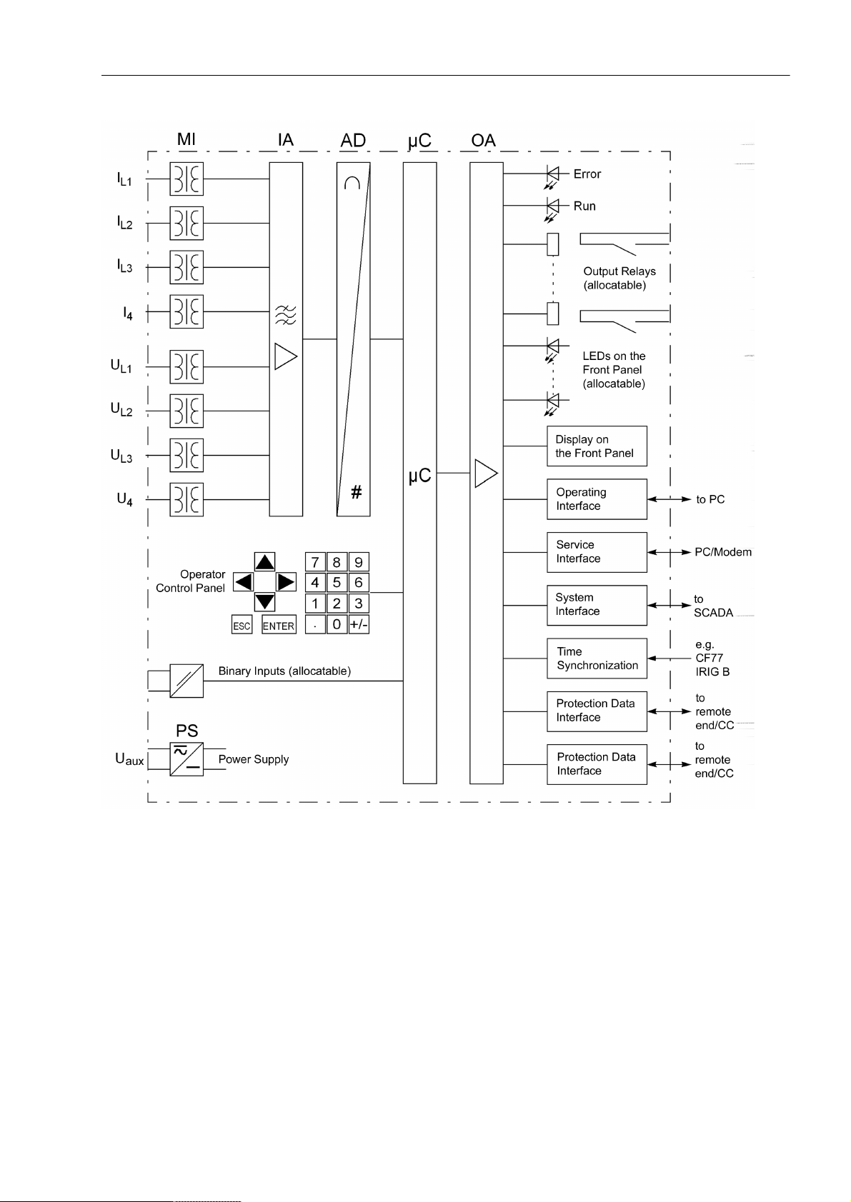
The digital Distance Protection SIPROTEC® 4 7SA522 is equipped with a powerful microprocessor system. This provides fully numerical processing of all functions in the
device, from the acquisition of the measured values up to the output of commands to
the circuit breakers Figure 1-1 shows the basic structure of the 7SA522.
Analog I n pu ts The measuring inputs (MI) convert the currents and voltages coming from the trans-
formers and adapt them to the level appropriate for the internal processing of the
device. The device has 4 current and 4 voltage inputs. Three current inputs are provided for measurement of the phase currents, a further measuring input (I
configured to measure the earth current (residual current from the current transformer
star-point), the earth current of a parallel line (for parallel line compensation) or the
star-point current of a power transformer (for earth fault direction determination).
) may be
4
18
7SA522 Manual
C53000-G1176-C155-3
Page 19
1.1 Overall Operation
Figure 1-1 Hardware structure of the digital Distance Protection 7SA522
A voltage measuring input is provided for each phase-earth voltage. A further voltage
input (U
) may optionally be used to measure either the displacement voltage (e-n volt-
4
age), for a busbar voltage (for synchronism and voltage check) or any other voltage
U
(for overvoltage protection). The analog values are transferred further to the IA
X
input amplifier group.
The input amplifier group IA provides high-resistance termination for the analog input
quantities. It consists of filters that are optimized for measured value processing with
regard to bandwidth and processing speed.
The AD analog digital converter group contains analog/digital converters and memory
components for data transfer to the microcomputer system.
7SA522 Manual
C53000-G1176-C155-3
19
Page 20

1 Introduction
Microcomputer System
Apart from processing the measured values, the microcomputer system µC also executes the actual protection and control functions. They especially consist of:
• Filtering and conditioning of the measured signals,
• Continuous monitoring of the measured quantities
• Monitoring of the pickup conditions for the individual protective functions
• Querying of limit values and time sequences,
• Control of signals for logical functions,
• Reaching trip and close command decisions,
• Stocking messages, fault data and fault values for fault analysis purposes,
• Administration of the operating system and its functions, e.g. data storage, realtime
clock, communication, interfaces, etc.
The information is provided via output amplifier OA.
Binary Inputs and Outputs
Binary inputs and outputs from and to the computer system are routed via the I/O
modules (inputs and outputs). The computer system obtains the information from the
system (e.g remote resetting) or the external equipment (e.g. blocking commands).
Additional outputs are mainly commands that are issued to the switching devices and
messages for remote signalling of events and states.
Front Elements LEDs and an LC display provide information on the function of the device and indicate
events, states and measured values.
Integrated control and numeric keys in conjunction with the LCD facilitate local inter-
action with the device. Thereby, all information on the device such as configuration
and setting parameters, operation and fault indications and measured values can be
retrieved or changed, (see also Chapter 2 and SIPROTEC
order no. E50417-H1176-C151.
Devices with control functions also allow station control on the front panel.
Serial Interfaces Via the serial inte rface
using the operating program DIGSI
dling of all device functions.
The service
using DIGSI
interface can also be used for communication with a personal computer
®
. This interface is especially well suited for the fixed wiring of the devices
to the PC or operation via a modem.
Via the serial system interface
tion unit or to a control centre. This interface may be provided with various protocols
and physical transmission schemes to suit the particular application.
A further interface is provided for time synchronization
ternal synchronization sources.
Further communication protocols can be realized via additional interface modules.
Protection Data Interface (optional)
Depending on the version there are one or two protection data interfaces
interfaces the data for the teleprotection scheme and further information such as
closing the local circuit breaker, other external trip commands coupled via binary
inputs and binary information can be transmitted to other ends.
®
4 System Description,
in the front panel the communication with a personal computer
®
is possible. This facilitates a comfortable han-
all device data can be transferred to a central evalua-
of the internal clock through ex-
. Via these
Power Supply These described functional units are supplied by a power supply PS with the neces-
sary power in the different voltage levels. Brief supply voltage dips which may occur
20
7SA522 Manual
C53000-G1176-C155-3
Page 21

1.1 Overall Operation
on short circuits in the auxiliary voltage supply of the power system are usually bridged
by a capacitor (see also Technical Data, Sub-section 4.1).
7SA522 Manual
C53000-G1176-C155-3
21
Page 22

1 Introduction
1.2 Application Scope
The digital distance protection SIPROTEC® 4 7SA522 is a selective and quick protection for overhead lines and cables with single- and multi-ended infeeds in radial, ring
or any type of meshed systems of any voltage levels. The network neutral can be
earthed, compensated or isolated.
The device incorporates the functions which are normally required for the protection
of an overhead line feeder and is therefore capable of universal application. It may
also be applied as time-graded back-up protection to all types of comparison protection schemes used on lines, transformers, generators, motors and busbars of all
voltage levels.
The devices located at the ends of the protected zone exchange measuring information via teleprotection functions with conventional connections (contacts) or via optional protection data interfaces using dedicated communication links (usually fibre optic
cables) or a communication network. If the 7SA522 devices are equipped with a protection data interface, they can be used for a protection object with 2 ends. Lines with
three terminals (teed feeders) require at least one device with two protection data interfaces.
Protective Elements
The basic function of the device is the recognition of the distance to the fault with distance protection measurement. In particular for complex multiphase faults, the distance protection has a non-switched 6-impedance-loops design (full scheme). Different pickup schemes enable a good adaption to system conditions and the user
philosophy. The network neutral can be isolated, compensated or earthed (with or
without earth current limiting). The use on long, heavily-loaded lines is possible with
or without series compensation.
The distance protection may be supplemented by teleprotection using various signal
transmission schemes (for fast tripping on 100 % of the line length). In addition, an
earth fault protection for high resistance earth faults (ordering option) is available,
which may be directional, non-directional and may also be incorporated in signal
transmission. On lines with weak or no infeed at one line end, it is possible to achieve
fast tripping at both line ends by means of the signal transmission schemes. Subsequent to energizing the line onto a fault which may be located along the entire line
length, it is possible to achieve a non-delayed trip signal.
In the event of a failure of the measured voltages due to a fault in the secondary circuits (e.g. trip of the voltage transformer mcb or a fuse) the device can automatically
revert to an emergency operation with an integrated overcurrent protection, until the
measured voltage again becomes available. This time overcurrent protection has
three definite-time overcurrent stages and one inverse-time stage; a number of characteristics based on various standards is available for the inverse-time stage. The
stages can be combined in any way. Alternatively, the time delayed overcurrent protection may be used as back-up time delayed overcurrent protection, i.e. it functions
independent and parallel to the distance protection.
22
Depending on the version ordered, most short-circuit protection functions may also trip
single-pole. They may work in co-o per ati on with an integrated automatic reclosure
(available as an option) which enables single-pole, three-pole or single and three-pole
automatic reclosure as well as several interrupt cycles on overhead lines. Before reclosure after three-pole tripping, the device can check the validity of the reclosure
through voltage and/or synchronism check (can be ordered optionally). It is also possible to connect an external automatic reclosure and/or synchronism check as well as
double protection with one or two automatic reclosure functions.
7SA522 Manual
C53000-G1176-C155-3
Page 23

1.2 Application Scope
Apart from the mentioned fault protection functions, additional protection functions are
possible, such as multi-stage overvoltage, undervoltage and frequency protection,
circuit breaker failure protection and protection against effects of power swings (simultaneously active as power swing blocking for the distance protection). For the rapid location of the damage to the line after a fault, a fault locator is integrated which also
may compensate the influence of parallel lines.
Digital Transmission of Protection
Data (optional)
If the distance protection is to be complemented by digital teleprotection schemes, the
data required for this purpose can be transmitted via the protection data interface by
employing a digital communication link. Communication via the protection data interfaces can be used for transmitting further information. Besides measured values also
binary commands or other information can be transmitted.
With more than two devices (= ends of the protected object) the communication can
be built up as a ring. This enables a redundant operation in case one communication
line fails. The devices will automatically find the remaining healthy communication
lines. But even with two ends, communication lines can be doubled to create redundancies.
Control Functions Depending on the ordered variant the device provides control functions which can be
accomplished for activating and deactivating switchgears via the integrated operator
panel, the system interface, binary inputs and a personal computer with the operating
software DIGSI
®
. The status of the primary equipment can be transmitted to the device
via auxiliary contacts connected to binary inputs. The current status (or position) of the
primary equipment can be read out at the device, and used for interlocking or plausibility monitoring. The number of the operating equipment to be switched is limited by
the binary inputs and outputs available in the device or the binary inputs and outputs
allocated for the switch position indications. Depending on the equipment used one
(single point indication) or two (double point indication) binary inputs may be used. The
capability of switching primary equipment can be restricted by a setting associated
with the switching authority (remote or local), and by the operating mode (interlocked/non-interlocked, with or without password request). Processing of interlocking
conditions for switching (e.g. switching error protection) can be established with the
aid of integrated, user-configurable logic functions.
Messages and Measured Value s; Fault
Recording
The operating messages provide information about conditions in the power system
and the device. Measurement quantities and values that are calculated can be displayed locally and communicated via the serial interfaces.
Device messages can be assigned to a number of LEDs on the front cover (allocatable), can be externally processed via output contacts (allocable), linked with user-definable logic functions and/or issued via serial interfaces (see Communication below).
During a fault (fault in the system) important events and status changes are stored in
the fault logs. Instantaneous fault values are also saved in the device and may be analyzed subsequently.
Co m mu n ic a t i on Serial interfaces are available for the communication with operating, control and
memory systems.
A 9-pin DSUB socket on the front cover is used for local communication with a person-
al computer. By means of the SIPROTEC
al and evaluation tasks can be executed via this operating
®
operating software DIGSI® 4, all operation-
interface, such as specifying and modifying configuration parameters and settings, configuration of userspecific logic functions, retrieving operational messages and measured values, inquiring device conditions and measured values, issuing control commands.
7SA522 Manual
C53000-G1176-C155-3
23
Page 24

1 Introduction
To establish an extensive communication with other digital operating, control and
memory components the device may be provided with further interfaces depending on
the order variant.
The service
interface can be operated through data lines. Also, a modem can be connected to this interface. For this reason, remote operation is possible via personal
computer and the DIGSI
®
operating software, e.g. to operate several devices via a
central PC.
The system
interface ensures the central communication between the device and the
substation controller. The service interface can be operated through data cables or
optical fibres. For data transmission there are several standardized protocols available. The integration of the devices into automation systems from other manufacturers
can also take place with this profile.
24
7SA522 Manual
C53000-G1176-C155-3
Page 25

1.3 Characteristics
General Features • Powerful 32-bit microprocessor system
• Complete di gi tal proces si ng of me as ur ed va lu es an d co nt r ol , fro m the sa mp li n g of
the analog input values up to the closing and tripping commands to the circuit
breakers
• Complete galvanic and reliable separation between internal processing circuits
from the measurement, control, and power supply circuits by analog input transducers, binary inputs and outputs and the DC/DC or AC/DC converters
• Complete scope of functions which are normally required for the protection of a line
feeder
• Digital protection data transmission, may be used for teleprotection with permanent
monitoring of disturbance, fault or transfer time deviations in the communication
network with automatic runtime re-adjustment
• Distance protection system realizable for 3 ends
• Simple device operation using the integrated operator panel or a connected personal computer with operator guidance
1.3 Characteristics
• Storage of fault indications as well as instantaneous values for fault recording
Distance Protection • Protection for all types of faults in systems with earthed, compensated or isolated
starpoint
• Selectable polygonal tripping characteristic or MHO-circle characteristic;
• Reliable differentiation between load and fault conditions also on long, high-loaded
lines
• High sensitivity in the case of a weakly loaded system, extreme stability against
load jumps and power swings
• Optimum adaption to the line parameters by means of the tripping characteristic
with diverse configuration parameters and “load trapezoid” (elimination of the possible load impedances);
• Six measuring systems for each distance zone
• Six distance zones, selectable as forward, reverse or non-directional reaching, one
may be used as an overreach zone
• Nine time stages for the distance zones
• Direction determination (with polygon) or polarisation (with MHO-circle) is done with
unfaulted loop (quadrature) voltages and voltage memory , thereby achieving unlimited directional sensitivity, and not affected by capacitive voltage transformer transients
7SA522 Manual
C53000-G1176-C155-3
• Suitable for lines with series compensation
• Insensitive to current transformer saturation
• Compensation against the influence of a parallel line
• Shortest tripping time is approx. 17 ms (for f
= 50 Hz) or 15 ms (for fN = 60 Hz)
N
• Phase segregated tripping (in conjunction with single-pole or single- and three-pole
auto-reclosure)
• Non-delayed tripping following switch onto fault
25
Page 26

1 Introduction
• Two sets of earth impedance compensation
Power Swing Supplement (optional)
Teleprotection Supplement
• Power swing detection with dZ/dt measurement with three measuring systems
• Power swing detection up to a maximum of 7 Hz swing frequency;
• In service also during single-pole dead times
• Settable power swing programs
• Prevention of undesired tripping by the distance protection during power swings
• Tripping for out-of-step conditions can also be configured
• Different procedures may be set:
• Permissive Underreach Transfer Trip = PUTT (via a separately settable overreach
zone);
• Comparison schemes (Permissive O verreach Transfer Trip = POTT or blocking
schemes, with separate overreach zone);
• Suitable for lines with two or three ends
• Phase segregated transmission possible in lines with two ends
• Optionally signal exchange of the devices via dedicated communication links (in
general optical fibres) or a communication network, in this case a phase-segregated transmission with two or three line ends and continuous monitoring of the communication paths and the signal propagation delay with automatic re-adjustment.
Earth Fault Protection (optional)
• Time overcurrent protection with maximally three definite time stages (DT) and one
inverse time stage (IDMT) for high resistance earth faults in earthed systems
• For inverse time protection a selection from various characteristics based on
several standards can be made
• The inverse time stage can also be set as fourth definite time stage
• High sensitivity (depending on the version from 3 mA);
• Phase current stabilization against fault currents during current transformer saturation
• Second harmonic inrush restraint
• Optionally earth fault protection with zero sequence voltage tripping time or inverse
time tripping
• Each stage can be set to be non-directional or directional in the forward or reverse
direction
• Single-pole tripping enabled by integrated phase selector
• Direction determination with automatic selection of the larger of zero sequence
voltage or negative sequence voltage (U
quantities (I
I
). or with negative sequence system quantities (I2, U2) or with zero sequence
Y
power (3I
, U0), with zero sequence current and transformer starpoint current (I0,
0
· 3U0);
0
, Iy or U2), with zero sequence system
0
• One or more stages may function in conjunction with a signal transmission supplement; also suited for lines with three ends
26
• Instantaneous tripping by any stage when switching onto a fault
7SA522 Manual
C53000-G1176-C155-3
Page 27

1.3 Characteristics
Transmission of Information (only
with numerical protection data transmission)
Tripping at Line Ends with no or Weak Infeed
External Direct and Remote Tripping
Time Overcurrent Protection
• Transmission of the measured values from all ends of the protected object
• Transmission of 4 commands to all ends
• Transmission of 24 additional binary signals to all ends
• Possible in conjunction with telepr otection schemes
• Allows fast tripping at both line ends, even if there is no or only weak infeed available at one line end
• Phase segregated tripping and single-pole automatic reclosure (version with singlepole tripping)
• Tripping at the local line end from an external device via a binary input
• Tripping of the remote line end by internal protection functions or an external device
via a binary input (with teleprotection)
• Selectable as emergency function in the case of measured voltage failure, or as
backup function independent of the measured voltage
• Maximally two definite time stages (DT) and one inverse time stage (IDMT), each
for phase currents and earth current
• For IDMT protection a selection from various characteristics based on several standards is possible
Instantaneous High-Current Switch-onto-Fault Protection
Automatic Reclosure Function (optional)
• Blocking capability e.g. for reverse interlocking with any element
• Instantaneous tripping by any stage when switching onto a fault
• Stub fault protection: Additional stage for fast tripping of faults between the current
transformer and line isolator (when the isolator switching status feed back is available); particularly suited to substations with 1
1
/2 circuit breaker arrangements.
• Fast tripping for all faults on total line length
• Selectable for manual closure or following each closure of the circuit breaker
• With integrated line energization detection
• For reclosure after single-pole, three-pole or single-pole and three-pole tripping
• Single or multiple reclosure (up to 8 reclosure attempts)
• With separate action times for every reclosure attempt, optionally without action
times
• With separate dead times after single-pole and three-pole tripping, separate for the
first four reclosure attempts
• Controlled optionally by protection pickup with separate dead times after single,
two-pole and three-pole pickup
• Optionally with adaptive dead time, reduced dead time and dead line check.
Synchronism and
Voltage Check (optional)
7SA522 Manual
C53000-G1176-C155-3
• V eri f ic at i on of th e synchronous con d it i ons b ef o re re clo sing after th re e- po l e t rip p in g
• Fast measuring of voltage difference U
quency difference f
diff
;
of the phase angle difference ϕ
diff
and fre-
diff
27
Page 28

1 Introduction
• Alternatively, check of the de-energized state before reclosing
• Closing at asynchronous system conditions with prediction of the synchronization
time
• Settable minimum and maximum voltage
• Verification of the synchronous conditions or de-energized state also possible
before the manual closing of the circuit breaker, with separate limit values
• Also measurement via transformer
• Measuring voltages optionally phase-phase or phase-earth
Voltage Protection (optional)
Frequency Protection (optional)
• Overvoltage and undervoltage detection with different stages
• Two overvoltage stages for the phase-earth voltages, with common time delay
• Two overvoltage stages for the phase-phase voltages, with common time delay
• Two overvoltage stages for the positive sequence voltage, with a time delay each,
optionally with compounding
• Two overvoltage stages for the negative sequence voltage, with a time delay each
• Two overvoltage stages for the zero sequence voltage or any other single-phase
voltage, with a time delay each
• Settable drop-off to pick-up ratios for the overvoltage protection functions
• Two undervoltage stages for the phase-earth voltages, with common time delay
• Two undervoltage stages for the phase-phase voltages, with common time delay
• Two undervoltage stages for the positive sequence voltage, with a time delay each
• Settable current criterion for undervoltage protection functions
• Monitoring on underfrequency (f<) and/or overfrequency (f>) with 4 frequency limits
and delay times that are independently adjustable
• Very insensitive to phase angle changes
• Large frequency range (approx. 25 Hz to 70 Hz)
Fault Location • Initiated by trip command or reset of the pickup
• Computation of the distance to fault with dedicated measured value registers
• Fault location output in ohm, kilometers or miles and % of line length
• Parallel line compensation can be selected
• Taking into consideration the load current in case of single-phase earth faults fed
from both sides (settable)
Circuit Breaker Failure Protection (optional)
• With definite time current stages for monitoring current flow through every pole of
the circuit breaker
• With definite time monitoring time steps for single-pole and three-pole tripping
• Start by trip command of every internal protection function
• Start by external trip functions possible
• Single-stage or two-stage
28
7SA522 Manual
C53000-G1176-C155-3
Page 29

• Short dropout and overshoot times
1.3 Characteristics
User-defined Functions
Commissioning;
Operation (only
with digital transmission of protection data)
Command Processing
Monitoring Functions
• Freely programmable combination of internal and external signals for the implementation of user-defined logic functions;
• All common logic functions
• Time delays and set point interrogation
• Display of magnitude and phase angle of local and remote measured values
• Display of measured values of the communication link, such as runtime and availability
• Switchgears can be energized and de-energized manually via local control keys,
the programmable function keys on the front panel, via the system interface (e.g. by
SICAM
operating software DIGSI
®
or LSA), or via the operating interface using a personal computer and the
®
)
• Feedback on switching states via the circuit breaker auxiliary contacts (for commands with feedback)
• Plausibility monitoring of the circuit breaker position and monitoring of interlocking
conditions for switchi ng ope ra tio ns
• Availability of the device is greatly increased by monitoring of the internal measurement circuits, auxiliary power supply, hardware, and software
Additional Functions
• Current transformer and voltage transformer secondary circuits are monitored
using summation and symmetr y check techniques
• Trip circuit supervision
• Checking for the load impedance, the measured direction and the phase sequence
• Monitoring the signal transmission of the optional digital communication path
• Battery buffered real time clock, which may be synchronized via a synchronization
signal (e.g. DCF77, IRIG B via satellite receiver), binary input or system interface
• Continuous calculation and display of measured quantities on the front display. Indication of measured values of the remote end or of all ends (for devices with protection data interfaces);
• Fault event memory (trip log) for the last 8 network faults (faults in the power system), with real time stamps
• Fault recording and data transfer for fault recording for a maximum time range of
15 s
• Statistics: Counter with the trip commands issued by the device, as well as recording of the fault current data and accumulation of the interrupted fault currents
• Communication with central control and memory components possible via serial interfaces (depending on the individual ordering variant), optionally via data line,
modem or fibre optics
7SA522 Manual
C53000-G1176-C155-3
29
Page 30

1 Introduction
• Commissioning aids such as connection and direction checks as well as circuit
breaker test functions
■
30
7SA522 Manual
C53000-G1176-C155-3
Page 31

Functions 2
This chapter describes the numerous functions available on the SIPROTEC® 4
7SA522. It shows the setting possibilities for all the functions in maximum configuration. Instructions for deriving setting values and formulae, where required are
provided.
Additionally it may be defined which functions are to be used.
2.1 General 32
2.2 Distance protection 62
2.3 Power swing detecti on (optiona l) 108
2.4 Protection data interfaces and communication topology (optional) 115
2.5 Remote signals via protection data interface (optional) 124
2.6 Teleprotection for distance protection 127
2.7 Earth fault overcurrent protection in earthed systems (optional) 151
2.8 Teleprotection for earth fault overcurrent protection (optional) 176
2.9 Weak-infeed tripping 196
2.10 External direct and remote tripping 206
2.11 Overcurrent protection 208
2.12 Instantaneous high-current switch-on-to-fault protection (SOTF) 224
2.13 Automatic reclosure function (optional) 227
2.14 Synchronism and voltage check (optional) 259
2.15 Undervoltage and overvoltage protection (optional) 271
2.16 Frequency protection (optional) 288
2.17 Fault locat o r 294
2.18 Circuit breaker failure protection (optional) 299
2.19 Monitoring function 314
2.20 Function control and circuit breaker testing 330
2.21 Auxiliary functions 346
2.22 Command pr oces si ng 362
C53000-G1176-C155-3
317SA522 Manual
Page 32

2 Functions
2.1 General
A few seconds after the device is switched on, the initial display appears in the LCD.
Configuration of the device functions are made via the DIGSI
The procedure is described in detail in the SIPROTEC
No. E50417-H1176-C151. Entry of password No. 7 (for setting modification) is required to modify configuration settings. Without the password, the settings may be
read, but may not be modified and transferred to the device.
The function parameters, i.e. settings of function options, threshold values, etc., can
be entered via the keypad and display on the front of the device, or by means of a personal computer connected to the front or service interface of the device utilising the
®
DIGSI
2.1.1 Functional Scope
2.1.1.1 Configuration of the Functional Scope
software package. The level 5 password (individual parameters) is required.
®
®
software from your PC.
4 System Descript ion , Or de r
The 7SA522 relay contains a series of protective and additional functions. The hard-
ware and firmware provided is designed for this scope of functions. In addition the
command functions can be matched to the system conditions. Individual functions can
be activated or deactivated during the configuration procedure. The interaction of
functions may also be modified.
Example
for the configuration of functional scope:
A substation has overhead line and transformer feeders. Y ou want to perform fault location on overhead lines only. For the devices on the transformer feeders you therefore “suppress” this function during configuration.
The available protective and additional functions must be configured as (QDEOHG or
'LVDEOHG. For some functions a choice between several alternatives is possible, as
described below.
Functions configured as 'LVDEOHG are not processed by the 7SA522. There are no
indications, and corresponding settings (functions, limit values) are not displayed
during setting.
Note
The functions and default settings available depend on the order variant of the device.
2.1.1.2 Setting Notes
Configuration of Function Scope
32
Configuration settings can be entered using a PC and the software program DIGSI
and transferred via the operating interface on front cover of the device or via the
service interface. Operation using DIGSI
®
is described in the SIPROTEC®4 System
Description, Order No. E50417-H1176-C151.
7SA522 Manual
C53000-G1176-C155-3
®
Page 33

For changing configuration parameters in the device, password no.7 is required (for
parameter set). Without the password, the settings may be read, but may not be modified and transmitted to the device.
The functional scope with the available options is set in the Device Configuration
dialog box to match system requirements.
Special Cases Most settings are self-explanatory. The special cases are described below.
For communication of the protection signal each device may feature one or two protection data interfaces (depending on the ordered version). Determine at address
whether to use protection data interface 3,17(5)$&( or at address 3
,17(5)$&(. A protected object with two ends requires at least one protection data
interface for each relay. If there is more than one end, it must be ensured that all associated devices are connected directly or indirectly (via other devices). Subsection
2.4 “Communication Topology” provides more information.
If use of the setting group change function is desired, address *US&KJH
237,21 should be set to (QDEOHG. In this case, up to four different groups of settings
may be changed quickly and easily during device operation (see also Subsection
2.1.4). Only one setting group may be selected and used if the setting is 'LVDEOHG.
Address 7ULSPRGH is only valid for devices that trip single-pole or three-pole.
Set SROH to enable also single-pole tripping i.e., if you want to utilize single-pole
or single-pole / multi-pole automatic reclosure. This requires an internal automatic reclosing function to be available or an external reclosing device. Furthermore, the
circuit breaker must be capable of single pole tripping.
2.1 General
Note
If you have changed address , save your changes first via OK and reopen the
dialog box since the other setting options depend on the selection in Address .
Depending on the model of the distance protection, you can select the tripping characteristic it should use at address for the phase-to-phase measuring systems
3KDVH'LVWDQFH and at address for the phase-to-earth measuring systems
(DUWK'LVWDQFH. You can select between the polygonal tripping characteristic
4XDGULODWHUDO and the MHO-circle characteristic 0+2. Subsection 2.2.3 and 2.2.2
provide a detailed overview of the characteristics and measuring methods. The two
addresses can be set separately and differently. If you want to use the relay only for
phase-to-earth loops, the function not required is set 'LVDEOHG. If the relay features
only one of the characteristics, the corresponding addresses are not visible.
T o complement the distance protection by teleprotection schemes, you can select the
desired scheme at address 7HOHSURW'LVW. Y ou can select the underreach
transfer trip with overreach zone 3877=%, the teleprotection scheme 3277, the
unblocking scheme 81%/2&.,1* and the blocking scheme %/2&.,1*. If the device
features a protection data interface for communication via digital transmission lines,
set 6,*1$/Y3URW,QW here. The procedures are described in detail in Section 2.2.1.
If you don’t want to use teleprotection in conjunction with distance protection set
'LVDEOHG.
The power swing supplement (see also Subsection 2.3) is activated by setting address
3RZHU6ZLQJ = (QDEOHG.
7SA522 Manual
C53000-G1176-C155-3
With address :HDN,QIHHG you can select a supplement to the teleprotection
schemes. S et (QDEOHG to apply the classic scheme for echo and weak infeed tripping.
33
Page 34

2 Functions
The setting /RJLFQR switches this function to the French specification. This
setting is available in the device variants for the region France (only version
7SA522*-**D** or 10th digit of order number = D).
At Address %DFN8S2& you can select the type of characteristic which the time
overcurrent protection uses for operation. In addition to the definite time overcurrent
protection, an inverse time overcurrent protection may be configured depending on
the ordered version. The latter operates either according to an IEC-characteristic (72&
,(&) or an ANSI-characteristic (72&$16,). For the characteristics please refer to the
Technical Data. You can also disable the time overcurrent protection ('LVDEOHG).
At address (DUWK)DXOW2& you can select the type of characteristic which
the earth fault protection uses for operation. In addition to the definite time overcurrent
protection, which provides up to three stages, an inverse-time earth fault protection
function may be configured depending on the ordered version. The latter operates
either according to an IEC-characteristic (72&,(&) or an ANSI-characteristic (72&
$16,) or according to a logarithmic-inverse characteristic (72&/RJDULWKP). If an
inverse-time characteristic is not required, the stage usually designated “inverse time”
can be used as the fourth definite-time stage ('HILQLWH7LPH). Alternatively, it is
possible to select an earth fault protection with inverse-time characteristic 8
LQYHUVH (only for region German, 10th digit of the ordering code = A) or a zero-sequence power protection 6ULQYHUVH (only for region French, 10th digits of ordering
code = D). For the characteristics please refer to the Technical Data. You can also
disable the earth fault protection ('LVDEOHG).
When using the earth fault protection, it can be complemented by teleprotection
schemes. Select the desired scheme at address 7HOHSURW(). You can
select the direction comparison scheme 'LU&RPS3LFNXS, the unblocking scheme
81%/2&.,1* and the blocking scheme %/2&.,1*. The procedures are described in
detail in Section 2.8. If the device features a protection data interface for communication via a digital link, set 6,*1$/Y3URW,QW here. If you do not want to use teleprotection in conjunction with earth fault protection set 'LVDEOHG.
Address 3,17(5)$&( and , w her e re quir ed , ad dr ess 3,17(5)$&(
are also valid for communication of the teleprotection for earth fault protection via
teleprotection interface, as described above.
If the device features an automatic reclosing function, address and are of importance. If no automatic reclosing function is desired for the feeder at which 7SA522
operates, or if an external device is used for reclosure, set address $XWR
5HFORVH to 'LVDEOHG. Automatic reclosure is only allowed on overhead lines. It
should not be used in any other case. If the protected object consists of a mixture of
overhead lines and other equipment (e.g. overhead line in block with a transformer or
overhead line/cable), it must be ensured that reclosure can only be performed in the
event of a fault on the overhead line.
Otherwise set the number of desired reclosing attempts there. You can select $5
F\FOH to $5F\FOHV. Y ou can also set $'7 (adaptive dead times). In this case the
behaviour of the automatic reclosing function is determined by the cycles of the
remote end. The number of cycles must however be configured at least in one of the
line ends which must have a reliable infeed. The other end — or other ends, if there
are more than two line ends — may operate with adaptive dead time. Section 2.13 provides detailed information on this topic.
34
The $5FRQWUROPRGH at address allows a maximum of four options. Firstly, it
can be determined whether the auto-reclose cycles are carried out according to the
fault type detected by pickup of the starting protective function(s) (only three-pole tripping), or according to the type of trip command. Secondly, the automatic reclosing
function can be operated with or without action time.
7SA522 Manual
C53000-G1176-C155-3
Page 35

2.1 General
The setting 7ULSZLWK7DFWLRQ7ULSZLWKRXW7DFWLRQ (default
setting = Trip with T-action ...) is preferred if single-pole
or single-pol e/thre e-pole au toreclose cycles are provided for and possible. In this case different dead times after
single-pole tripping on the one hand and after three-pole tripping on the other hand are
possible (for every reclose cycle). The protective function that issues the trip
command determines the type of trip: single-pole or three-pole. Depending on the
latter the dead time is selected.
The setting 3LFNXSZLWK7DFWLRQ3LFNXSZLWKRXW7DFWLRQ
(Pickup with T-action ...) is only possible and visible if only three-pole tripping is desired. This is the case when either the ordering number of the device model indicates
that it is only suited for three-pole tripping, or when only three-pole tripping is configured (address 7ULSPRGH = SROHRQO\, see above). In this case you can set
different dead times for the auto-reclose cycles following single-pole
three-pole
faults. The decisive factor here is the pickup situation of the protective
, two-pole and
functions at the instant the trip command disappears. This control mode enables also
the dead times to be made dependent on the type of fault in the case of three-pole
reclosure cycles. Tripping is always three-pole.
The setting 7ULSZLWK7DFWLRQ provides an action time for each reclose cycle.
The action time is started by a general pickup of all protection functions. If no trip
command is present before the action time expires, the corresponding reclose cycle
is not carried out. Section 2.13 provides detailed information on this topic. This setting
is recommended for time-graded protection. If the protection function which is to
operate with automatic reclosure, does not have a general pickup signal for starting
the action times, select 7ULSZLWKRXW7DFWLRQ.
Address allows the voltage protection function to be activated using various undervoltage and overvoltage elements. Particularly, the overvoltage protection with the
positive sequence system of the measured voltages provides the option to calculate
the voltage at the other line end via integrated compounding. This is particularly useful
for long transmission lines where no-load or low-load conditions prevail and an overvoltage at the other line end (Ferranti effect) is to cause tripping of the local circuit
breaker. In this case set address 8292/7$*( to (QDEOZFRPS (available
with compounding). Do not use compounding in lines with series capacitors!
The fault location can be set at address )DXOW/RFDWRU to (QDEOHG or
'LVDEOHG.
For the trip circuit supervision set at address 7ULS&LU6XS the number of
trip circuits to be monitored: WULSFLUFXLW, WULSFLUFXLWV or WULS
FLUFXLWV, unless you omit it ('LVDEOHG).
2.1.1.3 Settings
Addr. Parameter Setting Options Default Setting Comments
103 Grp Chge OPTION Disabled
Enabled
110 Trip mode 3pole only
1-/3pole
112 Phase Distance Quadrilateral
MHO
Disabled
Disabled Setting Gr oup Change Opt ion
3pole only Trip mode
Quadrilateral Phase Distance
7SA522 Manual
C53000-G1176-C155-3
35
Page 36

2 Functions
Addr. Parameter Setting Options Default Setting Comments
113 Earth Distance Quadrilateral
MHO
Disabled
120 Power Swing Disabled
Enabled
121 Teleprot. Dist . PUTT (Z1B)
POTT
UNBLOCKING
BLOCKING
SIGNALv.ProtInt
Disabled
122 DTT Direct Trip Disabled
Enabled
124 SOTF Overcurr. Disabled
Enabled
125 Weak Infeed Disabled
Enabled
Logic no. 2
126 Back-Up O/C Disabl ed
TOC IEC
TOC ANSI
131 Earth Fault O/C Disabled
TOC IEC
TOC ANSI
TOC Logarithm.
Definite Time
U0 inverse
Sr inverse
132 Teleprot. E/F Dir.Co mp. Picku p
SIGNALv.ProtInt
UNBLOCKING
BLOCKING
Disabled
133 Auto Reclose 1 AR-cycle
2 AR-cycles
3 AR-cycles
4 AR-cycles
5 AR-cycles
6 AR-cycles
7 AR-cycles
8 AR-cycles
ADT
Disabled
134 AR control mode Pickup w/ Tact
Pickup w/o Tact
Trip w/ Tact
Trip w/o Tact
135 Synchro-Check Disabled
Enabled
136 FREQUENCY Prot. Disabled
Enabled
137 U/O VOLTAGE Disabled
Enabled
Enabl. w. comp.
Quadrilateral Earth Distance
Disabled Power Swing detection
Disabled Teleprotection for Distance prot.
Disabled DTT Direct Transfer Trip
Disabled Instantaneous HighSpeed SOTF
Overcurrent
Disabled Weak Infeed (Trip and/or Echo)
TOC IEC Backup overcurrent
Disabled Earth fault overcurrent
Disabled Teleprotection for Earth fault over-
curr.
Disabled Auto-Reclose Function
Trip w/ Tact Auto-Reclose control mode
Disabled Synchronism and Voltage Check
Disabled Over / Underfrequency Protection
Disabled Under / Overvoltage Protection
36
7SA522 Manual
C53000-G1176-C155-3
Page 37

Addr. Parameter Setting Options Default Setting Comments
138 Fault Locator Enabled
Disabled
139 BREAKER FAILURE Disabled
Enabled
140 Trip Cir. Sup. Disabled
1 trip circuit
2 trip circuits
3 trip circuits
145 P. INTERFACE 1 Enabled
Disabled
146 P. INTERFACE 2 Disabled
Enabled
147 NUMBER OF RELAY 2 relays
3 relays
Enabled Fault Locator
Disabled Breaker Failure Protection
Disabled Trip Circuit Supervision
Enabled Protection Interface 1 (Port D)
Disabled Protection Interface 2 (Port E)
2 relays Number of relays
2.1.2 Device
The device requires some general information. This may be, for example, the type of
annunciation to be issued in the event a power system fault occurs.
2.1 General
2.1.2.1 Trip Dependent Messages
The indication of messages masked to local LEDs, and the maintenance of spontane-
ous messages, can be made dependent on whether the device has issued a trip
signal. This information is not output if one or more protection functions have picked
up due to a fault, but the 7SA522 has not initiated the tripping because the fault was
cleared by another device (e.g. on another line). These messages are then limited to
faults on the protected line.
The following figure illustrates the creation of the reset command for stored messages.
When the relay drops off, stationary conditions (fault display Target on PU / Target on
TRIP; Trip / No Trip) decide whether the new fault will be stored or reset.
Figure 2-1 Creation of the reset command for the latched LED and LCD messages
2.1.2.2 Spontaneous Annunciations on the Display
You can determine whether or not the most important data of a fault event are dis-
played automatically after the fault has occurred (see also Subsection “Fault Events”
in Section 2.21.1 “Additional functions”).
7SA522 Manual
C53000-G1176-C155-3
37
Page 38

2 Functions
2.1.2.3 Setting Notes
Fault Annunciations
Pickup of a new protective function generally turns off any previously lit LEDs, so that
only the latest fault is displayed at any time. It can be selected whether the stored LED
displays and the spontaneous annunciations on the display appear upon renewed
pickup, or only after a renewed trip signal is issued. In order to enter the desired type
of display, select the submenu General Device Settings in the SETTINGS menu. At
address )OW'LVS/('/&' the two alternatives 7DUJHWRQ38 and 7DUJHW
RQ75,3 (“No trip - no flag”) are offered.
For devices with graphical display use parameter 6SRQW)OW'LVS to specify
whether or not a spontaneous annunciation will appear automatically on the display
(<(6) or not (12). For devices with text display such messages will appear after a
system fault in any case.
After startup of a device featuring a 4-line display, measured values are displayed by
default. Use the arrow keys on the device front to select the different represenations
of the measured values for the so-called default display. The start page of the default
display, which is displayed by default after startup of the device, can be selected via
parameter 6WDUWLPDJH''. The available representation types for the measured values are listed in the appendix .
2.1.2.4 Settings
Addr. Parameter Setting Options Default Setting Comments
610 FltDisp.LED/LCD Target on PU
Target on TRIP
615 Spont. FltDisp. NO
YES
640 Start image DD image 1
image 2
image 3
image 4
image 5
Target on PU Fault Display on LED / LCD
NO Spontaneous display of flt.annun-
image 1 Start image Default Display
2.1.2.5 Information List
No. Information Type of In-
formation
- Test mode IntSP Test mode
- DataSto p IntSP Stop data transmission
- SynchC lock IntSP_Ev Clock Sync hronization
- >Light on SP >Back Light on
- HWTestMod IntSP Hardware Test Mode
- Error FMS1 OUT Error FMS FO 1
- Error FMS2 OUT Error FMS FO 2
- Brk OPENED IntSP Breaker OPENED
- FdrEARTHED IntSP Feeder EARTHED
1 Not configured SP No Function configured
ciations
Comments
38
7SA522 Manual
C53000-G1176-C155-3
Page 39

2.1 General
No. Information Type of In-
Comments
formation
2 Non Existent SP Function Not Available
3 >Time Synch SP >Synchronize Internal Real Time Clock
5 >Reset LED SP >Reset LED
11 >Annunc. 1 SP >User defined annunciation 1
12 >Annunc. 2 SP >User defined annunciation 2
13 >Annunc. 3 SP >User defined annunciation 3
14 >Annunc. 4 SP >User defined annunciation 4
15 >Test mode SP >Test mode
16 >DataStop SP >Stop data transmission
51 Device OK OUT Device is Operational and Protecting
52 ProtActive IntSP At Least 1 Protection Fun ct. is Active
55 Reset Device OUT Reset Device
56 Initial Start OUT Initial Start of Device
60 Reset LED OUT_Ev Reset LED
67 Resume OUT Resume
68 Clock SyncError OUT Clock Synchronization Error
69 DayLightSavTime OUT Daylight Saving Time
70 Settings Calc. OUT Setting calculation is running
71 Settings Check OUT Settings Check
72 Level-2 change OUT Level-2 change
73 Local change OUT Local setting change
110 Event Lost OUT_Ev Event lost
113 Flag Lost OUT Flag Lost
125 Chatter ON OUT Chatter ON
126 ProtON/OFF IntSP Protection ON/OFF (via system port)
127 AR ON/OFF IntSP Auto Reclose ON/OFF (via system port)
128 TelepONof f IntSP Teleprot. ON/OFF (via syste m port)
140 Error Sum Alarm OUT Error with a summary alarm
144 Error 5V OUT Error 5V
160 Alarm Sum Event OUT Alarm Summary Event
177 Fail Battery OUT Failure: Battery empty
181 Error A/D-conv. OUT Error: A/D converter
182 Alarm Clock OUT Alarm: Real Time Clock
183 Error Board 1 OUT Error Board 1
184 Error Board 2 OUT Error Board 2
185 Error Board 3 OUT Error Board 3
186 Error Board 4 OUT Error Board 4
187 Error Board 5 OUT Error Board 5
188 Error Board 6 OUT Error Board 6
189 Error Board 7 OUT Error Board 7
190 Error Board 0 OUT Error Board 0
191 Error Offset OUT Error: Offset
192 Error1A/5Awrong OUT Error:1A/5Ajumper different from setting
193 Alarm NO calibr OUT Alarm: NO calibration data available
194 Error neutralCT OUT Error: Neutral CT different from MLFB
4051 Telep. ON IntSP Teleprotection is switched ON
7SA522 Manual
C53000-G1176-C155-3
39
Page 40

2 Functions
2.1.3 Power System Data 1
The device requires certain system and power system data so that it can adapt the
implemented functions according to this data. This comprises e.g. nominal system
data, nominal data of instrument transformers, polarity and connection type of measured values, in certain cases circuit breaker properties, etc. Furthermore, there are
a number of settings associated with all functions rather than a specific protection,
control or monitoring function. These data can only be changed from a PC running
®
DIGSI
2.1.3.1 Setting Notes
General In DIGSI
CT's, VT's, Power System and Breaker will open under 3RZHU6\VWHP'DWD in
which you can configure the individual parameters. Thus, the following subsections
are structured accordingly.
and are discussed in this Subsection.
®
double-click Settings to display the available data. A dialog box with tabs
Current Transformer Polarity
Nominal Values of the Transformers
At address &76WDUSRLQW, the polarity of the wye-connected current transformers is specified (the following figure also goes for two current transformers). This
setting determines the measuring direction of the device (forwards = line direction).
Modifying th is set ting a lso res ult s in a pola rity r evers al of t he eart h curr ent inp uts I
I
.
EE
Figure 2- 2 Po larity of Cur rent Transformers
E
or
In addresses 8QRP35,0$5< and 8QRP6(&21'$5< the devic e obt ai ns in -
formation on the primary and secondary rated voltage (phase-to-phase voltage) of the
voltage transformers.
40
It is important to ensure that the rated secondary current of the current transformer
matches the rated current of the device, otherwise the device will incorrectly calculate
primary amperes.
The correct primary data are required for the calculation of the proper primary information of the operational measured values. If the settings of the device are performed
with primary values using DIGSI
®
, these primary data are an indispensable require-
ment for the fault-free operation of the device.
7SA522 Manual
C53000-G1176-C155-3
Page 41

2.1 General
Voltage Connection The device features four voltage measuring inputs, three of which are connected to
the set of voltage transformers. Various possibilities exist for the fourth voltage input
U
:
4
• Connect the U
input to the open delta winding e–n of the voltage transformer set:
4
Address is then set to: 8WUDQVIRUPHU = 8GHOWDWUDQVI.
When connected to the e-n winding of a set of voltage transformers, the voltage
transformation ratio of the voltage transformers is usually:
The factor Uph/Udelta (secondary voltage, address 8SK8GHOWD) must be
set to 3/√3
= √3 ≈ 1.73 . For other transformation ratios, i.e. the formation of the displacement voltage via an interconnected transformer set, the factor must be corrected accordingly. This factor is of importance if the 3U
>-protective element is
0
used and for the monitoring of the measured values and the scaling of the measurement and disturbance recording signals.
• Connection of the U
input to the busbar voltage in order to perform the synchro-
4
nism check:
Address is then set to: 8WUDQVIRUPHU = 8V\QFWUDQVI.
If the transformation ratio differs from that of the line voltage transformers, this can
be adapted with the setting in address 8OLQH8V\QF. In address
8V\QFFRQQHFW, the busbar voltage used for synchronism check is configured.
The device then selects automatically the appropriate feeder voltage. If the two
measuring points used for synchronism check — i.e. feeder voltage transformer
and busbar voltage transformer — are not separated by devices that cause a relative phase shift, then the parameter in address ϕ8V\QF8OLQH is not required. This setting is only possible via DIGSI
®
at "Additional Settings". If however
a power transformer is switched in between, its vector group must be considered.
The phase angle from U
line
to U
is evaluated positively.
2bus
Example
: (see also Figure 2-3)
Busbar 400 kV primary,
110 V secondary,
Feeder 220 kV primary,
100 V secondary,
Transformer 400 kV/220°kV,
Vector group Yd(n) 5
The transformer vector group is defined from the high side to the low side. In this
example, the feeder voltage is connected to the low voltage side of the transformer.
If Usync (busbar or high voltage side) is placed at zero degrees, then Uline is at 5
x 30° (according to the vector group) in the clockwise direction, i.e. at –150°. A positive angle is obtained by adding 360°:
Address : ϕ8V\QF8OLQH = 360° - 150° = 210°.
The busbar transformers supply 110 V secondary for primary operation at nominal
value while the feeder transformer supplies 100 V secondary . Therefore, this difference must be balanced:
Address : 8OLQH8V\QF = 100 V/110 V = 0.91.
7SA522 Manual
C53000-G1176-C155-3
41
Page 42

2 Functions
Figure 2-3 Busbar voltage measured via transformer
• Connection of the U
- input to any other voltage signal UX, which can be proces sed
4
by the overvoltage protection function:
Address is then set to: 8WUDQVIRUPHU = 8[WUDQVIRUPHU.
• If the input U
is not required, set:
4
Address 8WUDQVIRUPHU = 1RWFRQQHFWHG.
Also in this case the factor 8SK8GHOWD (Address , see above) is of impor-
tance, as it is utilised for the scaling of the measurement and disturbance recording
data.
Current Connection The device has four measured current inputs, three of which are connected to the
current transformer set. The fourth current measuring input I
may be utilised in
4
various ways:
• Connection of the I
input to the earth current in the starpoint of the set of current
4
transformers on the protected feeder (normal connection):
Address is then set to: ,WUDQVIRUPHU = ,QSURWOLQH and address
,,SK&7 = 1.
• Connection of the I
input to a separate earth current transformer on the protected
4
feeder (e.g. a summation CT or core balance CT):
Address is then set to: ,WUDQVIRUPHU = ,QSURWOLQH and address
,,SK&7 is set:
This is independent of whether the device has a normal measuring current input for
I
or a sensitive measuring current input.
4
42
7SA522 Manual
C53000-G1176-C155-3
Page 43

2.1 General
Example:
Phase current transformers 500 A/5 A
Core balance CT 60 A/1 A
• Connection of the I
input to the earth current of a parallel line (for parallel line com-
4
pensation of the distance protection and/or fault location):
Address is then set to: ,WUDQVIRUPHU = ,QSDUDOOLQH and usually
address ,,SK&7 = 1.
If the set of current transformers on the parallel line however has a different trans-
formation ratio to those on the protected line, this must be taken into account in
address :
Address is then set to: ,WUDQVIRUPHU = ,QSDUDOOLQH and address
,,SK&7 = I
N paral. line
/ I
N prot. line
Example:
Current transformers on protected line 1200 A
Current transformers on parallel line 1500 A
• Connection of the I
input to the starpoint current of a transformer; this connection
4
is occasionally used for the polarisation of the directional earth fault protection:
Address is then set to: ,WUDQVIRUPHU = ,<VWDUSRLQW, and address
,,SK&7 is according to transformation ratio of the starpoint transformer to the
transformer set of the protected line.
• If the I
input is not required, set:
4
Address ,WUDQVIRUPHU = 1RWFRQQHFWHG,
Address ,,SK&7 is then irrelevant.
In this case, the neutral current is calculated from the sum of the phase currents.
Rated Frequency The nominal frequency of the system is set in address 5DWHG)UHTXHQF\. The
presetting according to the ordering code (MLFB) only needs to be changed if the
device is applied in a region different to the one indicated when ordering. You can set
+] or +].
System Starpoint The manner in which the system starpoint is earthed must be considered for the
correct processing of earth faults and double earth faults. Accordingly, set for address
6\VWHP6WDUSRLQW = 6ROLG(DUWKHG, 3HWHUVRQ&RLO or ,VRODWHG. For
low-resistant earthed systems set 6ROLG(DUWKHG.
Phase Rotation Use address 3+$6(6(4 to change the default setting (/// for clockwise
rotation) if your power system has a permanent anti-clockwise phase sequence (/
//).
Distance Unit Address 'LVWDQFH8QLW determines the distance unit (NP or 0LOHV) for the
fault location indications. This parameter is not relevant if fault detection is not available. Changing the distance unit will not result in an automatic conversion of the
7SA522 Manual
C53000-G1176-C155-3
43
Page 44

2 Functions
setting values which depend on this distance unit. They have to be re-entered into their
corresponding valid addresses.
Mode of Earth Impedance (Residual)
Compensation
Operating Time of the Circuit Breaker
Trip Signal Duration
Matching of the earth to line impedance is an essential prerequisite for the accurate
measurement of the fault distance (distance protection, fault locator) during earth
faults. In address )RUPDW== the format for entering the residual compensation is determined. It is possible to either use the ratio 5(5/;(;/ or to enter
the complex earth (residual) impedance factor .. The actual setting of the earth (residual) impedance factors is done in the power system data 2 (refer to Section 2.1.5).
The circuit breaker closing time 7&%FORVH at address is required if the d evice
is to close also under asynchronous system conditions, no matter whether for manual
closing, for automatic reclosing after three-pole tripping, or both. The device will then
calculate the time for the close command such that the voltages are phase-synchronous the instant the breaker poles make contact.
In address the minimum trip command time 70LQ75,3&0' is set. This setting
applies to all protective functions that initiate tripping. It also determines the length of
the trip pulse when a circuit breaker trip test is initiated via the device. This setting is
only possible via DIGSI
®
at "Additional Settings".
In address the maximum close command duration 70D[&/26(&0' is set. This
applies to all close commands issued by the device. It also determines the length of
the close command pulse when a circuit breaker test cycle is issued via the device. It
must be set long enough to ensure that the circuit breaker has securely closed. There
is no risk in setting this time too long, as the close command will in any event be terminated following a new trip command from a protection function. This setting is only
possible via DIGSI
®
at "Additional Settings".
Circuit Breaker Test 7SA522 allows a circuit breaker test during operation by means of a tripping and a
®
closing command entered on the front panel or via DIGSI
. The duration of the trip
command is set as explained above. Address 7&%WHVWGHDG determines the
duration from the end of the trip command until the start of the close command for this
test. It should not be less than 0.1s.
2.1.3.2 Settings
Addresses which have an appended "A" can only be changed with DIGSI, under Additional Settings.
Addr. Parameter Setting Options Default Setting Comments
201 CT Sta rpo int towards Line
towards Busbar
203 Unom PRIMARY 1.0 .. 1200.0 kV 400.0 kV Rated Primary Voltage
204 Unom SECONDARY 80 .. 125 V 100 V Rated Secondar y Voltage (L-L)
205 CT PRIMARY 10 .. 5000 A 1000 A CT Rated Primary Current
206 CT SECONDARY 1A
5A
towards Li ne CT Starpoint
1A CT Rated Secondary Current
44
7SA522 Manual
C53000-G1176-C155-3
Page 45

2.1 General
Addr. Parameter Setting Options Default Setting Comments
207 SystemStarpoint Solid Earthed
Peterson-Coil
Isolated
210 U4 transformer Not connected
Udelta transf.
Usync transf.
Ux transformer
211 Uph / Udelta 0.10 .. 9.99 1.73 Matching ratio Phase-VT To
212 Usync connect. L1-E
L2-E
L3-E
L1-L2
L2-L3
L3-L1
214A ϕ Usync-Uline 0 .. 360 ° 0 ° Angle adjustment Usync-Uline
215 U-line / Usync 0.50 .. 2.00 1.00 Matching ratio U-line / Usync
Solid Earthed System Starpoint is
Not connected U4 voltage transformer is
Open-Delta-VT
L1-L2 VT connection for sync. voltage
220 I4 transformer Not connected
In prot. line I4 current transformer is
In prot. line
In paral. line
IY starpoint
221 I4/Iph CT 0.010 .. 5.000 1.000 Matching ratio I4/Iph for CT's
230 Rated Frequency 50 Hz
50 Hz Rated Fr equency
60 Hz
235 PHASE SEQ. L1 L2 L3
L1 L2 L3 Phase Sequence
L1 L3 L2
236 Dista nce Unit km
km Distance measurement unit
Miles
237 Format Z0/Z1 RE/RL, XE/XL
K0
RE/RL, XE/XL Setting format for zero se q.comp.
format
239 T-CB close 0.01 .. 0.60 sec 0.06 sec Closing (operating) time of CB
240A TMin TRIP CMD 0.02 .. 30.00 sec 0.10 sec Minimum TRIP Command Dura-
tion
241A TMax CLOSE CMD 0.01 .. 30.00 sec 0.10 sec Maximum Close Command Du ra-
tion
242 T-CBtest-dead 0.00 .. 30.00 sec 0.10sec Dead Time for CB test-autoreclo-
sure
7SA522 Manual
C53000-G1176-C155-3
45
Page 46

2 Functions
2.1.4 Setting Group Changeover
2.1.4.1 Purpose of the Setting Groups
Up to four independent setting groups can be created for establishing the device's
function settings. During operation, the user can locally switch between setting groups
using the operator panel, binary inputs (if so configured), the operator and service interface per PC, or via the system interface. For reasons of safety it is not possible to
change between setting groups during a power system fault.
A setting group includes the setting values for all functions that have been selected as
(QDEOHG during configuration (see Subsection 2.1.1.2). In relays 7SA522 four independent setting groups(A to D) are available. Whereas setting values and options may
vary, the selected scope of functions is the same for all groups.
Setting groups enable the user to save the corresponding settings for each application. When they are needed, settings may be loaded quickly. All setting groups are
stored in the relay. Only one setting group may be active at a given time.
2.1.4.2 Setting Notes
General If multiple setting groups are not required, Group A is the default selection. Then, the
rest of this section is not applicable.
If multiple setting groups are desired, the setting group change option must be set to
*US&KJH237,21 = (QDEOHG in the relay configuration (Subsection 2.1.1.2,
address ). For the setting of the function parameters, you can configure each of
the required setting groups A to D, one after the other. A maximum of 4 is possible.
Please refer to the SIPROTEC
®
4 System Description, Order No.
E50417–H1176–C151 to learn how to copy setting groups or reset them to their status
at delivery and also what you have to do to change from one setting group to another.
Two binary inputs enable changing between the 4 setting groups from an external
source.
2.1.4.3 Settings
Addr. Parameter Setting Options Default Setting Comments
302 CHANGE Group A
Group B
Group C
Group D
Binary Input
Protocol
Group A Change to Another Setting Group
46
7SA522 Manual
C53000-G1176-C155-3
Page 47

2.1.4.4 Information List
2.1 General
No. Information Type of In-
formation
- Group A IntSP Group A
- Group B IntSP Group B
- Group C IntSP Group C
- Group D IntSP Group D
7 >Set Group Bit0 SP >Setting Group Select Bit 0
8 >Set Group Bit1 SP >Setting Group Select Bit 1
Comments
2.1.5 Power System Data 2
The general protection data (36\VWHP'DWD) include settings associated with all
functions rather than a specific protection, monitoring or control function. In contrast
to the 36\VWHP'DWD as discussed before, these can be changed over with the
setting groups and can be configured via the operator panel of the device.
2.1.5.1 Setting Notes
Rating of the Protected Object
The rated primary voltage (phase-to-phase) and rated primary current (phases) of the
protected equipment are entered in the address )XOO6FDOH9ROW and
)XOO6FDOH&XUU. These settings are required for indication of operational measured values in percent. If these rated values match the primary VT's and CT's, they
correspond to the settings in address and (Subsection 2.1.3.1).
General Line Data The settings of the line data in this case refers to the common data which is indepen-
dent of the actual distance protection grading.
The line angle (Address /LQH$QJOH) may be deri ved from the line parameters.
The following applies:
where R
is being the resistance and XL the reactance of the protected feeder. The line
L
parameters may either apply to the entire line length, or be per unit of line length as
the quotient is independent of length. Furthermore it makes no difference if the quotients are calculated with primary or secondary values.
The line angle is of major importance e.g. for earth impedance matching according to
magnitude and angle or for compounding in overvoltage protection.
Calculation Example
110 kV overhead line 150 mm
R'
= 0.19 Ω/km
1
X'
= 0.42 Ω/km
1
:
2
with the following data:
7SA522 Manual
C53000-G1176-C155-3
47
Page 48

2 Functions
The line angle is computed as follows
In address the setting /LQH$QJOH = 66° is entered.
Address 'LVWDQFH$QJOH specifies the angle of inclination of the R sections
of the distance protection polygons. Usually you can also set the line angle here as in
address . A slightly smaller angle will usually not be disadvantageous.
The directional values (power, power factor, work and related min., max., mean and
setpoint values), calculated in the operational measured values, are usually defined
with positive direction towards the protected object. This requires that the connection
polarity for the entire device was configured accordingly in the Power System Data 1
(compare also “Polarity of Current Transformers”, address ). But it is also possible
to define by setting the “forward” direction for the protection functions and the positive
direction for the power etc. differently, e.g so that the active power flow from the line
to the busbar is indicated in the positive sense. Set under address 34VLJQ
the option UHYHUVHG. If the setting is QRWUHYHUVHG (default), the positive direction
for the power etc. corresponds to the “forward” direction for the protection functions.
The reactance value X' of the protected line is entered as reference value [ at
address in Ω/km if the distance unit was set as kilometer (address , see Subsection 2.1.3.1 at “Distance Unit”), or at address in Ω/mile if mile was selected
as distance unit. The corresponding line length is entered in address /LQH
/HQJWK in kilometres or under address /LQH/HQJWK in miles. After entry of
reactance per unit of line length in address or or the unit of line length in
address or , the unit of line length is changed in address and the line
data must be entered again for the revised distance unit.
The capacitance value C' of the protected line is required for compounding in overvoltage protection. Without compounding it is of no consequence. It is entered as value
F at address in µF/km if the distance unit was set to kilometer (address ,
see Subsection 2.1.3.1 at “Distance Unit”), or at address in µF/mile if mile was
set as distance unit. After entry of capacitance per unit line length in address or
or the line length in address or , the unit of line length is changed in
address and the line data must be entered again for the revised distance unit.
When entering the parameters with a personal computer and DIGSI
®
the values may
optionally also be entered as primary values. The following conversion to secondary
quantities is then not required.
For conversion of primary values to secondary values the following applies in general:
48
Likewise, the following goes for the reactance setting of a line:
where
N
= Current transformer ratio
CT
N
= Transformation ratio of voltage transformer
VT
7SA522 Manual
C53000-G1176-C155-3
Page 49

The following applies for the capacitance per distance unit:
Calculation Example:
110 kV overhead line 150 mm2 as above
R'
= 0.19 Ω/km
1
X'
= 0.42 Ω/km
1
C' = 0.008 µF/km
Current Transfor mer 600 A/1 A
Voltage transformer 110 kV / 0.1 kV
The secondary per distance unit reactance is therefore:
2.1 General
Earth Impedance
(Residual) Compensation
Earth Impedance
(Residual) Compensation with
Scalar Factors
R
and XE/XL.
E/RL
In address the setting [ = 0.229 Ω/km is entered.
The secondary per distance unit capacitance is therefore:
In address the setting F = 0.015 µF/km is entered.
Setting of the earth to line impedance ratio is an essential prerequisite for the accurate
measurement of the fault distance (distance protection, fault locator) during earth
faults. This compensation is either achieved by entering the resistance ratio R
the reactance ratio X
factor K
. Which of these two entry options applies was determined by the setting in
0
or by entry of the complex earth (residual) compensation
E/XL
E/RL
and
address )RUPDW== (refer to Section 2.1.3.1). Corresponding to the option
determined there, only the relevant addresses appear here.
When entering the resistance ratio R
and the reactance ratio XE/XL the addresse s
E/RL
to apply. They are calculated separately, and do not correspond to the real
and imaginary components of Z
. A computation with complex numbers is therefore
E/ZL
not necessary! The ratios are obtained from system data using the following formulas:
Resistance ratio: Reactance ratio:
7SA522 Manual
C53000-G1176-C155-3
49
Page 50

2 Functions
Where
R
= Zero sequence resistance of the line
0
X
= Zero sequence reactance of the line
0
R
= Positive sequence resistance of the line
1
X
= Positive sequence reactance of the line
1
These values may either apply to the entire line length or be based on a per unit of line
length, as the quotients are independent of length. Furthermore it makes no difference
if the quotients are calculated with primary or secondary values.
Calculation Example:
110 kV overhead line 150 mm2 with the following data:
R
/s = 0.19 Ω/km positive sequence impedance
1
X
/s = 0.42 Ω/km positive sequence impedance
1
R
/s = 0.53 Ω/km zero sequence impedance
0
X
/s = 1.19 Ω/km zero sequence impedance
0
(where s = line length)
Earth Impedance
(Residual) Compensation with
Magnitude and
Angle (K
–Factor)
0
For ground impedance ratios, the following emerge:
The earth impedance (residual) compensation factor setting for the first zone Z1 may
be different from that of the remaining zones of the distance protection. This allows the
setting of the exact values for the protected line, while at the same time the setting for
the back-up zones may be a close approximation even when the following lines have
substantially different earth impedance ratios (e.g. cable after an overhead line). Accordingly, the settings for the address 5(5/=and ;(;/= are
determined with the data of the protected line while the addresses
5(5/=%= and ;(;/=%= apply to the remaining zones
Z1B and Z2 up to Z5 (as seen from the relay location).
When the complex earth impedance (residual) compensation factor K
is set, the ad-
0
dresses to apply. In this case it is important that the line angle is set correctly (see Address , see paragraph “General Line Data”) as the device needs
the line angle to calculate the compensation components from the K
. These earth im-
0
pedance compensation factors are defined with their magnitude and angle which may
be calculated with the line data using the following equation:
50
7SA522 Manual
C53000-G1176-C155-3
Page 51

Where
2.1 General
Z
0
Z
1
= (complex) zero sequence impedance of the line
= (complex) positive sequence impedance of the line
These values may either apply to the entire line length or be based on a per unit of line
length, as the quotients are independent of length. Furthermore it makes no difference
if the quotients are calculated with primary or secondary values.
For overhead lines it is generally possible to calculate with scalar quantities as the
angle of the zero sequence and positive sequence system only differ by an insignificant amount. With cables however, significant angle differences may exist as illustrated by the following example.
Calculation Example
110 kV single-conductor oil-filled cable 3 · 185 mm
Z
/s = 0.408 · e
1
Z
/s = 0.632 · e
0
:
2
Cu with the following data
j73°
Ω/km positive sequence impedance
j18.4°
Ω/km zero sequence impedance
(where s = line length)
The calculation of the earth impedance (residual) compensation factor K
results in:
0
The magnitude of K
is therefore
0
When determining the angle, the quadrant of the result must be considered. The following table indicates the quadrant and range of the angle which is determined by the
signs of the calculated real and imaginary part of K
Table 2-1 Quadrants and ranges of the angle K
Real part Imaginary
part
+ + + I 0° ... +90° arc tan (|Im| / |Re|)
+ – – IV –90° ... 0° –arc tan (|Im| / |Re|)
– – + III –90° ... –180° arc tan (|Im| / |Re|) –180°
– + – II +90° ... +180° –arc tan (|Im| / |Re|) +180°
tan ϕ(K0) Quadrant/range Calculation
.
0
0
In this example the following result is obtained:
7SA522 Manual
C53000-G1176-C155-3
51
Page 52

2 Functions
The magnitude and angle of the earth impedance (residual) compensation factors
setting for the first zone Z1 and the remaining zones of the distance protection may be
different. This allows the setting of the exact values for the protected line, while at the
same time the setting for the back-up zones may be a close approximation even when
the following lines have substantially different earth impedance factors (e.g. cable after
an overhead line). Accordingly, the settings for the address .=and
$QJOH.= are determined with the data of the protected line while the addresses
.!= and $QJOH,.!= apply to the remaining zones Z1B
and Z2 up to Z5 (as seen from the relay mounting location).
Note
If a combination of values is set which is not recognized by the device, it operates with
preset values K
= 1 · e0°. The information ´'LV(UURU.=µ (FNo 3654) or
0
´'LV(UURU.!=µ (FNo 3655) appears in the event logs.
Parallel Line Mutual Impedance (optional)
If the device is applied to a double circuit line (parallel lines) and parallel line compensation for the distance and/or fault location function is used, the mutual coupling of the
two lines must be considered. A prerequisite for this is that the earth (residual) current
of the parallel line has been connected to the measuring input I
of the device and that
4
this was configured in the power system data (Section 2.1.3.1) by setting the appropriate parameters.
The coupling factors may be determined using the following equations:
Resistance ratio: Reactance ratio:
where
R
0M
X
0M
R
1
X
1
= Mutual zero sequence resistance (coupling resistance) of the line
= Mutual zero sequence reactance (coupling reactance) of the line
= Positive sequence resistance of the line
= Positive sequence reactance of the line
These values may either apply to the entire double circuit line length or be based on
a per unit of line length, as the quotient is independent of length. Furthermore it makes
no difference whether the quotients are calculated with primary, or secondary values.
52
These setting values only apply to the protected line and are entered in the addresses
505/3DUDO/LQH and ;0;/3DUDO/LQH.
For earth faults on the protected feeder there is in theory no additional distance protection or fault locator measuring error when the parallel line compensation is used.
The setting in address 5$7,23DU&RPS is therefore only relevant for earth
faults outside the protected feeder. It provides the current ratio I
for the earth
E/IEP
current balance of the distance protection (in Figure 2-4 for the device at location II),
above which compensation should take place. In general, a presetting of 85% is sufficient. A more sensitive (larger) setting has no advantage. Only in the case of a severe
system asymmetry, or a very small coupling factor (X
below approximately 0.4),
M/XL
7SA522 Manual
C53000-G1176-C155-3
Page 53

2.1 General
may a smaller setting be useful. A more detailed explanation of parallel line compensation can be found in Section 2.2.1 under distance protection.
Figure 2-4 Reach with parallel line compensation at II
The current ratio may also be calculated from the desired reach of the parallel line
compensation and vice versa. The following applies (refer to Figure 2-4):
Current Transformer Saturation
Circuit Breaker Status
The 7SA522 contains a saturation detector which largely eliminates the measuring
errors resulting from the saturation of the current transformers. The threshold above
which it picks up can be set in address ,&7VDW7KUHV. This is the current
level above which saturation may be present. The setting ∞ disables the saturation detector. This setting is only possible via DIGSI
®
at Additional Settings. If current transformer saturation is expected, the following equation may be used as a thumb rule for
this setting:
P
N
P
i
= Rated CT burden [VA]
= Rated CT internal burden [VA]
P' = Actual connected burden (protection device + connection cable)
Information regarding the circuit breaker position is required by various protection and
supplementary functions to ensure their optimal functionality. The device has a circuit
breaker status recognition which processes the status of the circuit breaker auxiliary
contacts and contains also a detection based on the measured currents and voltages
for opening and closing (see also Section 2.20.1).
7SA522 Manual
C53000-G1176-C155-3
In address the residual current is set 3ROH2SHQ&XUUHQW, which will definitely
not be exceeded when the circuit breaker pole is open. If parasitic currents (e.g.
through induction) can be excluded when the circuit breaker is open, this setting may
be very sensitive. Otherwise this setting must be increased correspondingly. Usually
53
Page 54

2 Functions
the presetting is sufficient. This setting is only possible via DIGSI® at Additional Settings.
The remaining voltage , which will definitely not be exceeded when the circuit
breaker pole is open, is set in address 3ROH2SHQ9ROWDJH. Voltage transformers
must be on the line side. The setting should not be too sensitive because of possible
parasitic voltages (e.g. due to capacitive coupling). It must in any event be set below
the smallest phase-earth voltage which may be expected during normal operation.
Usually the presetting is sufficient. This setting is only possible via DIGSI
®
at Addi-
tional Settings.
The seal-in time 6,7LPHDOO&O (address ) determin es the activ ation peri od
for enabling protection functions following each energization of the line (e.g. fast tripping high-current stage). This time is started by the internal circuit breaker switching
detection when it recognizes energization of the line or by the circuit breaker auxiliary
contacts, if these are connected to the device via binary input to provide information
that the circuit breaker has closed. The time should therefore be set longer than the
circuit breaker operating time during closing plus the operating time of this protection
function plus the circuit breaker operating time during opening. This setting is only
possible via DIGSI
®
at Additional Settings.
In address /LQH&ORVXUH the criteria for the internal recognition of line energization are determined. 0DQXDO&/26( means that only the manual close signal via
binary input or the integrated control is evaluated as closure. ,258RU0DQ&O
implies that in addition, the measured current or voltage are used to determine closure
of the circuit breaker, whereas &%25,RU0& means that , either CB auxiliary
contact status or measured current are used to detect line closure. If the voltage transformer are not situated on the line side, the setting &%25,RU0& mu st be used.
In the case of ,RU0DQ&ORVH only the currents or the manual close signals are
used to recognize closing of the circuit breaker.
While the time 6,7LPHDOO&O (address , refer above) is activated following
each recognition of line energization, 6,7LPH0DQ&O (address ) is the time
following manual
closure during which special influence of the protection functions is
activated (e.g. increased reach of the distance protection). This setting is only possible
via DIGSI
®
at Additional Settings.
Note
For CB Test and automatic reclosure the CB auxiliary contact status derived with the
binary inputs >CB1 ... (FNo. 366 to 371, 410 and 411) are relevant to indicate the CB
switching status. The other binary inputs >CB ... (FNo 351 to 353, 379 and 380) are
used for detecting the status of the line (address ) and for reset of the trip
command (address ). Address is also used by other protection functions,
e.g. by the echo function, energization in case of overcurrent etc. For use with one
circuit breaker only, both binary input functions e.g. 366 and 351 can be allocated to
the same physical input.
For manual closure of the circuit breaker via binary inputs, it can be specified in
address 0$1&/26( whether the integrated manual CLOSE detection checks
the synchronism between the busbar voltage and the voltage of the switched feeder.
This setting does not apply for a close command via the integrated control functions.
If the synchronism check is desired the device must either feature the integrated synchronism check function or an external device for synchronism check must be connected.
54
7SA522 Manual
C53000-G1176-C155-3
Page 55

2.1 General
In the former case the synchronism check function must be configured as available, a
busbar voltage must be connected to the device and this must be correctly parameterized in the power system data (Section 2.1.3.1, address 8WUDQVIRUPHU =
8V\QFWUDQVI, as well as the the associated factors).
If no synchronism check is to be performed with manual closing, set 0$1&/26( =
ZR6\QFFKHFN. If a check is desired, set ZLWK6\QFFKHFN. To not use the
MANUAL CLOSE function of the device at, set 0$1&/26( to 12. This may be rea-
sonable if the close command is output to the circuit breaker without involving the
7SA522 and the relay itself is not desired to issu e a close comm and .
For commands via the integrated control (local control, DIGSI, serial interface)
address 0DQ&ORV,PS determines whether a particular close command via
the integrated control function should be treated by the protection (like instantaneous
re-opening when switching onto a fault) like a MANUAL CLOSE command via binary
input. This address also tells the device for which switchgear this applies. You can
select from the switching devices which are available for the integrated control.
Choose that circuit breake r which usual ly operates f or manual clos ure and, if re quired,
for automatic reclosure (usually Q0). If QRQH is set here, a CLOSE command via the
control will not generate a MANUAL CLOSE impulse for the protection function.
Address 5HVHW7ULS&0' determines under which conditions a trip command
is reset. If &XUUHQW2SHQ3ROH is set, the trip command is reset as soon as the current
disappears. It is important that the value set in address 3ROH2SHQ&XUUHQW
(see above) is undershot. If &XUUHQW$1'&% is set, the circuit-breaker auxiliary
contact must send a message that the circuit breaker is open. It is a prerequisite for
this setting that the position of the auxiliary contacts is allocated via a binary input.
Three-pole Coupling
Three-pole coupling is only relevant if single-pole auto-reclosures are carried out. If
not, tripping is always three-pole. The remainder of this margin heading section is then
irrelevant.
Address SROHFRXSOLQJ determines whether any multi-phase pickup
to a three-pole tripping command, or whether only multi-pole tripping
decisions result
leads
in a three-pole tripping command. This setting is only relevant with one- and three-pole
tripping and therefore only available in this version. More information on this functions
is also contained in Subsection 2.20.1 Pickup Logic for the Entire Device.
With the setting ZLWK3,&.83 every fault detection in more than one phase leads to
three-pole coupling of the trip outputs, even if only a single-phase earth fault is situated
within the tripping region, and further faults only affect the higher zones, or are located
in the reverse direction. Even if a single-phase trip command has already been issued,
each further fault detection will lead to three-pole coupling of the trip outputs.
If, on the other hand, this address is set to ZLWK75,3, three-pole coupling of the trip
output (three-pole tripping) only occurs when more than one pole is tripped. Therefore
if a single-phase fault is located within the zone of tripping, and a further arbitrary fault
is outside the tripping zone, single-phase tripping is possible. Even a further fault
during the single-pole tripping will only cause three-pole coupling if it is located within
the tripping zone.
This parameter is valid for all protection functions of 7SA522 which are capable of
single-pole tripping.
The difference made by this parameter becomes apparent when multiple faults are
cleared, i.e. faults occurring almost simultaneously at different locations in the network.
7SA522 Manual
C53000-G1176-C155-3
If, for example, two single-phase ground faults occur on different lines — these may
also be parallel lines — (Figure 2-5), the protective relays of all four line ends detect a
55
Page 56

2 Functions
fault L1–L2–E, i.e. the pickup image is consistent with a two-phase ground fault. If
single pole tripping and reclosure is employed, it is therefore desirable that each line
only trips and recloses single pole. This is possible with setting SROH
FRXSOLQJ = ZLWK75,3. In this manner each of the four relays at the four line ends
recognises that single pole tripping for the fault on the respective line is required.
Figure 2-5 Multiple fault on a double-circuit line
In some cases, however, three-pole tripping would be preferable for this fault scenario,
for example in the event that the double-circuit line is located in the vicinity of a large
generator unit (Figure 2-6). This is because the generator considers the two singlephase to ground faults as one double-phase ground fault, with correspondingly high
dynamic load on the turbine shaft. With the setting SROHFRXSOLQJ = ZLWK
3,&.83, the two lines are switched off three-pole, since each device detects L1-L2-E
on pickup , i.e. a multi-phase fault.
56
Figure 2-6 Multiple fault on a double-circuit line next to a generator
Address 7ULSSK)OW determines that the short-circuit protection funct ions
perform only a single-pole trip in case of isolated two-phase faults (clear of ground),
provided that single-pole tripping is possible and permitted. This allows a single-pole
automatic reclosure cycle for this kind of fault. Thereby you can specify whether the
leading phase (SROHOHDGLQJ), or the lagging phase SROHODJJLQJ) is
tripped. The parameter is only available in versions with single-pole and three-pole
tripping. This setting is only possible via DIGSI
®
at Additional Settings. If this possibility is to be used, you have to bear in mind that the phase selection should be the
same throughout the entire network and that it must
be the same at all ends of one
line. More information on this functions is also contained in Subsection 2.20.1 Pickup
Logic for the Entire Device. Usually the presetting SROH is used here.
7SA522 Manual
C53000-G1176-C155-3
Page 57

2.1 General
2.1.5.2 Settings
Addresses which have an appended "A" can only be changed with DIGSI, under Additional Settings.
The table indicates region-specific presettings. Column C (configuration) indicates the
correspon ding secondary nominal current of the current transfo rmer.
Addr. Parameter C Setting Options Default Setting Comments
1103 FullScaleVolt. 1.0 .. 1200.0 kV 400.0 kV Measurement: Full Scale
Voltage (100%)
1104 FullScaleCurr. 10 .. 5000 A 1000 A Measurement: Full Scale
Current (100%)
1 1 05 Line Angle 30 .. 89 ° 85 ° Line Angle
1107 P,Q sign not reversed
reversed
1110 x' 1A 0.0050 .. 9.5000 Ω/km 0.1500 Ω/km x' - Line Reactance per
5A 0.0010 .. 1.9000 Ω/km 0.0300 Ω/km
1111 Line Length 0.1 .. 1000.0 km 100. 0 km Line Length
not reversed P,Q operational measured
values sign
length unit
1112 x' 1A 0.0050 .. 15.0000 Ω/mi 0.2420 Ω/mi x' - Line Reactance per
5A 0.0010 .. 3.0000 Ω/mi 0.0484 Ω/mi
1113 Line Length 0.1 .. 650.0 Miles 62.1 Miles Line Length
1114 c' 1A 0.000 .. 100.000 µF/km 0.010 µF/km c' - capacit. per unit line len.
5A 0.000 .. 500.000 µF/km 0.050 µF/km
1115 c' 1A 0.000 .. 160.000 µF/mi 0.016 µF/mi c' - capacit. per unit line len.
5A 0.000 .. 800.000 µF/mi 0.080 µF/mi
1116 RE/RL(Z1) -0.33 .. 7.00 1.00 Zero seq. comp. factor
1117 XE/XL(Z1) -0.33 .. 7.00 1.00 Zero seq. comp. factor
1118 RE/RL(Z1B...Z5) -0.33 .. 7.00 1.00 Zero seq. comp.factor
1119 XE/XL(Z1B...Z5) -0.33 .. 7.00 1.00 Zero seq. comp.factor
1120 K0 (Z1) 0.000 .. 4.000 1.000 Zero seq. comp. factor K0
1121 Angle K0(Z1) -135.00 .. 135.00 ° 0.00 ° Zero seq. comp. angle for
1122 K0 (> Z1) 0.000 .. 4.000 1.000 Zero seq.comp.factor
length unit
µF/km
µF/mile
RE/RL for Z1
XE/XL for Z1
RE/RL for Z1B...Z5
XE/XL for Z1B...Z5
for zone Z1
zone Z1
K0,higher zones >Z1
1123 AngleI K0(> Z1) -135.00 .. 135.00 ° 0.00 ° Zero seq. comp. angle,
higher zones >Z1
1126 RM/RL ParalLine 0.00 .. 8.00 0.00 Mutual Parallel Line comp.
ratio RM/RL
1127 XM/XL ParalLine 0.00 .. 8.00 0.00 Mutual Parallel Line comp.
ratio XM/XL
7SA522 Manual
C53000-G1176-C155-3
57
Page 58

2 Functions
Addr. Parameter C Setting Options Default Setting Comments
1128 RATIO Par. Comp 50 .. 95 % 85 % Neutral current RATIO Par-
allel Line Comp
1130A PoleOpenCurrent 1A 0.05 .. 1.00 A 0.10 A Pole Open Current Thresh-
5A 0.25 .. 5.00 A 0.50 A
1131A PoleOpenVoltage 2 .. 70 V 30 V Pole Open Voltage Thresh-
1132A SI Time all Cl. 0.01 .. 30.00 sec 0.05 sec Seal-in Time after ALL clo-
old
old
sures
1134 Line Closure only with ManCl
I OR U or ManCl
CB OR I or M/C
I or Man.Close
1135 Reset Trip CMD CurrentOpenPole
Current AND CB
1140A I-CTsat. Thres. 1A 0.2 .. 50.0 A; ∞ 20.0 A CT Saturation Threshold
5A 1.0 .. 250.0 A; ∞ 100.0 A
1150A SI Time Man.Cl 0.01 .. 30.00 sec 0.30 sec Seal-in Time after MANUAL
1151 MAN. CLOSE with Sync-check
w/o Sync-check
NO
1152 Man.Clos. Imp. None
Breaker
Disc.Swit.
EarthSwit
Q2 Op/Cl
Q9 Op/Cl
Fan ON/OFF
1155 3pole coupling with PICKUP
with TRIP
1156A Trip2phFlt 3pole
1pole leading Ø
1pole lagging Ø
1211 Distance Angle 30 .. 90° 85 ° Angle of inclination, dis-
only with ManCl Recognition of Line Clo-
sures with
CurrentOpenPole RESET of Trip Command
closures
NO Manual CLOSE
COMMAND generation
None MANUAL Closure Impulse
after CONTROL
with TRIP 3 pole coupling
3pole Trip type with 2phase faults
tance charact.
2.1.5.3 Information List
No. Information Type of In-
formation
301 Pow.Sys.Flt. OUT Power System fault
302 Fault Event OUT Fault Event
303 E/F Det. OUT E/Flt.det. in isol/comp.netw.
351 >CB Aux. L1 SP >Circuit breaker aux. contact: Pole L1
352 >CB Aux. L2 SP >Circuit breaker aux. contact: Pole L2
353 >CB Aux. L3 SP >Circuit breaker aux. contact: Pole L3
Comments
58
7SA522 Manual
C53000-G1176-C155-3
Page 59

2.1 General
No. Information Type of In-
Comments
formation
356 >Manual Close SP >Manual close signal
357 >Close Cmd. Blk SP >Block all Close commands from external
361 >FAIL:Feeder VT SP >Failure: Feeder VT (MCB tripped)
362 >FAIL:Bus VT SP >Failure: Busbar VT (MCB tripped)
366 >CB1 Pole L1 SP >CB1 Pole L1 (for AR,CB-Test)
367 >CB1 Pole L2 SP >CB1 Pole L2 (for AR,CB-Test)
368 >CB1 Pole L3 SP >CB1 Pole L3 (for AR,CB-Test)
371 >CB1 Ready SP >CB1 READY (for AR,CB-Test)
378 >CB faulty SP >CB faulty
379 >CB 3p Closed SP >CB aux. contact 3pole Closed
380 >CB 3p Open SP >CB aux. contact 3pole Open
381 >1p Trip Perm SP >Single-phase trip permitted from ext.AR
382 >Only 1ph AR SP >External AR programmed for 1phase only
383 >Enable ARzones SP >Enable all AR Zones / Stages
385 >Lockout SET SP >Lockout SET
386 >Lockout RESET SP >Lockout RESET
410 >CB1 3p Closed SP >CB1 aux. 3p Closed (for AR, CB-Test)
411 >CB1 3p Open SP >CB1 aux. 3p Open (for AR, CB-Test)
501 Relay PICKUP OUT Relay PICKUP
503 Relay PICKUP L1 OUT Relay PICKUP Phase L1
504 Relay PICKUP L2 OUT Relay PICKUP Phase L2
505 Relay PICKUP L3 OUT Relay PICKUP Phase L3
506 Relay PICKUP E OUT Relay PICKUP Earth
507 Relay TRIP L1 OUT Relay TRIP command Phase L1
508 Relay TRIP L2 OUT Relay TRIP command Phase L2
509 Relay TRIP L3 OUT Relay TRIP command Phase L3
510 Relay CLOSE OUT Relay GENERAL CLOSE command
511 Relay TRIP OUT Relay GENERAL TRIP command
512 Relay TRIP 1pL1 OUT Relay TRIP command - Only Phase L1
513 Relay TRIP 1pL2 OUT Relay TRIP command - Only Phase L2
514 Relay TRIP 1pL3 OUT Relay TRIP command - Only Phase L3
515 Relay TRIP 3ph. OUT Relay TRIP command Phases L123
530 LOCKOUT IntSP LOCKOUT is active
533 IL1 = OUT Primary fault current IL1
534 IL2 = OUT Primary fault current IL2
535 IL3 = OUT Primary fault current IL3
536 Definitive TRIP OUT Relay Definitive TRIP
545 PU Time OUT Time from Pickup to drop out
546 TRIP Time OUT Time from Pickup to TRIP
560 Trip Coupled 3p OUT Single-phase trip was coupled 3phase
561 Man.Clos.Detect OUT Manual close signal detected
562 Man.Close Cmd OUT CB CLOSE command for manual closing
563 CB Alarm Supp OUT CB alarm suppressed
590 Line closure OUT Line closure detected
591 1pole open L1 OUT Single pole open detected in L1
7SA522 Manual
C53000-G1176-C155-3
59
Page 60

2 Functions
No. Information Type of In-
formation
592 1pole open L2 OUT Single pole open detected in L2
593 1pole open L3 OUT Single pole open detected in L3
Comments
2.1.6 Oscillographic Fault Records
2.1.6.1 Description
The 7SA522 distance protection is equipped with a fault recording function. The in-
stantaneous values of the measured quantities
, iL2, iL3, iE or iEE, ip, iy and uL1, uL2, uL3, u
i
L1
(voltages in accordance with connection) are sampled at intervals of 1 ms (for 50 Hz)
and stored in a circulating buffer (20 samples per cycle). For a fault, the data are stored
for an adjustable period of time, but no more than 5 seconds per fault. A total of 8
records can be saved within 15 s. The fault record memory is automatically updated
with every new fault, so no acknowledgment is required. The storage of fault values
can also be started by pickup of a protection function, via binary input and via the serial
interface.
The data can be retrieved via the serial interfaces by means of a personal computer
and evaluated with the protection data processing program DIGSI
analysis software SIGRA 4. The latter graphically represents the data recorded during
the system fault and calculates additional information such as the impedance or RMS
values from the measured values. Currents and voltages can be presented as desired
as primary or secondary values. Binary signal traces (marks) of particular events e.g.
“fault detection”, “tripping” are also represented.
delta
or u
or ux or 3·u
sync
0
®
and the graphic
If the device has a serial system interface, the fault recording data can be passed on
to a central device via this interface. Data are evaluated by appropriate programs in
the central device. Currents and voltages are referred to their maximum values, scaled
to their rated values and prepared for graphic presentation. Binary signal traces
(marks) of particular events e.g. “fault detection”, “tripping” are also represented.
In the event of transfer to a central device, the request for data transfer can be executed automatically and can be selected to take place after each fault detection by the
protection, or only after a trip.
2.1.6.2 Setting Notes
General Other settings pertaining to fault recording (waveform capture) are found in the
submenu Oscillographic Fault Records of the Settings menu. Waveform capture
makes a distinction between the trigger instant for an oscillographic record and the criterion to sa ve t h e reco rd (address :$9()25075,**(5). This setting is only possible via DIGSI
®
at Additional Settings. Normally the trigger is the pickup of a protective element, i.e. the time 0 is defined as the instant the first protection function picks
up. The criterion for saving may be both the device pickup (6DYHZ3LFNXS) or the
device trip (6DYHZ75,3). A trip command issued by the device can also be used
as trigger instant (6WDUWZ75,3); in this case it is also the saving criterion.
Recording of an oscillographic fault record starts with the pickup by a protective function and ends with the dropout of the last pickup of a protective function. Usually this
60
7SA522 Manual
C53000-G1176-C155-3
Page 61

2.1 General
is also the extent of a fault recording (address :$9()250'$7$ = )DXOW
HYHQW). If automatic reclosure is implemented, the entire system disturbance — pos-
sibly with several reclose attempts — up to the ultimate fault clearance can be stored
(address :$9()250'$7$ = 3RZ6\V)OW). This facilitates the representation
of the entire system fault history, but also consumes storage capacity during the autoreclosure dead time(s). This setting is only possible via DIGSI
®
at Additional Set-
tings.
The actual storage time encompasses the pre-fault time 35(75,*7,0( (address
) ahead of the reference instant, the normal recording time and the post-fault time
32675(&7,0( (address ) after the storage criterion has reset. The maximum
length of time of a fault record 0$;/(1*7+ is entered in Address .
The fault recording can also be triggered via a binary input, via the keypad on the front
of the device or with a PC via the operation or service interface. The storage is then
dynamically triggered. The length of the fault recording is set in address %LQ,Q
&$377,0( (maximum length however is 0$;/(1*7+, address ). Pre-fault and
post-fault times will be included. If the binary input time is set for ∞, then the length of
the record equals the time that the binary input is activated (static), or the 0$;
/(1*7+ setting in address , whichever is shorter.
2.1.6.3 Settings
Addresses which have an appended "A" can only be changed with DIGSI, under Additional Settings.
Addr. Parameter Setting Options Default Setting Comments
402A WAVEFORMTRIGGERSave w. Pickup
Save w. TRIP
Start w. TRIP
403A WAVEFORM DATA Fault event
Pow.Sys.Flt.
410 MAX. LENGTH 0.30 .. 5.00 sec 2.00 sec Max. length of a Waveform
411 PRE. TRIG. TIME 0.05 .. 0.50 sec 0.25 sec Captured Waveform Prior to
412 POST R EC. TIME 0.05 .. 0.50 sec 0.10 sec Captured Waveform after Event
415 BinIn CAPT.TIME 0.10 .. 5.00 sec; ∞ 0.50 sec Capture Time via Binary Input
Save w. Pickup Waveform Capture
Fault event Scope of Waveform Data
Capture Record
Trigger
2.1.6.4 Information List
No. Information Type of In-
formation
- FltRecSta IntSP Fault Recording Start
4 >Trig.Wave.Cap. SP >Trigger Waveform Capture
203 Wave. deleted OUT_Ev Waveform data deleted
7SA522 Manual
C53000-G1176-C155-3
Comments
61
Page 62

2 Functions
2.2 Distance protection
Distance protection is the main function of the device. It is characterized by high measuring accuracy and the ability to adapt to the given system conditions. It is supplemented by a number of additional functions.
2.2.1 Distance protection, general settings
2.2.1.1 Earth Fault Detection
Functional Description
Earth Current 3I
0
Recognition of an earth fault is an important element in identifying the type of fault, as
the determination of the valid loops for measurement of the fault distance and the
shape of the distance zone characteristics substantially depend on whether the fault
at hand is an earth fault or not. The 7SA522 has a stabilised earth current measurement, a zero sequence current/negative sequence current comparison as well as a
displacement voltage meas urement.
Furthermore, special measures are taken to avoid a pickup for single earth faults in an
isolated or resonant-earthed system.
For earth current measurement, the fundamental of the summated numerically filtered
phase currents is monitored to detect if it exceeds the set value (parameter ,!
7KUHVKROG). It is stabilized against over-operation resulting from unsymmetrical operating currents and error currents in the secondary circuits of the current transformer
due to different degrees of current transformer saturation during short-circuits without
earth: the actual pickup threshold automatically increases as the phase current increases (Figure 2-7). The dropout threshold is approximately 95% of the pickup
threshold.
62
Figure 2-7 Earth current stage: pickup characteristic
7SA522 Manual
C53000-G1176-C155-3
Page 63

2.2 Distance protection
Negative Sequence Current 3I
2
On long, heavily loaded lines, the earth current measurement could be overstabilized
by large currents (ref. Figure 2-7). To ensure secure detection of earth faults in this
case, a negative sequence comparison stage is additionally provided. In the event of
a single-phase fault, the negative sequence current I
magnitude as the zero sequence current I
. When the ratio zero sequence cur-
0
has approximately the same
2
rent/negative sequence current exceeds a preset ratio, this stage picks up. It is also
stabilized in the event of large negative sequence currents by a parabolic characteristic. Figure 2-8 illustrates this relationship. A release by means of the negative sequence current comparison requires a current of at least 0.2 I
for 3I0 and 3I2.
N
Displacement Voltage 3U
0
Logical Combination for Earthed
Systems
Figure 2-8 Characteristic of the I0/I2 stage
For the neutral displacement voltage recognition the displacement voltage (3·U0) is
numerically filtered and the fundamental frequency is monitored to recognize whether
it exceeds the set threshold. The dropout threshold is approximately 95% of the pickup
threshold. In earthed networks (8!7KUHVKROG) it may be applied as additional
earth fault criterion. For earthed systems, the U
criterion may be disabled by applying
0
the ∞ setting.
The current and voltage criteria supplement each other, as the displacement voltage
increases when the zero sequence to positive sequence impedance ratio is large,
whereas the earth current increases when the zero sequence to positive sequence impedance ratio is smaller. The current and voltage criteria are logically combined with
an OR-function for earthed systems. It is however also possible to establish an AND
gate of the two criteria (see Figure 2-9). If detection of the displacement voltage has
been disabled by setting 8!7KUHVKROG to infinite, earth fault detection using the
current criterion is still possible in case of CT saturation.
If the relay detects current transformer saturation in any of the phase currents, the
voltage criterion is however an indispensable prerequisite for detection of an earth
fault since unequal current transformer saturation may cause a faulted secondary
zero-sequence current without a primary zero-sequence current flowing in the first
place.
7SA522 Manual
C53000-G1176-C155-3
63
Page 64

2 Functions
The earth fault recognition alone does not cause a general pickup of the distance protection, but merely controls the further fault detection modules. It is only alarmed in
case of a general fault detection.
Figure 2-9 Logic of the earth fault detection
Earth Fault Recognition during
Single-Pole Open
Condition
Logical Combination for Nonearthed Systems
In order to prevent undesired pickup of the earth fault detection, caused by load currents during single-pole open condition, a modified earth fault detection will take place
during single-pole open condition in earthed power systems (Figure 2-10). In this
case, the magnitudes of the currents and voltages are monitored in addition to the
angles between the currents.
Figure 2-10 Earth fault detection during single-pole open condition
In non-earthed systems (isolated system star point or resonant-earthed by means of
a Peterson coil) the measured displacement voltage is not used for fault detection.
Furthermore, in these systems a simple earth fault is assumed initially in case of a
single-phase fault and the fault detection is suppressed in order to avoid an erroneous
pickup as a result of the earth fault initiation transients. After a time delay 7,3+$6
which can be set, the fault detection is released again; this is necessary for the distance protection to still be able to detect a double earth fault with one base point on a
dead-end feeder.
64
If, however, an earth fault is already present in the system, it is detected by the displacement voltage detection (8!&203,62/). In this case, there is no delay
time: an earth fault occurring now in a different phase can only be a double earth fault.
If, apart from the displacement measurement (8!&203,62/), there is a fault
detection in more than one phase, this is also rated as a double earth fault. In this way,
double earth faults can be detected even if no or only little earth current flows via the
measuring point.
7SA522 Manual
C53000-G1176-C155-3
Page 65

2.2 Distance protection
2.2.1.2 Calculation of the Impedances
A separate measuring system is provided for each of the six possible impedance loops
L1-E, L2-E, L3-E, L1-L2, L2-L3, L3-L1. The phase-earth loops are evaluated when an
earth fault detection is recognized and the phase current exceeds a settable minimum
value 0LQLPXP,SK!. The phase-phase loops are evaluated when the phase current
in both of the affected phases exceeds the minimum value 0LQLPXP,SK!.
A jump detector synchronizes all the calculations with the fault inception. If a further
fault occurs during the evaluation, the new measured values are immediately used for
the calculation. The fault evaluation is therefore always done with the measured
values of the current fault condition.
Phase-Phase Loops
T o calculate the phase-phase loop, for instance during a two-phase short circuit L1-L2
(Figure 2-11), the loop equation is:
I
· ZL – IL2 · ZL = U
L1
L1-E
– U
L2-E
with
U
, I the (complex) measured quantities and
Z
= R + jX the (complex) line impedance.
The line impedance is computed to be
7SA522 Manual
C53000-G1176-C155-3
Figure 2-11 Short-circuit of a phase-phase loop
The calculation of the phase-phase loop does not take place as long as one of the concerned phases is switched off (during single-pole dead time), to avoid an incorrect
measurement with the undefined measured values existing during this state. A state
recognition (refer to section 2.20.1) provides the corresponding block signal. A logic
block diagram of the phase-phase measuring system is shown in Figure 2-12.
65
Page 66

2 Functions
Figure 2-12 Logic of the phase-phase measuring system
Phase-Earth Loops For the calculation of the phase-earth loop, for example during a L3–E short-circuit
(Figure 2-13) it must be noted that the impedance of the earth return path does not
correspond to the impedance of the phase. In the loop equation
I
· ZL – IE · ZE = U
L3
L3-E
ZE is replaced by (ZE/ZL) · ZL yielding:
From this the line impedance can be extracted
66
Figure 2-13 Short-circuit of a phase-earth loop
The factor ZE/ZL solely depends on the line parameters and not on the fault distance.
The evaluation of the phase-earth loop does not take place as long as the affected
phase is switched off (during single-pole dead time), to avoid an incorrect measurement with the undefined measured values existing in this state. A state recognition
provides the corresponding block signal. A logic block diagram of the phase-earth
measuring system is shown in Figure 2-14.
7SA522 Manual
C53000-G1176-C155-3
Page 67

2.2 Distance protection
Figure 2-14 Logic of the phase-earth measuring system
Unfaulted Loops The above considerations apply to the relevant short-circuited loop. All six loops are
however equated in case of impedance pickup; the impedances of the unfaulted loops
are also influenced by the short-circuit currents and voltages in the short-circuited
phases. During an L1-E fault for example, the short-circuit current in phase L1 also
appears in the measuring loops L1-L2 and L3-L1, the earth current is also measured
in the loops L2-E and L3-E. Combined with load currents which may flow, the unfaulted
loops produce the so-called “apparent impedances”, which have nothing to do with the
actual fault distance.
These “apparent impedances” in the unfaulted loops are usually larger than the shortcircuit impedance of the faulted loop because the unfaulted loop only carries a part of
the fault current and always has a larger voltage than the faulted loop. For the selectivity of the zones, they are usually of no consequence.
Apart from the zone selectivity, the phase selectivity is also important to achieve
correct identification of the faulted phases, required to alarm the faulted phase and especially to enable single-pole automatic reclosure. Depending on the infeed conditions, close-in short circuits may cause unfaulted loops to “see” the fault further away
than the faulted loop, but still within the tripping zone. This would cause three-pole tripping and therefore void the possibility of single-pole automatic reclosure. As a result
power transfer via the line would be lost.
In the 7SA522 this is avoided by the implementation of a “loop verification” function
which operates in two steps:
Initially, the calculated loop impedances and its components (phase and/or earth) are
used to simulate a replica of the line impedance. If this simulation returns a plausible
line image, the corresponding loop pickup is designated as a definitely valid loop.
If the impedances of more than one loop are now located within the range of the zone,
the smallest is still declared to be a valid loop. Furthermore, all loops that have an impedance which does not exceed the smallest loop impedance by more than 50% are
declared as being valid. Loops with larger impedance are eliminated. Those loops
which were declared as being valid in the initial stage, cannot be eliminated by this
stage, even if they have larger impedances.
7SA522 Manual
C53000-G1176-C155-3
In this manner unfaulted “apparent impedances” are eliminated on the one hand, while
on the other hand, unsymmetrical multi-phase faults and multiple short circuits are recognized correctly.
The loops that were designated as being valid are converted to phase information so
that the fault detection correctly ala rm s the faulted phase s.
67
Page 68

2 Functions
Double Faults in Effectively Earthed Systems
In systems with an effectively or low-resistant earthed starpoint, each connection of a
phase with earth results in a short-circuit condition which must be isolated immediately
by the closest protection systems. Fault detection occurs in the faulted loop associated with the faulted phase.
With double earth faults, fault detection is generally in two phase-earth loops. If both
earth loops are in the same direction, a phase-phase loop may also pick up. It is possible to restrict the fault detection to particular loops in this case. It is often desirable
to block the phase-earth loop of the leading phase, as this loop tends to overreach
when there is infeed from both ends to a fault with a common earth fault resistance
(Parameter 3K(IDXOWV = %ORFNOHDGLQJ). Alternatively, it is also pos-
sible to block the lagging phase-earth loop (Parameter 3K(IDXOWV = %ORFN
ODJJLQJ). All the affected loops can also be evaluated (Parameter 3K(IDXOWV
= $OOORRSV), or only the phase-phase loop (Parameter 3K(IDXOWV =
ORRSVRQO\) or only the phase-earth loops (Parameter 3K(IDXOWV = (
ORRSVRQO\).
A prerequisite for these restrictions is that the relevant loops indicate fault locations
which are close together and within the reach of the first zone Z1. The loops are considered to be close together when they have the same direction and have both been
observed in zone Z1. The loops are considered to be close together when they do not
differ by more than a factor 1.5 (largest to smallest impedance). This prevents the
elimination, during multiple faults with separate fault location, of the loop relating to the
closer fault location by the set restriction. Furthermore a phase-to-phase measurement can only be performed if two earth faults as described above are located close
to one another.
In Table 2-2 the measured values used for the distance measurement in earthed
systems during double earth faults are shown.
Table 2-2 Evaluation of the measured loop s for doub le loop f aults in an eart hed sys tem in
case both earth faults are close to each other
Loop pickup Evaluated loop(s) Setting of parameter 1221
L1-E, L2-E, L1-L2
L2-E, L3-E, L2-L3
L1-E, L3-E, L3-L1
L1-E, L2-E, L1-L2
L2-E, L3-E, L2-L3
L1-E, L3-E, L3-L1
L1-E, L2-E, L1-L2
L2-E, L3-E, L2-L3
L1-E, L3-E, L3-L1
L1-E, L2-E, L1-L2
L2-E, L3-E, L2-L3
L1-E, L3-E, L3-L1
L1-E, L2-E, L1-L2
L2-E, L3-E, L2-L3
L1-E, L3-E, L3-L1
L2-E, L1-L2
L3-E, L2-L3
L1-E, L3-L1
L1-E, L1-L2
L2-E, L2-L3
L3-E, L3-L1
L1-E, L2-E, L1-L2
L2-E, L3-E, L2-L3
L1-E, L3-E, L3-L1
L1-L2
L2-L3
L3-L1
L1-E, L2-E
L2-E, L3-E
L1-E, L3-E
2Ph-E faults = Block leading Ø
2Ph-E faults = Block lagging Ø
2Ph-E faults = All loops
2Ph-E faults = Ø-Ø loops only
2Ph-E faults = Ø-E loops only
During three phase faults the fault detection of all three phase-phase loops usually
occurs. In this case the three phase-phase loops are evaluated. If earth fault detection
also occurs, the phase-earth loops are also evaluated.
68
7SA522 Manual
C53000-G1176-C155-3
Page 69

2.2 Distance protection
Double Earth Faults in Non-earthed Systems
In isolated or resonant-earthed networks a single earth fault does not result in a short
circuit current flow. There is only a displacement of the voltage triangle (Figure 2-15).
For the system operation this state is no immediate danger. The distance protection
must not pick up in this case even though the voltage of the phase with the earth fault
is equal to zero in the whole galvanically connected system. Any load currents will
result in an impedance value that is equal to zero. Therefore a single-phase pickup
phase-earth without earth current pickup is avoided in the 7SA522.
Figure 2-15 Earth fault in non-earthed neutral system
With the occurrence of earth faults — especially in large resonant-earthed systems —
large fault inception transient currents can appear that may evoke the earth current
pickup. In case of an overcurrent pickup there may also be a phase current pickup.
7SA522 provides special measures against such undesirable pickups.
With the occurrence of a double earth fault in isolated or resonant-earthed systems it
is sufficient to switch off one of the faults. The second fault may remain in the system
as a simple earth fault. Which of the faults is switched off depends on the double earth
fault preference which is set the same in the whole galvanically-connected system.
With 7SA522 the following double earth fault preferences (Parameter 3+$6(
35()SKH) can be selected:
acyclic L3 before L1 before L2 L3 (L1) ACYCLIC
acyclic L1 before L3 before L2 L1 (L3) ACYCLIC
acyclic L2 before L1 before L3 L2 (L1) ACYCLIC
acyclic L1 before L2 before L3 L1 (L2) ACYCLIC
acyclic L3 before L2 before L1 L3 (L2) ACYCLIC
acyclic L2 before L3 before L1 L2 (L3) ACYCLIC
cyclic L3 before L1 before L2 before L3 L3 (L1) CYCLIC
cyclic L1 before L3 before L2 before L1 L1 (L3) CYCLIC
all loops are measured All loops
In all eight preference options, one earth fault is switched off according to the preference scheme. The second fault can remain in the system as a simple earth fault. It can
be detected with the Earth Fault Detection in Non-earthed Systems (optional).
The 7SA522 also enables the user to switch off both fault locations of a double earth
fault. Set the double earth fault preference to $OOORRSV.
7SA522 Manual
C53000-G1176-C155-3
Table 2-3 lists all measured values used for the distance measuring in isolated or resonant-earthed systems.
69
Page 70

2 Functions
Table 2-3 Evaluation of the Measuring Loops for Multi-phase Pickup in the Non-earthed
Network
Loop pickup Evaluated loop(s) Setting of parameter 1220
L1-E, L2-E, (L1-L2)
L2-E, L3-E, (L2-L3)
L1-E, L3-E, (L3-L1)
L1-E, L2-E, (L1-L2)
L2-E, L3-E, (L2-L3)
L1-E, L3-E, (L3-L1)
L1-E, L2-E, (L1-L2)
L2-E, L3-E, (L2-L3)
L1-E, L3-E, (L3-L1)
L1-E, L2-E, (L1-L2)
L2-E, L3-E, (L2-L3)
L1-E, L3-E, (L3-L1)
L1-E, L2-E, (L1-L2)
L2-E, L3-E, (L2-L3)
L1-E, L3-E, (L3-L1)
L1-E, L2-E, (L1-L2)
L2-E, L3-E, (L2-L3)
L1-E, L3-E, (L3-L1)
L1-E, L2-E, (L1-L2)
L2-E, L3-E, (L2-L3)
L1-E, L3-E, (L3-L1)
L1-E, L2-E, (L1-L2)
L2-E, L3-E, (L2-L3)
L1-E, L3-E, (L3-L1)
L1-E, L2-E, (L1-L2)
L2-E, L3-E, (L2-L3)
L1-E, L3-E, (L3-L1)
L1-E
L3-E
L3-E
L1-E
L3-E
L1-E
L2-E
L2-E
L1-E
L1-E
L2-E
L1-E
L2-E
L3-E
L3-E
L2-E
L2-E
L3-E
L1-E
L2-E
L3-E
L2-E
L3-E
L1-E
L1-E, L2-E
L2-E, L3-E
L3-E; L1-E
PHASE PREF.2phe = L3 (L1) ACYCLIC
PHASE PREF.2phe = L1 (L3) ACYCLIC
PHASE PREF.2phe = L2 (L1) ACYCLIC
PHASE PREF.2phe = L1 (L2) ACYCLIC
PHASE PREF.2phe = L3 (L2) ACYCLIC
PHASE PREF.2phe = L2 (L3) ACYCLIC
PHASE PREF.2phe = L3 (L1) CYCLIC
PHASE PREF.2phe = L1 (L3) CYCLIC
PHASE PREF.2phe = All loops
Parallel Line Measured Value Correcti o n ( opt io n al )
During earth faults on parallel lines, the impedance values calculated by means of the
loop equations are influenced by the coupling of the earth impedance of the two conductor systems (Figure 2-16). This causes measuring errors in the result of the impedance computation unless special measures are taken. A parallel line compensation
may therefore be activated. In this manner the earth current of the parallel line is taken
into consideration by the line equation and thereby allows for compensation of the
coupling influence. The earth current of the parallel line must be connected to the
device for this purpose. The loop equation is then modified as shown below, refer also
to Figure 2-13.
I
· ZL – IE · ZE – IEP · ZM = U
L3
L3-E
where IEP is the earth current of the parallel line and the ratio ZM/ZL is a constant line
parameter, resulting from the geometry of the double circuit line and the nature of the
ground below the line. These line parameters are input to the device — along with all
70
7SA522 Manual
C53000-G1176-C155-3
Page 71

2.2 Distance protection
the other line data — during the parameterisation of the device. The line impedance is
calculated similar to the calculation shown earlier.
Figure 2-16 Earth fault on a double circuit line
Switching onto a Fault
Without parallel line compensation, the earth current on the parallel line will in most
cases cause the reach threshold of the distance protection to be shortened (underreach of the distance measurement). In some cases — for example when the two
feeders are terminated to different busbars, and the location of the earth fault is on one
of the remote busbars (at B in Figure 2-16) — it is possible that an overreach may
occur.
The parallel line compensation only applies to faults on the protected feeder. For faults
on the parallel line, the compensation may not be carried out, as this would cause
severe overreach. The relay located in position II in Figure 2-16 may therefore not be
compensated.
Earth current balance is therefore additionally provided in the device, which carries out
a cross comparison of the earth currents in the two lines. The compensation is only
applied to the line end where the earth current of the parallel line is not substantiall y
larger than the earth current in the line itself. In example Figure 2-16, the current I
larger than I
: Compensation is applied at I by including ZM · IEP in the evaluation; at
EP
is
E
II compensation is not applied.
When the circuit breaker is switched onto a dead fault with a manual close command,
fast tripping by the distance protection is possible. By setting parameters it may be determined which zone(s) is/are released following a manual close (refer to Figure 2-17).
The line energization information (input “Line closure”) are derived from the line energization recognition.
7SA522 Manual
C53000-G1176-C155-3
71
Page 72

2 Functions
Figure 2-17 Circuit breaker closure onto a fault
Note
When switching onto a three-pole fault with the MHO circle, there will be no voltage in
the memory or unfaulted loop voltage available. To ensure fault clearance when
switching onto three-pole close-up faults, please make sure that in conjunction with
the configured MHO characteristic the instantaneous tripping function is always enabled.
2.2.1.3 Setting Notes
At address )&7'LVWDQFH the distance protection function can be switched 21
or 2)).
M i n i m um C u r r e n t The minimum current for fault detection 0LQLPXP,SK! (address ) is set some-
what (approx. 10 %) below the minimum short-circuit current that may occur.
Earth Fault Detection
In systems with earthed star-point, the setting ,!7KUHVKROG (address ) is
set somewhat below the minimum expected earth fault current. 3I
sum of the phase currents |I
+ IL2 + IL3|, which equals the star-point current of the set
L1
is defined as the
0
of current transformers. In non-earthed systems the setting value is recommended to
be below the earth current value for double earth faults.
The preset value ,!,SKPD[ = 0.10 (Address ) usually is recommended for
the slope of the 3I0 characteristic. This setting can only be changed via DIGSI
®
at Ad-
ditional Settings.
Addresses and are only relevant for earthed power systems. In non-
earthed systems this setting is not relevant and therefore not accessible.
When setting 8!7KUHVKROG (address ), care must be taken that operational
asymmetries do not cause a pickup. 3U0 is defined as the sum of the phase-earth voltages |U
L1-E+UL2-E+UL3-E
|. If the U0 criterion is not required, the address is set
to ∞.
72
In earthed power systems the earth fault detection can be complemented by a zero
sequence voltage detection function. You can determine whether an earth fault is detected when a zero sequence current
or a zero sequence voltage threshold is surpassed or when both criteria are met. (default setting) applies at address ()
UHFRJQLWLRQ ,!258! if only one of the two criteria is valid. Select ,!$1'
7SA522 Manual
C53000-G1176-C155-3
Page 73

2.2 Distance protection
Application with
Series-compensated Lines
8! to activate both criteria for earth-fault detection. This setting can only be
changed via DIGSI
®
at Additional Settings. If you want to detect only the earth cur-
rent, set ,!258! and also 8!7KUHVKROG (address ) to ∞.
Note
Do under no circumstances set address 8!7KUHVKROG to ∞, if you have set
address ()UHFRJQLWLRQ = ,!$1'8! since earth fault detection will
then no longer be possible.
If in isolated or resonant earthed systems the earth fault detection threatens to pick up
due to fault inception transients following the occurrence of a single earth fault, the detection can be delayed with setting address 7,3+$6. Set parameter 7,
3+$6 to ∞ if the earth current threshold can also be exceeded during steady-state
conditions. Then, even with high earth current, no single-phase pickup is possible anymore. Double earth faults are however correctly detected and measured according to
the preference program (also see Section 2.2.1 at margin heading “Double Earth
Faults in Non-earthed Systems”).
With series-compensated lines (lines with series capacitors), set address 6(5
&203 to <(6 to ensure that the direction determination works correctly in all cases.
The effect of series capacitors on direction determination is described in Sub-section
2.2.2 under margin heading “Direction Determination on Series-compensated Lines”.
Start of Delay Times As was mentioned in the description of the measuring technique, each distance zone
generates an output signal which is associated with the zone and the affected phase.
The zone logic combines these zone fault detections with possible further internal and
external signals The delay times for the distance zones can be started either all together on general fault detection by the distance protection function, or individually at the
moment the fault enters the respective distance zone. Parameter 6WDUW7LPHUV (ad-
dress ) is set by default to RQ'LV3LFNXS. This setting ensures that all delay
times continue to run together even if the type of fault or the selected measuring loop
changes, e.g. because an intermediate infeed is switched off. This is also the preferred
setting in the case of other distance protection relays in the power system working with
this start timing. Where grading of the delay times is especially important, for instance
if the fault location shifts from zone Z3 to zone Z2, the setting RQ=RQH3LFNXS
should be chosen.
Angle of Inclination of the Tripping Characteristic
The graph of the tripping characteristics is determined, among others, by the inclination angle 'LVWDQFH$QJOH (address ). Details about the tripping characteristics can be found in Sub-section 2.2.2 and 2.2.3). Usually the line angle is set here i.e.
the same value as at address /LQH$QJOH (Sub-section 2.1.5.1). Irrespective
of the line angle it is, however, possible to select a different inclination angle of the tripping characteristic.
Parallel Line Measured Value Correction (optional)
The mutual coupling between the two lines of a double-circuit configuration is only relevant to the 7SA522 when it is applied on a double-circuit line and when it is intended
to implement parallel line compensation. A prerequisite is that the earth current of the
parallel line is connected to the I
measuring input of the device and this is entered in
4
the configuration settings. In this case, the setting 3DUDO/LQH&RPS = <(6 must be
made at address (default setting).
7SA522 Manual
C53000-G1176-C155-3
73
Page 74

2 Functions
The coupling factors were already set as part of the general protection data (Subsection 2.1.5.1), as was the reach of the parallel line compensation.
Double Earth Faults
in Effectively
E a rt h e d S ys t e m s
Double Earth Faults in Non-earthed Systems
The loop selection for double earth faults is set in address 3K(IDXOWV
(Phase–Phase–Earth–fault detection). This setting is only possible via DIGSI
®
at "Ad-
ditional Settings". In mos t cases, %ORFNOHDGLQJ (blocking of the leading phase,
default setting) is favourable because the leading phase-earth loop tends to overreach, especially in conjunction with large earth fault resistance. In certain cases (fault
resistance phase-phase larger than phase-earth) the setting %ORFNODJJLQJ
(blocking of the lagging phase) may be more favourable. The evaluation of all affected
loops with the setting $OOORRSV allows a maximum degree of redundancy. It is also
possible to evaluate as loop ORRSVRQO\. This ensures the most accuracy for
two phase to earth faults. Ultimately it is possible to declare the phase-to-earth loops
as valid (setting (ORRSVRQO\).
In isolated or resonant-earthed systems it must be guaranteed that the preference for
double earth faults in whole galvanically-connected systems is consistent. The double
earth fault preference is set in address 3+$6(35()SKH.
7SA522 enables the user to detect all foot points of a multiple earth fault. 3+$6(
35()SKH = $OOORRSV means that each earth fault point on a protected line is
switched off independent of the preference. It can also be combined with a different
preference. For a transformer feeder, for example, any foot point can be switched off
following occurrence of a double earth fault, whereas //$&<&/,& is consistently valid for the remainder of the system.
If the earth fault detection threatens to pick up due to fault inception transients following the occurrence of a single earth fault, the detection can be delayed via parameter
7,3+$6 (address ). Usually the presetting (0.04 s) is sufficient. For large
resonant-earthed systems the time delay should be increased. Set parameter 7,
3+$6 to ∞ if the earth current threshold can also be exceeded during steady-state
conditions. Then, even with high earth current, no single-phase pickup is possible anymore. Double earth faults are, however, detected correctly and evaluated according to
the preference mode.
Switching onto a Fault
If a double earth fault occurs right after a single earth fault, it is detected and evaluated
according to the preference scheme. The already existing earth fault is detected by
the zero-sequence voltage (address 8!&203,62/). Please note that
triple zero-sequence voltage 3U
will be √3
times the phase-to-phase voltage. Afterwards the delay 7,3+$6 is not
is relevant here. With a full displacement its value
0
active anymore: an earth fault occurring now in a different phase can only be a double
earth fault.
To determine the reaction of the distance protection during closure of the circuit
breaker onto a dead fault, the parameter in address 627)]RQH is used. The
setting ,QDFWLYH specifies that there is no special reaction, i.e. all distance stages
operate according to their set zone parameters. The setting =RQH=% causes all
faults inside the overreaching zone Z1B (in the direction specified for these zones) to
be cleared without delay following closure of the circuit breaker. If set to =%
XQGLUHFW, zone Z1B is also decisive, but it operates in both directions regardless
of the direction set at address 2SPRGH=%. The setting 3,&.83 implies that
the non-delayed tripping following line energization is activated for all recognized
faults in any zone (i.e. with general fault detection of the distance protection).
74
7SA522 Manual
C53000-G1176-C155-3
Page 75

2.2 Distance protection
Load Range On long heavily loaded lines, the risk of encroachment of the load impedance into the
tripping characteristic of the distance protection may exist. To exclude the risk of unwanted fault detection by the distance protection during heavy load flow, a load trapezoid characteristic may be set for tripping characteristics with large R-reaches, which
excludes such unwanted fault detection by overload. This load area is considered in
the description of the tripping characteristics (see also Section 2.2.2 and Section
2.2.3).
The R-value 5ORDG( (address ) refers to the phase-earth loops, 5ORDG
(address ) to the phase-phase loops. The values are set somewhat (ap-
prox. 10 %) below the minimum expected load impedance. The minimum load impedance results when the maximum load current and minimum operating voltage exist.
Calculation Example
110 kV overhead line 150 mm
:
2
with the following data:
maximum transmittable power
P
= 100 MVA corresponds to
max
I
= 525 A
max
minimum operating voltage
U
= 0.9 U
min
N
Current Transformer 600 A / 5 A
Voltage Transformer 110 kV / 0.1 kV
The resulting minimum load impedance is therefore:
This value can be entered as a primary value when parameterizing with a PC and
®
DIGSI
. The conversion to secondary values is
7SA522 Manual
C53000-G1176-C155-3
when applying a security margin of 10 % the following is set:
primary: 5ORDG = 97.98 Ω or
secondary: 5ORDG = 10.69 Ω.
The spread angle of the load trapezoid ϕORDG( (address ) and ϕORDG
(address ) must be greater (approx. 5°) than the maximum arising load
angle (corresponding to the minimum power factor cosϕ).
Calculation Example
:
Minimum power factor
cos ϕ
ϕ
Setting value ϕORDG = ϕ
= 0.63
min
= 51°
max
+ 5° = 56°.
max
75
Page 76

2 Functions
2.2.1.4 Settings
Addresses which have an appended "A" can only be changed with DIGSI, under Additional Settings.
The table indicates region-specific presettings. Column C (configuration) indicates the
corresponding secondary nominal current of the current transformer.
Addr. Parameter C Setting Options Default Setting Comments
1201 FCT Distance ON
OFF
1202 Minimum Iph> 1A 0.05 .. 4.00 A 0.10 A Phase Current threshold for
5A 0.25 .. 20.00 A 0.50 A
1203 3I0> Threshold 1A 0.05 .. 4.00 A 0.10 A 3I0 threshold for neutral
5A 0.25 .. 20.00 A 0.50 A
1204 3U0> Threshold 1 .. 100 V; ∞ 5 V 3U0 threshold zero seq.
1205 3U0> COMP/ISOL. 10 .. 200 V 40 V 3U0> pickup (comp/ isol.
1206 T3I0 1PHAS 0.00 .. 0.50 sec; ∞ 0.04 sec Delay 1ph-faults (comp/isol.
1207A 3I0>/ Iphmax 0.05 .. 0.30 0.10 3I0>-pickup-stabilisation
1208 SER-COMP. NO
YES
1209A E/F recognition 3I0> OR 3U0>
3I0> AND 3U0>
1210 Start Timers on Dis. Pickup
on Zone Pick up
1211 Distance Angle 30 .. 90 ° 85 ° Angle of inclination, dis-
ON Distance protection is
dist. meas.
current pickup
voltage pickup
star-point)
star-point)
(3I0> /Iphmax)
NO Series compensated line
3I0> OR 3U0> criterion of earth fault rec-
ognition
on Dis. Pickup Condition for zone timer
start
tance charact.
1215 Paral.Line Comp NO
YES
1220 PHASE PREF.2phe L3 (L1) ACYCLIC
L1 (L3) ACYCLIC
L2 (L1) ACYCLIC
L1 (L2) ACYCLIC
L3 (L2) ACYCLIC
L2 (L3) ACYCLIC
L3 (L1) CYCLIC
L1 (L3) CYCLIC
All loops
1221A 2Ph-E faults Block leading Ø
Block lagging Ø
All loops
Ø-Ø loops only
Ø-E loops only
76
YES Mutual coupling parall.line
compensation
L3 (L1) ACYCLIC Phase preference for 2ph-e
faults
Block leading Ø Loop selection with 2Ph-E
faults
7SA522 Manual
C53000-G1176-C155-3
Page 77

2.2 Distance protection
Addr. Parameter C Setting Options Default Setting Comments
1232 SOTF zone PICKUP
Zone Z1B
Inactive
Z1B undirect.
1241 R load (Ø-E) 1A 0.100 .. 600.000 Ω; ∞∞Ω R load, minimum Load Im-
5A 0.020 .. 120.000 Ω; ∞∞Ω
1242 ϕ load (Ø-E) 20 .. 60 ° 45 ° PHI load, maximum Load
1243 R load (Ø-Ø) 1A 0.100 .. 600.000Ω; ∞∞Ω R load, mini mum Load Im-
5A 0.020 .. 120.000 Ω; ∞∞Ω
1244 ϕ load (Ø-Ø) 20 .. 60 ° 45 ° PHI load, maximum Load
1305 T1-1phase 0.00 .. 30.00 sec; ∞ 0.00 sec T1-1phase, delay for single
1306 T1-multi -pha se 0.00 .. 30.00 sec; ∞ 0.00 sec T1multi-ph, delay for multi
Inactive Instantaneous trip after
SwitchOnToFault
pedance (ph-e)
Angle (ph-e)
pedance (ph-ph)
Angle (ph-ph)
phase faults
phase faults
1315 T2-1phase 0.00 .. 30.00 sec; ∞ 0.30 sec T2-1phase, delay for single
phase faults
1316 T2-multi -pha se 0.00 .. 30.00 sec; ∞ 0.30 sec T2multi-ph, delay for multi
phase faults
1317A Trip 1pole Z2 NO
YES
1325 T3 DELAY 0.00 .. 30.00 sec; ∞ 0.60sec T3 delay
1335 T4 DELAY 0.00 .. 30.00 sec; ∞ 0.90sec T4 delay
1345 T5 DELAY 0.00 .. 30.00 sec; ∞ 0.90sec T5 delay
1355 T1B-1phase 0.00 .. 30.00 sec; ∞ 0.00 sec T1B-1phase, delay for
1356 T1B-multi -pha se 0.00 .. 30.00 sec; ∞ 0.00 sec T1B-multi-ph, delay for
1357 1st AR -> Z1B NO
YES
NO Single pole trip for faults in
Z2
single ph. faults
multi ph. faults
YES Z1B enabled before 1st AR
(int. or ext.)
2.2.1.5 Information List
No. Information Type of In-
formation
3603 >BLOCK 21 Dist. SP >BLOCK 21 Distance
3611 >ENABLE Z1B SP >ENABLE Z1B (with setted Time Delay)
3613 >ENABLE Z1Binst SP >ENABLE Z1B instantanous (w/o T-Delay)
3617 >BLOCK Z4-Trip SP >BLOCK Z4-Trip
3618 >BLOCK Z5-Trip SP >BLOCK Z5-Trip
3619 >BLOCK Z4 Ph-E SP >BLOCK Z4 for ph-e loops
3620 >BLOCK Z5 Ph-E SP >BLOCK Z5 for ph-e loops
3651 Dist. OFF OUT Distance is switched off
Comments
7SA522 Manual
C53000-G1176-C155-3
77
Page 78

2 Functions
No. Information Type of In-
Comments
formation
3652 Dist. BLOCK OUT Distance is BLOCKED
3653 Dist. ACTIVE OUT Distance is ACTIVE
3654 Dis.ErrorK0(Z1) OUT Setting error K0(Z1) or Angle K0(Z1)
3655 DisErrorK0(>Z1) OUT Setting error K0(>Z1) or Angle K0(>Z1)
3671 Dis. PICKUP OUT Distance PICKED UP
3672 Dis.Pickup L1 OUT Distance PICKUP L1
3673 Dis.Pickup L2 OUT Distance PICKUP L2
3674 Dis.Pickup L3 OUT Distance PICKUP L3
3675 Dis.Pickup E OUT Distance PICKUP Earth
3681 Dis.Pickup 1pL1 OUT Distance Pickup Phase L1 (only)
3682 Dis.Pickup L1E OUT Distance Pickup L1E
3683 Dis.Pickup 1pL2 OUT Distance Pickup Phase L2 (only)
3684 Dis.Pickup L2E OUT Distance Pickup L2E
3685 Dis.Pickup L12 OUT Distance Pickup L12
3686 Dis.Pickup L12E OUT Distance Pickup L12E
3687 Dis.Pickup 1pL3 OUT Distance Pickup Phase L3 (only)
3688 Dis.Pickup L3E OUT Distance Pickup L3E
3689 Dis.Pickup L31 OUT Distance Pickup L31
3690 Dis.Pickup L31E OUT Distance Pickup L31E
3691 Dis.Pickup L23 OUT Distance Pickup L23
3692 Dis.Pickup L23E OUT Distance Pickup L23E
3693 Dis.Pickup L123 OUT Distance Pickup L123
3694 Dis.Pickup123E OUT Distance Pickup123E
3701 Dis.Loop L1-E f OUT Distance Loop L1E selected forward
3702 Dis.Loop L2-E f OUT Distance Loop L2E selected forward
3703 Dis.Loop L3-E f OUT Distance Loop L3E selected forward
3704 Dis.Loop L1-2 f OUT Distance Loop L12 selected forward
3705 Dis.Loop L2-3 f OUT Distance Loop L23 selected forward
3706 Dis.Loop L3-1 f OUT Distance Loop L31 selected forward
3707 Dis.Loop L1-E r OUT Distance Loop L1E selected reverse
3708 Dis.Loop L2-E r OUT Distance Loop L2E selected reverse
3709 Dis.Loop L3-E r OUT Distance Loop L3E selected reverse
3710 Dis.Loop L1-2 r OUT Distance Loop L12 selected reverse
3711 Dis.Loop L2-3 r OUT Distance Loop L23 selected reverse
3712 Dis.Loop L3-1 r OUT Distance Loop L31 selected reverse
3713 Dis.Loop L1E<-> OUT Distance Loop L1E selected non-direct.
3714 Dis.Loop L2E<-> OUT Distance Loop L2E selected non-direct.
3715 Dis.Loop L3E<-> OUT Distance Loop L3E selected non-direct.
3716 Dis.Loop L12<-> OUT Distance Loop L12 selected non-direct.
3717 Dis.Loop L23<-> OUT Distance Loop L23 selected non-direct.
3718 Dis.Loop L31<-> OUT Distance Loop L31 selected non-direct.
3719 Dis. forward OUT Distance Pickup FORWARD
3720 Dis. reverse OUT Distance Pickup REVERSE
3741 Dis. Z1 L1E OUT Distance Pickup Z1, Loop L1E
3742 Dis. Z1 L2E OUT Distance Pickup Z1, Loop L2E
3743 Dis. Z1 L3E OUT Distance Pickup Z1, Loop L3E
78
7SA522 Manual
C53000-G1176-C155-3
Page 79

2.2 Distance protection
No. Information Type of In-
Comments
formation
3744 Dis. Z1 L12 OUT Distance Pickup Z1, Loop L12
3745 Dis. Z1 L23 OUT Distance Pickup Z1, Loop L23
3746 Dis. Z1 L31 OUT Distance Pickup Z1, Loop L31
3747 Dis. Z1B L1E OUT Distance Pickup Z1B, Loop L1E
3748 Dis. Z1B L2E OUT Distance Pickup Z1B, Loop L2E
3749 Dis. Z1B L3E OUT Distance Pickup Z1B, Loop L3E
3750 Dis. Z1B L12 OUT Distance Pickup Z1B, Loop L12
3751 Dis. Z1B L23 OUT Distance Pickup Z1B, Loop L23
3752 Dis. Z1B L31 OUT Distance Pickup Z1B, Loop L31
3755 Dis. Pickup Z2 OUT Distance Pickup Z2
3758 Dis. Pickup Z3 OUT Distance Pickup Z3
3759 Dis. Pickup Z4 OUT Distance Pickup Z4
3760 Dis. Pickup Z5 OUT Distance Pickup Z5
3771 Dis.Time Out T1 OUT DistanceTime Out T1
3774 Dis.Time Out T2 OUT DistanceTime Out T2
3777 Dis.Time Out T3 OUT DistanceTime Out T3
3778 Dis.Time Out T4 OUT DistanceTime Out T4
3779 Dis.Time Out T5 OUT DistanceTime Out T5
3780 Dis.TimeOut T1B OUT DistanceTime Out T1B
3801 Dis.Gen. Trip OUT Distance protection: General trip
3802 Dis.Trip 1pL1 OUT Distance TRIP command - Only Phase L1
3803 Dis.Trip 1pL2 OUT Distance TRIP command - Only Phase L2
3804 Dis.Trip 1pL3 OUT Distance TRIP command - Only Phase L3
3805 Dis.Trip 3p OUT Distance TRIP command Phases L123
3811 Dis.TripZ1/1p OUT Distance TRIP single-phase Z1
3813 Dis.TripZ1B1p OUT Distance TRIP single-phase Z1B
3816 Dis.TripZ2/1p OUT Distance TRIP single-phase Z2
3817 Dis.TripZ2/3p OUT Distance TRIP 3phase in Z2
3818 Dis.TripZ3/T3 OUT Dist an ce TRIP 3pha se in Z3
3819 Dis.Trip FD-> OUT Dist.: Trip by fault detection, forward
3820 Dis.Trip <-> OUT Dist.: Trip by fault detec, rev/non-dir.
3821 Dis.TRIP 3p. Z4 OUT Distance TRIP 3phase in Z4
3822 Dis.TRIP 3p. Z5 OUT Distance TRIP 3phase in Z5
3823 DisTRIP 3p. Z1sf OUT DisTRIP 3phase in Z1 with single-ph Flt.
3824 DisTRIP3p. Z1mf OUT DisTRIP 3phase in Z1 with multi-ph Flt.
3825 DisTRIP3p.Z1Bsf OUT DisTRIP 3phase in Z1B with single-ph Flt
3826 DisTRIP3p Z1Bmf OUT DisTRIP 3phase in Z1B with multi-ph Flt.
3850 DisTRIP Z1B Tel OUT DisTRIP Z1B with Teleprotection scheme
7SA522 Manual
C53000-G1176-C155-3
79
Page 80

2 Functions
2.2.2 Distance protection with quadrilateral characteristic (optional)
The 7SA522 distance protection may optionally be provided with polygonal tripping
characteristic or with a MHO circle characteristic, or with both depending on which
version was ordered. If both characteristics are available, they may be selected separately for phase-phase loops and phase-earth loops. If only the MHO circle characteristic is desired, please continue with the following Section.
2.2.2.1 Method of Operation
Operating Polygons
In total there are five independent and one additional controlled zone for each fault impedance loop. Figure 2-18 shows the shape of the polygons as example. The first
zone is shaded and forward directional. The third zone is reverse directional.
In general, the polygon is defined by means of a parallelogram which intersects the
axes with the values R and X as well as the tilt ϕ
R
Load
and ϕ
may be used to cu t the area of the lo ad imped ance out of the poly gon.
Load
The axial coordinates can be set individually for each zone; ϕ
. A load trapezoid with the setting
Dist
, R
Load
and ϕ
Load
Dist
are
common for all zones. The parallelogram is symmetrical with respect to the origin of
the R–X–coordinate system; the directional characteristic however limits the tripping
range to the desired quadrants (refer to “Determination of Direction” below).
The R-reach may be set separately for the phase–phase faults and the phase–earth
faults to achieve a larger fault resistance coverage for earth faults if this is desired.
For the first zone Z1 an additional settable tilt α exists, which may be used to prevent
overreach resulting from angle variance and/or two ended infeed to short-circuits with
fault resistance. For Z1B and the higher zones this tilt does not exist.
80
7SA522 Manual
C53000-G1176-C155-3
Page 81

2.2 Distance protection
Figure 2-18 Polygonal characteristic (setting values are marked by dots)
7SA522 Manual
C53000-G1176-C155-3
81
Page 82

2 Functions
Determination of Direction
For each loop an impedance vector is also used to determine the direction of the shortcircuit. Usually, Z
is used as for distance calculation. However, depending on the
L
“quality” of the measured values, different computation techniques are used. Immediately after fault inception, the short circuit voltage is disturbed by transients. The
voltage memorised prior to fault inception is therefore used in this situation. If the
steady-state short-circuit voltage (during a close-in fault) is even too small for direction
determination, an unfaulted voltage is used. This voltage is in theory quadrilateral to
the actual short-circuit voltage for both phase–earth loops as well as for phase–phase
loops (refer to Figure 2-19). This is taken into account when computing the direction
vector by means of a 90°–rotation. In T able 2-4 the allocation of the measured values
to the six fault loops for the determination of the fault direction is shown.
Figure 2-19 Direction determination with quadrature voltages
Table 2-4 Voltage and Current Values for the Determination of Fault Direction
Loop Measuring
Current (Direc-
Actual short-circuit
voltage
Quadrature voltage
tion)
L1-E I
L2-E I
L3-E I
1)
L1-E
1)
L2-E
1)
L3-E
L1-L2 IL1 - I
L2-L3 IL2 - I
L3-L1 IL3 - I
1)
kE = ZE/ZL; if only one phase-earth loop picks up, the earth current IE is taken into account.
L1
L2
L3
IL1 - kE · I
IL2 - kE · I
IL3 - kE · I
1)
E
1)
E
1)
E
L2
L3
L1
U
L1-E
U
L2-E
U
L3-E
U
L1-E
U
L2-E
U
L3-E
UL1 - U
UL2 - U
UL3 - U
UL2 - U
L3
UL3 - U
L1
UL1 - U
L2
UL2 - U
L3
UL3 - U
L1
UL1 - U
L2
U
U
U
L2-L3
L3-L1
L1-L2
- U
- U
- U
L3-L1
L1-L2
L2-L3
L2
L3
L1
If there is neither a current measured voltage nor a memorized voltage available which
is sufficient for measuring the direction, the relay selects the )RUZDUG direction. In
82
7SA522 Manual
C53000-G1176-C155-3
Page 83

2.2 Distance protection
practice this can only occur when the circuit breaker closes onto a de-energized line,
and there is a fault on this line (e.g. closing onto an earthed line).
Figure 2-20 shows the theoretical steady-state characteristic. In practice, the position
of the directional characteristic when using memorized voltages is dependent on both
the source impedance as well as the load transferred across the line prior to fault inception. Accordingly the directional characteristic includes a safety margin with
respect to the limits of the first quadrant in the R–X diagram (Figure 2-20).
Characteristics of the Directional Measurement
Figure 2-20 Directional characteristic in the R-X-diagram
Since each zone can be set to )RUZDUG, 5HYHUVH or 1RQ'LUHFWLRQDO, different
(centrically mirrored) directional characteristics are available for )RUZDUG and
5HYHUVH. A non-directional zone has no directional characteristic. The entire tripping
region applies here.
The theoretical steady-state directional characteristic shown in Figure 2-20 applies to
faulted loop voltages. In the case of quadrature voltages or memorized voltage, the
position of the directional characteristic is dependant on both the source impedance
as well as the load transferred across the line prior to fault inception.
Figure 2-21 shows the directional characteristic using quadrature or memorized
voltage as well as taking the source impedance into account (no load transfer). As
these voltages are equal to the corresponding generator voltage E
and they do not
change after fault inception, the directional characteristic is shifted in the impedance
diagram by the source impedance Z
= E1/I1. For the fault location F1 (Figure 2-21a)
S1
the short-circuit location is in the forward direction and the source impedance is in the
reverse direction. For all fault locations, right up to the device location (current transformers), a definite )RUZDUG decision is made (Figure 2-21b). If the current direction
is reversed, the position of the directional characteristic changes abruptly (Figure 221c). A reversed current I
which is determined by the source impedance Z
now flows via the measuring location (current transformer)
2
+ ZL. When load is transferred
S2
across the line, the directional characteristic may additionally be rotated by the load
angle.
7SA522 Manual
C53000-G1176-C155-3
83
Page 84

2 Functions
Determination of
Direction in Case of
Series-compensated Lines
Figure 2-21 Directional characteristic with quadrature or memorized voltages
The directional characteristics and their displacement by the source impedance apply
also for lines with series capacitors. If a short-circuit occurs behind the local series capacitors, the short-circuit voltage however reverses its direction until the protective
spark gap has picked up (see Figure 2-22).
Figure 2-22 Voltage characteristic while a fault occurs after a series capacitor.
84
a) without pickup of the protective spark gap PSG
b) with pickup of the protective spark gap PSG
The distance protection function would thus detect a wrong fault direction. The use of
memorised voltages however ensures that the direction is correctly detected (see
Figure 2-23a).
Since the voltage prior to the fault is used for determining the direction, the zeniths of
the directional characteristics in dependence of the source impedance and infeed conditions before the fault are thus far displaced that the capacitor reactance — which is
7SA522 Manual
C53000-G1176-C155-3
Page 85

2.2 Distance protection
always smaller than the series reactance — does not cause the apparent direction reversal (Figure 2-23b).
If the short-circuit is located before the capacitor, from the relay location (current transformer) in reverse direction, the zeniths of the directional characteristics are shifted to
the other direction (Figure 2-23c). A correct determination of the direction is thus also
ensured in this case.
Assignment to the Polygons and Zone Pick-up
Figure 2-23 Determination of direction in case of series-compensated lines
The loop impedances calculated according to Subsection 2.2.1 are assigned to the set
characteristics of each distance zone. To avoid unstable signals at the boundaries of
a polygon, the characteristics have a hysteresis of approximately 5 % i.e. as soon as
it has been determined that the fault impedance lies within a polygon, the boundaries
are increased by 5 % in all directions.
As soon as the fault impedance of any loop is definitely within the operating polygon
of a distance zone, the affected loop is designated as “picked up”.
“Pickup” signals are generated for each zone and converted into phase information,
e.g. “Dis.Z1L1E” (internal message) for zone Z1 and phase L1. This means that each
phase and each zone is provided with separate pickup information. The information is
then processed in the zone logic and by additional functions (e.g. teleprotection logic,
Subsection 2.6). The loop information is also converted to phase-segregated information. Further conditions for “pickup” of a zone are that the direction corresponds to the
direction set for the zone, and that the zone is not blocked by the power swing blocking
(refer to Subsection 2.3). Furthermore, the distance protection may not be blocked or
switched off completely. Figure 2-24 shows these conditions.
7SA522 Manual
C53000-G1176-C155-3
85
Page 86

2 Functions
Figure 2-24 Release logic for one zone (example for Z1)
In total, the following zones are available:
Independent zones:
• 1st zone (fast tripping zone) Z1 with ;=; 5=, 5(=(; delayable
with 7SKDVH or 7PXOWLSKDVH,
• 2nd zone (backup zone) Z2 with ;=; 5=, 5(=(; may be
delayed by 7SKDVH or 7PXOWLSKDVH,
• 3rd zone (backup zone) Z3 with ;=; 5=, 5(=(; may be
delayed by 7'(/$<,
• 4th zone (backup zone) Z4 with ;=; 5=, 5(=(; may be
delayed by 7'(/$<,
• 5th zone (backup zone) Z5 with ;= (forward) and ;= (reverse); 5=
, 5(=(, delayable with 7'(/$<.
2.2.2.2 Setting Notes
Grading Coordination Chart
Dependent (controlled) Zone:
• Overreaching zone Z1B with ;=%; 5=%, 5(=%(; may be
delayed by 7%SKDVH or 7%PXOWLSKDVH.
It is recommended to initially create a grading coordination chart for the entire galvanically interconnected system. This diagram should reflect the line lengths with their
primary re ac tances X in Ω/km. For the reach of the distance zones, the reactances X
are the deciding quantity.
The first zone Z1 is usually set to cover 85 % of the protected line without any trip time
delay (i.e. T1 = 0.00 s). The protection clears faults in this range without additional
time delay, i.e. the tripping time is the relay basic operating time.
The tripping time of the higher zones is sequentially increased by one time grading interval. The grading margin must take into account the circuit breaker operating time
including the spread of this time, the resetting time of the protection equipment as well
as the spread of the protection delay timers. Typical values are 0.2 s to 0.4 s. The
reach is selected to cover up to approximately 80 % of the zone with the same set time
delay on the shortest neighbouring feeder.
When using a personal computer and DIGSI
®
to apply the settings, these can be op-
tionally entered as primary or secondary values.
86
7SA522 Manual
C53000-G1176-C155-3
Page 87

2.2 Distance protection
In the case of parameterization with secondary quantities, the values derived from the
grading coordination chart must be converted to the secondary side of the current and
voltage transformers. In general:
Accordingly, the reach for any distance zone can be specified as follows:
where
N
CT
N
VT
Calculation Example
110 kV overhead line 150 mm
= Current transformer ratio
= Transformation ratio of voltage transformer
:
2
with the following data:
s (length) = 35 km
R
/s = 0.19 Ω/km
1
X
/s = 0.42 Ω/km
1
R
/s = 0.53 Ω/km
0
X
/s = 1.19 Ω/km
0
Current Transformer 600 A/5 A
Voltage transformer 110 kV / 0.1 kV
The following line data is calculated:
R
= 0.19 Ω/km · 35 km = 6.65 Ω
L
X
= 0.42 Ω/km · 35 km = 14.70 Ω
L
For the first zone, a setting of 85 % of the line length should be applied, which results
in primary
X1
or secondary
:
= 0.85 · XL = 0.85 · 14.70 Ω = 12.49 Ω
prim
:
Resistance Tolerance
7SA522 Manual
C53000-G1176-C155-3
The resistance setting R provides a reserve margin for fault resistance which appears
as an additional resistance at the fault location and is added to the impedance of the
line conductors. It comprises, for example, the resistance in arcs, the earth distribution
resistance of earth points and others. The setting must consider these fault resistances, but should at the same time not be larger than necessary. On long heavily loaded
lines, the setting may extend into the load impedance range. Fault detection due to
overload conditions is then prevented with the load trapezoid. Refer to margin heading
“Load Range” in Subsection 2.2.1. The resistance tolerance may be separately set for
the phase–phase faults on the one hand and the phase–earth faults on the other hand.
It is therefore possible to allow for a larger fault resistance for earth faults for example.
87
Page 88

2 Functions
Most important for this setting on overhead lines, is the resistance of the fault arc. In
cables on the other hand, an appreciable arc can not exist. On very short cables, care
must however be taken that an arc fault on the local cable termination is inside the set
resistance of the first zone.
The resistance of the line itself does not have to be considered since it is accounted
for through the shape of the polygon provided that the line angle is at least as large as
the inclination angle 'LVWDQFH$QJOH (address ) of the polygon.
Example
:
A maximum arc voltage of 8kV is assumed for phase–phase faults (line data as
above). If the minimum primary short-circuit current is assumed to be 1000 A this corresponds to 8 Ω primary. For the resistance setting of the first zone this implies
primary
or secondary
:
:
Only half the arc resistance was applied in the equation, as it is added to the loop impedance and therefore only half the arc resistance appears in the per phase impedance.
A separate resistance tolerance can be set for earth faults. An arc resistance of 6 Ω
and a tower footing resistance of 12 Ω is assumed. This results in the following
primary
:
Independent Zones Z1 up to Z5
or secondary
:
In this case the least favourable condition was assumed, whereby the earth current
does not return via the measuring point. If all the earth current, or a portion of the earth
current flows via the measuring point, the measured resistance decreases. When
there is an infeed from the remote end, the measured resistance may be increased.
By means of the parameter MODE = )RUZDUG or 5HYHUVH or 1RQ'LUHFWLRQDO
each zone can be set (address 2SPRGH=, 2SPRGH=, 2S
PRGH=, 2SPRGH= and 2SPRGH=). This allows any combination of reverse, forward, or non-directional graded zones, for example on transformers,
generators or bus couplers. In the fifth zone different reach in the X direction can be
set for forward or reverse. Zones that are not required are set ,QDFWLYH.
The values derived from the grading coordination chart are set for each of the required
zones. The setting parameters are grouped for each zone. For the first zone these are
the parameters 5= (address ) for the R intersection of the polygon applicable to phase-phase faults, ;= (address ) for the X intersection (reach),
88
7SA522 Manual
C53000-G1176-C155-3
Page 89

2.2 Distance protection
5(=( (address ) for the R intersection applicable to phase-earth faults
and delay time settings.
For the first zone, Z1, an additional tilt α can be set by means of the parameter in
address =RQH5HGXFWLRQ. This setting is required if short circuits with a large
fault resistance (e.g. overhead lines without earth wire) are expected on lines with an
infeed at both ends and load transfer in the direction of the line (export).
Different delay times can be set for single- and multiple-phase faults in the first zone:
7SKDVH (address ) and 7PXOWLSKDVH (address ). The first zone
is typically set to operate without additional time delay.
For the remaining zones the following correspondingly applies:
;= (address ), 5= (address ), 5(=( (address );
;= (address ), 5= (address ), 5(=( (address );
;= (address ), 5= (address ), 5(=( (address );
;= (address) for forward direction, ;= (address ) for reverse di-
rection, 5= (address ), 5(=( (address ).
For the second zone it is also possible to set separate delay times for single- and multi-
phase faults. In general the delay times are set the same. If stability problems are expected during multiple-phase faults a shorter delay time can be considered for 7
PXOWLSKDVH (address ) while a higher setting for single phase faults may be
tolerated 7SKDVH (address ).
Controlled Zone Z1B
The zone timers for the remaining zones are set with the parameters 7'(/$< (address ), 7'(/$< (address ) and 7'(/$< (address ).
If the device is provided with the capability to trip single-pole, single-pole tripping is
then possible in the zones Z1 and Z2. While single-pole tripping usually applies to
single-phase faults in Z1 (if the remaining conditions for single-pole tripping are satisfied), this may also be selected for the second zone with address 7ULSSROH
=. Single pole tripping in zone 2 is only possible if this address is set to <(6. The
default setting is 12.
Note
For instantaneous tripping (undelayed) in the forward direction, the first zone Z1
should always be used, as only the Z1 and Z1B are guaranteed to trip with the shortest
operating time of the device. The further zones should be used sequentially for
grading in the forward direction.
If instantaneous tripping (undelayed) is required in the reverse direction, the zone Z3
should be used for this purpose, as only this zone is ensures instantaneous pickup
with the shortest device operating time for faults in the reverse direction. This setting
is also recommended in teleprotection %/2&.,1* schemes.
The overreaching zone Z1B is a controlled zone. The normal zones Z1 to Z5 are not
influenced by Z1B. There is therefore no zone switching, but rather the overreaching
zone is activated or deactivated by the corresponding criteria. At address 2S
PRGH=% = )RUZDUG, it can also be switched 5HYHUVH or 1RQ'LUHFWLRQDO. If
this stage is not required, it is set to ,QDFWLYH in address . The setting options
are similar to those of zone Z1: Address 5=%, address ;=%,
address 5(=%(. The delay times for single-phase and multiple-phase
faults can again be set separately: 7%SKDVH (address ) and 7%PXOWL
7SA522 Manual
C53000-G1176-C155-3
89
Page 90

2 Functions
SKDVH (address ). If parameter 2SPRGH=% is set to )RUZDUG or 5HYHUVH,
a non-directional trip is also possible in case of closure onto a fault if parameter
627)]RQH is set to =%XQGLUHFW (see also Section 2.2.1.3).
Zone Z1B is usually used in combination with automatic reclosure and/or teleprotection schemes. It can be activated internally by the teleprotection functions (see also
Section 2.6) or the integrated automatic reclosure (if available, see also Section 2.13)
or externally by a binary input. It is generally set to at least 120 % of the line length.
On three-terminal line applications (“teed feeders”), it must be set to securely reach
beyond the longest line section, even when there is additional infeed via the tee point.
The delay times are set in accordance with the type of application, usually to zero or
a very small delay. When used in conjunction with teleprotection comparison
schemes, the dependence on the fault detection must be considered (refer to margin
heading “Distance Protection Prerequisites” in Subsection 2.6.10.
If the distance protection is used in conjunction with an automatic recloser, it can be
determined in address VW$5!=% which distance zones are released prior
to a rapid automatic reclosure. Usually the overreaching zone Z1B is used for the first
cycle (VW$5!=% = <(6). This may be suppressed by changing the setting of
VW$5!=% to 12. In this case the overreaching zone Z1B is not released before
and during the 1st automatic reclose cycle. Zone Z1 is always released. The setting
only has an effect when the service condition of the automatic reclose function is input
to the device via binary input ´!(QDEOH$5]RQHVµ (FNo. 383).
The zones Z4 and Z5 can be blocked using a binary input message FNo. 3619
´!%/2&.=3K(µ or FNo. 3620 ´!%/2&.=3K(µ for phase-earth loops. To
block these zones permanently for phase-earth loops, said binary inputs must be set
to the logic value of 1 via CFC.
2.2.2.3 Settings
Addresses which have an appended "A" can only be changed with DIGSI, under Additional Settings.
The table indicates region-specific presettings. Column C (configuration) indicates the
corresponding secondary nominal current of the current transformer.
Addr. Parameter C Setting Options Default Setting Comments
1301 Op. mode Z1 Forward
Reverse
Non-Directional
Inactive
1302 R(Z1) Ø-Ø 1A 0.050 .. 600.000 Ω 1.250 Ω R(Z1), Resistance for ph-
5A 0.010 .. 120.000 Ω 0.250 Ω
1303 X(Z1) 1A 0.050 .. 600.000 Ω 2.500 Ω X(Z1), Reactance
5A 0.010 .. 120.000 Ω 0.500 Ω
1304 RE(Z1) Ø-E 1A 0.050 .. 600.000 Ω 2.500 Ω RE(Z1), Resistance for ph-e
5A 0.010 .. 120.000 Ω 0.500 Ω
Forward Operating mode Z1
ph-faults
faults
1305 T1-1phase 0.00 .. 30.00 sec; ∞ 0.00 sec T1-1phase, delay for single
phase faults
1306 T1-multi-phase 0.00 .. 30.00 sec; ∞ 0.00 sec T1multi-ph, delay for multi
phase faults
90
7SA522 Manual
C53000-G1176-C155-3
Page 91

2.2 Distance protection
Addr. Parameter C Setting Options Default Setting Comments
1307 Zone Reduction 0 .. 45 ° 0 ° Zone Reduction Angle (load
compensation)
1311 Op. mode Z2 Forward
Forward Operating mode Z2
Reverse
Non-Directional
Inactive
1312 R(Z2) Ø-Ø 1A 0.050 .. 600.000 Ω 2.500 Ω R(Z2), Resistance for ph-
5A 0.010 .. 120.000 Ω 0.500 Ω
ph-faults
1313 X(Z2) 1A 0.050 .. 600.000 Ω 5.000 Ω X(Z2), Reactance
5A 0.010 .. 120.000 Ω 1.000 Ω
1314 RE(Z2) Ø-E 1A 0.050 .. 600.000 Ω 5.000 Ω RE(Z2), Resistance for ph-e
5A 0.010 .. 120.000 Ω 1.000 Ω
faults
1315 T2-1phase 0.00 .. 30.00 sec; ∞ 0.30 sec T2-1phase, delay for single
phase faults
1316 T2-multi -pha se 0.00 .. 30.00 sec; ∞ 0.30 sec T2multi-ph, delay for multi
phase faults
1317A Trip 1pole Z2 NO
YES
1321 Op. mode Z3 Forward
NO Single pole trip for faults in
Z2
Reverse Operating mode Z3
Reverse
Non-Directional
Inactive
1322 R(Z3) Ø-Ø 1A 0.050 .. 600.000 Ω 5.000 Ω R(Z3), Resistance for ph-
5A 0.010 .. 120.000 Ω 1.000 Ω
ph-faults
1323 X(Z3) 1A 0.050 .. 600.000 Ω 10.000 Ω X(Z3), Reactance
5A 0.010 .. 120.000 Ω 2.000 Ω
1324 RE(Z3) Ø-E 1A 0.050 .. 600.000 Ω 10.000 Ω RE(Z3), Resistanc e for ph-e
5A 0.010 .. 120.000 Ω 2.000 Ω
faults
1325 T3 DELAY 0.00 .. 30.00 sec; ∞ 0.60sec T3 delay
1331 Op. mode Z4 Forward
Non-Directional Operating mode Z4
Reverse
Non-Directional
Inactive
1332 R(Z4) Ø-Ø 1A 0.050 .. 600.000 Ω 12.000 Ω R(Z4), Resistance for ph-
5A 0.010 .. 120.000 Ω 2.400 Ω
ph-faults
1333 X(Z4) 1A 0.050 .. 600.000 Ω 12.000 Ω X(Z4), Reactance
5A 0.010 .. 120.000 Ω 2.400 Ω
1334 RE(Z4) Ø-E 1A 0.050 .. 600.000 Ω 12.000 Ω RE(Z4), Resistanc e for ph-e
5A 0.010 .. 120.000 Ω 2.400 Ω
faults
1335 T4 DELAY 0.00 .. 30.00 sec; ∞ 0.90sec T4 delay
1341 Op. mode Z5 Forward
Inactive Operating mode Z5
Reverse
Non-Directional
Inactive
7SA522 Manual
C53000-G1176-C155-3
91
Page 92

2 Functions
Addr. Parameter C Setting Options Default Setting Comments
1342 R(Z5) Ø-Ø 1A 0.050 .. 600.000 Ω 12.000 Ω R(Z5), Resistance for ph-
5A 0.010 .. 120.000 Ω 2.400 Ω
1343 X(Z5)+ 1A 0.050 .. 600.000 Ω 12.000 Ω X(Z5)+, Reactance for
5A 0.010 .. 120.000 Ω 2.400 Ω
1344 RE(Z5) Ø-E 1A 0.050 .. 600.000 Ω 12.000 Ω RE(Z5), Resistanc e for ph-e
5A 0.010 .. 120.000 Ω 2.400 Ω
1345 T5 DELAY 0.00 .. 30.00 sec; ∞ 0.90 sec T5 delay
1346 X(Z5)- 1A 0.050 .. 600.000 Ω 4.000 Ω X(Z5)-, Reactance for
5A 0.010 .. 120.000 Ω 0.800 Ω
1351 Op. mode Z1B Forward
Reverse
Non-Directional
Inactive
1352 R(Z1B) Ø-Ø 1A 0.050 .. 600.000 Ω 1.500 Ω R(Z1B), Resistance for ph-
5A 0.010 .. 120.000 Ω 0.300 Ω
1353 X(Z1B) 1A 0.050 .. 600.000 Ω 3.000 Ω X(Z1B), Reactance
Forward Operating mode Z1B (over-
ph-faults
Forward direction
faults
Reverse direction
rreach zone)
ph-faults
5A 0.010 .. 120.000 Ω 0.600 Ω
1354 RE(Z1B) Ø-E 1A 0.050 .. 600.000 Ω 3.000 Ω RE(Z1B), Resistance for
5A 0.010 .. 120.000 Ω 0.600 Ω
1355 T1B-1phase 0.00 .. 30.00 sec; ∞ 0.00 sec T1B-1phase, delay for
1356 T1B-multi-phase 0.00 .. 30.00 sec; ∞ 0.00 sec T1B-multi-ph, delay for
1357 1st AR -> Z1B NO
YES
YES Z1B enabled before 1st AR
ph-e faults
single ph. faults
multi ph. faults
(int. or ext.)
2.2.3 Distance protection with MHO characteristic (optional)
The 7SA522 may optionally be provided with polygonal tripping characteristic or with
a MHO circle characteristic, or with both depending on which version was ordered. If
both characteristics are available, they may be selected separately for phase-phase
loops and phase-earth loops. If only the polygonal tripping characteristic is used,
please read Section 2.2.2.
2.2.3.1 Functional Description
Basic Circle One MHO circle is defined for each distance zone, which represents the tripping char-
acteristic of the corresponding zone. In total there are five independent and one additional controlled zone for each fault impedance loop. The basic shape of a MHO circle
for one zone is shown in Figure 2-25 as an example.
The MHO circle is defined by the line of its diameter which intersects the origin of the
coordinate system and the magnitude of the diameter which corresponds to the impedance Z
92
which determines the reach and its inclination angle set by parameter
r
7SA522 Manual
C53000-G1176-C155-3
Page 93

2.2 Distance protection
'LVWDQFH$QJOH which usually corresponds to the line angle ϕ
ezoid with the setting R
ance out of the circle. The reach Z
angle ϕ
as well as the load impedance parameters R
Dist
Load
and ϕ
may be used to cut the area of the load imped-
Load
may be separately set for each zone; the inclination
r
Load
, and ϕ
Load
. A load trap-
Line
are common to
all zones. As the circle intersects the origin of the coordinate system, a separate directional characteristic is not required.
Polarized MHO Circle
Figure 2-25 Basic shape of a MHO-circle-characteristic
As is the case with all characteristics that pass through the origin of the coordinate
system, the MHO circle boundary close to the origin itself is also not defined as the
measured voltage is zero or too small to be evaluated in this case. For this reason, the
MHO circle is polarized. The polarization determines the lower zenith of the circle, i.e.
the lower intersection of the diameter line with the circle. The upper zenith which is determined by the reach se tting Z
remains unchanged. Immediately after fault inception,
r
the short-circuit voltage is disturbed by transients; the voltage memorized prior to fault
inception is therefore used for polarization. This causes a displacement of the lower
zenith by an impedance corresponding to the memorized voltage (refer to Figure 2-
26). When the memorized short-circuit voltage is too small, an unfaulted voltage is
used. In theory this voltage is perpendicular to the voltage of the faulted loop for both
phase-earth loops as well as phase-phase loops. This is taken into account by the calculation by means of a 90° rotation. The unfaulted loop voltages also cause a displacement of the lower zenith of the MHO circle.
7SA522 Manual
C53000-G1176-C155-3
93
Page 94

2 Functions
Characteristics of the MHO Circle
Figure 2-26 Basic MHO circle
As the quadrature or memorized voltage (without load transfer) equals the corresponding generator voltage E
and does not change after fault inception (refer also to
Figure 2-27), the lower zenith is shifted in the impedance diagram by the polarizing
quantity k·Z
fault location F
=k·E1/I1. The upper zenith is still defined by the setting value Zr. For the
V1
(Figure 2-27a) the short-circuit location is in the forward direction and
1
the source impedance is in the reverse direction. All fault locations, right up to the
device mounting location (current transformers) are clearly inside the MHO circle
(Figure 2-27b). If the current is reversed, the zenith of the circle diameter changes
abruptly (Figure 2-27c). A reversed current I
(current transformer) which is determined by the source impedance Z
zenith Z
remains unchanged; it now is the lower boundary of the circle diameter. In
r
now flows via the measuring location
2
+ ZL. The
S2
conjunction with load transport via the line, the zenith vector may additionally be
rotated by the load angle.
94
7SA522 Manual
C53000-G1176-C155-3
Page 95

2.2 Distance protection
Selecting Polarization
Figure 2-27 Polarized MHO circle with quadrature or memorized voltages
False directional decisions may be made (tripping or blocking in spite of a reverse
fault) in short lines the zone reach of which must be very small and in small loop voltages the phase angle comparison of which becomes inaccurate between difference
voltage and loop voltage. If phase angle comparison is performed using a polarization
voltage consisting of a loop voltage component recorded before the fault and a component of the current loop voltage, these problems may be avoided. The following
equation shows the polarization voltage U
U
=(1–k
P
The evaluation (factor k
)·U
Pre
Ph-E+kPre·UPh-EMemorized
) of the prefault voltage may be set separately for Ph-E and
Pre
for a Ph-E loop:
P
Ph-Ph loops. In general the factor is set to 15 %. The memory polarization is only performed if the RMS value of the corresponding memorized voltage for Ph-E loops is
greater than a 40 % of the nominal voltage U
of U
for Ph-Ph loops.
N
(address ) and greater than a 70 %
N
If there is no prefault voltage due to a sequential fault or energization onto a fault, the
memorized voltage can only be used for a limited time. For single-pole faults and twopole faults without earth path component a voltage which is not involved in the fault
may be used for polarization. This voltage is rotated by 90° in comparison with the
fault-accurate voltage (cross polarization). The polarization voltage U
is a mixed
P
voltage which consists of the valid voltage and the corresponding unfaulted voltages.
The following equation shows the polarization voltage U
U
=(1–k
P
Cross
)·U
Ph-E+kCross·UL-EUnfaulted
for a Ph-E loop:
P
The cross polarization is used if there is no memorized voltage available. The evaluation (factor k
) of the voltage may be set separately for Ph-E and Ph-Ph loops. In
Cross
general the factor is set to 15 %.
7SA522 Manual
C53000-G1176-C155-3
95
Page 96

2 Functions
Note
When switching onto a three-pole fault with the MHO circle, there will be no voltage in
the memory or unfaulted loop voltage available. To ensure fault clearance when
switching onto three-pole close-up faults, please make sure that in conjunction with
the configured MHO characteristic the instantaneous tripping function is always enabled.
Assignment to the Circles and Zone Pick-up
The assignment of measured values to the tripping zones of the MHO circles is done
for each zone by determining the angles between two difference phasors ∆Z
and ∆Z2
1
(Figure 2-28). These phasors result from the difference between the two zeniths of the
circle diameter and the fault impedance. The zenith Z
the zone under consideration (Z
and ϕ
r
as shown in Figure 2-25), the zenith kZV
MHO
corresponds to the set value for
r
corresponds to the polarizing magnitude. Therefore the difference phasors are
∆Z
= ZF – Z
1
∆Z2 = ZF – k · Z
r
S
In case of a fault exactly at the border of that MHO zone, ZF is located on the boundary
of the circle. In this case the angle between the two difference phasors is 90° (Thales–
theorem). Inside the circle the angle is greater than 90° and outside the circle it is
smaller than 90°.
96
Figure 2-28 Phasor diagram of the MHO circle measured values
7SA522 Manual
C53000-G1176-C155-3
Page 97

2.2 Distance protection
For each distance zone a MHO circle can be defined by means of the parameter Zr. It
can also be determined for each zone whether its sense of action is forward or re-
verse. In the reverse direction, the MHO circle is mirrored in the origin of the coordinate system. As soon as the fault impedance of any loop is reliably measured inside
the MHO circle of a distance zone, the affected loop is designated as “picked up”. The
loop information is also converted to phase-segregated information. Further conditions for the pick-up of a zone is that the zone may not be blocked by the power swing
blocking. Furthermore, the distance protection may not be blocked or switched off
completely. Figure 2-29 shows these conditions.
The zones and phases of such a valid pickup, e.g. “Dis.Z1 L1E” for zone Z1 and phase
L1 are processed by the zone logic and the supplementary functions (e.g. teleprotection logic).
Figure 2-29 Release logic of a zone (example for Z1)
*) forward and reverse only affect the measured quantities and not the logic
In total, the following zones are available:
Independent zones:
• 1st zone (fast tripping zone) Z1 with =5=; may be delayed by 7SKDVH and
7PXOWLSKDVH,
• 2nd zone (backup zone) Z2 with =5=; may be delayed by 7SKDVH and 7
PXOWLSKDVH,
• 3rd zone (backup zone) Z3 with =5=; may be delayed by 7'(/$<,
• 4th zone (backup zone) Z4 with =5=; may be delaye d by 7'(/$<,
• 5th zone (backup zone) Z5 with =5=; may be delaye d by 7'(/$<.
Dependent (controlled) Zone:
• Overreaching zone Z1B with =5=%; may be delayed by 7%SKDVH and / or
7%PXOWLSKDVH.
2.2.3.2 Setting Notes
General The function parameters for the MHO circle characteristic only apply if during the con-
figuration of the scope of functions the MHO- circle was selected for phase-phase
measurement (address ) and/or phase-earth measurement (address ).
7SA522 Manual
C53000-G1176-C155-3
97
Page 98

2 Functions
Grading Coordination Chart
It is recommended to initially create a grading coordination chart for the entire galvanically interconnected system. This diagram should reflect the line lengths with their
primary impedances Z in Ω/km. For the reach of the distance zones, the impedances
Z are the deciding quantities.
The first zone Z1 is usually set to cover 85°% of the protected line without any trip time
delay (i.e. T1 = 0.00 s). The protection clears faults in this range without additional time
delay, i.e. the tripping time is the relay basic operating time.
The tripping time of the higher zones is sequentially increased by one time grading interval. The grading margin must take into account the circuit breaker operating time
including the spread of this time, the resetting time of the protection equipment as well
as the spread of the protection delay timers. Typical values are 0.2 s to 0.4 s. The
reach is selected to cover up to approximately 80 % of the zone with the same set time
delay on the shortest neighbouring feeder.
When using a personal computer and DIGSI
®
to apply the settings, these can be op-
tionally entered as primary or secondary values.
In the case of parameterization with secondary quantities, the values derived from the
grading coordination chart must be converted to the secondary side of the current and
voltage transformers. In general:
Accordingly, the reach for any distance zone can be specified as follows:
with
N
= Current transformer ratio
CT
N
= Transformation ratio of voltage transformer
VT
On long, heavily loaded lines, the MHO circle may extend into the load impedance
range. This is of no consequence as the pick-up by overload is prevented by the load
trapezoid. Refer to margin heading “Load Area” in Subsection 2.2.1.
Calculation Example
110 kV overhead line 150 mm
:
2
with the following data:
s (length) = 35 km
R
/s = 0.19 Ω/km
1
X
/s = 0.42 Ω/km
1
R
/s = 0.53 Ω/km
0
X
/s = 1.19 Ω/km
0
Current Transformer 600 A / 5 A
Voltage Transformer 110 kV / 0.1 kV
The following line data is calculated:
R
= 0.19 Ω/km · 35 km = 6.65 Ω
L
X
= 0.42 Ω/km · 35 km = 14.70 Ω
L
98
7SA522 Manual
C53000-G1176-C155-3
Page 99

2.2 Distance protection
For the first zone, a setting of 85 % of the line length should be applied, which results
in primary
X1
prim
or secondary
:
= 0.85 · XL = 0.85 · 14.70 Ω= 12.49 Ω
:
Independent Zones Z1 up to Z5
Each zone can be set using the parameter MODE )RUZDUG or 5HYHUVH (address
2SPRGH=, 2SPRGH=, 2SPRGH=, 2SPRGH
= and 2SPRGH=). This allows any combination of forward or reverse
graded zones. Zones that are not required, are set ,QDFWLYH.
The values derived from the grading coordination chart are set for each of the required
zones. The setting parameters are grouped for each zone. For the first zone these are
the parameters =5= (address ) specifying the impedance of the upper zenith
of the MHO circle from the origin (reach), as well as the relevant delay time settings.
For the first zone the delay times for single-phase and multiple-phase faults can be set
separately: 7SKDVH (address ) and 7PXOWLSKDVH (address ). The
first zone is typically set to operate without additional time delay.
For the remaining zones the following correspondingly applies:
=5= (address );
=5= (address );
=5= (address );
=5= (address );
For the second zone it is also possible to set separate delay times for single- and multiphase faults. In general the delay times are set the same. If stability problems are expected during multiple-phase faults a shorter delay time can be considered for 7
PXOWLSKDVH (address ) while a higher setting for single phase faults may be
tolerated 7SKDVH (address ).
7SA522 Manual
C53000-G1176-C155-3
The zone timers for the remaining zones are set with the parameters 7'(/$< (address ), 7'(/$< (address ) and 7'(/$< (address ).
If the device is provided with the capability to trip single-pole, single-pole tripping is
then possible in the zones Z1 and Z2. While single-pole tripping usually applies to
single-phase faults in Z1 (if the remaining conditions for single-pole tripping are satisfied), this may also be selected for the second zone with address 7ULSSROH
=. Single pole tripping in zone 2 is only possible if this address is set to <HV. The pre-
setting is 1R.
99
Page 100

2 Functions
Note
For instantaneous tripping (undelayed) in the forward direction, the first zone Z1
should always be used, as only the Z1 and Z1B are guaranteed to trip with the shortest
operating time of the device. The further zones should be used sequentially for
grading in the forward direction.
If instantaneous tripping (undelayed) is required in the reverse direction, the zone Z3
should be used for this purpose, as only this zone is ensures instantaneous pickup
with the shortest device operating time for faults in the reverse direction. This setting
is also recommended in teleprotection %/2&.,1* schemes.
With binary input indications 3619 ´!%/2&.=3K(µ and 3620 ´!%/2&.=3K
(µ zones Z4 and Z5 for phase-earth loops may be blocked. To block these zones permanently for phase-earth loops, said binary inputs must be set to the logic value of 1
via CFC.
Controlled zone Z1B
The overreaching zone Z1B is a controlled zone. The normal zones Z1 to Z5 are not
influenced by Z1B. There is therefore no zone switching, but rather the overreaching
zone is activated or deactivated by the corresponding criteria. It can also be set
= 2SPRGH=% at address )RUZDUG or 5HYHUVH. If this stage is not required, it is
set to ,QDFWLYH in address . The setting options are similar to those of zone Z1:
Address =5=%. The delay times for single-phase and multiple-phase faults
can again be set separately: 7%SKDVH (address ) and 7%PXOWLSKDVH
(address ).
Zone Z1B is usually used in combination with automatic reclosure and/or teleprotection schemes. It can be activated internally by the teleprotection functions (see also
Section 2.6) or the integrated automatic reclosure (if available, see also Section 2.13)
or externally by a binary input. It is generally set to at least 120 % of the line length.
On three-terminal line applications (“teed feeders”), it must be set to securely reach
beyond the longest line section, even when there is additional infeed via the tee-off
point. The delay times are set in accordance with the type of application, usually to
zero or a very small delay. When used in conjunction with teleprotection comparison
schemes, the dependence on the fault detection must be considered (refer to margin
heading “Distance Protection Prerequisites” in Subsection 2.6.10.
If the distance protection is used in conjunction with an automatic recloser, it may be
determined in address VW$5!=% which distance zones are released prior
to a rapid automatic reclosure. Usually the overreaching zone Z1B is used for the first
cycle VW$5!=% = <(6). This may be suppressed by changing the setting of
VW$5!=% to 12. Then the overreaching zone Z1B with the automatic reclosure
function ready is is not released. Zone Z1 is always released. The setting only has an
effect when the service condition of the automatic reclose function is input to the
device via binary input ´!(QDEOH$5]RQHVµ (FNo. 383).
Polarization For Ph-E loops the degree of the polarization with a fault-accurate memory voltage
can be set in address 0HP3RODUL]3K( and in address
0HP3RODUL]33 for Ph-Ph loops. With an unfaulted valid voltage (cross-polarization) the evaluation factor can be set separately for Ph-E and Ph-Ph in address
&URVV3RODUL]3K( and &URVV3RODUL]33. This setting can only be
changed via DIGSI
®
at Additional Settings.
These parameters have an impact on the expansion of the circles depending on the
source impedance. If the parameter is set to zero, you get the basic circle without expansion.
100
7SA522 Manual
C53000-G1176-C155-3
 Loading...