

Siemens SINAMICS Series, SINAMICS G130, SINAMICS S120 Cabinet Module, SINAMICS S150, SINAMICS G150 Function Manual
...Page 1
Page 2

Page 3
Safety Integrated
___________________
___________________
___________________
___________________
___________________
___________________
___________________
SINAMICS
G130, G150, S120 Chassis, S120
Cabinet Modules, S150
Safety Integrated
Function Manual
Firmware version 4.8
07/2016
A5E03264275A
Preface
Safety information
1
Introduction
2
General information about
SINAMICS Safety Integrated
3
Description of Safety
Integrated functions
4
Controlling the safety
functions
5
Commissioning and
acceptance test
6
Page 4
Siemens AG
Division Process Industries and Drives
Postfach 48 48
90026 NÜRNBERG
GERMANY
A5E03264275A
Ⓟ
08/2016 Subject to change
Copyright © Siemens AG 2005 - 2016.
All rights reserved
Legal information
Warning notice system
This manual contains notices you have to observe in order to ensure your personal safety, as well as to prevent
damage to property. The notices referring to your personal safety are highlighted in the manual by a safety alert
symbol, notices referring only to property damage have no safety alert symbol. These notices shown below are
graded according to the degree of danger.
DANGER
indicates that death or severe personal injury will result if proper precautions are not taken.
WARNING
indicates that death or severe personal injury may result if proper precautions are not taken.
CAUTION
indicates that minor personal injury can result if proper precautions are not taken.
NOTICE
indicates that property damage can result if proper precautions are not taken.
If more than one degree of danger is present, the warning notice representing the highest degree of danger will
be used. A notice warning of injury to persons with a safety alert symbol may also include a warning relating to
property damage.
Qualified Personnel
The product/system described in this documentation may be operated only by
personnel qualified
for the specific
task in accordance with the relevant documentation, in particular its warning notices and safety instructions.
Qualified personnel are those who, based on their training and experience, are capable of identifying risks and
avoiding potential hazards when working with these products/systems.
Proper use of Siemens products
Note the following:
WARNING
Siemens products may only be used for the applications described in the catalog and in the relevant technical
documentation. If products and components from other manufacturers are used, these must be recommended
or approved by Siemens. Proper transport, storage, installation, assembly, commissioning, operation and
maintenance are required to ensure that the products operate safely and without any problems. The permissible
ambient conditions must be complied with. The information in the relevant documentation must be observed.
Trademarks
All names identified by ® are registered trademarks of Siemens AG. The remaining trademarks in this publication
may be trademarks whose use by third parties for their own purposes could violate the rights of the owner.
Disclaimer of Liability
We have reviewed the contents of this publication to ensure consistency with the hardware and software
described. Since variance cannot be precluded entirely, we cannot guarantee full consistency. However, the
information in this publication is reviewed regularly and any necessary corrections are included in subsequent
editions.
Page 5
Safety Integrated
Function Manual, 07/2016, A5E03264275A
5
Preface
Target group
This documentation is intended for machine manufacturers, commissioning engineers, and
service personnel who use the SINAMICS drive system.
Standard version
The scope of the functionality described in this document can differ from that of the actually
supplied drive system.
● Other functions not described in this documentation might be able to be executed in the
drive system. This does not, however, represent an obligation to supply such functions
with a new controller or when servicing.
● The documentation can also contain descriptions of functions that are not available in a
particular product version of the drive system. The functionalities of the supplied drive
system should only be taken from the ordering documentation.
● Extensions or changes made by the machine manufacturer must be documented by the
machine manufacturer.
For reasons of clarity, this documentation does not contain all of the detailed information on
all of the product types. This documentation cannot take into consideration every
conceivable type of installation, operation and service/maintenance.
Technical Support
In case of questions, please contact us through the following hotline:
Time zone Europe / Africa
Phone
+49 911 895 7222
Fax
+49 911 895 7223
Internet
https://support.industry.siemens.com/sc/ww/en/sc/2090
Time zone Americas
Phone
+1 423 262 2522
Fax
+1 423 262 2200
E-mail
Time zone Asia/Pacific
Phone
+86 1064 757 575
Fax
+86 1064 747 474
E-mail
Page 6

Preface
Safety Integrated
6 Function Manual, 07/2016, A5E03264275A
Note
Country
-specific telephone numbers for technical support are provided under the following
Internet address:
https://www.automation.siemens.com/aspa_app
Spare parts
You can find spare parts on the Internet at:
https://support.industry.siemens.com/sc/de/en/sc/2110
Internet address for SINAMICS
http://www.siemens.com/sinamics.
Internet address for Safety Integrated
http://www.siemens.com/safety
This address contains detailed application examples for Safety Integrated.
Page 7

Safety Integrated
Function Manual, 07/2016, A5E03264275A
7
Table of contents
Preface ................................................................................................................................................... 5
1 Safety information ................................................................................................................................... 9
1.1 Industrial security .................................................................................................................... 10
2 Introduction ........................................................................................................................................... 13
3 General information about SINAMICS Safety Integrated ........................................................................ 15
3.1 Supported functions ................................................................................................................ 15
3.1.1 SINAMICS G130 ..................................................................................................................... 18
3.1.1.1 Basic functions ........................................................................................................................ 18
3.1.1.2 Extended Functions ................................................................................................................ 18
3.1.2 SINAMICS G150 ..................................................................................................................... 20
3.1.2.1 Basic functions ........................................................................................................................ 20
3.1.2.2 Extended Functions ................................................................................................................ 20
3.1.3 SINAMICS S120 chassis ........................................................................................................ 22
3.1.3.1 Basic functions ........................................................................................................................ 22
3.1.3.2 Extended Functions ................................................................................................................ 22
3.1.4 SINAMICS S120 Cabinet Modules, booksize format ............................................................. 24
3.1.4.1 Basic functions ........................................................................................................................ 24
3.1.4.2 Extended Functions ................................................................................................................ 24
3.1.5 SINAMICS S120 Cabinet Modules, chassis format ................................................................ 26
3.1.5.1 Basic functions ........................................................................................................................ 26
3.1.5.2 Extended Functions ................................................................................................................ 26
3.1.6 SINAMICS S150 ..................................................................................................................... 28
3.1.6.1 Basic functions ........................................................................................................................ 28
3.1.6.2 Extended Functions ................................................................................................................ 28
3.2 Drive monitoring with or without encoder................................................................................ 29
4 Description of Safety Integrated functions ............................................................................................. 31
4.1 Preconditions for Safety Integrated Basic Functions .............................................................. 31
4.2 Preconditions for Safety Integrated Extended Functions ....................................................... 32
5 Controlling the safety functions.............................................................................................................. 33
5.1 Control possibilities ................................................................................................................. 33
5.2 Control of "STO" and "SS1" via terminal module for option K82 ............................................ 34
5.2.1 Terminal module for control of "STO" and "SS1" for SINAMICS G150 .................................. 34
5.2.2 Terminal module for control of "STO" and "SS1" for SINAMICS S120 Cabinet Modules ...... 39
5.2.2.1 General information ................................................................................................................ 39
5.2.2.2 Use of the K82 option with Control Unit CU320-2 .................................................................. 43
5.2.2.3 Use of the K82 option with Control Unit CU320-2 .................................................................. 44
5.2.2.4 Wiring ...................................................................................................................................... 44
5.2.3 Terminal module for control of "STO" and "SS1" for SINAMICS S150 .................................. 44
5.3 Control of "STO" and "SS1" via terminals on the Control Unit and the Motor/Power
Module .................................................................................................................................... 50
Page 8

Table of contents
Safety Integrated
8 Function Manual, 07/2016, A5E03264275A
5.3.1 Simultaneity and tolerance time of the two monitoring channels ........................................... 53
5.3.2 Bit pattern test ........................................................................................................................ 55
5.3.3 Control of "STO" and "SS1" for SINAMICS G130 ................................................................. 56
5.3.4 Control of "STO" and "SS1" for SINAMICS G150 ................................................................. 62
5.3.5 Control of "STO" and "SS1" for SINAMICS S120 Chassis .................................................... 68
5.3.6 Control of "STO" and "SS1" for SINAMICS S120 Cabinet Modules ...................................... 74
5.3.7 Control of "STO" and "SS1" for SINAMICS S150 .................................................................. 80
5.4 Activating "SBC" via the Safe Brake Adapter ........................................................................ 86
5.4.1 Activating "SBC" via the Safe Brake Adapter for option K88 (230 V AC) .............................. 86
5.4.2 Safe Brake Adapter SBA 230 V AC for SINAMICS G130/SINAMICS S120 Chassis ........... 90
5.5 Control by way of PROFIsafe ................................................................................................ 95
5.6 Control via TM54F.................................................................................................................. 96
5.6.1 Control via TM54F for SINAMICS G130, S120 Chassis ....................................................... 96
5.6.2 Control via option K87 for SINAMICS S120 Cabinet Modules .............................................. 96
5.6.3 Control via K87 for SINAMICS S150 ..................................................................................... 96
5.7 Motion monitoring without selection ....................................................................................... 97
6 Commissioning and acceptance test ..................................................................................................... 99
Index ................................................................................................................................................... 101
Page 9
Safety Integrated
Function Manual, 07/2016, A5E03264275A
9
1
Safety notices
WARNING
Risk of death if the safety instructions and remaining risks are not carefully observed
If the safety instructions and residual risks are not observed in the associated
documentation, accidents involving severe injuries or death can occur.
• Observe the safety instructions given in the associated documentation.
• When assessing the risk, take into account residual risks.
WARNING
Danger to life or malfunctions of the machine as a result of incorrect or changed parameter
assignment
Machines can malfunction as a result of incorrect or changed parameter assignment, which
in turn can lead to injuries or death.
• Protect the parameterization (parameter assignments) against unauthorized access.
• Respond to possible malfunctions by applying suitable measures (e.g. EMERGENCY
STOP or EMERGENCY OFF).
Page 10
Safety information
1.1 Industrial security
Safety Integrated
10 Function Manual, 07/2016, A5E03264275A
1.1
Industrial security
Note
Industrial security
Siemens provides products and solutions with industrial security functions that support the
secure operation of plants, solutions, machines, devices, and/or networks. They are
important compon
ents in a holistic industrial security concept. With this in mind, Siemens
products and solutions undergo continuous development. Siemens recommends strongly
that you regularly check for product updates.
For the secure operation of Siemens products and sol
utions, it is necessary to take suitable
preventive action (e.g. cell protection concept) and integrate each component into a holistic,
state
-of-the-art industrial security concept. Any third-party products that may be in use must
also be taken into accoun
t. For more information about industrial security, visit Hotspot-Text
(
http://www.siemens.com/industrialsecurity).
To receive information about product updates on a regular basis, register for ou
r product
newsletter. For more information, visit Hotspot
-Text (https://support.industry.siemens.com).
WARNING
Danger due to unsafe operating states caused by software manipulation
Software manipulations (e.g. viruses, trojans, malware, worms) can cause unsafe operating
states in your system that may lead to death, serious injury, and property damage.
• Update your software regularly.
You will find relevant information and newsletters at this address
(http://www.siemens.com/industrialsecurity).
• Integrate the automation and drive components into a holistic, state-of-the-art industrial
security concept for the plant or machine.
You will find further information at this address (https://support.industry.siemens.com).
• Make sure that you include all installed products into the holistic industrial security
concept.
Note
Industrial Security Configuration Manual
You can
find a Configuration Manual on the topic of Industrial Security at this address
(
https://support.industry.siemens.com/cs/ww/en/view/108862708).
Page 11

Safety information
1.1 Industrial security
Safety Integrated
Function Manual, 07/2016, A5E03264275A
11
Note
Malfunctions as a result of withdrawing and inserting components
Malfunctions can occur by withdrawing and inserting components that are used for Safety
Integrated without having to exit the fail
-safe state. For example, PROFIsafe communication
is not reestablished after this
event.
•
Withdrawing and inserting components used for Safety Integrated (power units, Sensor
Modules, TM54F) in operation
and
in the deactivated state is
not
permissible. Activating
the components always requires a POWER ON.
Note
Approval of option K82
Only circuits that have been manufactured by the OEM or by certified factories or that have
been installed by the authorized service for option K82, possess an approval. Possible plant
-
side reproductions by non
-certified manufacturers do not possess this approval!
An up
-to-date list of authorized factories is available on request from your local Siemens
office.
Page 12

Safety information
1.1 Industrial security
Safety Integrated
12 Function Manual, 07/2016, A5E03264275A
Page 13

Safety Integrated
Function Manual, 07/2016, A5E03264275A
13
2
This document is a supplement to the "SINAMICS S120 Safety Integrated Function Manual"
which serves as the basis for the functional scope of the Safety Integrated functions.
The "SINAMICS S120 Safety Integrated Function Manual" is available on the Internet at the
following address (https://support.industry.siemens.com/cs/ww/en/ps/13231/man).
This document contains additional information on the use of the Safety Integrated functions
with the following SINAMICS converters:
● SINAMICS G130
● SINAMICS G150
● SINAMICS S120 Chassis
● SINAMICS S120 Cabinet Modules
● SINAMICS S150
Page 14

Introduction
Safety Integrated
14 Function Manual, 07/2016, A5E03264275A
Page 15

Safety Integrated
Function Manual, 07/2016, A5E03264275A
15
Integrated
3
3.1
Supported functions
All of the Safety Integrated functions available under SINAMICS are listed in this section.
SINAMICS makes a distinction between Safety Integrated Basic Functions and Safety
Integrated Extended Functions.
The safety functions listed here are in conformance with:
● Safety Integrity Level (SIL) 2 according to IEC 61508
● Category 3 according to DIN EN ISO 13849-1
● Performance Level (PL) d according to DIN EN ISO 13849-1
The safety functions correspond to the functions according to DIN EN 61800-5-2 (under the
assumption that they are defined there).
The following Safety Integrated functions (SI functions) are available:
●
Safety Integrated Basic Functions
These functions are part of the standard scope of the drive and can be used without
requiring an additional license. These functions are always available, and do not require
an encoder and/or do not place any special requirements on the encoder used.
– Safe Torque Off (STO)
Safe Torque Off is a safety function to avoid unexpected startup in accordance with
EN 60204-1. STO prevents the supply of energy to the motor which can generate a
torque and corresponds to Stop Category 0.
– Safe Stop 1 (SS1, time-controlled)
Safe Stop 1 is based on the "Safe Torque Off" function. This means that a Category 1
stop according to EN 60204-1 can be implemented.
– Safe Brake Control (SBC)
Safe Brake Control safely controls a holding brake.
1)
Page 16

General information about SINAMICS Safety Integrated
3.1 Supported functions
Safety Integrated
16 Function Manual, 07/2016, A5E03264275A
●
Safety Integrated Extended Functions
These functions require an additional safety license. Extended Functions with encoder
require an encoder with safety capability.
– Safe Torque Off (STO)
Safe Torque Off is a safety function that prevents the drive from restarting
unexpectedly according to EN- 60204-1.
– Safe Stop 1 (SS1, time- and acceleration-controlled)
Safe Stop 1 is based on the "Safe Torque Off" function. This means that a Category 1
stop according to EN 60204-1 can be implemented.
– Safe Brake Control (SBC)
Safe Brake Control safely controls a holding brake.
1)
– Safe Operating Stop (SOS)
Safe Operating Stop protects against unintentional movement. The drive is in closedloop control mode and is not disconnected from the power supply.
– Safe Stop 2 (SS2)
Safe Stop 2 safely brakes the motor with a subsequent transition into the "Safe
Operating Stop" state (SOS). This means that a Category 2 stop according to EN
60204-1 can be implemented.
– Safely-Limited Speed (SLS)
Safely Limited Speed monitors that the drive does not exceed a preset speed/velocity
limit.
– Safe Speed Monitor (SSM)
Safe Speed Monitor safely identifies when a speed limit is undershot in both directions
of motion, e.g. to identify zero speed. A fail-safe output signal is available for further
processing.
– Safe Direction (SDI)
Safe Direction is used to safely monitor the direction of motion.
– Safely-Limited Position (SLP)
Safely-Limited Position ensures that a freely definable traversing range is not left.
– Transferring safe position values (SP)
The "Transfer safe position values (SP)" function enables you to transfer a safe
position to a higher-level controller via PROFIsafe.
– Safe gearbox stage switchover
The "Safe gearbox stage switchover" function facilitates reliable switching between
different gearbox stages. The switchover is only possible via PROFIsafe.
– Safe Brake Test (SBT)
The diagnostic function "Safe Brake Test" function (SBT) checks the required holding
torque of a brake (operating or holding brake).
1)
Note on Power/Motor Modules with chassis format:
For chassis format, SBC is only supported by Power/Motor Modules with article number
...3 or higher. A Safe Brake Adapter is also required for this design.
Page 17

General information about SINAMICS Safety Integrated
3.1 Supported functions
Safety Integrated
Function Manual, 07/2016, A5E03264275A
17
Note
Parallel use of Safety Integrated Functions
All Safety Integrated Functions can be used simultaneously.
Exce
ption:
If SOS and SLS are activated simultaneously, SOS has higher priority and overrides the SLS
reaction.
Invalid operating modes for Safety Integrated Extended Functions "without encoder"
● Current controller clock cycles 31.25 µs and 62.5 μs (for Double Motor Modules with two
configured safety drives) are not permissible.
● For the independent setting of current controller clock cycle and pulse frequency in
conjunction with Safety Integrated "without encoder", the following system clock cycles
are not permissible:
– Double Motor Modules <125 μs
– All other components: <62.5 μs
– p9589 must be set = 3300 to allow the current controller clock cycle and pulse
frequency to be independently set.
● For chassis format devices, the following also applies:
– For chassis format devices, operation without encoder is only permissible for induction
motors, however
not
for synchronous motors.
– No operation involving parallel connections
– Optimized pulse patterns cannot be selected for SIMOTICS FD
– Only using parameter p1810 = factory setting, this includes:
- No wobbling
- No fine setting of the pulse frequency
● No "shaft generator" functionality
● Induction motors up to a maximum of 1000 kW; for extremely large machines, it is
necessary to adapt parameter p9585
Page 18
General information about SINAMICS Safety Integrated
3.1 Supported functions
Safety Integrated
18 Function Manual, 07/2016, A5E03264275A
3.1.1
SINAMICS G130
3.1.1.1
Basic functions
Requirements
The Safety Integrated Basic Functions are part of the standard scope of the drive and can be
used without an additional license.
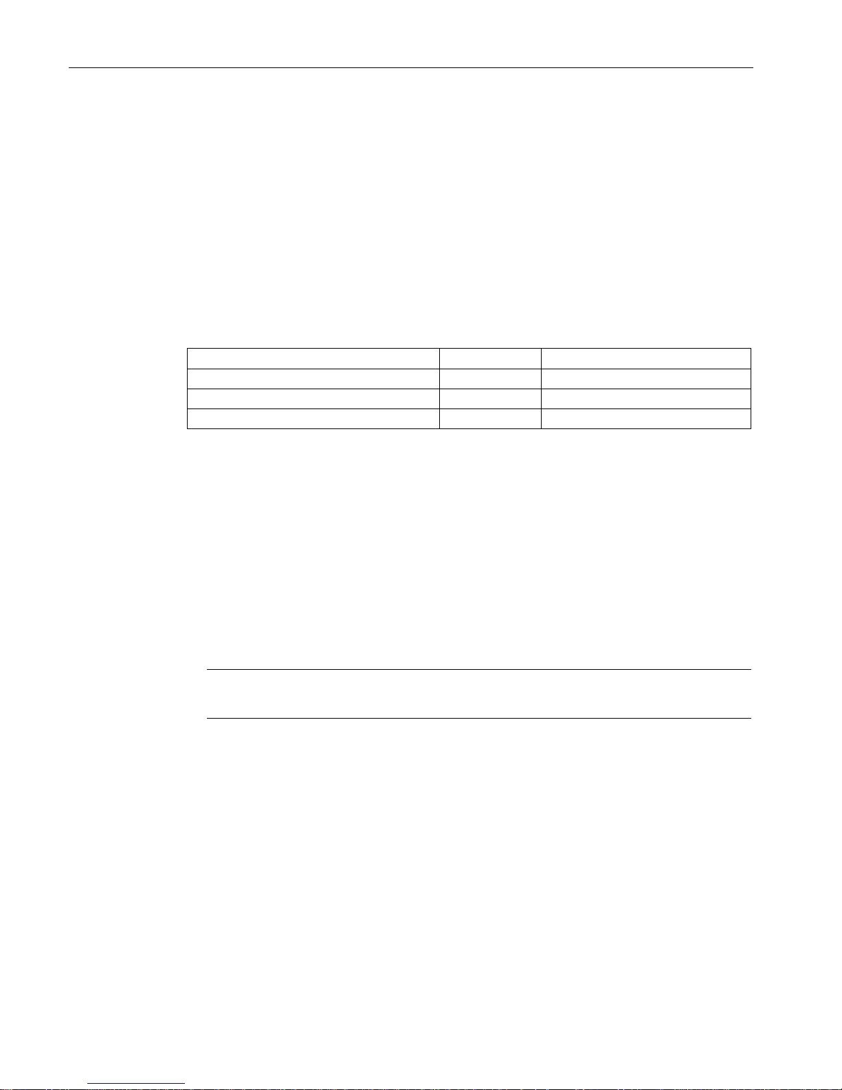
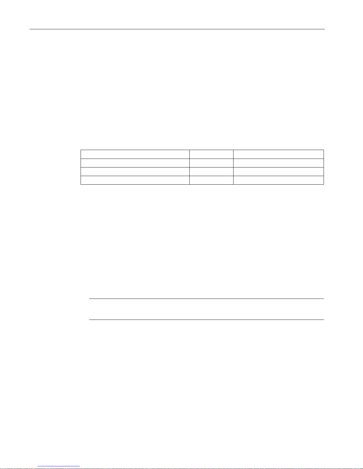
Supported Safety Integrated Basic Functions
Safety function
Abbreviation
Safe Torque Off
STO
Yes
Safe Stop 1
SS1
Yes
Safe Brake Control
SBC
Using Safe Brake Adapter
Control options
● Control Unit and terminal (on the power unit)
● PROFIsafe and terminal (on the power unit)
3.1.1.2
Extended Functions
Requirements
● Option
F01
: Safety license for one axis
Note
The term "axes" should also be interpreted
as "drives".
● For Extended Functions with encoder:
Two SMC30 Sensor Modules (HTL/TTL encoders)
Page 19
General information about SINAMICS Safety Integrated
3.1 Supported functions
Safety Integrated
Function Manual, 07/2016, A5E03264275A
19
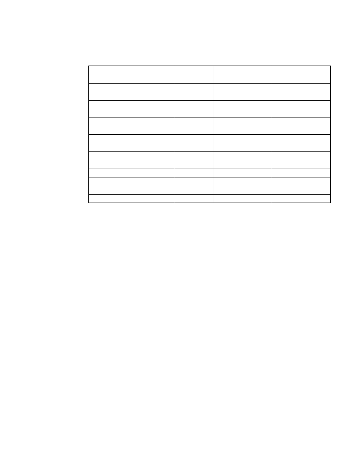
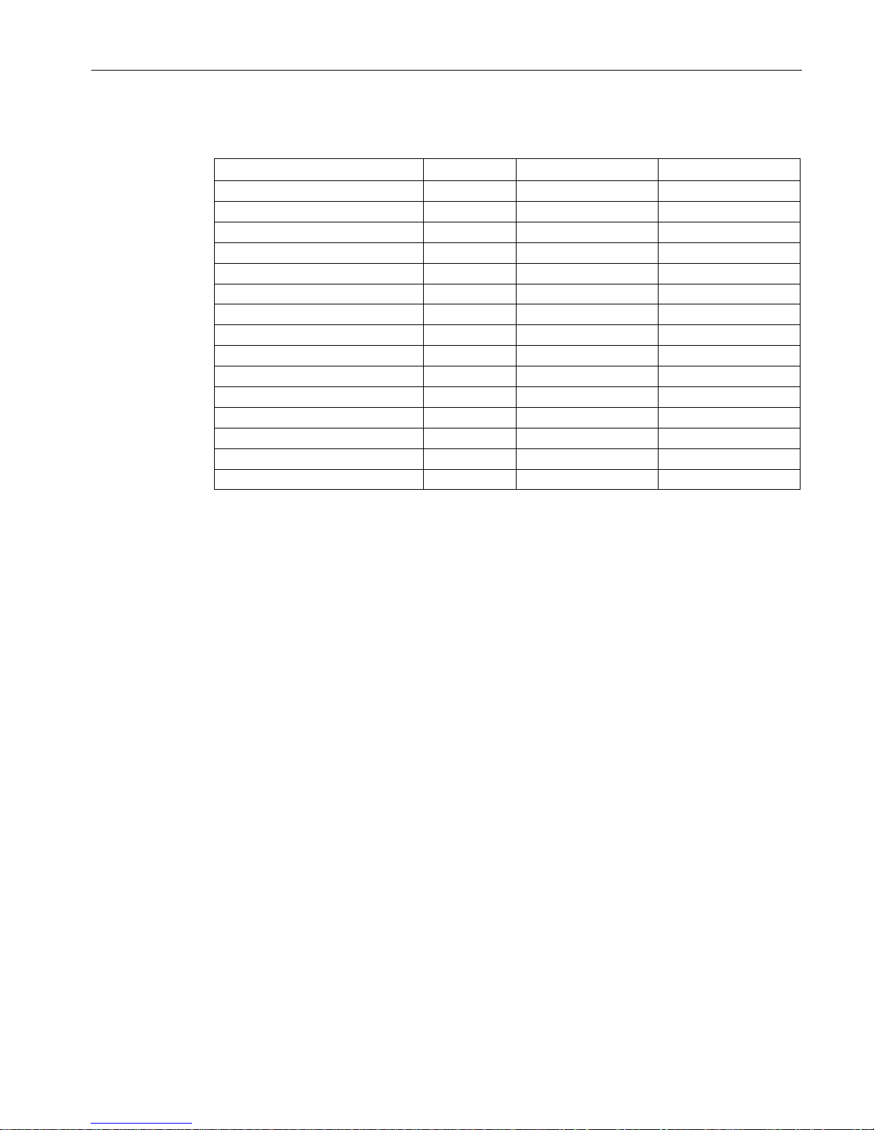
Supported Safety Integrated Extended Functions
Safety function
Abbreviation
With encoder 1)
Without encoder
Safe Torque Off
STO
Yes
Yes 2)
Safe Stop 1
SS1
Yes Yes2)
Safe Brake Control
SBC
Yes
Yes2)
Safe Operating Stop
SOS
Yes
No
Safe Stop 2
SS2
Yes
No
Safely-Limited Speed
SLS
Yes
Yes2)
Safe Speed Monitor
SSM
Yes
Yes2)
Safe Direction
SDI
Yes
Yes2)
Safely-Limited Position
SLP
Yes
No
Safe referencing/homing
SR
Yes
No
Transferring safe position values
SP
Yes
Yes2)
Safe Brake Test
SBT
Yes
No
Safe Acceleration Monitor
SAM
Yes
Yes2)
Safe Brake Ramp
SBR
No
Yes2)
Safe gearbox stage switchover
--
Yes
No
1)
Two SMC30 Sensor Modules (HTL/TTL encoders)
2)
The use of this safety function without an encoder is permitted only for induction motors.
3)
Using Safe Brake Adapter.
Control options
● Terminal Module TM54F
● PROFIsafe
Page 20
General information about SINAMICS Safety Integrated
3.1 Supported functions
Safety Integrated
20 Function Manual, 07/2016, A5E03264275A
3.1.2
SINAMICS G150
3.1.2.1
Basic functions
Requirements
The Safety Integrated Basic Functions are part of the standard scope of the drive and can be
used without an additional license.
Supported Safety Integrated Basic Functions
Safety function
Abbreviation
Safe Torque Off
STO
Yes
Safe Stop 1
SS1
Yes
Safe Brake Control
SBC
Via option K88
Control options
● With option
K82
: Terminal Module for controlling safety functions "STO" and "SS1"
● Control Unit and terminal (on the power unit)
● PROFIsafe and terminal (on the power unit)
3.1.2.2
Extended Functions
Requirements
● Option
K01
: Safety license for one axis
Note
The term "axes" should also be interpreted as "drives".
● For Extended Functions with encoder:
Options
K50 and K52
: Two SMC30 Sensor Modules (HTL/TTL encoders)
Page 21
General information about SINAMICS Safety Integrated
3.1 Supported functions
Safety Integrated
Function Manual, 07/2016, A5E03264275A
21
Supported Safety Integrated Extended Functions
Safety function
Abbreviation
With encoder 1)
Without encoder
Safe Torque Off
STO
Yes
Yes2)
Safe Stop 1
SS1
Yes Yes2)
Safe Brake Control
3)
SBC
Yes
Yes2)
Safe Operating Stop
SOS
Yes
No
Safe Stop 2
SS2
Yes
No
Safely-Limited Speed
SLS
Yes
Yes2)
Safe Speed Monitor
SSM
Yes
Yes2)
Safe Direction
SDI
Yes
Yes2)
Safely-Limited Position
SLP
Yes
No
Safe referencing/homing
SR
Yes
No
Transferring safe position values
SP
Yes
Yes2)
Safe Brake Test
SBT
Yes
No
Safe Acceleration Monitor
SAM
Yes
Yes2)
Safe Brake Ramp
SBR
No
Yes2)
Safe gearbox stage switchover
--
Yes
No
1)
Options
K50 and K52
: Two SMC30 Sensor Modules (HTL/TTL encoders)
2)
The use of this safety function without an encoder is permitted only for induction motors.
3)
Using Safe Brake Adapter (option K88).
Control options
● Option
K87
: Terminal Module TM54F
● PROFIsafe
Page 22
General information about SINAMICS Safety Integrated
3.1 Supported functions
Safety Integrated
22 Function Manual, 07/2016, A5E03264275A
3.1.3
SINAMICS S120 chassis
3.1.3.1
Basic functions
Requirements
The Safety Integrated Basic Functions are part of the standard scope of the drive and can be
used without an additional license.
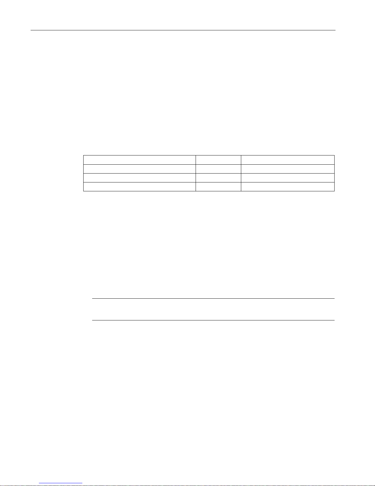
Supported Safety Integrated Basic Functions
Safety function
Abbreviation
Safe Torque Off
STO
Yes
Safe Stop 1
SS1
Yes
Safe Brake Control
SBC
Using Safe Brake Adapter
Control options
● Control Unit and terminal (on the power unit)
● PROFIsafe and terminal (on the power unit)
3.1.3.2
Extended Functions
Requirements
● Option
F01 to F05
: Safety license for one to five axes
Note
The term "axes" should also be interpreted as "drives".
● For Extended Functions with encoder:
– Sin/cos sensor evaluation (SMC20, SME20/25/120/125, SMI20 Sensor Modules) or
– Two SMC30 Sensor Modules (HTL/TTL encoders)
Page 23
General information about SINAMICS Safety Integrated
3.1 Supported functions
Safety Integrated
Function Manual, 07/2016, A5E03264275A
23
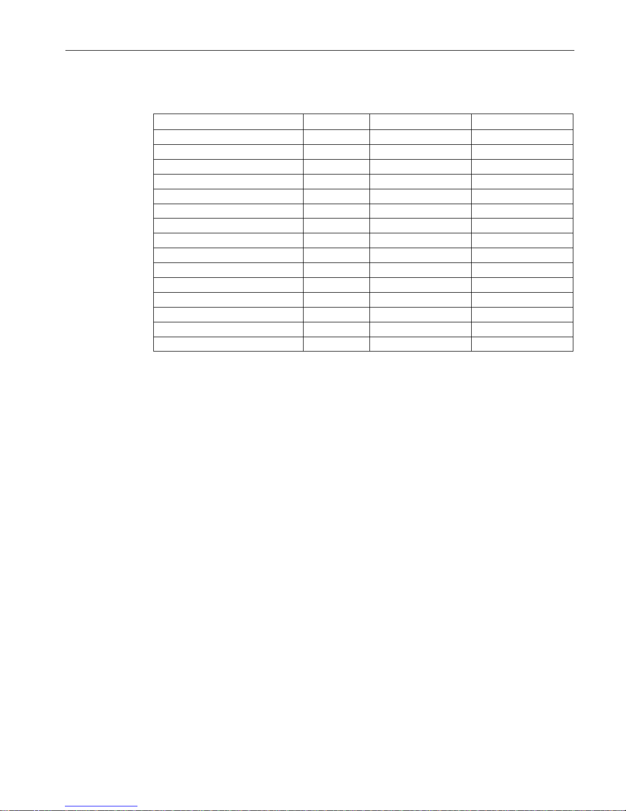
Supported Safety Integrated Extended Functions
Safety function
Abbreviation
With encoder 1)
Without encoder
Safe Torque Off
STO
Yes
Yes2)
Safe Stop 1
SS1
Yes Yes2)
Safe Brake Control
3)
SBC
Yes
Yes2)
Safe Operating Stop
SOS
Yes
No
Safe Stop 2
SS2
Yes
No
Safely-Limited Speed
SLS
Yes
Yes2)
Safe Speed Monitor
SSM
Yes
Yes2)
Safe Direction
SDI
Yes
Yes2)
Safely-Limited Position
SLP
Yes
No
Safe referencing/homing
SR
Yes
No
Transferring safe position values
SP
Yes
Yes2)
Safe Brake Test
SBT
Yes
No
Safe Acceleration Monitor
SAM
Yes
Yes2)
Safe Brake Ramp
SBR
No
Yes2)
Safe gearbox stage switchover
--
Yes
No
1)
Sin/cos sensor evaluation or 2 SMC30 Sensor Modules (HTL/TTL encoders)
2)
The use of this safety function without an encoder is permitted only for induction motors.
3)
Using Safe Brake Adapter.
Control options
● Terminal (TM54F)
● PROFIsafe
Page 24
General information about SINAMICS Safety Integrated
3.1 Supported functions
Safety Integrated
24 Function Manual, 07/2016, A5E03264275A
3.1.4
SINAMICS S120 Cabinet Modules, booksize format
3.1.4.1
Basic functions
Requirements
The Safety Integrated Basic Functions are part of the standard scope of the drive and can be
used without an additional license.
Supported Safety Integrated Basic Functions
Safety function
Abbreviation
Safe Torque Off
STO
Yes
Safe Stop 1
SS1
Yes
Safe Brake Control
SBC
Using Safe Brake Adapter
Control options
● With option
K82
: Terminal Module for controlling safety functions "STO" and "SS1"
● Control Unit and terminal (on the power unit)
● PROFIsafe and terminal (on the power unit)
3.1.4.2
Extended Functions
Requirements
● Option
K01 to K05
: Safety license for one to five axes
Note
The term "axes" should also be interpreted as "drives".
● For Extended Functions with encoder
– Option
K48
: SMC20 Sensor Module (sin/cos encoder) or
– Options
K50 and K52
: Two SMC30 Sensor Modules (HTL/TTL encoders)
Page 25
General information about SINAMICS Safety Integrated
3.1 Supported functions
Safety Integrated
Function Manual, 07/2016, A5E03264275A
25
Supported Safety Integrated Extended Functions
Safety function
Abbreviation
With encoder 1)
Without encoder
Safe Torque Off
STO
Yes
Yes2)
Safe Stop 1
SS1
Yes Yes2)
Safe Brake Control
SBC
Yes
Yes2)
Safe Operating Stop
SOS
Yes
No
Safe Stop 2
SS2
Yes
No
Safely-Limited Speed
SLS
Yes
Yes2)
Safe Speed Monitor
SSM
Yes
Yes2)
Safe Direction
SDI
Yes
Yes2)
Safely-Limited Position
SLP
Yes
No
Safe referencing/homing
SR
Yes
No
Transferring safe position values
SP
Yes
Yes2)
Safe Brake Test
SBT
Yes
No
Safe Acceleration Monitor
SAM
Yes
Yes2)
Safe Brake Ramp
SBR
No
Yes2)
Safe gearbox stage switchover
--
Yes
No
1)
Option
K48
: SMC20 Sensor Module (sin/cos encoder) or
options
K50 and K52
: Two SMC30 Sensor Modules (HTL/TTL encoders)
2)
The use of this safety function without encoder is permitted only for induction motors or synchro-
nous motors of the SIEMOSYN series.
Control options
● Option
K87
: Terminal Module TM54F
● PROFIsafe
Page 26

General information about SINAMICS Safety Integrated
3.1 Supported functions
Safety Integrated
26 Function Manual, 07/2016, A5E03264275A
3.1.5
SINAMICS S120 Cabinet Modules, chassis format
3.1.5.1
Basic functions
Requirements
The Safety Integrated Basic Functions are part of the standard scope of the drive and can be
used without an additional license.
Supported Safety Integrated Basic Functions
Safety function
Abbreviation
Safe Torque Off
STO
Yes
Safe Stop 1
SS1
Yes
Safe Brake Control
SBC
Via option K88
Control options
● With option
K82
: Terminal Module for controlling safety functions "STO" and "SS1"
● Control Unit and terminal (on the power unit)
● PROFIsafe and terminal (on the power unit)
3.1.5.2
Extended Functions
Requirements
● Option
K01 to K05
: Safety license for one to five axes
Note
The term "axes" should also be interpreted as "drives".
● For Extended Functions with encoder:
– Option
K48
: SMC20 Sensor Module (sin/cos encoder) or
– Options
K50 and K52
: Two SMC30 Sensor Modules (HTL/TTL encoders)
Page 27
General information about SINAMICS Safety Integrated
3.1 Supported functions
Safety Integrated
Function Manual, 07/2016, A5E03264275A
27
Supported Safety Integrated Extended Functions
Safety function
Abbreviation
With encoder 1)
Without encoder
Safe Torque Off
STO
Yes
Yes2)
Safe Stop 1
SS1
Yes Yes2)
Safe Brake Control
3)
SBC
Yes
Yes2)
Safe Operating Stop
SOS
Yes
No
Safe Stop 2
SS2
Yes
No
Safely-Limited Speed
SLS
Yes
Yes2)
Safe Speed Monitor
SSM
Yes
Yes2)
Safe Direction
SDI
Yes
Yes2)
Safely-Limited Position
SLP
Yes
No
Safe referencing/homing
SR
Yes
No
Transferring safe position values
SP
Yes
Yes2)
Safe Brake Test
SBT
Yes
No
Safe Acceleration Monitor
SAM
Yes
Yes2)
Safe Brake Ramp
SBR
No
Yes2)
Safe gearbox stage switchover
--
Yes
No
1)
Option
K48
: SMC20 Sensor Module (sin/cos encoder) or
options
K50 and K52
: Two SMC30 Sensor Modules (HTL/TTL encoders)
2)
The use of this safety function without an encoder is permitted only for induction motors.
3)
Using Safe Brake Adapter (option K88).
Control options
● Option
K87
: TM54F Terminal Module
● PROFIsafe
Page 28
General information about SINAMICS Safety Integrated
3.1 Supported functions
Safety Integrated
28 Function Manual, 07/2016, A5E03264275A
3.1.6
SINAMICS S150
3.1.6.1
Basic functions
Requirements
The Safety Integrated Basic Functions are part of the standard scope of the drive and can be
used without an additional license.
Supported Safety Integrated Basic Functions
Safety function
Abbreviation
Safe Torque Off
STO
Yes
Safe Stop 1
SS1
Yes
Safe Brake Control
SBC
Via option K88
Control options
● With option
K82
: Terminal Module for controlling safety functions "STO" and "SS1"
● Control Unit and terminal (on the power unit)
● PROFIsafe and terminal (on the power unit)
3.1.6.2
Extended Functions
Requirements
● Option
K01
: Safety license for one axis
Note
The term "axes" sh
ould also be interpreted as "drives".
● For Extended Functions with encoder:
– Option
K48
: SMC20 Sensor Module (sin/cos encoder) or
– Options
K50 and K52
: Two SMC30 Sensor Modules (HTL/TTL encoders)
Page 29
General information about SINAMICS Safety Integrated
3.2 Drive monitoring with or without encoder
Safety Integrated
Function Manual, 07/2016, A5E03264275A
29
Supported Safety Integrated Extended Functions
Safety function
Abbreviation
With encoder 1)
Without encoder
Safe Torque Off
STO
Yes
Yes2)
Safe Stop 1
SS1
Yes Yes2)
Safe Brake Control
3)
SBC
Yes
Yes2)
Safe Operating Stop
SOS
Yes
No
Safe Stop 2
SS2
Yes
No
Safely-Limited Speed
SLS
Yes
Yes2)
Safe Speed Monitor
SSM
Yes
Yes2)
Safe Direction
SDI
Yes
Yes2)
Safely-Limited Position
SLP
Yes
No
Safe referencing/homing
SR
Yes
No
Transferring safe position values
SP
Yes
Yes2)
Safe Brake Test
SBT
Yes
No
Safe Acceleration Monitor
SAM
Yes
Yes2)
Safe Brake Ramp
SBR
No
Yes2)
Safe gearbox stage switchover
--
Yes
No
1)
Option
K48
: SMC20 Sensor Module (sin/cos encoder) or
options
K50 and K52
: Two SMC30 Sensor Modules (HTL/TTL encoders)
2)
The use of this safety function without an encoder is permitted only for induction motors.
3)
Using Safe Brake Adapter (option K88).
Control options
● Option
K87
: TM54F Terminal Module
● PROFIsafe
3.2
Drive monitoring with or without encoder
If motors without a (safety-capable) encoder are being used, not all Safety Integrated
functions are available.
Note
Definition: "Without encoder"
When "without encoder" is used in this manual, then this always means that either no
encoder or no safety
-capable encoder is being used.
Page 30

General information about SINAMICS Safety Integrated
3.2 Drive monitoring with or without encoder
Safety Integrated
30 Function Manual, 07/2016, A5E03264275A
In operation without encoder, the actual speed values are calculated from the measured
electrical actual values. Therefore, speed monitoring is also possible during operation
without encoder.
Table 3- 1 Overview of Safety Integrated functions
Functions
Abbr.
With
encoder
Without
encoder
Brief description
Basic Functions
Safe Torque Off
STO
Yes
Yes
Safe Torque Off
Safe Stop 1 SS1 Yes Yes Safe stop according to stop category 1
Safe Brake Control
SBC
Yes
Yes
Safe Brake Control
Extended Func-
tions
Safe Torque Off
STO
Yes
Yes1)
Safe Torque Off
Safe Stop 1
SS1
Yes
Yes1)
Safe stop according to stop category 1
Safe Brake Control
SBC
Yes
Yes1)
Safe Brake Control
Safe Operating Stop
SOS
Yes
No
Safe monitoring of the standstill position
Safe Stop 2
SS2
Yes
No
Safe stop according to stop category 2
Safely-Limited Speed
SLS
Yes
Yes1)
Safe monitoring of the maximum speed
Safe Speed Monitor
SSM
Yes
Yes1)
Safe monitoring of the minimum speed
Safe Direction
SDI
Yes
Yes1)
Safe monitoring of the direction of motion
Safely-Limited Position
SLP
Yes
No
Safely-limited position
Safe referencing/homing
SR
Yes
No
Safe referencing/homing
Transferring safe position
values
SP Yes Yes1) Transferring safe position values
Safe Brake Test SBT Yes No Safe test of the required holding torque of a
brake
Safe Acceleration Monitor
SAM
Yes
Yes1)
Safe monitoring of drive acceleration
Safe Brake Ramp
SBR
No
Yes1)
Safe braking ramp
Safe gearbox stage switch-
over
– Yes No –
1)
The use of this safety function without encoder is permitted only for induction motors or synchronous motors of the
SIEMOSYN series.
The configuration of the Safety Integrated functions and the selection of monitoring with or
without encoder is realized in the Safety screens of the STARTER or SCOUT tools.
Page 31

Safety Integrated
Function Manual, 07/2016, A5E03264275A
31
4
Safety Integrated Basic Functions and Safety Integrated Extended Functions are described
in detail in the "SINAMICS S120 Safety Integrated Function Manual".
The "SINAMICS S120 Safety Integrated Function Manual" is available on the Internet at the
following address (https://support.industry.siemens.com/cs/ww/en/ps/13231/man).
4.1
Preconditions for Safety Integrated Basic Functions
The following prerequisites apply for operation of the Safety Integrated Basic Functions:
● For G150, S120 Cabinet Modules and S150:
Option K82 (Terminal Module for activation of the safety functions "Safe Torque Off" and
"Safe Stop 1"), for activation signals of 230 V and/or cable lengths of more than 30 m
● An activated current controller in the drive
● For the safe brake control:
– For G150, S120 Cabinet Modules and S150:
Option K88 (Safe Brake Adapter 230 VAC)
– For the G130 and S120 Chassis units:
Option SBA (Safe Brake Adapter)
Page 32

Description of Safety Integrated functions
4.2 Preconditions for Safety Integrated Extended Functions
Safety Integrated
32 Function Manual, 07/2016, A5E03264275A
4.2
Preconditions for Safety Integrated Extended Functions
● For operation of the Safety Integrated Extended Functions,
one
license is required for
each
axis.
● Control possible via
– PROFIsafe
– TM54F
– Active functions without control (SLS, SDI)
● An activated current controller in the drive
● Overview of hardware components that support the Extended Functions:
– Motor Modules booksize with an article number ending: -xxx3 or higher
– Motor Modules chassis with an article number ending: -xxx3 or higher
– Motor Modules cabinet with an article number ending: -xxx2 or higher
– Control Unit Adapter CUA31 as of article number: 6SL3040-0PA00-0AA1
– Control Unit Adapter CUA32 as of article number: 6SL3040-0PA01-0AA0
– For the Extended Functions with encoder:
Motors with sin/cos encoder and encoder evaluation with DRIVE-CLiQ interface or via
Sensor Module SMC20, SME20/25/120/125
Motors with two independent HTL/TTL encoders or a special double HTL/TTL encoder
The list of approved encoders can be found on the Internet at:
https://support.industry.siemens.com
Enter the number
33512621
there as search term or contact your local Siemens office.
Page 33
Safety Integrated
Function Manual, 07/2016, A5E03264275A
33
5
5.1
Control possibilities
The following options for controlling Safety Integrated functions are available:
Table 5- 1 Controlling the Safety Integrated functions
Terminals (on the
Control Unit and
Motor/Power Module)
PROFIsafe
based on
PROFIBUS or
PROFINET
TM545F
Control without
selection
Basic Functions Yes Yes No No
Extended Functions
No
Yes
Yes
SLS, SDI
Note
PROFIsafe or TM54F
Using a Control Unit, control is possible either via PR
OFIsafe or TM54F. Mixed operation is
not permissible.
The safety-related input and output terminals (F-DI and F-DO) act as an interface between
the SINAMICS Safety Integrated functionality and the process.
A dual-channel signal applied to an F-DI (Fail-safe Digital Input, safety-oriented digital input
= safe input terminal pair) controls the active monitoring of the activation/deactivation of
safety functions.
An F-DO (Fail-safe Digital Output, safety-oriented digital output = safe output terminal pair)
delivers a dual channel signal representing feedback from the safety functions.
Dual-channel processing of I/O signals
A dual-channel structure is realized for data input/output and for processing fail-safe I/O
signals. All requests and feedback signals for fail-safe functions should be entered or picked
off using both channels.
Page 34

Controlling the safety functions
5.2 Control of "STO" and "SS1" via terminal module for option K82
Safety Integrated
34 Function Manual, 07/2016, A5E03264275A
5.2
Control of "STO" and "SS1" via terminal module for option K82
5.2.1
Terminal module for control of "STO" and "SS1" for SINAMICS G150
Description
Option K82 (Terminal Module for activating "Safe Torque Off" and "Safe Stop 1") is used for
isolated activation of the Safety Integrated Basic Functions over a wide voltage range.
Note
Refer to the circuit diagrams enclosed for the in
terconnections of your device.
Note
The Safety functions must be activated prior to use via parameter assignment. An
acceptance test must be performed and an acceptance log must be created.
Option K82 is used to activate the following Safety Integrated Basic Functions (terms and
definitions according to IEC 61800-5-2):
● Safe Torque Off (STO)
● Safe Stop 1 (SS1) (time-controlled)
Note
The integrated safety functions, starting from the Safety Integrated (SI) input terminals of the
SINAMICS components
(Control Unit, Power Module), satisfy the requirements of
EN
61800-5-2, EN 60204-1 and DIN EN ISO 13849-1 category 3 (formerly EN 954-1), as
well as the requirements for Performance Level (PL) d and IEC 61508 SIL2.
In combination with the option K82, the r
equirements specified in EN 61800-5-2, EN
60204
-1, as well as in DIN EN ISO 13849-1 category 3 (formerly EN954-1) are satisfied for
Performance Level (PL) d and IEC 61508 SIL2.
In addition, most of the SINAMICS safety functions have been certified by independent
institutes. A list of currently certified components is available on request from your local
Siemens office.
Page 35
Controlling the safety functions
5.2 Control of "STO" and "SS1" via terminal module for option K82
Safety Integrated
Function Manual, 07/2016, A5E03264275A
35
Recommended application
This option is used when the following requirements apply:
● Activation will be executed isolated in a voltage range of 24 VDC - 230 VAC.
● Using non-shielded control lines which are longer than 30 m.
● The devices are deployed in plants dispersed over a wide area (no ideal equipotential
bonding).
Principle of operation
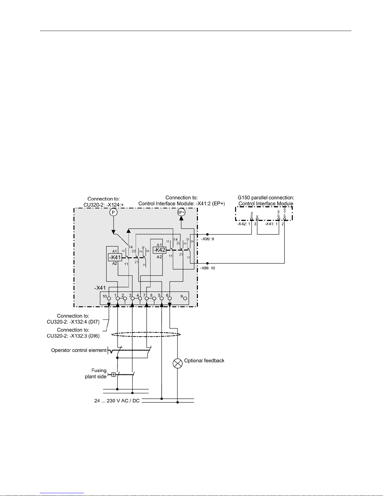
Two independent channels of the integrated safety function are controlled via relays (K41,
K42).
Relay K41 controls the signal at the Control Unit that is necessary for the safety function and
relay K42, the corresponding signal at the Power Module.
The selection and deselection must be simultaneous. The time delay that is unavoidable due
to mechanical switching processes, for example, can be adapted via parameters. p9650
specifies the tolerance time within which the selection/deselection of the two monitoring
channels must occur in order to be considered as "simultaneous".
The circuit is structured so that it is protected against wire break, i.e. if the relay's control
voltage fails then the safety function is active.
A checkback signal can be derived for information, diagnostics or troubleshooting from the
normally-closed contacts of the relay switched in series. Wiring of the checkback signal can
be performed optionally and is not part of the safety concept.
Note
The feedback signal is not necessary to comply with standard DIN EN ISO 13849-1 (formerly
EN
954-1) Cat. 3 PL d and DIN EN 61508 SIL2.
The selection of the safety function must be performed in two channels. A switch according
to ISO 13850/ EN 418, positive opening according to EC 60947-5-1, or a certified safety
controller must be used as actuating element.
WARNING
Danger to life as a result of failure of the safety functions through unsuitable selection of the
actuating element
An unsuitable actuating element may cause the safety function to fail which can result in
death or serious injury.
• Select the correct actuating element for the purpose of compliance of the overall system
with the required standard (DIN EN ISO 13849-1 (formerly EN954-1) Cat. 3 PL d or DIN
EN 61508 SIL2).
Page 36
Controlling the safety functions
5.2 Control of "STO" and "SS1" via terminal module for option K82
Safety Integrated
36 Function Manual, 07/2016, A5E03264275A
Forced checking procedure
The maximum value for the forced checking procedure interval when using option K82 is
6 months (4380 h).
Customer interface -X41
Table 5- 2 Terminal strip -X41
Terminal
Meaning
Technical data
-X41:1
Control of -K41:A1
Connection for actuating element at channel 1 "+"
-X41:2 Connected to -X41:1
-X41:3 Control of -K41:A2, -K42:A2 , N conductor or ground Connection of reference potential for actuating ele-
ments at channel 1 and channel 2
-X41:4 Connected to -X41:3
-X41:5 Feedback signal, status -K41, -K42 Connection of supply voltage for optional feedback
signal
-X41:6
Feedback signal, status -K41, -K42
Connection of optional checkback signal
-X41:7
Control of -K42:A1
Connection for actuating element at channel 2 "+"
-X41:8
Connected to -X41:7
-X41:9
Not assigned
-X41:10 Output -K41: Permanently wired with CU320-2:
-X132:4 (DI 7)
Control circuit:
Rated voltage: 24 VDC to 230 VAC (0.85 ... 1.1 x Us)
Max. line length (applies to the sum of the outgoing and return lines):
● AC (line capacity: 300 pF/m):
– 24 V: 5000 m
– 110 V: 800 m
– 230 V: 200 m
The values apply for 50 Hz, at 60 Hz the line lengths must be reduced by 20%.
WARNING
Danger to life as a result of exceeding the permissible cable lengths and/or the
permissible cable capacitances
When the permissible cable lengths and/or the permissible cable capacitances are
exceeded, the relay can remain energized as a result of the coupling capacitances of
the cable and the associated residual current, in spite of the fact that the actuating
elements are open. Death and serious injury can result in the event of an error.
• Do not exceed the maximum permissible cable lengths and cable capacitances.
● DC (min. cross-section 0.75 mm²): 1500 m
Page 37
Controlling the safety functions
5.2 Control of "STO" and "SS1" via terminal module for option K82
Safety Integrated
Function Manual, 07/2016, A5E03264275A
37
Max. connectable cross-section: 2.5 mm²
Fuse: Max. 4 A
Load side:
Switching voltage: Max. 250 VDC/AC
Rated operating currents:
● AC-15 (according to IEC 60947-5-1): 24 ... 230 V = 3 A
● DC-13 (according to IEC 60947-5-1):
– 24 V = 1 A
– 110 V = 0.2 A
– 230 V = 0.1 A
Min. contact load: 5 VDC, 1 mA at 1 ppm error
Fuse: Max. 4 A (fuse weld-free, duty category gL/gG with Ik ≥ 1 kA)
Figure 5-1 Circuit Terminal Module for option K82
A switch according to ISO 13850/ EN 418, positive opening according to EC 60947-5-1, or a
certified safety controller must be used as actuating element.
Page 38

Controlling the safety functions
5.2 Control of "STO" and "SS1" via terminal module for option K82
Safety Integrated
38 Function Manual, 07/2016, A5E03264275A
Note
Terminal
-X41:10 is permanently connected to the digital input DI 7 of the Control Unit.
Note
For the following cabinet units (parallel switchgear), digital input DI 6 of the Control Unit is
also assigned:
•
For 380 to 480 V 3 AC:
6SL3710-2GE41-1AAx, 6SL3710-2GE41-4AAx, 6SL3710-2GE41-6AAx
•
For 500 to 600 V 3 AC:
6SL3710-2GF38-6AAx, 6SL3710-2GF41-1AAx, 6SL3710-2GF41-4AAx
•
For 660 to 690 V 3 AC:
6SL3710-2GH41-1AAx, 6SL3710-2GH41-4AAx, 6SL3710-2GH41-5AAx
Interconnection in groups
When using a single actuating element for multiple cabinet units, the following terminals
have to be used on terminal strip -X41:
● -X41:2: Interconnection to the next cabinet unit, terminal -X41:1
● -X41:4: Interconnection to the next cabinet unit, terminal -X41:3
● -X41:6: Interconnection to the next cabinet unit, terminal -X41:5
● -X41:8: Interconnection to the next cabinet unit, terminal -X41:7
● -X41:9: Interconnection to the next cabinet unit, terminal -X41:6
● Connection of the optional checkback signal to terminal -X41:9
Wiring
The control cables should be permanently routed (e.g. cable duct, retained using cable ties).
Signal cables and encoder cables should be installed separated from one another.
The shields of the control cables should be grounded through the largest possible surface
area immediately after they enter the control cabinet.
Outside the control cabinet, the cables must be routed in such a way that they are safe to
walk on (e.g. as specified in IEC 60204-1).
Page 39

Controlling the safety functions
5.2 Control of "STO" and "SS1" via terminal module for option K82
Safety Integrated
Function Manual, 07/2016, A5E03264275A
39
5.2.2
Terminal module for control of "STO" and "SS1" for SINAMICS S120 Cabinet
Modules
5.2.2.1
General information
Availability of the option
This option is available for the following S120 Cabinet Modules:
● Motor Module in chassis format
● Booksize Cabinet Kit
Description
Option K82 (Terminal Module for activating "Safe Torque Off" and "Safe Stop 1") is used for
isolated activation of the Safety Integrated Basic Functions over a wide voltage range.
Note
Refer to the circuit diagrams enclosed for the interconnections of your device.
Note
The Safety functions must be activated prior to use via parameter assignment
. An
acceptance test must be performed and an acceptance log must be created.
Option K82 is used to activate the following Safety Integrated Basic Functions (terms and
definitions according to IEC 61800-5-2):
● Safe Torque Off (STO)
● Safe Stop 1 (SS1) (time-controlled)
Note
The integrated safety functions, starting from the Safety Integrated (SI) input terminals of the
SINAMICS components (Control Unit, Motor Module), satisfy the requirements of
EN
61800-5-2, EN 60204-1 and DIN EN ISO 13849-1 category 3 (formerly EN 954-1), as
well as the requirements for Performance Level (PL) d and IEC 61508 SIL2.
In combination with the option K82, the requirements specified in EN
61800-5-2, EN
60204
-1, as well as in DIN EN ISO 13849-1 category 3 (formerly EN954-1) are satisfied for
Performance Level (PL) d and IEC 61508 SIL2.
In addition, most of the SINAMICS safety functions have been certified by independent
institutes. A list of currently certified components is available on request from your local
Siemens office.
Page 40
Controlling the safety functions
5.2 Control of "STO" and "SS1" via terminal module for option K82
Safety Integrated
40 Function Manual, 07/2016, A5E03264275A
Recommended application
This option is used when the following requirements apply:
● Activation will be executed isolated in a voltage range of 24 VDC - 230 VAC.
● Using non-shielded control lines which are longer than 30 m.
● The devices are deployed in plants dispersed over a wide area (no ideal equipotential
bonding).
Principle of operation
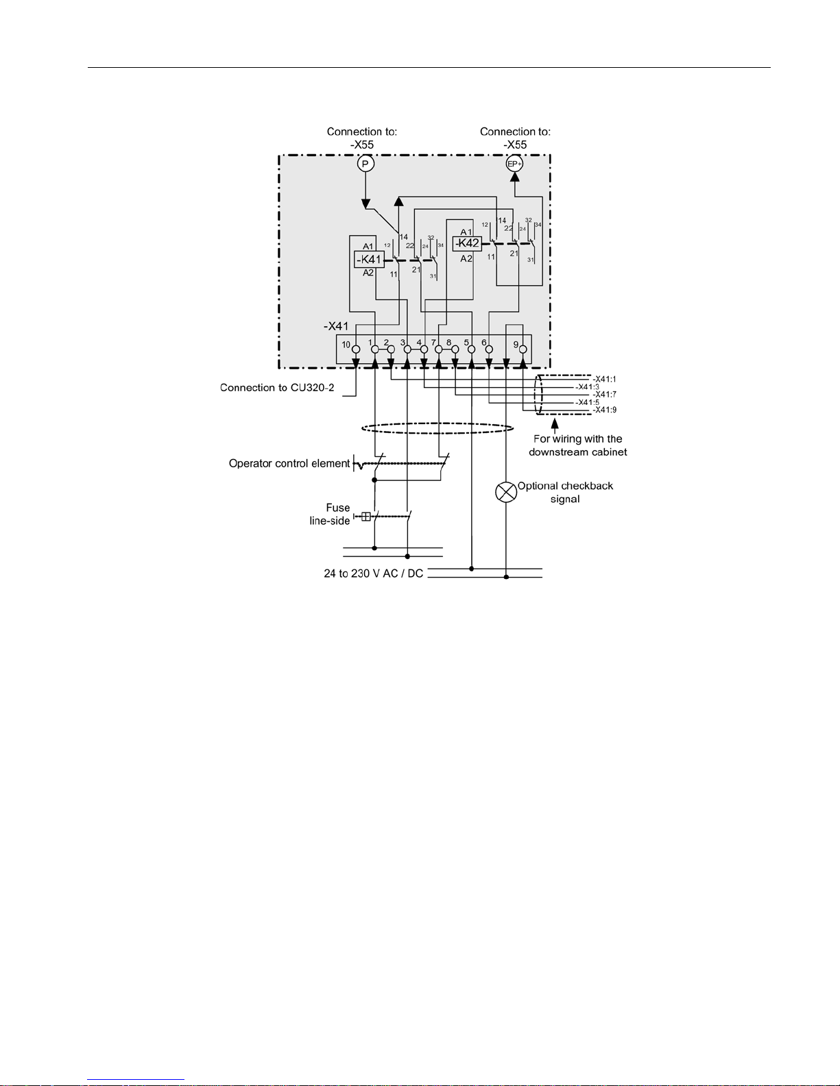
Two independent channels of the integrated safety function are controlled via relays (K41,
K42).
Relay K41 controls the signal at the Control Unit that is necessary for the safety function and
relay K42, the corresponding signal at the Motor Module.
The selection and deselection must be simultaneous. The time delay that is unavoidable due
to mechanical switching processes, for example, can be adapted via parameters. p9650
specifies the tolerance time within which the selection/deselection of the two monitoring
channels must occur in order to be considered as "simultaneous".
The circuit is structured so that it is protected against wire break, i.e. if the relay's control
voltage fails then the safety function is active.
A checkback signal can be derived for information, diagnostics or troubleshooting from the
normally-closed contacts of the relay switched in series.
Wiring of the checkback signal can be performed optionally and is not part of the safety
concept.
Note
The checkback signal is not necessary for compliance with the standard DIN EN ISO 13849
-
1 (formerly EN954
-1) cat. 3 PL d and DIN EN 61508 SIL2.
The selection of the safety function must be performed in two channels. A switch according
to ISO 13850/ EN 418, positive opening according to EC 60947-5-1, or a certified safety
controller must be used as actuating element.
WARNING
Danger to life as a result of failure of the safety functions through unsuitable selection of the
actuating element
An unsuitable actuating element may cause the safety function to fail which can result in
death or serious injury.
• Select the correct actuating element for the purpose of compliance of the overall system
with the required standard (DIN EN ISO 13849-1 (formerly EN954-1) Cat. 3 PL d or DIN
EN 61508 SIL2).
Page 41

Controlling the safety functions
5.2 Control of "STO" and "SS1" via terminal module for option K82
Safety Integrated
Function Manual, 07/2016, A5E03264275A
41
Forced checking procedure
The maximum value for the forced checking procedure interval when using option K82 is
6 months (4380 h).
Customer interface -X41
Table 5- 3 Terminal strip -X41
Terminal
Meaning
Technical data
-X41:1
Control of -K41:A1
Connection for actuating element at channel 1 "+"
-X41:2 Connected to -X41:1 Connection for actuating element at channel 1 "+", for inter-
connecting Motor Modules in groups
-X41:3 Control of -K41:A2, -K42:A2 , N conductor or
ground
Connection of reference potential for actuating elements at
channel 1 and channel 2
-X41:4 Connected to -X41:3 Connection of reference potential for actuating elements at
channel 1 and channel 2, for interconnecting Motor Modules
in groups
-X41:5
Feedback signal, status -K41, -K42
Connection of supply voltage for optional feedback signal
-X41:6 Feedback signal, status -K41, -K42 Connection for optional checkback signal, for interconnect-
ing Motor Modules in groups
-X41:7
Control of -K42:A1
Connection for actuating element at channel 2 "+"
-X41:8 Connected to -X41:7 Connection for actuating element at channel 2 "+", for inter-
connecting Motor Modules in groups
-X41:9 Connection of optional checkback For the option of connecting other checkback signals in
series when Motor Modules are grouped
-X41:10 Output -K41: Permanently wired with
CU320-2: -X132:4 (DI 7)
Output -K41: For connecting to a digital input according to
the Safety settings on the CU320-2 (already wired in option
K90)
Page 42
Controlling the safety functions
5.2 Control of "STO" and "SS1" via terminal module for option K82
Safety Integrated
42 Function Manual, 07/2016, A5E03264275A
Control circuit:
Rated voltage: 24 VDC to 230 VAC (0.85 ... 1.1 x Us)
Max. line length (applies to the sum of the outgoing and return lines):
● AC (line capacity: 300 pF/m):
– 24 V: 5000 m
– 110 V: 800 m
– 230 V: 200 m
The values apply for 50 Hz, at 60 Hz the line lengths must be reduced by 20%.
WARNING
Danger to life as a result of exceeding the permissible cable lengths and/or the
permissible cable capacitances
When the permissible cable lengths and/or the permissible cable capacitances are
exceeded, the relay can remain energized as a result of the coupling capacitances of
the cable and the associated residual current, in spite of the fact that the actuating
elements are open. Death and serious injury can result in the event of an error.
• Do not exceed the maximum permissible cable lengths and cable capacitances.
● DC (min. cross-section 0.75 mm2): 1500 m
Max. connectable cross-section: 2.5 mm²
Fuse: Max. 4 A
Load side:
Switching voltage: Max. 250 VDC/AC
Rated operating currents:
● AC-15 (according to IEC 60947-5-1): 24 ... 230 V = 3 A
● DC-13 (according to IEC 60947-5-1):
– 24 V = 1 A
– 110 V = 0.2 A
– 230 V = 0.1 A
Min. contact load: 5 VDC, 1 mA at 1 ppm error
Fuse: Max. 4 A (fuse weld-free, duty category gL/gG with Ik ≥ 1 kA)
Page 43
Controlling the safety functions
5.2 Control of "STO" and "SS1" via terminal module for option K82
Safety Integrated
Function Manual, 07/2016, A5E03264275A
43
Figure 5-2 Circuit Terminal Module for option K82
A switch according to ISO 13850/ EN 418, positive opening according to EC 60947-5-1, or a
certified safety controller must be used as actuating element.
5.2.2.2
Use of the K82 option with Control Unit CU320-2
In conjunction with option K90 or K95 (CU320-2 DP or CU320-2 PN), terminal -X41:10 is
already connected inside the cabinet with digital input DI 7 of the CU320-2.
In the Double Motor Module, digital input DI 6 is also wired on the CU320-2.
These interconnections have to be taken into account when Safety function parameters are
assigned.
Page 44

Controlling the safety functions
5.2 Control of "STO" and "SS1" via terminal module for option K82
Safety Integrated
44 Function Manual, 07/2016, A5E03264275A
5.2.2.3
Use of the K82 option with Control Unit CU320-2
If option K90 or K95 is not available, -X41:10 should be connected to the particular Control
Unit associated with the Motor Module. Digital inputs DI 0 to DI 7, DI 16, DI 17, DI 20, DI 21
are available for this purpose.
These interconnections have to be taken into account when Safety function parameters are
assigned.
If the cable is routed to the Control Unit outside the cabinet, then the cable may not be
longer than 30 m. For longer cable lengths, suitable protective circuitry must be provided for
overvoltage protection (Weidmüller, type: MCZ OVP TAZ, order no.: 8449160000).
Note
Terminal
-X41:10 can only be connected with digital inputs DI 0 to DI 7, DI 16, DI 17, DI 20,
DI
21 of the Control Unit, other digital inputs cannot be interconnected.
5.2.2.4
Wiring
The control cables should be permanently routed (e.g. cable duct, retained using cable ties).
Signal cables and encoder cables should be installed separated from one another.
The shields of the control cables should be grounded through the largest possible surface
area immediately after they enter the control cabinet.
Outside the control cabinet, the cables must be routed in such a way that they are safe to
walk on (e.g. as specified in IEC 60204-1).
5.2.3
Terminal module for control of "STO" and "SS1" for SINAMICS S150
Description
Option K82 (Terminal Module for activating "Safe Torque Off" and "Safe Stop 1") is used for
isolated activation of the Safety Integrated Basic Functions over a wide voltage range.
Note
Refer to the circuit diagrams enclosed fo
r the interconnections of your device.
Note
The Safety functions must be activated prior to use via parameter assignment. An
acceptance test must be performed and an acceptance log must be created.
Page 45

Controlling the safety functions
5.2 Control of "STO" and "SS1" via terminal module for option K82
Safety Integrated
Function Manual, 07/2016, A5E03264275A
45
Option K82 is used to activate the following Safety Integrated Basic Functions (terms and
definitions according to IEC 61800-5-2):
● Safe Torque Off (STO)
● Safe Stop 1 (SS1) (time-controlled)
Note
The integrated safety functions, starting from the Safety Integrated (SI) input terminals of the
SINAMICS com
ponents (Control Unit, Motor Module), satisfy the requirements of
EN
61800-5-2, EN 60204-1 and DIN EN ISO 13849-1 category 3 (formerly EN 954-1), as
well as the requirements for Performance Level (PL) d and IEC 61508 SIL2.
In combination with the option K8
2, the requirements specified in EN 61800-5-2, EN
60204
-1, as well as in DIN EN ISO 13849-1 category 3 (formerly EN954-1) are satisfied for
Performance Level (PL) d and IEC 61508 SIL2.
In addition, most of the SINAMICS safety functions have been certified by independent
institutes. A list of currently certified components is available on request from your local
Siemens office.
Recommended application
This option is used when the following requirements apply:
● Activation will be executed isolated in a voltage range of 24 VDC - 230 VAC.
● Using non-shielded control lines which are longer than 30 m.
● The devices are deployed in plants dispersed over a wide area (no ideal equipotential
bonding).
Principle of operation
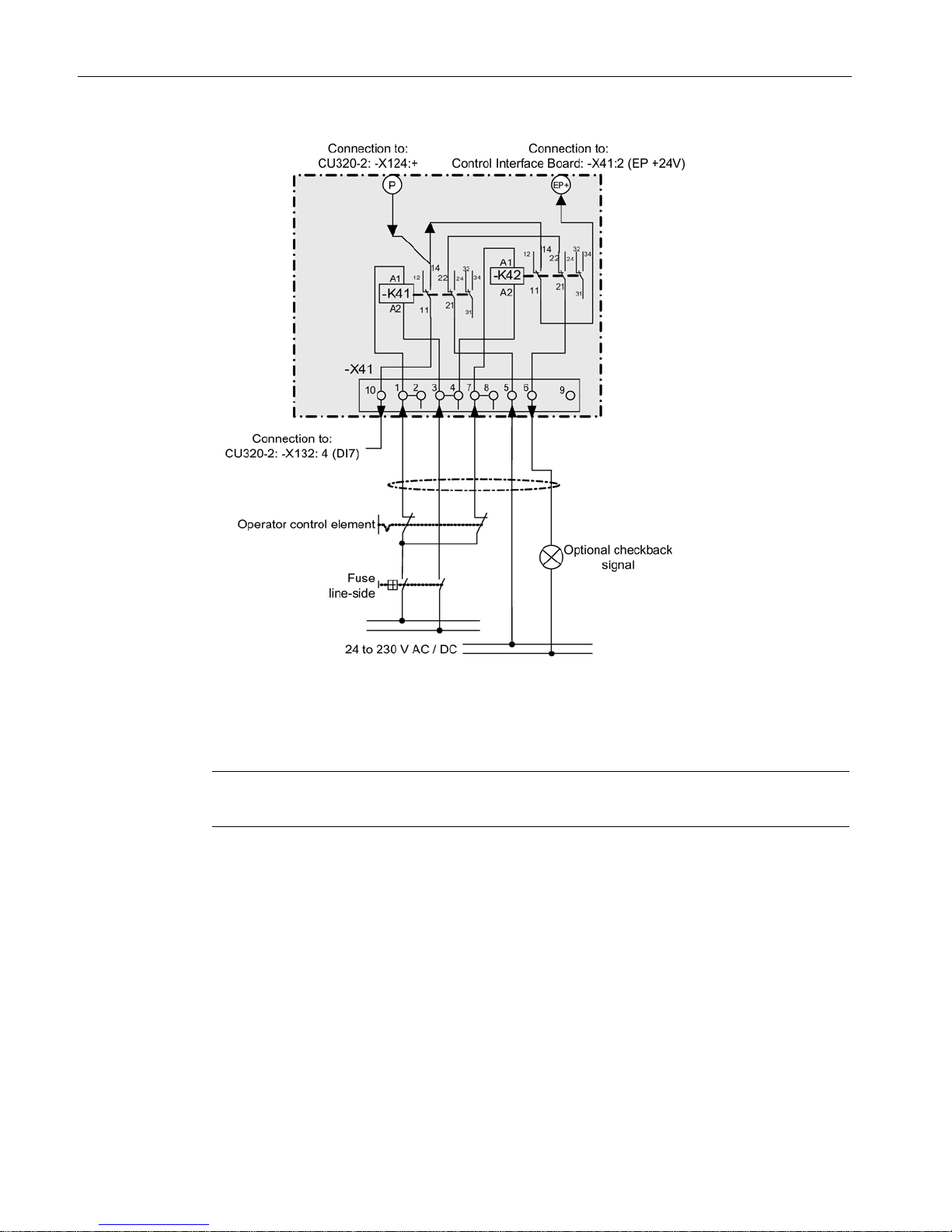
Two independent channels of the integrated safety function are controlled via relays (K41,
K42).
Relay K41 controls the signal at the Control Unit that is necessary for the safety function and
relay K42, the corresponding signal at the Motor Module.
The selection and deselection must be simultaneous. The time delay that is unavoidable due
to mechanical switching processes, for example, can be adapted via parameters. p9650
specifies the tolerance time within which the selection/deselection of the two monitoring
channels must occur in order to be considered as "simultaneous".
The circuit is structured so that it is protected against wire break, i.e. if the relay's control
voltage fails then the safety function is active.
A checkback signal can be derived for information, diagnostics or troubleshooting from the
normally-closed contacts of the relay switched in series. Wiring of the checkback signal can
be performed optionally and is not part of the safety concept.
Page 46
Controlling the safety functions
5.2 Control of "STO" and "SS1" via terminal module for option K82
Safety Integrated
46 Function Manual, 07/2016, A5E03264275A
Note
The checkback signal is not necessary for compliance with the standard DIN EN ISO 138
49-
1 (formerly EN954
-1) cat. 3 PL d and DIN EN 61508 SIL2.
The selection of the safety function must be performed in two channels. A switch according
to ISO 13850/ EN 418, positive opening according to EC 60947-5-1, or a certified safety
controller must be used as actuating element.
WARNING
Danger to life as a result of failure of the safety functions through unsuitable selection of the
actuating element
An unsuitable actuating element may cause the safety function to fail which can result in
death or serious injury.
• Select the correct actuating element for the purpose of compliance of the overall system
with the required standard (DIN EN ISO 13849-1 (formerly EN954-1) Cat. 3 PL d or DIN
EN 61508 SIL2).
Forced checking procedure
The maximum value for the forced checking procedure interval when using option K82 is
6 months (4380 h).
Customer interface -X41
Table 5- 4 Terminal strip –X41
Terminal
Meaning
Technical data
-X41:1
Control of -K41:A1
Connection for actuating element at channel 1 "+"
-X41:2
Connected to -X41:1
-X41:3 Control of -K41:A2, -K42:A2 , N conductor or ground Connection of reference potential for actuating
elements at channel 1 and channel 2
-X41:4
Connected to -X41:3
-X41:5 Feedback signal, status -K41, -K42 Connection of supply voltage for optional feed-
back signal
-X41:6
Feedback signal, status -K41, -K42
Connection of optional checkback signal
-X41:7
Control of -K42:A1
Connection for actuating element at channel 2 "+"
-X41:8
Connected to -X41:7
-X41:9
Not assigned
-X41:10 Output -K41: Permanently wired with CU320-2: -X132:4
(DI 7)
Page 47
Controlling the safety functions
5.2 Control of "STO" and "SS1" via terminal module for option K82
Safety Integrated
Function Manual, 07/2016, A5E03264275A
47
Control circuit:
Rated voltage: 24 VDC to 230 VAC (0.85 … 1.1 x U
Rated
)
Max. line length (applies to the sum of the outgoing and return lines):
● AC (line capacity: 300 pF/m):
– 24 V: 5000 m
– 110 V: 800 m
– 230 V: 200 m
The values apply for 50 Hz, at 60 Hz, the line lengths must be reduced by 20%.
WARNING
Danger to life as a result of exceeding the permissible cable lengths and/or the
permissible cable capacitances
When the permissible cable lengths and/or the permissible cable capacitances are
exceeded, the relay can remain energized as a result of the coupling capacitances of
the cable and the associated residual current, in spite of the fact that the actuating
elements are open. Death and serious injury can result in the event of an error.
• Do not exceed the maximum permissible cable lengths and cable capacitances.
● DC (min. cross-section 0.75 mm²): 1500 m
Max. connectable cross-section: 2,5 mm²
Fuse: Max. 4 A
Load side:
Switching voltage: Max. 250 VDC/AC
Rated operating currents:
● AC-15 (according to IEC 60947-5-1): 24 ... 230 V = 3 A
● DC-13 (according to IEC 60947-5-1):
– 24 V = 1 A
– 110 V = 0.2 A
– 230 V = 0.1 A
Min. contact load: 5 VDC, 1 mA at 1 ppm error
Fuse: Max. 4 A (fuse weld-free, duty category gL/gG with Ik ≥ 1 kA)
Page 48
Controlling the safety functions
5.2 Control of "STO" and "SS1" via terminal module for option K82
Safety Integrated
48 Function Manual, 07/2016, A5E03264275A
Figure 5-3 Circuit Terminal Module for option K82
A switch according to ISO 13850/ EN 418, positive opening according to EC 60947-5-1, or a
certified safety controller must be used as actuating element.
Note
Terminal
-X41:10 is permanently connected to the digital input DI 7 of the Control Unit.
Page 49

Controlling the safety functions
5.2 Control of "STO" and "SS1" via terminal module for option K82
Safety Integrated
Function Manual, 07/2016, A5E03264275A
49
Interconnection in groups
When using a single actuating element for multiple cabinet units, the following terminals
have to be used on terminal strip -X41:
● -X41:2: Interconnection to the next cabinet unit, terminal -X41:1
● -X41:4: Interconnection to the next cabinet unit, terminal -X41:3
● -X41:6: Interconnection to the next cabinet unit, terminal -X41:5
● -X41:8: Interconnection to the next cabinet unit, terminal -X41:7
● -X41:9: Interconnection to the next cabinet unit, terminal -X41:6
● Connection of the optional checkback signal to terminal -X41:9
Wiring
The control cables should be permanently routed (e.g. cable duct, retained using cable ties).
Signal cables and encoder cables should be installed separated from one another.
The shields of the control cables should be grounded through the largest possible surface
area immediately after they enter the control cabinet.
Outside the control cabinet, the cables must be routed in such a way that they are safe to
walk on (e.g. as specified in IEC 60204-1).
Page 50
Controlling the safety functions
5.3 Control of "STO" and "SS1" via terminals on the Control Unit and the Motor/Power Module
Safety Integrated
50 Function Manual, 07/2016, A5E03264275A
5.3
Control of "STO" and "SS1" via terminals on the Control Unit and the
Motor/Power Module
Features
● Only for the Basic Functions.
● Dual-channel structure via two digital inputs (Control Unit / power unit).
● A debounce function can be applied to the terminals of the Control Unit and the Motor
Module to prevent incorrect trips due to signal disturbances or test signals. The filter
times are set via parameters p9651 and p9851.
● Different terminal blocks depending on the format.
● Automatic AND operation of up to eight digital inputs (p9620[0..7]) on the Control Unit for
chassis format power units connected parallel switching.
Overview of the terminals for safety functions
The different power unit formats have different terminal designations for the inputs of the
safety functions. These are shown in the following table.
Table 5- 5 Inputs for safety functions
Module
1st switch-off signal path
(p9620[0])
2nd switch-off signal path (EP terminals)
Control Unit CU320-2 X122.1....6 / X132.1…6
DI 0...7/16/17/20/21
Single Motor Module
Booksize
(see CU320-2) X21.3 and X21.4 (on the Motor Module)
Single Motor Module/
Power Module Chassis
(see CU320-2) X41.1 and X41.2
For further information about the terminals, see the Equipment Manuals.
Terminals for STO, SS1 (time-controlled), SBC
The functions are separately selected/deselected for each drive using two terminals.
1.
Switch-off signal path, Control Unit
The desired input terminal is selected via BICO interconnection (BI: p9620[0]).
2.
Switch-off signal path Motor Module / Power Module
The input terminal is the "EP" terminal ("Enable Pulses")
The EP terminal is periodically interrogated with a sampling time which is rounded off to
an integer multiple of the current controller cycle; however, it is a minimum of 1 ms.
(example: t
i
= 400 µs, tEP => 3 x ti = 1.2 ms)
Both terminals must be energized within the tolerance time p9650, otherwise a fault will be
output.
Page 51
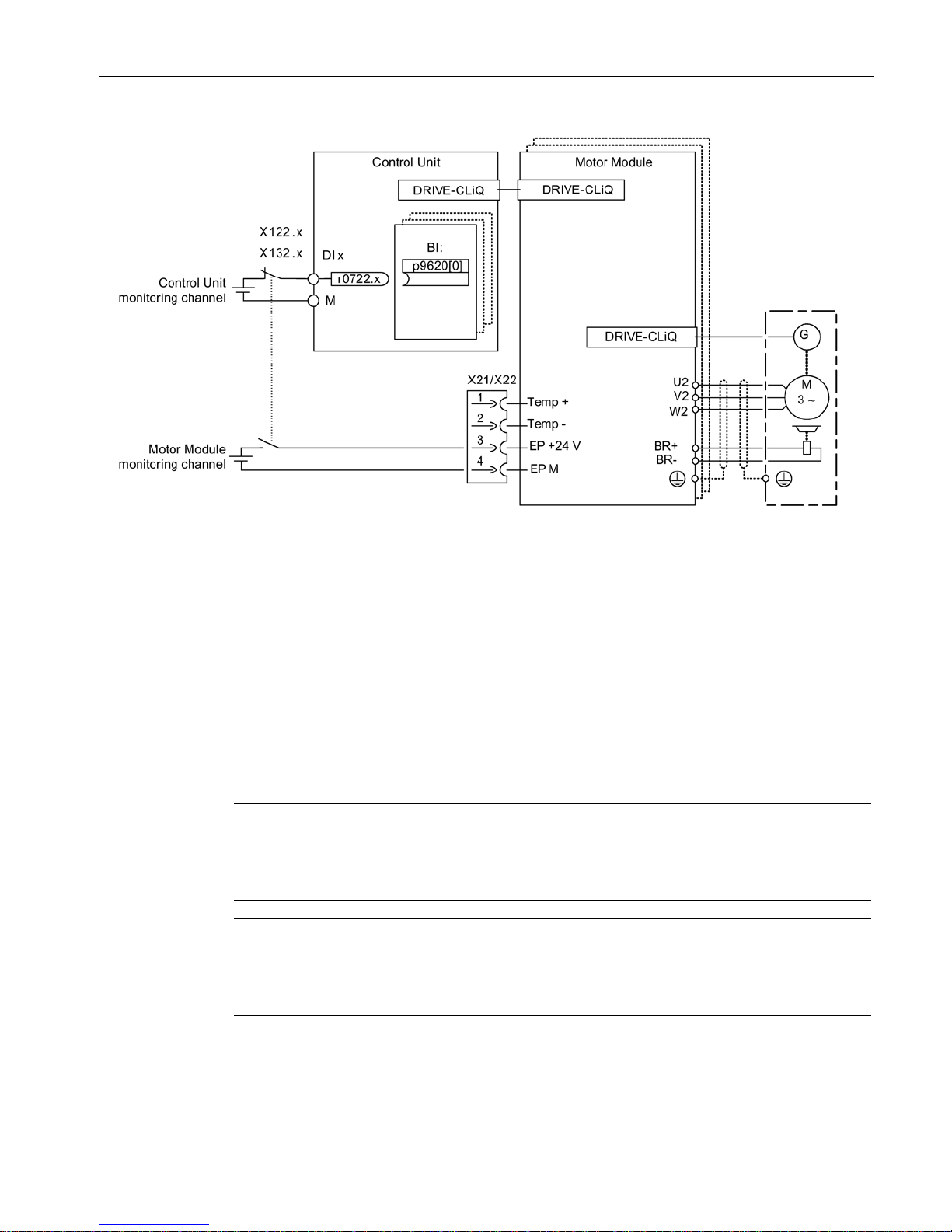
Controlling the safety functions
5.3 Control of "STO" and "SS1" via terminals on the Control Unit and the Motor/Power Module
Safety Integrated
Function Manual, 07/2016, A5E03264275A
51
Figure 5-4 Example: Terminals for "Safe Torque Off": Example of Motor Modules Booksize and CU320-2
Grouping drives
To ensure that the function works for more than one drive at the same time, the terminals for
the corresponding drives must be grouped together as follows:
1. Switch-off signal path
By appropriately interconnecting the binector input to a joint input terminal for the drives
to be combined to form a group.
2. Switch-off signal path (Motor Module / Power Module)
By appropriately wiring the terminals for the individual Motor Modules / Power Modules
belonging to the group.
Note
Parameterization of the grouping
The grouping must be configured (DI on Control Unit) and wired (EP terminals) identically in
both monitoring channels.
Note
Response of STO for grouping
If a fault in a drive results in a "Safe Torque Off" (STO), this does not automatically mean
that the other drives in the same group also switch to "Safe Torque Off" (STO).
The assignment is checked during the test for the switch-off signal paths. The operator
selects "Safe Torque Off" for each group. The check is drive-specific.
Page 52
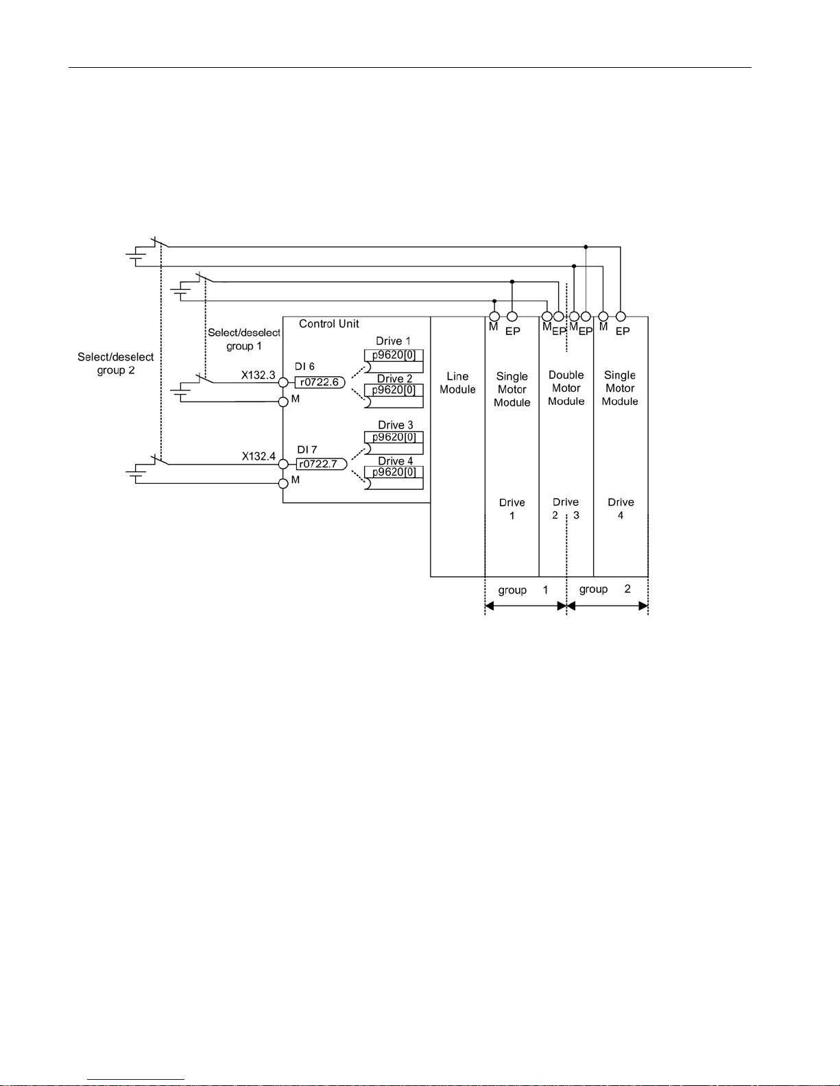
Controlling the safety functions
5.3 Control of "STO" and "SS1" via terminals on the Control Unit and the Motor/Power Module
Safety Integrated
52 Function Manual, 07/2016, A5E03264275A
Example: Terminal groups
It must be possible to select/deselect "Safe Torque Off" separately for group 1 (drives 1 and
2) and group 2 (drives 3 and 4).
For this purpose, the same grouping for "Safe Torque Off" must be realized both for the
Control Unit and the Motor Modules.
Figure 5-5 Example: Grouping terminals with Motor Modules Booksize and CU320-2
Information on the parallel connection of chassis type Motor Modules
When chassis format Motor Modules are connected in parallel, a safe AND element is
created on the parallel drive object. The number of indexes in p9620 corresponds to the
number of parallel chassis components in p0120.
Page 53

Controlling the safety functions
5.3 Control of "STO" and "SS1" via terminals on the Control Unit and the Motor/Power Module
Safety Integrated
Function Manual, 07/2016, A5E03264275A
53
5.3.1
Simultaneity and tolerance time of the two monitoring channels
The "Safe Torque Off" function must be selected/deselected simultaneously in both
monitoring channels using the input terminals and is only effective for the associated drive.
● 1 signal: Deselecting the function
● 0 signal: Selecting the function
The time delay that is unavoidable due to mechanical switching operations, for example, can
be adapted via parameters. The tolerance time, within which selection/deselection in the two
monitoring channels must occur if they are to be considered "simultaneous," is set in the
following parameters:
● p9650 (Basic Functions)
● p10002 (Extended Functions)
Note
Parameterization of the tolerance time
In order to avoid that faults
are incorrectly initiated, at these inputs the tolerance time must
always be set shorter than the shortest time between two switching events (ON/OFF,
OFF/ON).
● If the monitoring functions are not selected/deselected within the tolerance time, this is
detected by the cross-check, and the following fault (STOP F) is output.
– F01611 (Basic Functions)
– C01770 (Extended Functions)
For STO the following applies: In this case, the pulses have already been canceled as a
result of the selection of "Safe Torque Off" on one channel.
Note
Timing between the switching operations for Basic Functions
Message F01611 with fault value 1000 is output if switching operations occur too
frequently. The cause depends on the type of control:
•
The signals are continually changing at the F-DI.
•
STO is being permanently initiated via PROFIsafe (also as subsequent response).
Within the time 5
× p9650, there must be at least two switching operations at the
terminals or vi
a PROFIsafe with a minimum time between them of p9650.
Page 54

Controlling the safety functions
5.3 Control of "STO" and "SS1" via terminals on the Control Unit and the Motor/Power Module
Safety Integrated
54 Function Manual, 07/2016, A5E03264275A
● If the "Safe Stop 1" of the Basic Functions is not selected within the tolerance time in two
channels, this is detected by the cross-check, and fault F01611 (STOP F) is output. After
the set "SI Safe Stop 1 delay time" (p9652), the pulses are suppressed.
Note
To enable the drive to brake to standstill even when selected through one channel, the
time in p9652 must be shorter than the sum of the parameters for the data cross
-check
(p9650 and p9658)
. Otherwise, the drive will coast down after the time p9650 + p9658
has elapsed.
Further notes for setting the discrepancy time are contained in the List Manual for the
following messages
● F01611 (Basic Functions)
● C01770 (Extended Functions)
Overview of important parameters
•
p9650
SI SGE switchover discrepancy time (Control Unit)
•
p9652
SI Safe Stop 1 delay time (Control Unit)
•
p9658
SI transition time STOP F to STOP A (Control Unit)
•
p10002
SI Motion F
-DI switchover discrepancy time (processor 1)
Page 55
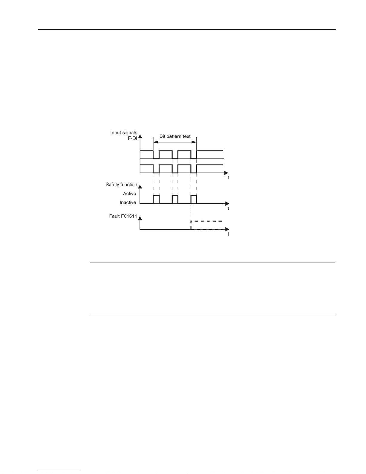
Controlling the safety functions
5.3 Control of "STO" and "SS1" via terminals on the Control Unit and the Motor/Power Module
Safety Integrated
Function Manual, 07/2016, A5E03264275A
55
5.3.2
Bit pattern test
Bit pattern test of fail-safe outputs
The converter normally responds immediately to signal changes in its fail-safe inputs. This is
not desired in the following case: Several control modules test their fail-safe outputs using bit
pattern tests (light/darkness tests) to identify faults due to either short-circuiting or cross
circuiting. When you interconnect a fail-safe input of the converter with a fail-safe output of a
control module, the converter responds to these test signals.
Figure 5-6 Converter response to a bit pattern test
Note
Debounce time for unwanted triggering of Safety Integrated functions
If the test pulses cause an unwanted triggering of the
Safety Integrated functions, these test
pulses can be suppressed using the F
-DI input filter (p9651 for Basic Functions or p10017
for Extended Functions). To do this, a value that is greater than the duration of a test pulse
must be entered in p9651 or p10
017.
Overview of important parameters
•
p9651
SI STO/SBC/SS1 debounce time (Control Unit)
•
p10017
SI Motion digital inputs debounce time (processor 1)
Page 56

Controlling the safety functions
5.3 Control of "STO" and "SS1" via terminals on the Control Unit and the Motor/Power Module
Safety Integrated
56 Function Manual, 07/2016, A5E03264275A
5.3.3
Control of "STO" and "SS1" for SINAMICS G130
Description
The safety functions contained in the standard ("Safe Torque Off" and "Safe Stop 1") can be
used with the Power Module.
Note
Refer to the circuit diagrams enclosed for the interconnections of your device.
Note
The Safety functions must be activated prior to use via parameter assignment. An
acc
eptance test must be performed and an acceptance log must be created.
The following Safety Integrated Basic Functions (terms according to DIN EN 61800-5-2) can
be activated:
● Safe Torque Off (STO)
● Safe Stop 1 (SS1) (time-controlled)
Note
The integrat
ed safety functions, starting from the Safety Integrated (SI) input terminals of the
SINAMICS components (Control Unit, Power Module), satisfy the requirements of
EN
61800-5-2, EN 60204-1 and DIN EN ISO 13849-1 category 3 (formerly EN 954-1), as
well as th
e requirements for Performance Level (PL) d and IEC 61508 SIL2.
In addition, most of the SINAMICS safety functions have been certified by independent
institutes. A list of currently certified components is available on request from your local
Siemens office.
Recommended application
This variant is used when:
● Activation will be executed optically isolated with a voltage of 24 VDC.
● Working with control lines that are shorter than 30 m.
● Devices are deployed in plants with low spatial elongation
(observe the drop in voltage at 24 VDC!).
Page 57
Controlling the safety functions
5.3 Control of "STO" and "SS1" via terminals on the Control Unit and the Motor/Power Module
Safety Integrated
Function Manual, 07/2016, A5E03264275A
57
Principle of operation
The first shutdown path for the integrated safety functions is activated via a digital input on
the Control Unit. Digital inputs DI 0 to DI 7, DI 16, DI 17, DI 20 and DI 21 are available for
this purpose.
The second shutdown path for the integrated safety functions is activated via the terminals (X41:1, -X42:2) on the Control Interface Module of the Power Module.
The selection and deselection must be simultaneous. The time delay that is unavoidable due
to mechanical switching processes, for example, can be adapted via parameters. p9650
specifies the tolerance time within which the selection/deselection of the two monitoring
channels must occur in order to be considered as "simultaneous".
The selection of the safety function on the Control Unit and on the Control Interface Module
of the Power Module must be performed in two channels. A switch according to ISO 13850/
EN 418, positive opening according to EC 60947-5-1, or a certified safety controller must be
used as actuating element.
WARNING
Danger to life as a result of failure of the safety functions through unsuitable selection of the
actuating element
An unsuitable actuating element may cause the safety function to fail which can result in
death or serious injury.
• Select the correct actuating element for the purpose of compliance of the overall system
with the required standard (DIN EN ISO 13849-1 (formerly EN954-1) Cat. 3 PL d or DIN
EN 61508 SIL2).
Terminal strip –X41 on the Control Interface Module of the Power Module
Table 5- 6 Terminal strip –X41 on the Control Interface Module of the Power Module
Terminal
Function
Technical data
-X41:2
EP +24 V (enable pulses)
Supply voltage: 24 VDC (20.4 ... 28.8 V)
Power consumption: 10 mA
-X41:1
EP M1 (enable pulses)
Page 58
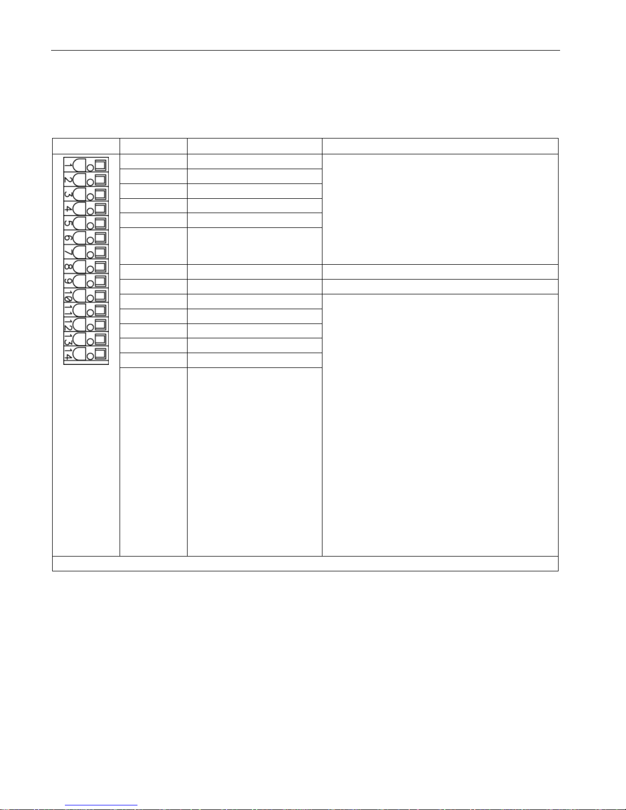
Controlling the safety functions
5.3 Control of "STO" and "SS1" via terminals on the Control Unit and the Motor/Power Module
Safety Integrated
58 Function Manual, 07/2016, A5E03264275A
Terminal strip –X122 on the CU320-2 Control Unit
Table 5- 7 Terminal strip –X122 on the CU320-2 Control Unit
Terminal
Designation 1)
Technical data
1
DI 0
Voltage: -30 ... +30 VDC
Typical power consumption: 9 mA at 24 V
Electrical isolation: Reference potential is terminal M1
Level (incl. ripple)
High level: 15 … 30 V
Low-level: -30 … +5 V
Input delay (typ.):
For "0" → "1": 50 μs
For "1" → "0": 150 μs
2 DI 1
3
DI 2
4
DI 3
5
DI 16
6 DI 17
7
M1
Reference potential for terminals 1 ... 6
8 M Ground
9
DI/DO 8
As input
:
Voltage: -30 ... +30 VDC
Typical power consumption: 9 mA at 24 V
Level (incl. ripple)
High level: 15 … 30 V
Low-level: -30 … +5 V
DI/DO 8, 9, 10, and 11 are "rapid inputs"
2)
Input delay (typ.):
For "0" → "1": 5 μs
For "1" → "0": 50 μs
As output
:
Voltage: 24 V DC
Max. load current per output: 500 mA
Continuous short-circuit proof
Output delay (typ./max.)
3)
:
For "0" → "1": 150 μs / 400 μs
For "1" → "0": 75 μs / 100 μs
Switching frequency:
For resistive load: Max. 100 Hz
For inductive load: Max. 0.5 Hz
For lamp load: Max. 10 Hz
Maximum lamp load: 5 W
10
DI/DO 9
11
M
12
DI/DO 10
13
DI/DO 11
14 M
Max. connectable cross-section: 1.5 mm2
1)
DI: Digital input; DI/DO: Bidirectional digital input/output; M: Electronics ground; M1: Reference ground
2)
The rapid inputs can be used as probe inputs or as inputs for the external zero mark
3)
Data for: Vcc = 24 V; Load 48 Ω; High ("1") = 90% V
out
; Low ("0") = 10% V
out
Page 59

Controlling the safety functions
5.3 Control of "STO" and "SS1" via terminals on the Control Unit and the Motor/Power Module
Safety Integrated
Function Manual, 07/2016, A5E03264275A
59
Note
An open input is interpreted as "low".
To enable the digital inputs (DI) to function, terminal M1 must be connected.
This is achieved by:
1.
Providing the ground reference of the digital inputs, or
2.
A jumper to terminal M.
This removes isolation for these digital inputs.
Note
If the 24
V supply is briefly interrupted, the digital outputs are deactivated for this time.
Page 60
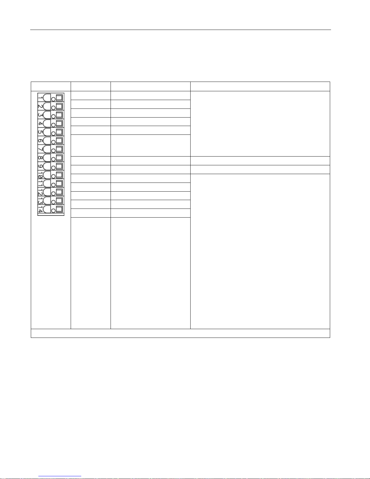
Controlling the safety functions
5.3 Control of "STO" and "SS1" via terminals on the Control Unit and the Motor/Power Module
Safety Integrated
60 Function Manual, 07/2016, A5E03264275A
Terminal strip –X132 on the CU320-2 Control Unit
Table 5- 8 Terminal strip –X132 on the CU320-2 Control Unit
Terminal
Designation 1)
Technical data
1
DI 4
Voltage: -30 ... +30 VDC
Typical power consumption: 9 mA at 24 V
Electrical isolation: Reference potential is terminal M2
Level (incl. ripple)
High level: 15 … 30 V
Low-level: -30 … +5 V
Input delay (typ.):
For "0" → "1": 50 μs
For "1" → "0": 150 μs
2 DI 5
3
DI 6
4
DI 7
5
DI 20
6 DI 21
7
M2
Reference potential for terminals 1 ... 6
8 M Ground
9
DI/DO 12
As input
:
Voltage: -30 ... +30 VDC
Typical power consumption: 9 mA at 24 V
Level (incl. ripple)
High level: 15 … 30 V
Low-level: -30 … +5 V
DI/DO 12, 13, 14, and 15 are "rapid inputs"
2)
Input delay (typ.):
For "0" → "1": 5 μs
For "1" → "0": 50 μs
As output
:
Voltage: 24 V DC
Max. load current per output: 500 mA
Continuous short-circuit proof
Output delay (typ./max.)
3)
:
For "0" → "1": 150 μs / 400 μs
For "1" → "0": 75 μs / 100 μs
Switching frequency:
For resistive load: Max. 100 Hz
For inductive load: Max. 0.5 Hz
For lamp load: Max. 10 Hz
Maximum lamp load: 5 W
10
DI/DO 13
11
M
12
DI/DO 14
13
DI/DO 15
14 M
Max. connectable cross-section: 1.5 mm2
1)
DI: Digital input; DI/DO: Bidirectional digital input/output; M: Electronics ground; M2: Reference ground
2)
The rapid inputs can be used as probe inputs or as inputs for the external zero mark
3)
Data for: Vcc = 24 V; Load 48 Ω; High ("1") = 90% V
out
; Low ("0") = 10% V
out
Page 61

Controlling the safety functions
5.3 Control of "STO" and "SS1" via terminals on the Control Unit and the Motor/Power Module
Safety Integrated
Function Manual, 07/2016, A5E03264275A
61
Note
An open input is interpreted as "low".
To enable the digital inputs (DI) to function, terminal M2 must be connected.
This is achieved by:
1.
Providing the ground reference of the digital inputs, or
2.
A jumper to terminal M.
This removes isolation for these digital inputs.
Note
If the 24
V supply is briefly interrupted, the digital outputs are deactivated for this time.
Wiring
The control cables should be permanently routed (e.g. cable duct, retained using cable ties).
Signal cables and encoder cables should be installed separated from one another.
The shields of the control cables should be grounded through the largest possible surface
area immediately after they enter the control cabinet.
Outside the control cabinet, the cables must be routed in such a way that they are safe to
walk on (e.g. as specified in IEC 60204-1).
Page 62

Controlling the safety functions
5.3 Control of "STO" and "SS1" via terminals on the Control Unit and the Motor/Power Module
Safety Integrated
62 Function Manual, 07/2016, A5E03264275A
5.3.4
Control of "STO" and "SS1" for SINAMICS G150
Description
The safety functions contained in the standard ("Safe Torque Off" and "Safe Stop 1") can
also be used without option K82.
Note
Refer to the circuit diagrams enclosed for the interconnections of your device.
Note
The Safety functions must be activated prior to use via parameter assignment. An
acceptance test must be perfor
med and an acceptance log must be created.
The following Safety Integrated Basic Functions (terms and definitions according to IEC
61800-5-2) can be activated:
● Safe Torque Off (STO)
● Safe Stop 1 (SS1) (time-controlled)
Note
The integrated safety func
tions, starting from the Safety Integrated (SI) input terminals of the
SINAMICS components (Control Unit, Power Module), satisfy the requirements of
EN
61800-5-2, EN 60204-1 and DIN EN ISO 13849-1 category 3 (formerly EN 954-1), as
well as the requirements
for Performance Level (PL) d and IEC 61508 SIL2.
In addition, most of the SINAMICS safety functions have been certified by independent
institutes. A list of currently certified components is available on request from your local
Siemens office.
Recommended application
This variant is used when:
● Activation will be executed optically isolated with a voltage of 24 VDC.
● Working with control lines that are shorter than 30 m.
● Devices are deployed in plants with low spatial elongation (observe the drop in voltage at
24 VDC!).
Principle of operation
The first shutdown path for the integrated safety functions is activated via a digital input on
the Control Unit. Digital inputs DI 0 to DI 7, DI 16, DI 17, DI 20 and DI 21 are available for
this purpose.
The second shutdown path for the integrated safety functions is activated via the terminals (X41:1, -X42:2) on the Control Interface Module of the Power Module.
Page 63
Controlling the safety functions
5.3 Control of "STO" and "SS1" via terminals on the Control Unit and the Motor/Power Module
Safety Integrated
Function Manual, 07/2016, A5E03264275A
63
Note
Additional inputs must be activated for the following cabinet units (synchronizers):
•
An additional digital input on the CU320-2 and
•
The terminals (-X41:1, -X42:2) on the Control Interface Module of the second Power
Module connected in parallel.
Synchronizers:
•
For 380 to 480 V 3 AC:
6SL3710-2GE41-1AAx, 6SL3710-2GE41-4AAx, 6SL3710-2GE41-6AAx
•
For 500 to 600 V 3 AC:
6SL3710-2GF38-6AAx, 6SL3710-2GF41-1AAx, 6SL3710-2GF41-4AAx
•
For 660 to 690 V 3 AC:
6SL3710-2GH41-1AAx, 6SL3710-2GH41-4AAx, 6SL3710-2GH41-5AAx
The selection and deselection must be simultaneous. The time delay that is unavoidable due
to mechanical switching processes, for example, can be adapted via parameters. p9650
specifies the tolerance time within which the selection/deselection of the two monitoring
channels must occur in order to be considered as "simultaneous".
The selection of the safety function on the Control Unit and on the Control Interface Module
of the Power Module must be executed over two channels. A switch according to ISO 13850/
EN 418, positive opening according to EC 60947-5-1, or a certified safety controller must be
used as actuating element.
WARNING
Danger to life as a result of failure of the safety functions through unsuitable selection of the
actuating element
An unsuitable actuating element may cause the safety function to fail which can result in
death or serious injury.
• Select the correct actuating element for the purpose of compliance of the overall system
with the required standard (DIN EN ISO 13849-1 (formerly EN954-1) Cat. 3 PL d or DIN
EN 61508 SIL2).
Terminal strip –X41 on the Control Interface Module of the Power Module
Table 5- 9 Terminal strip –X41 on the Control Interface Module of the Power Module
Terminal
Function
Technical data
-X41:2
EP +24 V (enable pulses)
Supply voltage: 24 VDC (20.4 ... 28.8 V)
Power consumption: 10 mA
-X41:1
EP M1 (enable pulses)
Page 64
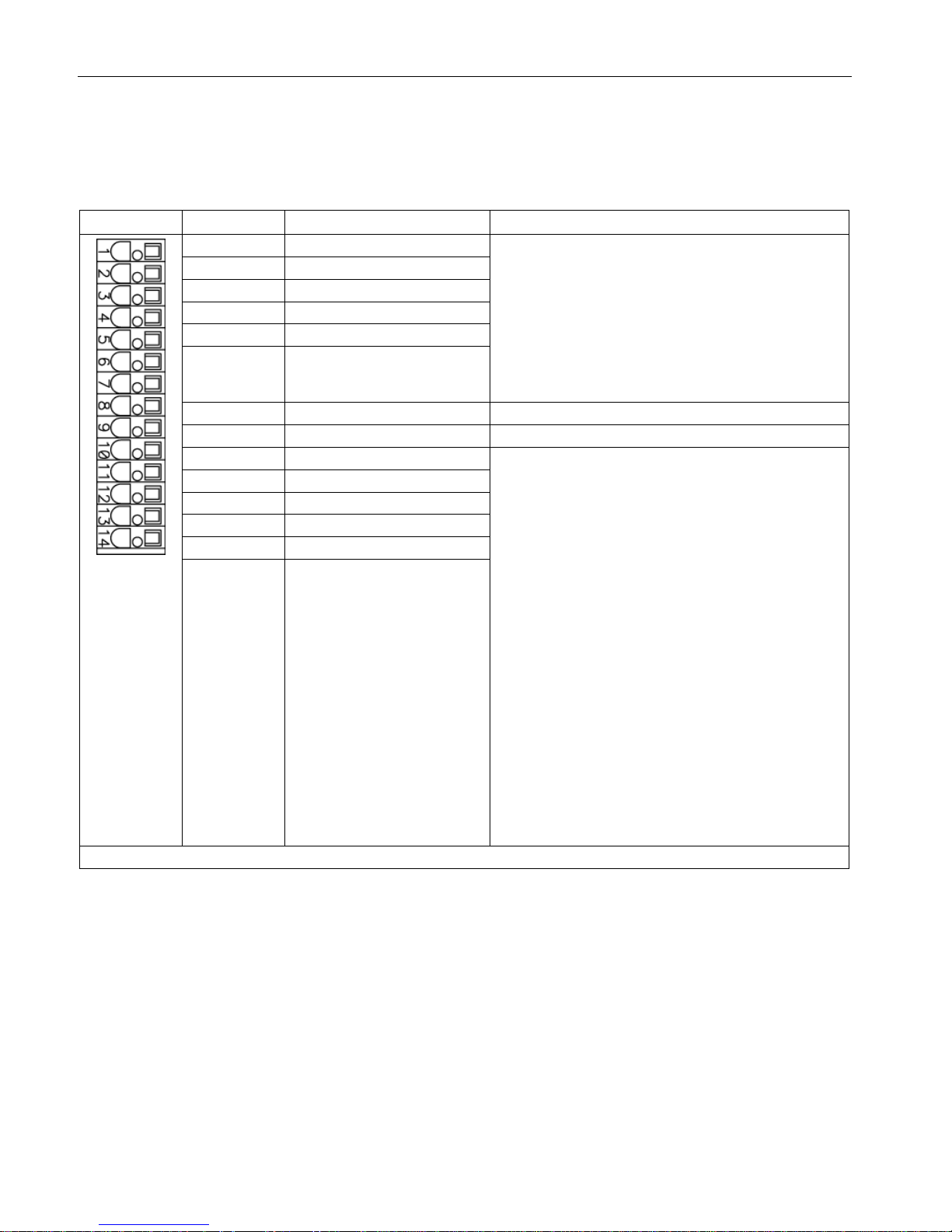
Controlling the safety functions
5.3 Control of "STO" and "SS1" via terminals on the Control Unit and the Motor/Power Module
Safety Integrated
64 Function Manual, 07/2016, A5E03264275A
Terminal strip –X122 on the CU320-2 Control Unit
Table 5- 10 Terminal strip –X122 on the CU320-2 Control Unit
Terminal
Designation 1)
Technical data
1
DI 0
Voltage: -30 ... +30 VDC
Typical power consumption: 9 mA at 24 V
Electrical isolation: Reference potential is terminal M1
Level (incl. ripple)
High level: 15 … 30 V
Low-level: -30 … +5 V
Input delay (typ.):
For "0" → "1": 50 μs
For "1" → "0": 150 μs
2 DI 1
3
DI 2
4
DI 3
5
DI 16
6 DI 17
7
M1
Reference potential for terminals 1 ... 6
8 M Ground
9
DI/DO 8
As input
:
Voltage: -30 ... +30 VDC
Typical power consumption: 9 mA at 24 V
Level (incl. ripple)
High level: 15 … 30 V
Low-level: -30 … +5 V
DI/DO 8, 9, 10, and 11 are "rapid inputs"
2)
Input delay (typ.):
For "0" → "1": 5 μs
For "1" → "0": 50 μs
As output
:
Voltage: 24 V DC
Max. load current per output: 500 mA
Continuous short-circuit proof
Output delay (typ./max.)
3)
:
For "0" → "1": 150 μs / 400 μs
For "1" → "0": 75 μs / 100 μs
Switching frequency:
For resistive load: Max. 100 Hz
For inductive load: Max. 0.5 Hz
For lamp load: Max. 10 Hz
Maximum lamp load: 5 W
10
DI/DO 9
11
M
12
DI/DO 10
13
DI/DO 11
14 M
Max. connectable cross-section: 1.5 mm2
1)
DI: Digital input; DI/DO: Bidirectional digital input/output; M: Electronics ground; M1: Reference ground
2)
The rapid inputs can be used as probe inputs or as inputs for the external zero mark
3)
Data for: Vcc = 24 V; Load 48 Ω; High ("1") = 90% V
out
; Low ("0") = 10% V
out
Page 65

Controlling the safety functions
5.3 Control of "STO" and "SS1" via terminals on the Control Unit and the Motor/Power Module
Safety Integrated
Function Manual, 07/2016, A5E03264275A
65
Note
An open input is interpreted as "low".
To enable the digital inputs (DI) to function, terminal M1 must be connected.
This is achieved by:
1.
Providing the ground reference of the digital inputs, or
2.
A jumper to terminal M.
This removes isolation for these digital inputs.
Note
If the 24
V supply is briefly interrupted, the digital outputs are deactivated for this time.
Page 66
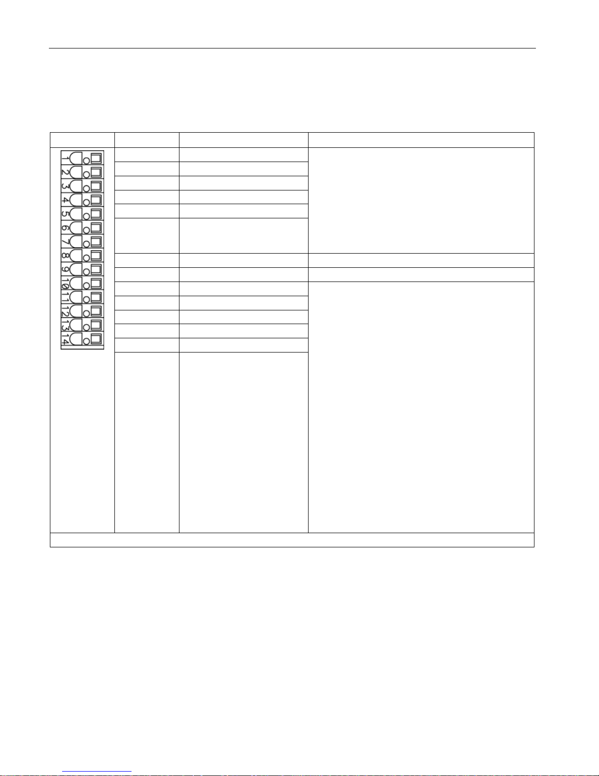
Controlling the safety functions
5.3 Control of "STO" and "SS1" via terminals on the Control Unit and the Motor/Power Module
Safety Integrated
66 Function Manual, 07/2016, A5E03264275A
Terminal strip –X132 on the CU320-2 Control Unit
Table 5- 11 Terminal strip –X132 on the CU320-2 Control Unit
Terminal
Designation 1)
Technical data
1
DI 4
Voltage: -30 ... +30 VDC
Typical power consumption: 9 mA at 24 V
Electrical isolation: Reference potential is terminal M2
Level (incl. ripple)
High level: 15 … 30 V
Low-level: -30 … +5 V
Input delay (typ.):
For "0" → "1": 50 μs
For "1" → "0": 150 μs
2 DI 5
3
DI 6
4
DI 7
5
DI 20
6 DI 21
7
M2
Reference potential for terminals 1 ... 6
8 M Ground
9
DI/DO 12
As input
:
Voltage: -30 ... +30 VDC
Typical power consumption: 9 mA at 24 V
Level (incl. ripple)
High level: 15 … 30 V
Low-level: -30 … +5 V
DI/DO 12, 13, 14, and 15 are "rapid inputs"
2)
Input delay (typ.):
For "0" → "1": 5 μs
For "1" → "0": 50 μs
As output
:
Voltage: 24 V DC
Max. load current per output: 500 mA
Continuous short-circuit proof
Output delay (typ./max.)
3)
:
For "0" → "1": 150 μs / 400 μs
For "1" → "0": 75 μs / 100 μs
Switching frequency:
For resistive load: Max. 100 Hz
For inductive load: Max. 0.5 Hz
For lamp load: Max. 10 Hz
Maximum lamp load: 5 W
10
DI/DO 13
11
M
12
DI/DO 14
13
DI/DO 15
14 M
Max. connectable cross-section: 1.5 mm2
1)
DI: Digital input; DI/DO: Bidirectional digital input/output; M: Electronics ground; M2: Reference ground
2)
The rapid inputs can be used as probe inputs or as inputs for the external zero mark
3)
Data for: Vcc = 24 V; Load 48 Ω; High ("1") = 90% V
out
; Low ("0") = 10% V
out
Page 67

Controlling the safety functions
5.3 Control of "STO" and "SS1" via terminals on the Control Unit and the Motor/Power Module
Safety Integrated
Function Manual, 07/2016, A5E03264275A
67
Note
An open input is interpreted as "low".
To enable the digital inputs (DI) to function, terminal M2 must be connected.
This is achieved by:
1.
Providing the ground reference of the digital inputs, or
2.
A jumper to terminal M.
This removes isolation for these digital inputs.
Note
If the 24
V supply is briefly interrupted, the digital outputs are deactivated for this time.
Wiring
The control cables should be permanently routed (e.g. cable duct, retained using cable ties).
Signal cables and encoder cables should be installed separated from one another.
The shields of the control cables should be grounded through the largest possible surface
area immediately after they enter the control cabinet.
Outside the control cabinet, the cables must be routed in such a way that they are safe to
walk on (e.g. as specified in IEC 60204-1).
Page 68

Controlling the safety functions
5.3 Control of "STO" and "SS1" via terminals on the Control Unit and the Motor/Power Module
Safety Integrated
68 Function Manual, 07/2016, A5E03264275A
5.3.5
Control of "STO" and "SS1" for SINAMICS S120 Chassis
Description
The safety functions contained in the standard ("Safe Torque Off" and "Safe Stop 1") can be
used with the Motor Module.
Note
Refer to the circuit diagrams enclosed for the interconnections of your device.
Note
The Safety functions must be activated prior to use via parameter assignment. An
acceptance test must be
performed and an acceptance log must be created.
The following Safety Integrated Basic Functions (terms according to DIN EN 61800-5-2) can
be activated:
● Safe Torque Off (STO)
● Safe Stop 1 (SS1) (time-controlled)
Note
The integrated safety functions,
starting from the Safety Integrated (SI) input terminals of the
SINAMICS components (Control Unit, Motor Module), satisfy the requirements of
EN
61800-5-2, EN 60204-1, and DIN EN ISO 13849-1 category 3 (formerly EN 954-1), as
well as the requirements for P
erformance Level (PL) d and IEC 61508 SIL2.
In addition, most of the SINAMICS safety functions have been certified by independent
institutes. A list of currently certified components is available on request from your local
Siemens office.
Recommended application
This variant is used when:
● Activation will be executed optically isolated with a voltage of 24 VDC.
● Working with control lines that are shorter than 30 m.
● Devices are deployed in plants with low spatial elongation (observe the drop in voltage at
24 VDC!).
Page 69
Controlling the safety functions
5.3 Control of "STO" and "SS1" via terminals on the Control Unit and the Motor/Power Module
Safety Integrated
Function Manual, 07/2016, A5E03264275A
69
Principle of operation
The first shutdown path for the integrated safety functions is activated via a digital input on
the Control Unit. Digital inputs DI 0 to DI 7, DI 16, DI 17, DI 20 and DI 21 are available for
this purpose.
The second shutdown path for the integrated safety functions is activated using the terminals
(-X41:1, -X42:2) on the Control Interface Module of the Motor Module.
The selection and deselection must be simultaneous. The time delay that is unavoidable due
to mechanical switching processes, for example, can be adapted via parameters. p9650
specifies the tolerance time within which the selection/deselection of the two monitoring
channels must occur in order to be considered as "simultaneous".
The selection of the safety function on the Control Unit and on the Motor Module must be
executed over two channels. A switch according to ISO 13850/ EN 418, positive opening
according to EC 60947-5-1, or a certified safety controller must be used as actuating
element.
WARNING
Danger to life as a result of failure of the safety functions through unsuitable selection of the
actuating element
An unsuitable actuating element may cause the safety function to fail which can result in
death or serious injury.
• Select the correct actuating element for the purpose of compliance of the overall system
with the required standard (DIN EN ISO 13849-1 (formerly EN954-1) Cat. 3 PL d or DIN
EN 61508 SIL2).
Terminal strip –X41 on the Control Interface Module of the chassis Motor Module
Table 5- 12 Terminal strip –X41 on the Control Interface Module of the chassis Motor Module
Terminal
Function
Technical data
-X41:2
EP +24 V (enable pulses)
Supply voltage: 24 VDC (20.4 ... 28.8 V)
Power consumption: 10 mA
-X41:1
EP M1 (enable pulses)
Page 70
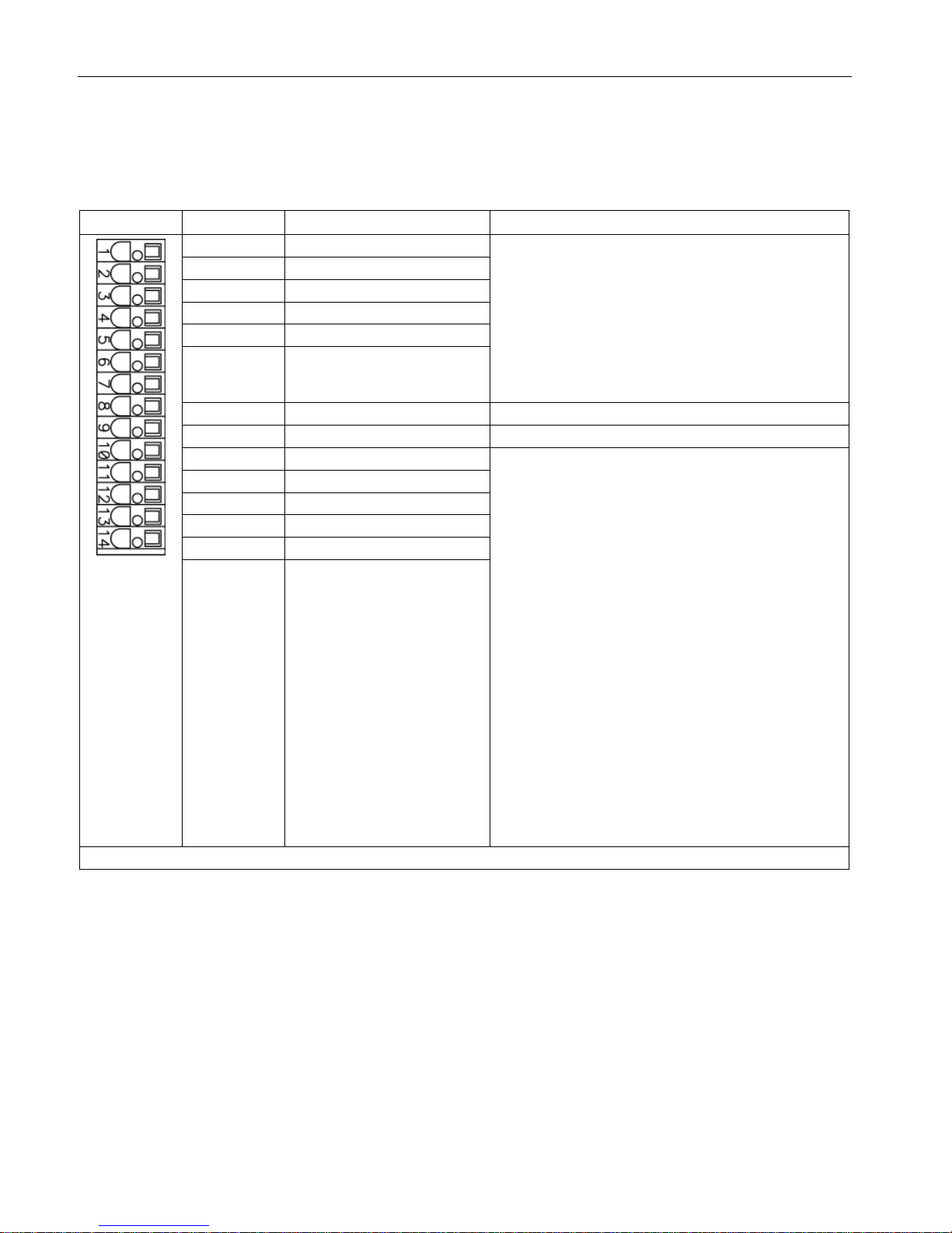
Controlling the safety functions
5.3 Control of "STO" and "SS1" via terminals on the Control Unit and the Motor/Power Module
Safety Integrated
70 Function Manual, 07/2016, A5E03264275A
Terminal strip –X122 on the CU320-2 Control Unit
Table 5- 13 Terminal strip –X122 on the CU320-2 Control Unit
Terminal
Designation 1)
Technical data
1
DI 0
Voltage: -30 ... +30 VDC
Typical power consumption: 9 mA at 24 V
Electrical isolation: Reference potential is terminal M1
Level (incl. ripple)
High level: 15 … 30 V
Low-level: -30 … +5 V
Input delay (typ.):
For "0" → "1": 50 μs
For "1" → "0": 150 μs
2 DI 1
3
DI 2
4
DI 3
5
DI 16
6 DI 17
7
M1
Reference potential for terminals 1 ... 6
8 M Ground
9
DI/DO 8
As input
:
Voltage: -30 ... +30 VDC
Typical power consumption: 9 mA at 24 V
Level (incl. ripple)
High level: 15 … 30 V
Low-level: -30 … +5 V
DI/DO 8, 9, 10, and 11 are "rapid inputs"
2)
Input delay (typ.):
For "0" → "1": 5 μs
For "1" → "0": 50 μs
As output
:
Voltage: 24 V DC
Max. load current per output: 500 mA
Continuous short-circuit proof
Output delay (typ./max.)
3)
:
For "0" → "1": 150 μs / 400 μs
For "1" → "0": 75 μs / 100 μs
Switching frequency:
For resistive load: Max. 100 Hz
For inductive load: Max. 0.5 Hz
For lamp load: Max. 10 Hz
Maximum lamp load: 5 W
10
DI/DO 9
11
M
12
DI/DO 10
13
DI/DO 11
14 M
Max. connectable cross-section: 1.5 mm2
1)
DI: Digital input; DI/DO: Bidirectional digital input/output; M: Electronics ground; M1: Reference ground
2)
The rapid inputs can be used as probe inputs or as inputs for the external zero mark
3)
Data for: Vcc = 24 V; Load 48 Ω; High ("1") = 90% V
out
; Low ("0") = 10% V
out
Page 71

Controlling the safety functions
5.3 Control of "STO" and "SS1" via terminals on the Control Unit and the Motor/Power Module
Safety Integrated
Function Manual, 07/2016, A5E03264275A
71
Note
An open input is interpreted as "low".
To enable the digital inputs (DI) to function, terminal M1 must be connected.
This is achieved by:
1.
Providing the ground reference of the digital inputs, or
2.
A jumper to terminal M.
This removes isolation for these digital inputs.
Note
If the 24
V supply is briefly interrupted, the digital outputs are deactivated for this time.
Page 72
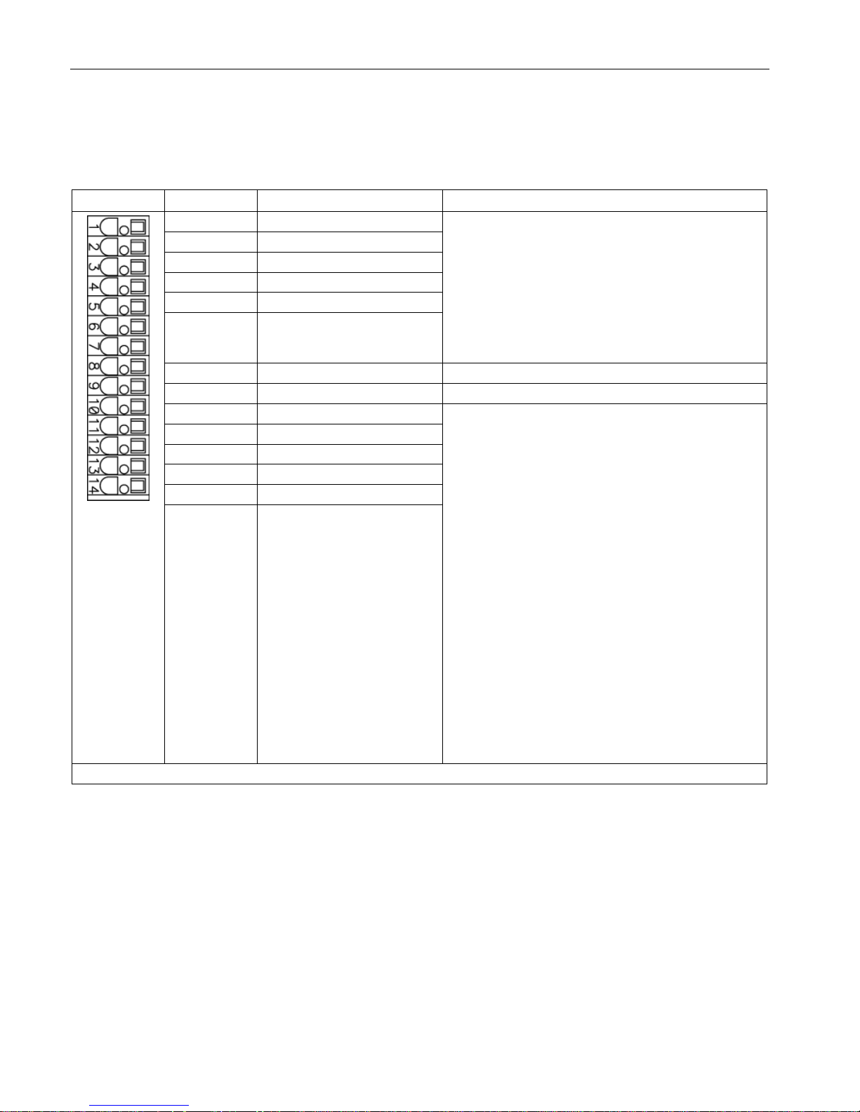
Controlling the safety functions
5.3 Control of "STO" and "SS1" via terminals on the Control Unit and the Motor/Power Module
Safety Integrated
72 Function Manual, 07/2016, A5E03264275A
Terminal strip –X132 on the CU320-2 Control Unit
Table 5- 14 Terminal strip –X132 on the CU320-2 Control Unit
Terminal
Designation 1)
Technical data
1
DI 4
Voltage: -30 ... +30 VDC
Typical power consumption: 9 mA at 24 V
Electrical isolation: Reference potential is terminal M2
Level (incl. ripple)
High level: 15 … 30 V
Low-level: -30 … +5 V
Input delay (typ.):
For "0" → "1": 50 μs
For "1" → "0": 150 μs
2 DI 5
3
DI 6
4
DI 7
5
DI 20
6 DI 21
7
M2
Reference potential for terminals 1 ... 6
8 M Ground
9
DI/DO 12
As input
:
Voltage: -30 ... +30 VDC
Typical power consumption: 9 mA at 24 V
Level (incl. ripple)
High level: 15 … 30 V
Low-level: -30 … +5 V
DI/DO 12, 13, 14, and 15 are "rapid inputs"
2)
Input delay (typ.):
For "0" → "1": 5 μs
For "1" → "0": 50 μs
As output
:
Voltage: 24 V DC
Max. load current per output: 500 mA
Continuous short-circuit proof
Output delay (typ./max.)
3)
:
For "0" → "1": 150 μs / 400 μs
For "1" → "0": 75 μs / 100 μs
Switching frequency:
For resistive load: Max. 100 Hz
For inductive load: Max. 0.5 Hz
For lamp load: Max. 10 Hz
Maximum lamp load: 5 W
10
DI/DO 13
11
M
12
DI/DO 14
13
DI/DO 15
14 M
Max. connectable cross-section: 1.5 mm2
1)
DI: Digital input; DI/DO: Bidirectional digital input/output; M: Electronics ground; M2: Reference ground
2)
The rapid inputs can be used as probe inputs or as inputs for the external zero mark
3)
Data for: Vcc = 24 V; Load 48 Ω; High ("1") = 90% V
out
; Low ("0") = 10% V
out
Page 73

Controlling the safety functions
5.3 Control of "STO" and "SS1" via terminals on the Control Unit and the Motor/Power Module
Safety Integrated
Function Manual, 07/2016, A5E03264275A
73
Note
An open input is interpreted as "low".
To enable the digital inputs (DI) to function, terminal M2 must be connected.
This is achieved by:
1.
Providing the ground reference of the digital inputs, or
2.
A jumper to terminal M.
This removes isolation for these digital inputs.
Note
If the 24
V supply is briefly interrupted, the digital outputs are deactivated for this time.
Wiring
The control cables should be permanently routed (e.g. cable duct, retained using cable ties).
Signal cables and encoder cables should be installed separated from one another.
The shields of the control cables should be grounded through the largest possible surface
area immediately after they enter the control cabinet.
Outside the control cabinet, the cables must be routed in such a way that they are safe to
walk on (e.g. as specified in IEC 60204-1).
Page 74

Controlling the safety functions
5.3 Control of "STO" and "SS1" via terminals on the Control Unit and the Motor/Power Module
Safety Integrated
74 Function Manual, 07/2016, A5E03264275A
5.3.6
Control of "STO" and "SS1" for SINAMICS S120 Cabinet Modules
Description
The safety functions contained in the standard ("Safe Torque Off" and "Safe Stop 1") can
also be used without option K82.
Note
Refer to the circuit diagrams enclosed for the interconnections of your device.
Note
The Safety functions must be activated prior to use via parameter assignment. An
acceptance tes
t must be performed and an acceptance log must be created.
The following Safety Integrated Basic Functions (terms according to DIN EN 61800-5-2) can
be activated:
● Safe Torque Off (STO)
● Safe Stop 1 (SS1) (time-controlled)
Note
The integrated safety f
unctions, starting from the Safety Integrated (SI) input terminals of the
SINAMICS components (Control Unit, Motor Module), satisfy the requirements of
EN
61800-5-2, EN 60204-1, and DIN EN ISO 13849-1 category 3 (formerly EN 954-1), as
well as the requirem
ents for Performance Level (PL) d and IEC 61508 SIL2.
In addition, most of the SINAMICS safety functions have been certified by independent
institutes. A list of currently certified components is available on request from your local
Siemens office.
Recommended application
This variant is used when:
● Activation will be executed optically isolated with a voltage of 24 VDC.
● Working with control lines that are shorter than 30 m.
● Devices are deployed in plants with low spatial elongation (observe the drop in voltage at
24 VDC!).
Principle of operation
The first shutdown path for the integrated safety functions is activated via a digital input on
the Control Unit. Digital inputs DI 0 to DI 7, DI 16, DI 17, DI 20 and DI 21 are available for
this purpose.
Page 75
Controlling the safety functions
5.3 Control of "STO" and "SS1" via terminals on the Control Unit and the Motor/Power Module
Safety Integrated
Function Manual, 07/2016, A5E03264275A
75
Chassis Motor Module
● The second shutdown path for the integrated safety functions is activated using the
terminals (-X41:1, -X42:2) on the Control Interface Module of the Motor Module.
Booksize Cabinet Kit
● The second shutdown path for the integrated safety functions is activated using the
terminals (-X21:3, -X21:4) on the Motor Module Booksize.
The selection and deselection must be simultaneous. The time delay that is unavoidable due
to mechanical switching processes, for example, can be adapted via parameters. p9650
specifies the tolerance time within which the selection/deselection of the two monitoring
channels must occur in order to be considered as "simultaneous".
The selection of the safety function on the Control Unit and on the Motor Module must be
executed over two channels. A switch according to ISO 13850/ EN 418, positive opening
according to EC 60947-5-1, or a certified safety controller must be used as actuating
element.
WARNING
Danger to life as a result of failure of the safety functions through unsuitable selection of the
actuating element
An unsuitable actuating element may cause the safety function to fail which can result in
death or serious injury.
• Select the correct actuating element for the purpose of compliance of the overall system
with the required standard (DIN EN ISO 13849-1 (formerly EN954-1) Cat. 3 PL d or DIN
EN 61508 SIL2).
Terminal strip –X41 on the Control Interface Module of the chassis Motor Module
Table 5- 15 Terminal strip –X41 on the Control Interface Module of the chassis Motor Module
Terminal
Function
Technical data
-X41:2
EP +24 V (enable pulses)
Supply voltage: 24 VDC (20.4 ... 28.8 V)
Power consumption: 10 mA
-X41:1
EP M1 (enable pulses)
Terminal strip –X21/–X22 on the Motor Module Booksize
Table 5- 16 Terminal strip –X21/–X22 on the Motor Module Booksize
Terminal
Function
Technical data
-X21:3
-X22:3
EP +24 V (enable pulses) Supply voltage: 24 VDC (20.4 ... 28.8 V)
Power consumption: 10 mA
Signal propagation times:
L → H: 100 µs
H → L: 1000 µs
-X21:4
-X22:4
EP M1 (enable pulses)
Page 76
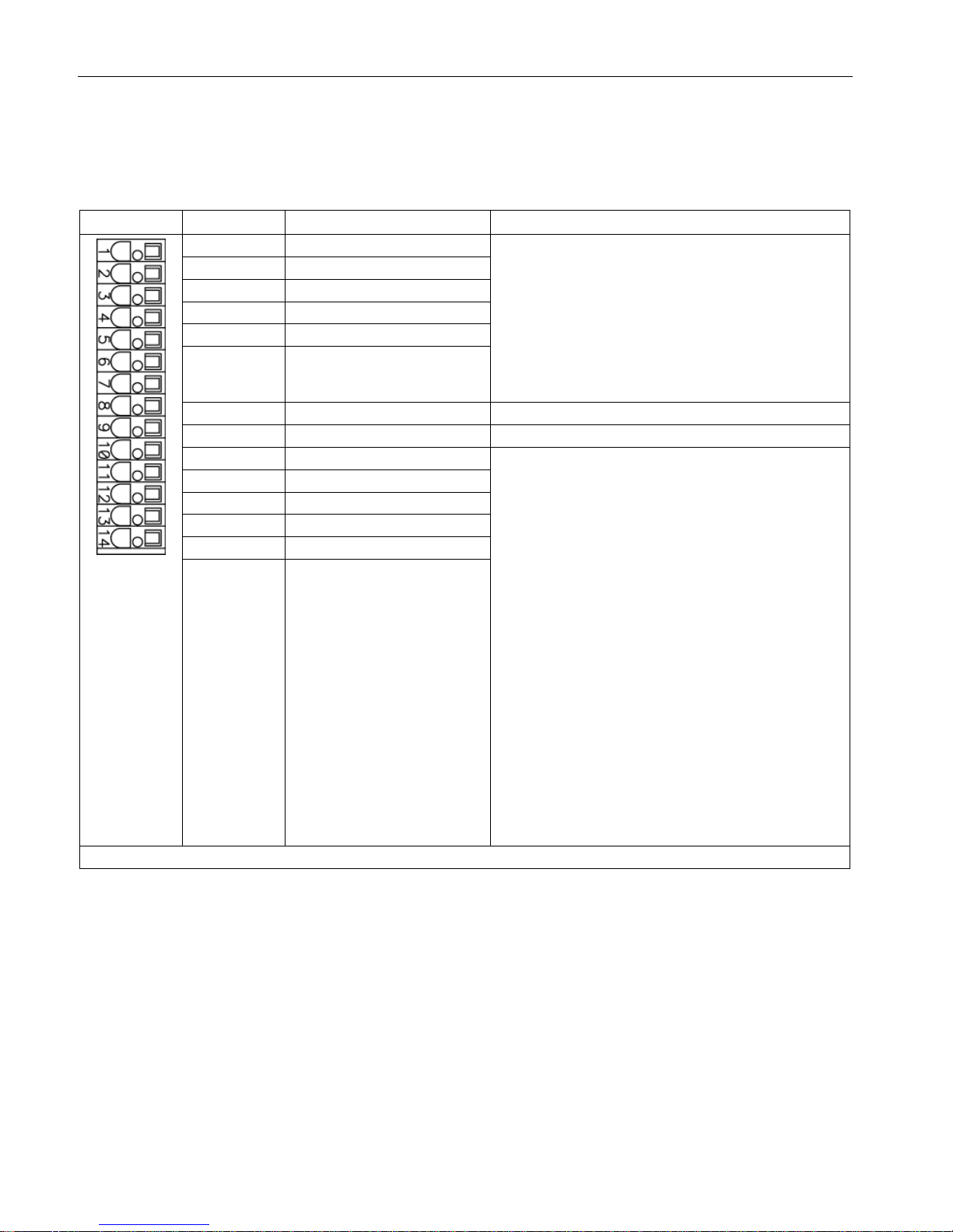
Controlling the safety functions
5.3 Control of "STO" and "SS1" via terminals on the Control Unit and the Motor/Power Module
Safety Integrated
76 Function Manual, 07/2016, A5E03264275A
Terminal strip –X122 on the CU320-2 Control Unit
Table 5- 17 Terminal strip –X122 on the CU320-2 Control Unit
Terminal
Designation 1)
Technical data
1
DI 0
Voltage: -30 ... +30 VDC
Typical power consumption: 9 mA at 24 V
Electrical isolation: Reference potential is terminal M1
Level (incl. ripple)
High level: 15 … 30 V
Low-level: -30 … +5 V
Input delay (typ.):
For "0" → "1": 50 μs
For "1" → "0": 150 μs
2 DI 1
3
DI 2
4
DI 3
5
DI 16
6 DI 17
7
M1
Reference potential for terminals 1 ... 6
8 M Ground
9
DI/DO 8
As input
:
Voltage: -30 ... +30 VDC
Typical power consumption: 9 mA at 24 V
Level (incl. ripple)
High level: 15 … 30 V
Low-level: -30 … +5 V
DI/DO 8, 9, 10, and 11 are "rapid inputs"
2)
Input delay (typ.):
For "0" → "1": 5 μs
For "1" → "0": 50 μs
As output
:
Voltage: 24 V DC
Max. load current per output: 500 mA
Continuous short-circuit proof
Output delay (typ./max.)
3)
:
For "0" → "1": 150 μs / 400 μs
For "1" → "0": 75 μs / 100 μs
Switching frequency:
For resistive load: Max. 100 Hz
For inductive load: Max. 0.5 Hz
For lamp load: Max. 10 Hz
Maximum lamp load: 5 W
10
DI/DO 9
11
M
12
DI/DO 10
13
DI/DO 11
14 M
Max. connectable cross-section: 1.5 mm2
1)
DI: Digital input; DI/DO: Bidirectional digital input/output; M: Electronics ground; M1: Reference ground
2)
The rapid inputs can be used as probe inputs or as inputs for the external zero mark
3)
Data for: Vcc = 24 V; Load 48 Ω; High ("1") = 90% V
out
; Low ("0") = 10% V
out
Page 77

Controlling the safety functions
5.3 Control of "STO" and "SS1" via terminals on the Control Unit and the Motor/Power Module
Safety Integrated
Function Manual, 07/2016, A5E03264275A
77
Note
An open input is interpreted as "low".
To enable the digital inputs (DI) to function, terminal M1 must be connected.
This is achieved by:
1.
Providing the ground reference of the digital inputs, or
2.
A jumper to terminal M.
This removes isolation for these digital inputs.
Note
If the 24
V supply is briefly interrupted, the digital outputs are deactivated for this time.
Page 78
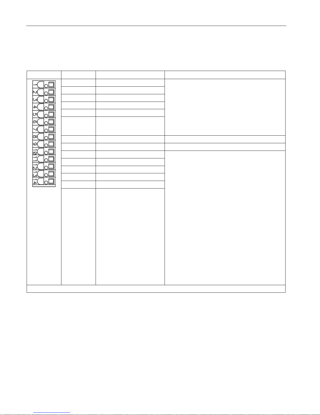
Controlling the safety functions
5.3 Control of "STO" and "SS1" via terminals on the Control Unit and the Motor/Power Module
Safety Integrated
78 Function Manual, 07/2016, A5E03264275A
Terminal strip –X132 on the CU320-2 Control Unit
Table 5- 18 Terminal strip –X132 on the CU320-2 Control Unit
Terminal
Designation 1)
Technical data
1
DI 4
Voltage: -30 ... +30 VDC
Typical power consumption: 9 mA at 24 V
Electrical isolation: Reference potential is terminal M2
Level (incl. ripple)
High level: 15 … 30 V
Low-level: -30 … +5 V
Input delay (typ.):
For "0" → "1": 50 μs
For "1" → "0": 150 μs
2 DI 5
3
DI 6
4
DI 7
5
DI 20
6 DI 21
7
M2
Reference potential for terminals 1 ... 6
8 M Ground
9
DI/DO 12
As input
:
Voltage: -30 ... +30 VDC
Typical power consumption: 9 mA at 24 V
Level (incl. ripple)
High level: 15 … 30 V
Low-level: -30 … +5 V
DI/DO 12, 13, 14, and 15 are "rapid inputs"
2)
Input delay (typ.):
For "0" → "1": 5 μs
For "1" → "0": 50 μs
As output
:
Voltage: 24 V DC
Max. load current per output: 500 mA
Continuous short-circuit proof
Output delay (typ./max.)
3)
:
For "0" → "1": 150 μs / 400 μs
For "1" → "0": 75 μs / 100 μs
Switching frequency:
For resistive load: Max. 100 Hz
For inductive load: Max. 0.5 Hz
For lamp load: Max. 10 Hz
Maximum lamp load: 5 W
10
DI/DO 13
11
M
12
DI/DO 14
13
DI/DO 15
14 M
Max. connectable cross-section: 1.5 mm2
1)
DI: Digital input; DI/DO: Bidirectional digital input/output; M: Electronics ground; M2: Reference ground
2)
The rapid inputs can be used as probe inputs or as inputs for the external zero mark
3)
Data for: Vcc = 24 V; Load 48 Ω; High ("1") = 90% V
out
; Low ("0") = 10% V
out
Page 79

Controlling the safety functions
5.3 Control of "STO" and "SS1" via terminals on the Control Unit and the Motor/Power Module
Safety Integrated
Function Manual, 07/2016, A5E03264275A
79
Note
An open input is interpreted as "low".
To enable the digital inputs (DI) to function, terminal M2 must be connected.
This is achieved by:
1.
Providing the ground reference of the digital inputs, or
2.
A jumper to terminal M.
This removes isolation for these digital inputs.
Note
If the 24
V supply is briefly interrupted, the digital outputs are deactivated for this time.
Wiring
The control cables should be permanently routed (e.g. cable duct, retained using cable ties).
Signal cables and encoder cables should be installed separated from one another.
The shields of the control cables should be grounded through the largest possible surface
area immediately after they enter the control cabinet.
Outside the control cabinet the cables must be routed in such a way that they are safe to
walk on (e.g. as specified in IEC 60204-1).
Page 80

Controlling the safety functions
5.3 Control of "STO" and "SS1" via terminals on the Control Unit and the Motor/Power Module
Safety Integrated
80 Function Manual, 07/2016, A5E03264275A
5.3.7
Control of "STO" and "SS1" for SINAMICS S150
Description
The safety functions contained in the standard ("Safe Torque Off" and "Safe Stop 1") can
also be used without option K82.
Note
Refer to the circuit diagrams enclosed for the interconnections of your device.
Note
The Safety functions must be activated prior to use via parameter assignment. An
acceptance test must be perform
ed and an acceptance log must be created.
The following Safety Integrated Basic Functions (terms according to DIN EN 61800-5-2) can
be activated:
● Safe Torque Off (STO)
● Safe Stop 1 (SS1) (time-controlled)
Note
The integrated safety functions, startin
g from the Safety Integrated (SI) input terminals of the
SINAMICS components (Control Unit, Motor Module), satisfy the requirements of
EN
61800-5-2, EN 60204-1 and DIN EN ISO 13849-1 category 3 (formerly EN 954-1), as
well as the requirements for Performan
ce Level (PL) d and IEC 61508 SIL2.
In addition, most of the SINAMICS safety functions have been certified by independent
institutes. A list of currently certified components is available on request from your local
Siemens office.
Recommended application
This variant is used when:
● Activation will be executed optically isolated with a voltage of 24 VDC.
● Working with control lines that are shorter than 30 m.
● Devices are deployed in plants with low spatial elongation (observe the drop in voltage at
24 VDC!).
Page 81
Controlling the safety functions
5.3 Control of "STO" and "SS1" via terminals on the Control Unit and the Motor/Power Module
Safety Integrated
Function Manual, 07/2016, A5E03264275A
81
Principle of operation
The first shutdown path for the integrated safety functions is activated via a digital input on
the Control Unit. Digital inputs DI 0 to DI 7, DI 16, DI 17, DI 20 and DI 21 are available for
this purpose.
The second shutdown path for the integrated safety functions is activated using the terminals
(-X41:1, -X42:2) on the Control Interface Module of the Motor Module.
The selection and deselection must be simultaneous. The time delay that is unavoidable due
to mechanical switching processes, for example, can be adapted via parameters. p9650
specifies the tolerance time within which the selection/deselection of the two monitoring
channels must occur in order to be considered as "simultaneous".
The selection of the safety function on the Control Unit and on the Control Interface Module
of the Motor Module must be executed over two channels. A switch according to ISO 13850/
EN 418, positive opening according to EC 60947-5-1, or a certified safety controller must be
used as actuating element.
WARNING
Danger to life as a result of failure of the safety functions through unsuitable selection of the
actuating element
An unsuitable actuating element may cause the safety function to fail which can result in
death or serious injury.
• Select the correct actuating element for the purpose of compliance of the overall system
with the required standard (DIN EN ISO 13849-1 (formerly EN954-1) Cat. 3 PL d or DIN
EN 61508 SIL2).
Terminal strip –X41 on the Control Interface Module of the Motor Module
Table 5- 19 Terminal strip –X41 on the Control Interface Module of the Motor Module
Terminal
Function
Technical data
-X41:2
EP +24 V (enable pulses)
Supply voltage: 24 VDC (20.4 ... 28.8 V)
Power consumption: 10 mA
-X41:1
EP M1 (enable pulses)
Page 82
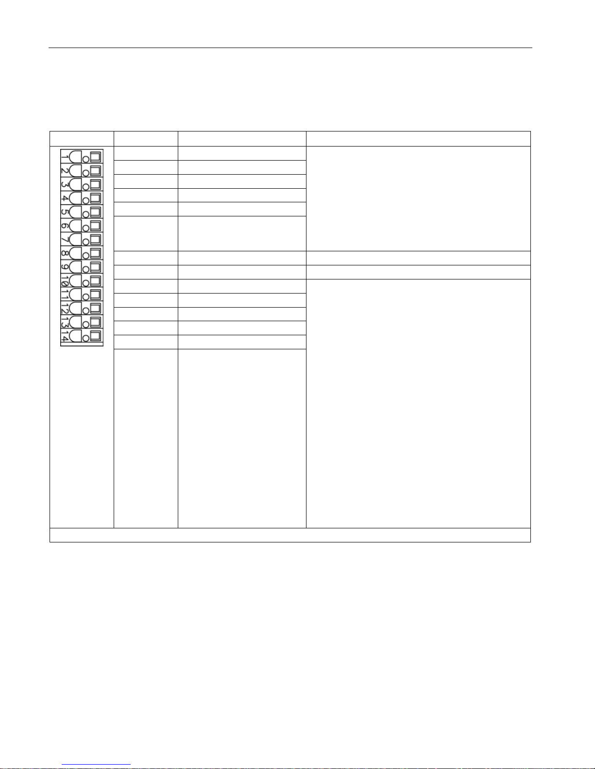
Controlling the safety functions
5.3 Control of "STO" and "SS1" via terminals on the Control Unit and the Motor/Power Module
Safety Integrated
82 Function Manual, 07/2016, A5E03264275A
Terminal strip –X122 on the CU320-2 Control Unit
Table 5- 20 Terminal strip –X122 on the CU320-2 Control Unit
Terminal
Designation 1)
Technical data
1
DI 0
Voltage: -30 ... +30 VDC
Typical power consumption: 9 mA at 24 V
Electrical isolation: Reference potential is terminal M1
Level (incl. ripple)
High level: 15 … 30 V
Low-level: -30 … +5 V
Input delay (typ.):
For "0" → "1": 50 μs
For "1" → "0": 150 μs
2 DI 1
3
DI 2
4
DI 3
5
DI 16
6 DI 17
7
M1
Reference potential for terminals 1 ... 6
8 M Ground
9
DI/DO 8
As input
:
Voltage: -30 ... +30 VDC
Typical power consumption: 9 mA at 24 V
Level (incl. ripple)
High level: 15 … 30 V
Low-level: -30 … +5 V
DI/DO 8, 9, 10, and 11 are "rapid inputs"
2)
Input delay (typ.):
For "0" → "1": 5 μs
For "1" → "0": 50 μs
As output
:
Voltage: 24 V DC
Max. load current per output: 500 mA
Continuous short-circuit proof
Output delay (typ./max.)
3)
:
For "0" → "1": 150 μs / 400 μs
For "1" → "0": 75 μs / 100 μs
Switching frequency:
For resistive load: Max. 100 Hz
For inductive load: Max. 0.5 Hz
For lamp load: Max. 10 Hz
Maximum lamp load: 5 W
10
DI/DO 9
11
M
12
DI/DO 10
13
DI/DO 11
14 M
Max. connectable cross-section: 1.5 mm2
1)
DI: Digital input; DI/DO: Bidirectional digital input/output; M: Electronics ground; M1: Reference ground
2)
The rapid inputs can be used as probe inputs or as inputs for the external zero mark
3)
Data for: Vcc = 24 V; Load 48 Ω; High ("1") = 90% V
out
; Low ("0") = 10% V
out
Page 83

Controlling the safety functions
5.3 Control of "STO" and "SS1" via terminals on the Control Unit and the Motor/Power Module
Safety Integrated
Function Manual, 07/2016, A5E03264275A
83
Note
An open input is interpreted as "low".
To enable the digital inputs (DI) to function, terminal M1 must be connected.
This is achieved by:
1.
Providing the ground reference of the digital inputs, or
2.
A jumper to terminal M.
This removes isolation for these digital inputs.
Note
If the 24
V supply is briefly interrupted, the digital outputs are deactivated for this time.
Page 84
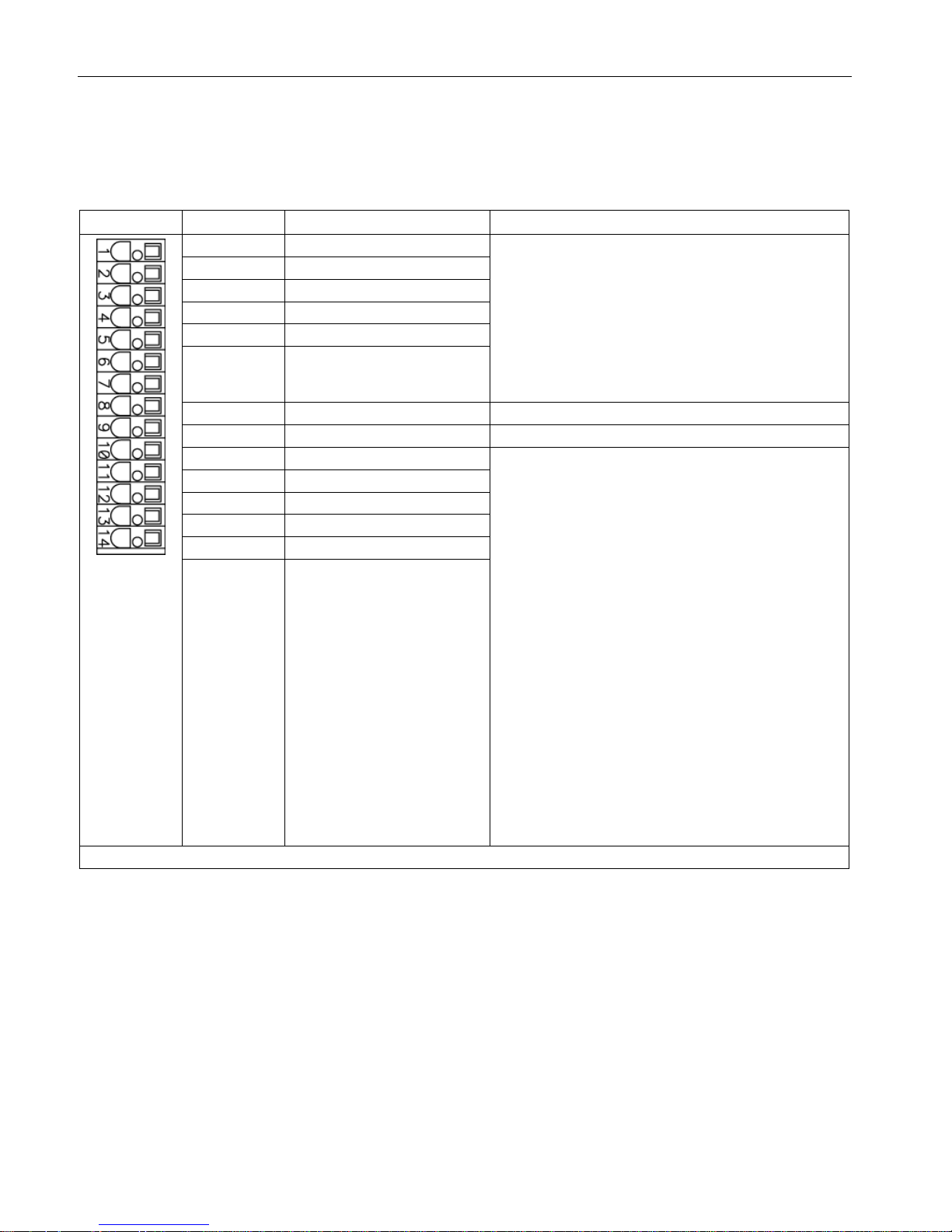
Controlling the safety functions
5.3 Control of "STO" and "SS1" via terminals on the Control Unit and the Motor/Power Module
Safety Integrated
84 Function Manual, 07/2016, A5E03264275A
Terminal strip –X132 on the CU320-2 Control Unit
Table 5- 21 Terminal strip –X132 on the CU320-2 Control Unit
Terminal
Designation 1)
Technical data
1
DI 4
Voltage: -30 ... +30 VDC
Typical power consumption: 9 mA at 24 V
Electrical isolation: Reference potential is terminal M2
Level (incl. ripple)
High level: 15 … 30 V
Low-level: -30 … +5 V
Input delay (typ.):
For "0" → "1": 50 μs
For "1" → "0": 150 μs
2 DI 5
3
DI 6
4
DI 7
5
DI 20
6 DI 21
7
M2
Reference potential for terminals 1 ... 6
8 M Ground
9
DI/DO 12
As input
:
Voltage: -30 ... +30 VDC
Typical power consumption: 9 mA at 24 V
Level (incl. ripple)
High level: 15 … 30 V
Low-level: -30 … +5 V
DI/DO 12, 13, 14, and 15 are "rapid inputs"
2)
Input delay (typ.):
For "0" → "1": 5 μs
For "1" → "0": 50 μs
As output
:
Voltage: 24 V DC
Max. load current per output: 500 mA
Continuous short-circuit proof
Output delay (typ./max.)
3)
:
For "0" → "1": 150 μs / 400 μs
For "1" → "0": 75 μs / 100 μs
Switching frequency:
For resistive load: Max. 100 Hz
For inductive load: Max. 0.5 Hz
For lamp load: Max. 10 Hz
Maximum lamp load: 5 W
10
DI/DO 13
11
M
12
DI/DO 14
13
DI/DO 15
14 M
Max. connectable cross-section: 1.5 mm2
1)
DI: Digital input; DI/DO: Bidirectional digital input/output; M: Electronics ground; M2: Reference ground
2)
The rapid inputs can be used as probe inputs or as inputs for the external zero mark
3)
Data for: Vcc = 24 V; Load 48 Ω; High ("1") = 90% V
out
; Low ("0") = 10% V
out
Page 85

Controlling the safety functions
5.3 Control of "STO" and "SS1" via terminals on the Control Unit and the Motor/Power Module
Safety Integrated
Function Manual, 07/2016, A5E03264275A
85
Note
An open input is interpreted as "low".
To enable the digital inputs (DI) to function, terminal M2 must be connected.
This is achieved by:
1.
Providing the ground reference of the digital inputs, or
2.
A jumper to terminal M.
This removes isolation for these digital inputs.
Note
If the 24
V supply is briefly interrupted, the digital outputs are deactivated for this time.
Wiring
The control cables should be permanently routed (e.g. cable duct, retained using cable ties).
Signal cables and encoder cables should be installed separated from one another.
The shields of the control cables should be grounded through the largest possible surface
area immediately after they enter the control cabinet.
Outside the control cabinet, the cables must be routed in such a way that they are safe to
walk on (e.g. as specified in IEC 60204-1).
Page 86

Controlling the safety functions
5.4 Activating "SBC" via the Safe Brake Adapter
Safety Integrated
86 Function Manual, 07/2016, A5E03264275A
5.4
Activating "SBC" via the Safe Brake Adapter
5.4.1
Activating "SBC" via the Safe Brake Adapter for option K88 (230 V AC)
Description
The Safe Brake Control (SBC) is a safety function which is used in safety-related
applications, e.g. in presses or in rolling mills. In the no-current state, the brake acts on the
motor of the drive using spring force. The brake is released when current flows (=low active).
The Safe Brake Adapter 230 VAC is installed in the factory in the cabinet unit. Power is
connected to terminal -X12 on the Safe Brake Adapter. A connection between the Safe
Brake Adapter and the Control Interface Module is established in the factory so that the Safe
Brake Adapter can be controlled.
For controlling the brake, a connection must be established on site between terminal -X14 on
the Safe Brake Adapter and the rectifier of the brake. Direct connection of AC brakes is not
permissible.
Fast de-energization
Some brake rectifier types feature two additional connections for switching the brake load on
the DC side. This allows the brake coil to be quickly de-energized, i.e. the braking effect
starts earlier.
The Safe Brake Adapter supports such a fast de-energization using the two additional
connections -X15:1 and -X15:2. This function is not part of the safe brake control.
Note
Determination of the time until the brake engages without fast de-energization
As the fast de
-energization is not part of the safety function, this functionality is not
monitored. The fast de
-energization can therefore fail during operation without being noticed.
Therefore, to determine the time until the brake engages for a machine acceptance, the fast
d
e-energization must be bypassed by short-circuiting the terminals at X15:1, 2.
Page 87
Controlling the safety functions
5.4 Activating "SBC" via the Safe Brake Adapter
Safety Integrated
Function Manual, 07/2016, A5E03264275A
87
Safety instructions
Note
The integrated safety functions, starting from the Safety Integrated (SI) input terminals of the
SINAMICS components (Control Unit, Motor Module),
satisfy the requirements of EN 61800-
5
-2, EN 60204-1 and DIN EN ISO 13849-1 category 3 (formerly EN 954-1), as well as the
requirements for Performance Level (PL) d and IEC 61508 SIL2.
With the Safe Brake Adapter (option K89), the requirements specified i
n EN 61800-5-2, EN
60204
-1, DIN EN ISO 13849-1 Category 3 (formerly EN954-1) as well as for Performance
Level (PL) d and IEC 61508 SIL 2 are fulfilled.
NOTICE
Equipment fault caused by connection of a 24 VDC brake
If a 24 VDC brake is connected to option K88, Safe Brake Adapter 230 VAC on the system
side, then this can cause damage to the Safe Brake Adapter.
This can result in the following undesirable effects:
1. Closing the brake is not displayed on the LEDS.
2. The fuse is ruptured.
3. The contact service life of the relay is reduced.
• Do not connect a 24 VDC brake to the 230 VAC Safe Brake Adapter.
Page 88
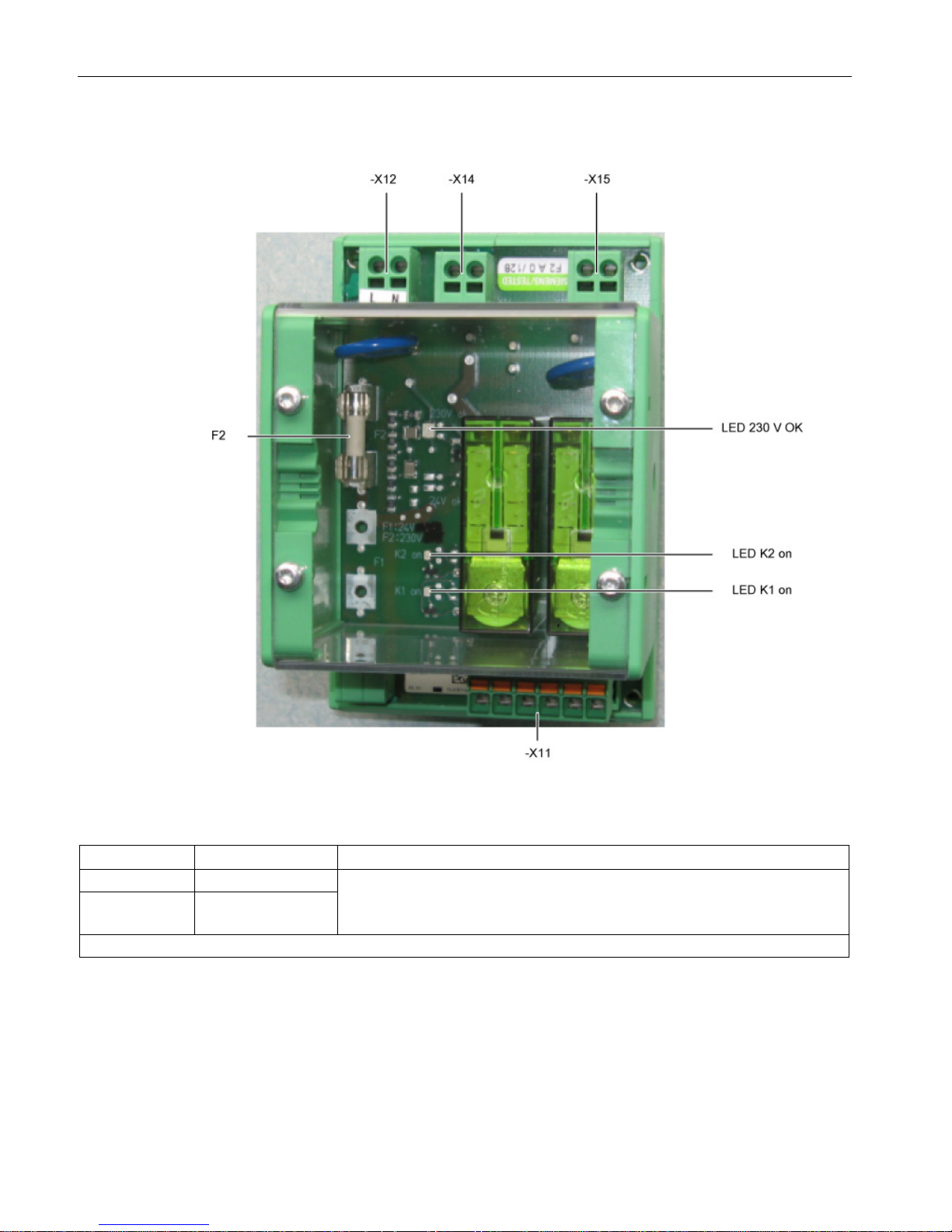
Controlling the safety functions
5.4 Activating "SBC" via the Safe Brake Adapter
Safety Integrated
88 Function Manual, 07/2016, A5E03264275A
Interfaces
Figure 5-7 Safe Brake Adapter interface overview 230 VAC
Table 5- 22 Terminal strip X12, 230 VAC power supply
Connection
Signal
Description
X12.1
L
Supply voltage: 230 VAC
Current consumption: 2 A
Protection according to IEC 60269-1, operating class gG
X12.2 N
Max. connectable cross-section 2.5 mm2
Page 89
Controlling the safety functions
5.4 Activating "SBC" via the Safe Brake Adapter
Safety Integrated
Function Manual, 07/2016, A5E03264275A
89
Table 5- 23 Terminal block X14, interface to the load
Connection
Signal
Description
X14.1
BR L
Supply voltage: 230 VAC
Current consumption: 2 A, only for brakes with brake rectifier
X14.2 BR N
Max. connectable cross-section 2.5 mm2
WARNING
Danger to life if the permissible cable length of the brake control is exceeded
If the permissible cable length of the brake control is exceeded this can result in death or
serious injury in the event of an error.
• The maximum permissible cable length of 300 m between the 230 VAC Safe Brake
Adapter and the brake must be carefully maintained.
• To accurately calculate the maximum cable length, see the SINAMICS Low Voltage
Configuration Manual on the customer DVD supplied with the device.
Table 5- 24 Terminal block X15, fast de-energization
Connection
Signal
Description
X15.1
AUX1
Supply voltage: 230 VAC
Current consumption: 2 A
X15.2
AUX2
Max. connectable cross-section 2.5 mm2
Spare fuse
The type of spare fuse is as follows: 2 A, time-lag.
Note
Correctly mounting the housing cover after replacing a fuse
An adhesive label is provided on the housing cover indicating the position of the connector.
Mou
nt the cover in the correct position so that the inscription of the label matches the actual
connectors.
Page 90

Controlling the safety functions
5.4 Activating "SBC" via the Safe Brake Adapter
Safety Integrated
90 Function Manual, 07/2016, A5E03264275A
5.4.2
Safe Brake Adapter SBA 230 V AC for SINAMICS G130/SINAMICS S120
Chassis
Description
The Safe Brake Control (SBC) is a safety function which is used in safety-related
applications, e.g. in presses or in rolling mills. In the no-current state, the brake acts on the
motor of the drive using spring force. The brake is released when current flows (=low active).
Power must be connected to terminal -X12 on the Safe Brake Adapter.
For controlling the brake, a connection must be established between terminal -X14 on the
Safe Brake Adapter and the rectifier of the brake.
For the control, a connection must be established between the Safe Brake Adapter and the
Control Interface Module.
The cable harness with article number 6SL3060-4DX04-0AA0 can be used.
Fast de-energization
Some brake rectifier types feature two additional connections for switching the brake load on
the DC side. This allows the brake coil to be quickly de-energized, i.e. the braking effect
starts earlier.
The Safe Brake Adapter supports such fast de-energizing using the two additional
connections -X15:1 and -X15:2. This function does not belong to safe brake control.
Note
Determination of the time until the brake engages without fast de-energization
As the fast de
-energization is not part of the safety function, this functionality is not
monitored. The fast de
-energization can therefore fail during operation without being noticed.
Therefore, to determine the time until the brake engages for a machine acceptance, the fast
de
-energization must be bypassed by short-circuiting the terminals at X15:1, 2.
Page 91
Controlling the safety functions
5.4 Activating "SBC" via the Safe Brake Adapter
Safety Integrated
Function Manual, 07/2016, A5E03264275A
91
Safety instructions
Note
The integrated safety functions, starting from the Safety Integrated (SI) input terminals of the
SINAMICS components (Control Unit, Motor Module), satisfy the requirements of EN
61800-
5
-2, EN 60204-1 and DIN EN ISO 13849-1 category 3 (formerly EN 954-1), as well as the
requirements for Performance Level (PL) d and IEC 61508 SIL2.
With the Safe Brake Adapter, the requirements specified in EN
61800-5-2, EN 60204-1, as
well as in DIN EN ISO 13849
-1 Category 3 (formerly EN954-1) are satisfied for Performance
Level (PL) d and IEC 61508 SIL 2.
NOTICE
Equipment fault caused by connection of a 24 VDC brake
If a 24 VDC brake is connected to option K88, Safe Brake Adapter 230 VAC on the system
side, then this can cause damage to the Safe Brake Adapter.
This can result in the following undesirable effects:
1. Closing the brake is not displayed on the LEDS.
2. The fuse is ruptured.
3. The contact service life of the relay is reduced.
• Do not connect a 24 VDC brake to the 230 VAC Safe Brake Adapter.
Page 92
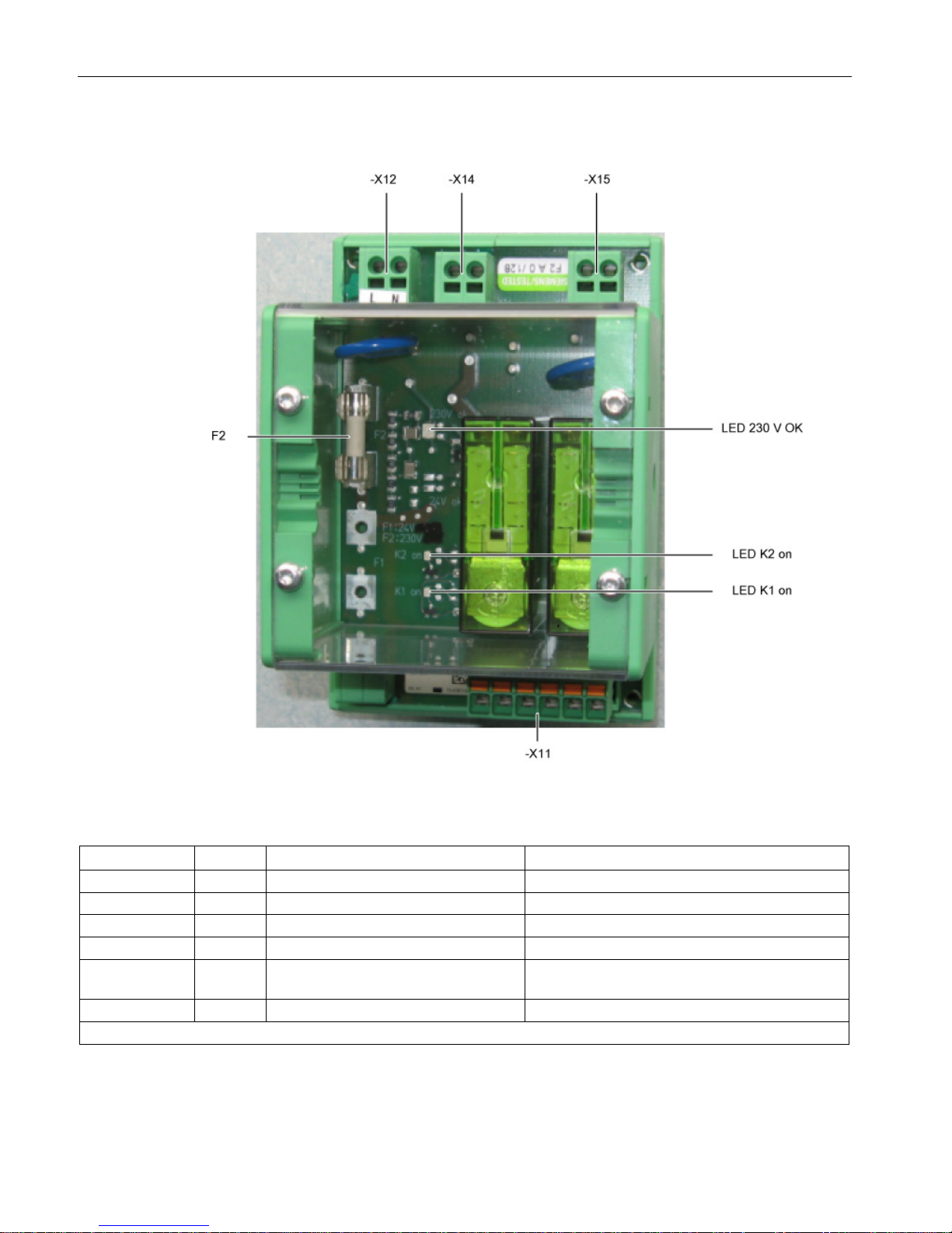
Controlling the safety functions
5.4 Activating "SBC" via the Safe Brake Adapter
Safety Integrated
92 Function Manual, 07/2016, A5E03264275A
Interfaces
Figure 5-8 Safe Brake Adapter interface overview 230 VAC
Table 5- 25 Terminal block X11, interface to the Control Interface Module
Connection
Signal
Description
Technical data
X11.1
BR+
Control channel 1
Connection to the Control Interface Module, X46:1
X11.2
BR-
Control channel 2
Connection to the Control Interface Module, X46:2
X11.3
FB+
Relay feedback signal
Connection to the Control Interface Module, X46:3
X11.4
FB-
Ground of the relay feedback signal
Connection to the Control Interface Module, X46:4
X11.5 P24 P24 of the auxiliary voltage to supply
the feedback signal
Connection to the Control Interface Module, X42:2
X11.6
M
Ground of the auxiliary voltage
Connection to the Control Interface Module, X42:3
Max. connectable cross-section 2.5 mm2
Page 93
Controlling the safety functions
5.4 Activating "SBC" via the Safe Brake Adapter
Safety Integrated
Function Manual, 07/2016, A5E03264275A
93
WARNING
Danger to life if the maximum permissible cable length between the Safe Brake Adapter
and the Control Interface Module is exceeded
If the permissible cable length between the Safe Brake Adapter and the Control Interface
Module is exceeded this can result in death or serious injury in the event of an error.
• The maximum permissible cable length of 10 m between the 230 VAC Safe Brake
Adapter and the brake must be carefully maintained.
• The cable must be routed according to ISO 13849-2, Table D.4.
• It is recommended that the cable harness (length 4 m) with article number
6SL3060-4DX04-0AA0 is used.
Table 5- 26 Terminal strip X12, 230 VAC power supply
Connection
Signal
Description
X12.1
L
Supply voltage: 230 VAC
Current consumption: 2 A
Protection according to IEC 60269-1, operating class gG
X12.2 N
Max. connectable cross-section 2.5 mm2
Table 5- 27 Terminal block X14, interface to the load
Connection
Signal
Description
X14.1
BR L
Supply voltage: 230 VAC
Current consumption: 2 A, only for brakes with brake rectifier
X14.2
BR N
Max. connectable cross-section 2.5 mm2
WARNING
Danger to life if the permissible cable length of the brake control is exceeded
If the permissible cable length of the brake control is exceeded this can result in death or
serious injury in the event of an error.
• The maximum permissible cable length of 300 m between the 230 VAC Safe Brake
Adapter and the brake must be carefully maintained.
• To accurately calculate the maximum cable length, see the SINAMICS Low Voltage
Configuration Manual on the customer DVD supplied with the device.
Page 94
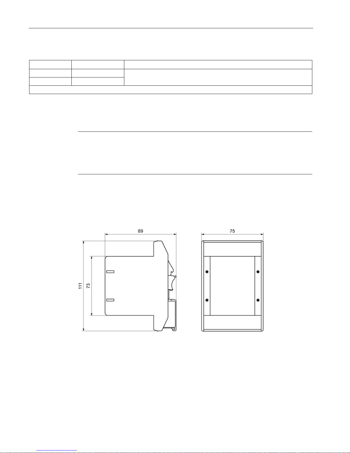
Controlling the safety functions
5.4 Activating "SBC" via the Safe Brake Adapter
Safety Integrated
94 Function Manual, 07/2016, A5E03264275A
Table 5- 28 Terminal block X15, fast de-energization
Connection
Signal
Description
X15.1
AUX1
Supply voltage: 230 VAC
Current consumption: 2 A
X15.2 AUX2
Max. connectable cross-section 2.5 mm2
Spare fuse
The type of spare fuse is as follows: 2 A, time-lag.
Note
Correctly mounting the housing cover after replacing a fuse
An adhesive label is provided on the housing cover indicating the position of the connector.
Mount the cover in the correct position so that the inscription of the label matches the actual
connectors
.
Mounting
The Safe Brake Adapter is designed for mounting on a rail according to EN 60715
The dimensions are shown in the following dimension drawing.
Figure 5-9 Dimension drawing of the Safe Brake Adapter (data in mm)
Page 95
Controlling the safety functions
5.5 Control by way of PROFIsafe
Safety Integrated
Function Manual, 07/2016, A5E03264275A
95
Technical data
Table 5- 29 Technical data
6SL3355-2DX00-1AA0
Electronic power supply
Power supply voltage (via the Control Interface Module)
24 VDC (20.4 ... 28.8)
Power supply of the motor holding brake
230 VAC
Max. permissible current drain of the motor holding brake
2 A
Max. permissible current drain of the fast de-energization
2 A
Weight
0.250 kg
5.5
Control by way of PROFIsafe
The activation via PROFIsafe is described in detail in the SINAMICS S120 Safety Integrated
Function Manual.
The "SINAMICS S120 Safety Integrated Function Manual" is available on the Internet at the
following address (https://support.industry.siemens.com/cs/ww/en/ps/13231/man).
Page 96
Controlling the safety functions
5.6 Control via TM54F
Safety Integrated
96 Function Manual, 07/2016, A5E03264275A
5.6
Control via TM54F
The activation via TM54F is described in detail in the SINAMICS S120 Safety Integrated
Function Manual.
The "SINAMICS S120 Safety Integrated Function Manual" is available on the Internet at the
following address (https://support.industry.siemens.com/cs/ww/en/ps/13231/man).
5.6.1
Control via TM54F for SINAMICS G130, S120 Chassis
The TM54F Terminal Module must be supplied with 24 VDC and connected to the Control
Unit via DRIVE-CLiQ.
WARNING
Fire hazard due to overheating because of inadequate ventilation clearances
Insufficient ventilation clearances result in overheating with danger to persons as a result of
smoke and fire. This can also result in more downtimes and reduced service lives of the
Terminal Module.
• For this reason, it is imperative that you maintain the 50 mm clearances above and
below the Terminal Module.
5.6.2
Control via option K87 for SINAMICS S120 Cabinet Modules
With option K87 the Terminal Module TM54F is integrated in the cabinet unit (-A70) and
connected with the Control Unit via DRIVE-CLiQ.
5.6.3
Control via K87 for SINAMICS S150
With option K87 the Terminal Module TM54F is integrated in the cabinet unit (-A70) and
connected with the Control Unit via DRIVE-CLiQ.
Page 97
Controlling the safety functions
5.7 Motion monitoring without selection
Safety Integrated
Function Manual, 07/2016, A5E03264275A
97
5.7
Motion monitoring without selection
As an alternative to controlling via terminals and/or PROFIsafe, there is also the option to
parameterize several safety functions without selection. For this mode, after
parameterization and a POWER ON, these functions are permanently selected.
Example
"SLS without selection" can be used, for example, to monitor the maximum velocity to
prevent that the drive exceeds a mechanical speed limit. For this purpose, using the "without
selection" function, an F-DI does not have to be used; an F-CPU is also not required.
Features
● The function "Motion monitoring without selection" is available in the following versions:
p9601
Meaning
Functionality
Comment
0024
hex
Drive-integrated motion monitoring
functions without selection are
enabled
• SLS
• SDI
• p9501.0 = 1
• p9501.17 = 1
0025
hex
Drive-integrated motion monitoring
functions without selection with
STO via terminals are enabled
• SLS
• SDI
• STO
• SS1
• SBC
• p9501.0 = 1
• p9501.17 = 1
• Basic Functions
• Basic Functions
• Basic Functions
● The functions "SLS without selection" and "SDI without selection positive/negative" are
selected with p9512.
● The functions without selection are available in the versions "with encoder" and "without
encoder" (selection via p9506).
● The functions without selection are parameterized and enabled in the same way as the
versions with control via PROFIsafe/terminals.
Acknowledging safety faults
For acknowledging safety faults, a distinction should be made between the following cases:
● Drive-integrated motion monitoring functions without selection
Acknowledging safety faults is only possible with POWER ON.
● Drive-integrated motion monitoring functions without selection and Basic Functions via
onboard terminals
Acknowledging Safety faults is possible with POWER ON or selecting/deselecting STO or
SS1.
Page 98

Controlling the safety functions
5.7 Motion monitoring without selection
Safety Integrated
98 Function Manual, 07/2016, A5E03264275A
Differences
Differences in the behavior of the functions to the versions with control via
PROFIsafe/terminals are described in the sections for commissioning the individual
functions.
Overview of important parameters
•
p9501.0
SI Motion enable safety functions (Control Unit)
•
p9512
SI Motion enable safety functions without selection (Control Unit)
•
p9601
SI enable functions integrated in the drive (Control Unit)
Page 99

Safety Integrated
Function Manual, 07/2016, A5E03264275A
99
6
The commissioning of the Safety Integrated functions and the acceptance test are described
in detail in the SINAMICS S120 Safety Integrated Function Manual.
The "SINAMICS S120 Safety Integrated Function Manual" is available on the Internet at the
following address (https://support.industry.siemens.com/cs/ww/en/ps/13231/man).
Page 100

Commissioning and acceptance test
Safety Integrated
100 Function Manual, 07/2016, A5E03264275A
 Loading...