

Page 1

SINAMICS G: Control of a G120 or G110M with an Allen-Bradley controller (Compact/ ControlLogix) via EtherNet/IP
SINAMICS G120, G110M
https://support.industry.siemens.com/cs/ww/en/view/82843076
Siemens
Industry
Online
Support
Page 2

Legal information
SINAMICS G: Control of a G120 with an Allen-Bradley controller
(Compact/ ControlLogix with RSLogix 5000) via EtherNet/IP
Entry-ID: 82843076, V4.0, 09/2018
2
Siemens AG
2015 All rights reserved
Legal information
Use of application examples
Application examples illustrate the solution of automation tasks through an interaction of several
components in the form of text, graphics and/or software modules. The application examples are
a free service by Siemens AG and/or a subsidiary of Siemens AG (“Siemens”). They are nonbinding and make no claim to completeness or functionality regarding configuration and
equipment. The application examples merely offer help with typical tasks; they do not constitute
customer-specific solutions. You yourself are responsible for the proper and safe operation of the
products in accordance with applicable regulations and must also check the function of the
respective application example and customize it for your system.
Siemens grants you the non-exclusive, non-sublicensable and non-transferable right to have the
application examples used by technically trained personnel. Any change to the application
examples is your responsibility. Sharing the application examples with third parties or copying the
application examples or excerpts thereof is permitted only in combination with your own products.
The application examples are not required to undergo the customary tests and quality inspections
of a chargeable product; they may have functional and performance defects as well as errors. It is
your responsibility to use them in such a manner that any malfunctions that may occur do not
result in property damage or injury to persons.
Disclaimer of liability
Siemens shall not assume any liability, for any legal reason whatsoever, including, without
limitation, liability for the usability, availability, completeness and freedom from defects of the
application examples as well as for related information, configuration and performance data and
any damage caused thereby. This shall not apply in cases of mandatory liability, for example
under the German Product Liability Act, or in cases of intent, gross negligence, or culpable loss of
life, bodily injury or damage to health, non-compliance with a guarantee, fraudulent
non-disclosure of a defect, or culpable breach of material contractual obligations. Claims for
damages arising from a breach of material contractual obligations shall however be limited to the
foreseeable damage typical of the type of agreement, unless liability arises from intent or gross
negligence or is based on loss of life, bodily injury or damage to health. The foregoing provisions
do not imply any change in the burden of proof to your detriment. You shall indemnify Siemens
against existing or future claims of third parties in this connection except where Siemens is
mandatorily liable.
By using the application examples you acknowledge that Siemens cannot be held liable for any
damage beyond the liability provisions described.
Other information
Siemens reserves the right to make changes to the application examples at any time without
notice. In case of discrepancies between the suggestions in the application examples and other
Siemens publications such as catalogs, the content of the other documentation shall have
precedence.
The Siemens terms of use (https://support.industry.siemens.com) shall also apply.
Security information
Siemens provides products and solutions with industrial security functions that support the secure
operation of plants, systems, machines and networks.
In order to protect plants, systems, machines and networks against cyber threats, it is necessary
to implement – and continuously maintain – a holistic, state-of-the-art industrial security concept.
Siemens’ products and solutions constitute one element of such a concept.
Customers are responsible for preventing unauthorized access to their plants, systems, machines
and networks. Such systems, machines and components should only be connected to an
enterprise network or the Internet if and to the extent such a connection is necessary and only
when appropriate security measures (e.g. firewalls and/or network segmentation) are in place.
For additional information on industrial security measures that may be implemented, please visit
https://www.siemens.com/industrialsecurity.
Siemens’ products and solutions undergo continuous development to make them more secure.
Siemens strongly recommends that product updates are applied as soon as they are available
and that the latest product versions are used. Use of product versions that are no longer
supported, and failure to apply the latest updates may increase customer’s exposure to cyber
threats.
To stay informed about product updates, subscribe to the Siemens Industrial Security RSS Feed
at: https://www.siemens.com/industrialsecurity.
Page 3

Table of contents
SINAMICS G: Control of a G120 with an Allen-Bradley controller
(Compact/ ControlLogix with RSLogix 5000) via EtherNet/IP
Entry-ID: 82843076, V4.0, 09/2018
3
Siemens AG
2015 All rights reserved
Table of contents
Legal information ......................................................................................................... 2
1 Introduction ........................................................................................................ 5
1.1 EtherNet/IP Overview ........................................................................... 5
1.2 SINAMICS G series Connectivity to EtherNet/IP ................................. 5
2 Solution Overview ............................................................................................. 6
2.1 Solution Overview ................................................................................ 6
2.2 Used Components ................................................................................ 6
3 Programming Overview .................................................................................... 7
3.1 Configuration Choices .......................................................................... 7
3.2 AOI’s for SINAMICS G Series drives ................................................... 8
3.3 AOI Types ............................................................................................ 8
4 SINAMICS G120 Add-On Instructions ............................................................. 9
4.1 Function Description ............................................................................. 9
4.2 Telegram Descriptions ......................................................................... 9
4.2.1 Telegram Type 1 for Simple Speed ...................................................... 9
4.2.2 Telegram Type 352 for Simple Speed .................................................. 9
4.2.3 Telegram Type 111 for EPOS mode .................................................. 10
4.3 Basic Speed Control –Telegram 1 ..................................................... 11
4.3.1 Functionality ....................................................................................... 11
4.3.2 Schematic Ladder Representation ..................................................... 11
4.3.3 Input and Output Parameters ............................................................. 11
4.4 Speed Control –Telegram 352 ........................................................... 12
4.4.1 Functionality ....................................................................................... 12
4.4.2 Schematic Ladder Representation ..................................................... 13
4.4.3 Input and Output parameters ............................................................. 13
4.5 EPOS Control ..................................................................................... 15
4.5.1 Functionality ....................................................................................... 15
4.5.2 Schematic Ladder Representation ..................................................... 15
4.5.3 Input and Output parameters ............................................................. 16
4.6 UDTs .................................................................................................. 18
5 Drive Configuration ......................................................................................... 19
5.1 Configuring IP Address of CU ............................................................ 19
5.2 Using a Freely Configurable Telegram ............................................... 23
5.2.1 Example of "Free telegram" commissioning ...................................... 24
6 Configuring a Generic Ethernet Module........................................................ 25
6.1 Adding a new module in RSLogix ...................................................... 25
6.1.1 Inserting the module in an RSLogix project ....................................... 25
6.1.2 Configuring network parameters ........................................................ 26
6.1.3 Connection Parameters...................................................................... 27
6.1.4 Using IO Data ..................................................................................... 27
7 Using AIOs in a new application .................................................................... 28
7.1 Importing AIOs ................................................................................... 28
7.1.1 Installing L5K Files in RSLogix ........................................................... 28
7.2 Using the AOI ..................................................................................... 29
7.2.1 Adding AOI to an RSLogix Program .................................................. 29
7.2.2 I/O Interface ........................................................................................ 30
8 Drive Parameter Access.................................................................................. 31
8.1 Explicit Messaging .............................................................................. 31
Page 4

Table of contents
SINAMICS G: Control of a G120 with an Allen-Bradley controller
(Compact/ ControlLogix with RSLogix 5000) via EtherNet/IP
Entry-ID: 82843076, V4.0, 09/2018
4
Siemens AG
2015 All rights reserved
8.2 Using the MSG Instruction ................................................................. 32
9 Troubleshooting .............................................................................................. 37
9.1 I can’t go online with the drive in Starter using the Ethernet
cable. .................................................................................................. 37
9.2 The drive and the PLC are not communicating .................................. 37
10 Glossary ........................................................................................................... 40
11 Appendix .......................................................................................................... 41
11.1 Service and support ........................................................................... 41
11.2 Change documentation ...................................................................... 42
Page 5
1 Introduction
SINAMICS G: Control of a G120 with an Allen-Bradley controller
(Compact/ ControlLogix with RSLogix 5000) via EtherNet/IP
Entry-ID: 82843076, V4.0, 09/2018
5
Siemens AG
2015 All rights reserved
1 Introduction
1.1 EtherNet/IP Overview
Industrial Ethernet communication networks continue to gain global importance in
automation solutions. Industrial Ethernet connectivity down to device level
components (i.e. drives, I/O, etc.) is an end user requirement that demands
openness and flexibility. To capitalize on the flexibility to connect to different
Industrial Ethernet protocols the SINAMICS G120 can seamlessly be applied in
PROFINET and EtherNet/IP networks.
1.2 SINAMICS G series Connectivity to EtherNet/IP
The SINAMICS drive family offers both PROFINET and EtherNet/IP software
stacks for the SINAMICS G series which is easily selected via a parameter setting
in the standard SINAMICS firmware.
The network IP address of the SINAMICS G drive can be set through the
STARTER software. With STARTER software installed on your computer you can
connect to the SINAMICS drive through PROFINET or EtherNet/IP.
The SINAMICS drives operate on unicast telegrams which reduces network traffic.
SINAMICS G drives have been certified by ODVA for EtherNet/IP conformance
testing and participated in the EtherNet/IP PlugFest. Siemens is a member of
ODVA with Vendor ID # 1251.
Figure 1-1
Page 6
2 Solution Overview
SINAMICS G: Control of a G120 with an Allen-Bradley controller
(Compact/ ControlLogix with RSLogix 5000) via EtherNet/IP
Entry-ID: 82843076, V4.0, 09/2018
6
Siemens AG
2015 All rights reserved
2 Solution Overview
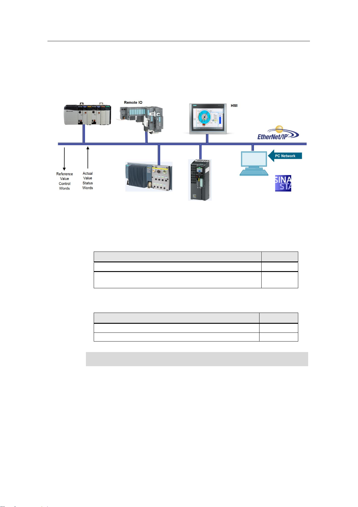
2.1 Solution Overview
Figure 2-1
2.2 Used Components
The application was generated with the following components:
Hardware Components
Component
No.
PROFINET versions of G120 with Firmware version 4.10.1
1
Rockwell Automation Logix family controller Firmware version
20
1
Software components
Component
No.
STARTER Version 5.1.1 or later
1
RS Logix 5000 Version 20 or later
1
NOTE
RSLogix 5000 Version 19 can be used when not using the EDS file
Page 7
3 Programming Overview
SINAMICS G: Control of a G120 with an Allen-Bradley controller
(Compact/ ControlLogix with RSLogix 5000) via EtherNet/IP
Entry-ID: 82843076, V4.0, 09/2018
7
Siemens AG
2015 All rights reserved
3 Programming Overview
3.1 Configuration Choices
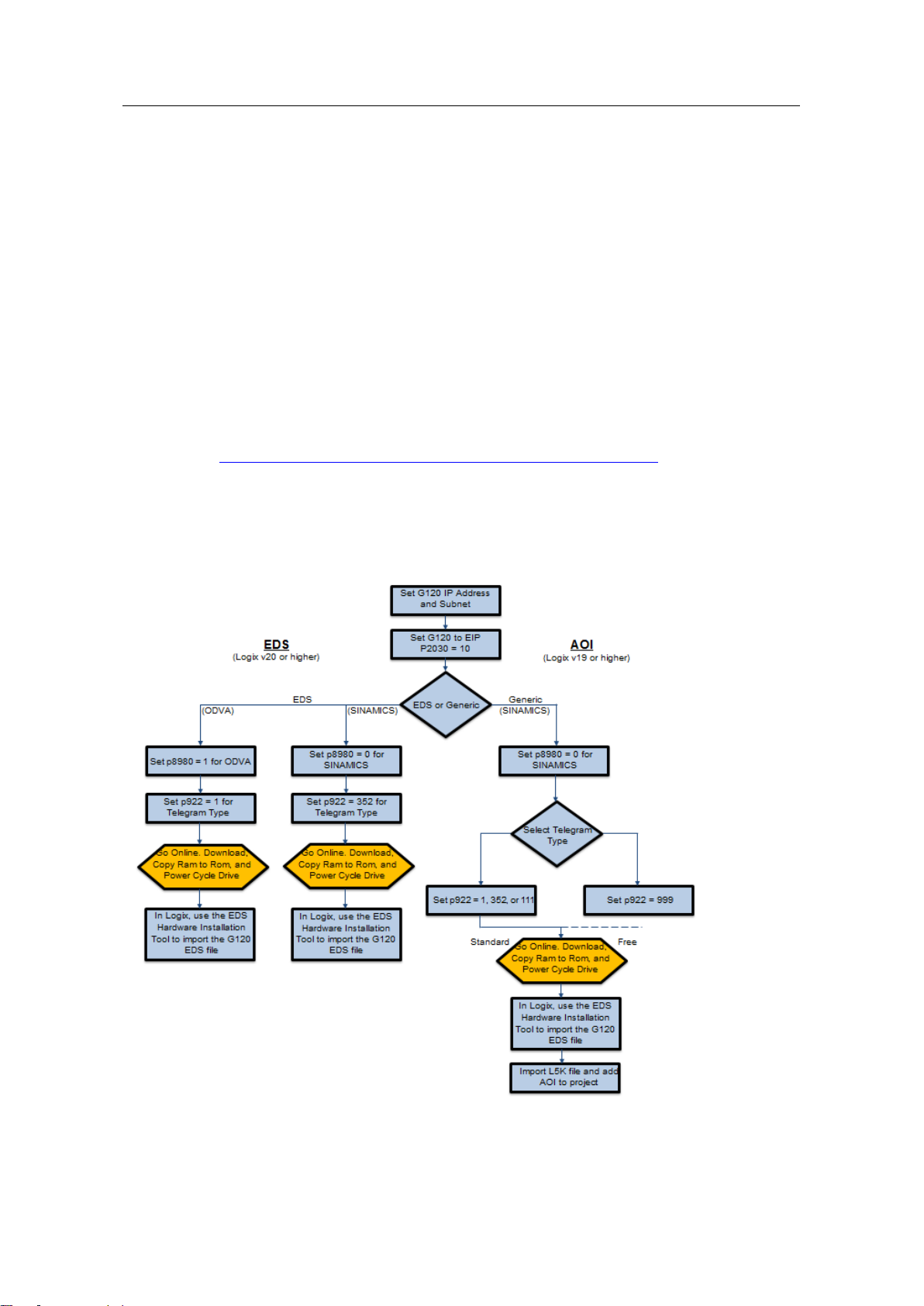
There are two main ways to configure a SINAMICS G drive to communicate over
EtherNet/IP. The approach described in this note uses Add On Instructions with a
Generic Ethernet Module. This approach requires version 19 or higher for RSLogix
5000.
Alternatively, the drive can be set up for ODVA type configuration. This allows the
user to import a ODVA G120 EDS file to use the drive as an ODVA AC drive
object. This approach requires version 20 or higher for RSLogix 5000. A newer
option is an EDS file that works with Telegram 352 and setting P8990 to 0
(SINAMICS). This EDS path is discussed in a separate application note.
https://support.industry.siemens.com/cs/ww/en/view/109761721
Refer to the diagram below for a general overview of the steps to configure
depending on method.
Figure 3-1
Page 8
3 Programming Overview
SINAMICS G: Control of a G120 with an Allen-Bradley controller
(Compact/ ControlLogix with RSLogix 5000) via EtherNet/IP
Entry-ID: 82843076, V4.0, 09/2018
8
Siemens AG
2015 All rights reserved
3.2 AOI’s for SINAMICS G Series drives
Add On Instructions have been designed for the RSLogix programming that mimic
standard telegrams used in SINAMICS G configurations. For most standard
applications the use of the AOI’s can greatly reduce the engineering time needed
to configure a system. The SINAMICS G series drives can also be freely
configured using the free telegram structure, dependent on application needs.
Figure 3-2
3.3 AOI Types
There are presently three Add On Instruction blocks that can be used for standard
telegrams T1, T352, and T111.
Table 3-1
Name
Standard Telegram #
Length
Simple Speed
Telegram 1
2 words in / 2 words out
Vector Speed
Telegram 352
6 words in / 6 words out
EPOS Control
Telegram 111
12 words in / 12 words out
Siemens AG Copyright 2015 All rights reserved
Page 9

4 SINAMICS G120 Add-On Instructions
SINAMICS G: Control of a G120 with an Allen-Bradley controller
(Compact/ ControlLogix with RSLogix 5000) via EtherNet/IP
Entry-ID: 82843076, V4.0, 09/2018
9
Siemens AG
2015 All rights reserved
4 SINAMICS G120 Add-On Instructions
4.1 Function Description
The drive control function block (AOI) described in this section is intended to
provide SINAMICS G series drive users with a quick and effective way to integrate
into an automation system where a Logix family controller is the primary control.
The AOI can also be used as a starting point since the user is free to customize it
to fit their specific application. The canned AOIs in this application guide have been
designed to seamlessly integrate with the PROFIdrive telegrams T1, T352, and
T111, commonly used for controlling SINAMICS G drives.
4.2 Telegram Descriptions
4.2.1 Telegram Type 1 for Simple Speed
This telegram is a standard PROFIdrive telegram of 2 words in length. It will control
the state of the drive by selecting the appropriate bits in the control word and set
the running speed in the speed setpoint word. For additional information on this
telegram and the details of its function, refer to the SINAMICS G120 Operating
Instructions Manual and List Manual.
Table 4-1 Telegram 1
WORD
INPUT
OUTPUT
1
Control Word 1
Status Word 1
2
Speed Setpoint value
Actual Speed value
4.2.2 Telegram Type 352 for Simple Speed
This telegram is a standard PROFIdrive telegram of 6 words in length. It is similar
to Telegram1 but with added functionality. There are 4 freely configurable words
available for control of the drive. These could be a separate control word or analog
values such as torque limitation or additional speed setpoint. Status to the PLC
contains a standard Status word, Speed, Current, Torque, Fault or Warning
number. For additional information on this telegram refer to the SINAMICS G120
Operating Instructions and List Manual.
Table 4-2: Telegram 352
WORD
INPUT
OUTPUT
1
Control Word 1
Status Word 1
2
Speed Setpoint Value
Actual Speed Value
3
User-Defined
ABS_Current
4
User-Defined
Torque
5
User-Defined
Warn_Code
6
User-Defined
Fault_Code
Page 10

4 SINAMICS G120 Add-On Instructions
SINAMICS G: Control of a G120 with an Allen-Bradley controller
(Compact/ ControlLogix with RSLogix 5000) via EtherNet/IP
Entry-ID: 82843076, V4.0, 09/2018
10
Siemens AG
2015 All rights reserved
4.2.3 Telegram Type 111 for EPOS mode
Telegram 111 is a standard PROFIdrive telegram for a positioning drive. It allows
sequence and control of the drive functions in addition to control of the positioning
function EPOS. 12 Words of data are exchanged with the drive where the 12th
word is reserved as a user selectable value. For detailed information on this
telegram refer to the SINAMICS List and Operating Instruction manuals for G120
CU250S-2 and CU250D-2. A license for EPOS is needed for CU250S-2; see the
link below for ordering an EPOS license.
https://support.industry.siemens.com/cs/ae/en/view/109755273
Table 4-3: SIEMENS telegram 111
WORD
Input
Output
1
Control Word 1
Status Word 1
2
Pos Control Word 1
Pos Status Word 1
3
Pos Control Word 2
Pos Status Word 2
4
Control Word 2
Status Word 2
5
Velocity Override
MELDW (Extended) Control
Word
6-7
MDI Position Setpoint
Position Actual Value
8-9
MDI Velocity Setpoint
Velocity Actual Value
10
MDI Percent Acceleration
Active Fault Number
11
MDI Percent Deceleration
Active Warning Number
12
User Selectable
User Selectable
Siemens AG Copyright 2015 All rights reserved
Page 11
4 SINAMICS G120 Add-On Instructions
SINAMICS G: Control of a G120 with an Allen-Bradley controller
(Compact/ ControlLogix with RSLogix 5000) via EtherNet/IP
Entry-ID: 82843076, V4.0, 09/2018
11
Siemens AG
2015 All rights reserved
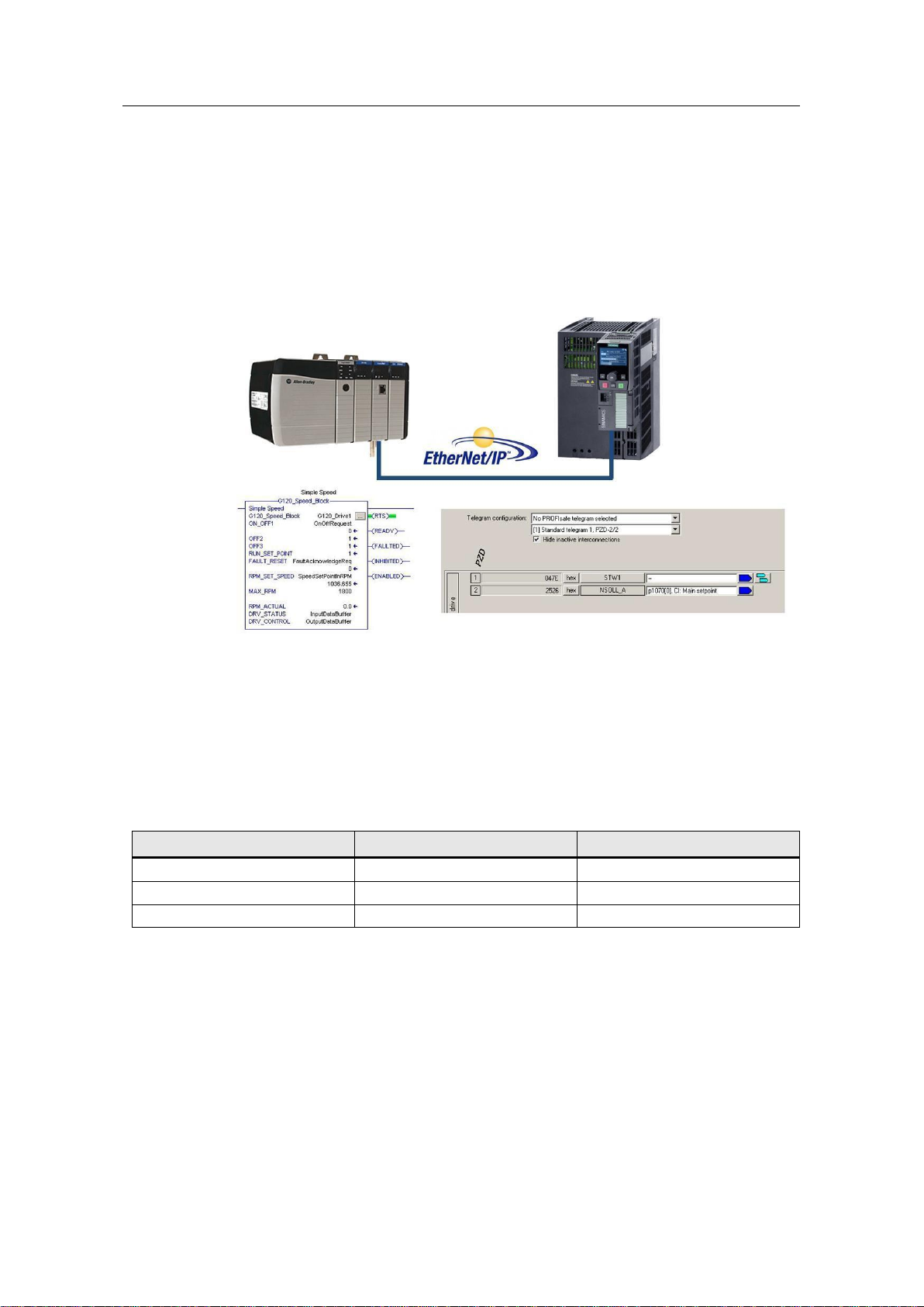
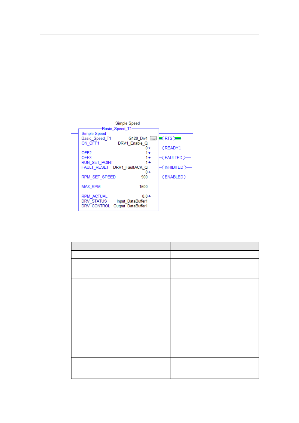
4.3 Basic Speed Control –Telegram 1
4.3.1 Functionality
The G120 Simple Speed Block provides an interface for basic speed control of a
SINAMICS drive via EtherNet/IP. The drive is configured for control using Standard
Telegram Type 1 which presets the drive speed reference and control word to be
sourced from the communication interface.
4.3.2 Schematic Ladder Representation
Figure 4-1 G120 Simple Speed Block
4.3.3 Input and Output Parameters
Table 4-4 Input parameters
Variable Name
Data Type
Description
G120_Speed_Block
Instance Data
ON_OFF1
BOOL
Drive Enable (ON/OFF1)
1 = Enable Drive
2 = Ramp down and disable drive
OFF2
BOOL
Coast Stop Command
0 = Off2 (Immediate disable)
1 = No OFF2 command
OFF3
BOOL
Fast Stop command
0 = OFF3 Fast ramp and disable drive
1 = No OFF3 command
RUN_SET_POINT
BOOL
Speed setpoint enable
0 = Setpoint disabled
1 = Setpoint enabled
FAULT_RESET
BOOL
Reset active drive faults
0 = No fault reset
1 = Reset fault(s) on rising edge
RPM_SET_SPEED
REAL
Speed setpoint in [rpm]
MAX_SPEED
REAL
Speed at 100% setpoint
Must be the same p2000 ( of the drive)
Page 12

4 SINAMICS G120 Add-On Instructions
SINAMICS G: Control of a G120 with an Allen-Bradley controller
(Compact/ ControlLogix with RSLogix 5000) via EtherNet/IP
Entry-ID: 82843076, V4.0, 09/2018
12
Siemens AG
2015 All rights reserved
Table 4-5 In/Out parameters
Variable Name
Data Type
Description
DRV_CONTROL
ARRAY
Array of 2 integers referenced to the two
outputs words of the drive telegram.
DRV_STATUS
ARRAY
Array of 2 integers referenced to the two
input words of the drive telegram.
Table 4-6 Output parameters
Variable Name
Data Type
Description
RTS
BOOL
Ready to Start
RDY_OP
BOOL
Ready for Operation
FAULTED
BOOL
Fault is Active
ENABLED
BOOL
Pulses are Enabled
RPM_ACTUAL
REAL
Actual Speed in RPM
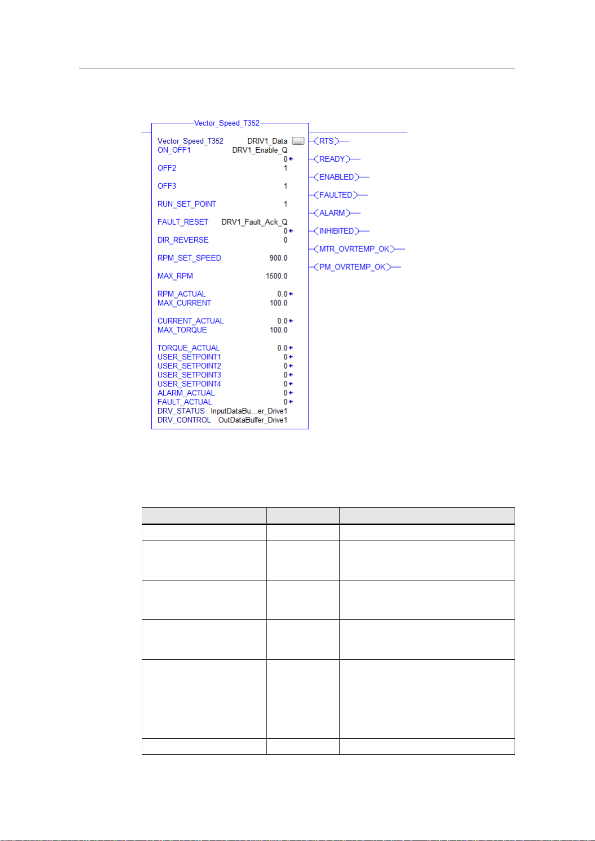
4.4 Speed Control –Telegram 352
4.4.1 Functionality
The Vector_Speed_352 Speed Block provides an interface for speed control via
EtherNet/IP. The Drive is configured for control using Standard Telegram Type 352
which presets the drive speed reference and control word to be sourced from the
communication interface. In addition there are four separate user defined control
words/setpoints available, as well as feedback for Current, Torque, Warning and
Fault values.
Page 13
4 SINAMICS G120 Add-On Instructions
SINAMICS G: Control of a G120 with an Allen-Bradley controller
(Compact/ ControlLogix with RSLogix 5000) via EtherNet/IP
Entry-ID: 82843076, V4.0, 09/2018
13
Siemens AG
2015 All rights reserved
4.4.2 Schematic Ladder Representation
Figure 4-2 Vector Speed T352
4.4.3 Input and Output parameters
Table 4-7 Input parameters
Vector_Speed_T352
Instance Data
ON_OFF1
BOOL
Drive Enable (ON/OFF1)
1 = Enable Drive
2 = Ramp down and disable drive
OFF2
BOOL
Coast Stop Command
0 = Off2 (Immediate disable)
1 = No OFF2 command
OFF3
BOOL
Fast Stop command
0 = OFF3 Fast ramp and disable drive
1 = No OFF3 command
RUN_SET_POINT
BOOL
Speed setpoint enable
0 = Setpoint disabled
1 = Setpoint enabled
FAULT_RESET
BOOL
Reset active drive faults
0 = No fault reset
1 = Reset fault(s) on rising edge
RPM_SET_SPEED
REAL
Speed setpoint in [rpm]
Page 14

4 SINAMICS G120 Add-On Instructions
SINAMICS G: Control of a G120 with an Allen-Bradley controller
(Compact/ ControlLogix with RSLogix 5000) via EtherNet/IP
Entry-ID: 82843076, V4.0, 09/2018
14
Siemens AG
2015 All rights reserved
MAX_RPM
REAL
Speed at 100% setpoint
Must be the same p2000 ( of the drive)
MAX_CURRENT
REAL
Current Feedback 100% value
Can be Scaled to P2002 or % (100.0)
MAX_TORQUE
REAL
Torque Feedback 100% value
Can be Scaled to P2003 or % (100.0)
USER_SETPOINT1
Integer
User Defined setpoint 0 to 16384
= 0 to 100% Value to Drive
USER_SETPOINT2
Integer
User Defined setpoint 0 to 16384
= 0 to 100% Value to Drive
USER_SETPOINT3
Integer
User Defined setpoint 0 to 16384
= 0 to 100% Value to Drive
USER_SETPOINT4
Integer
User Defined setpoint 0 to 16384
= 0 to 100% Value to Drive
Table 4-8 IN/OUT parameters
Variable Name
Data Type
Description
DRV_CONTROL
ARRAY
Array of 12 integers referenced to the
two outputs words of the drive telegram.
DRV_STATUS
ARRAY
Array of 12 integers referenced to the
two input words of the drive telegram.
Table 4-9 Output parameters
RTS
BOOL
Ready to Start
READY
BOOL
Ready for Operation
FAULTED
BOOL
Fault is Active
INHIBITED
BOOL
Power On Inhibited
ENABLED
BOOL
Pulses are Enabled
MTR_OVRTEMP_OK
BOOL
Motor Not Overtemp
PM_OVERTEMP_OK
BOOL
Power Module Overtemp
RPM_ACTUAL
REAL
Actual Speed in RPM
*Set Scale Value to 100 for Percentage
or set to P2000 Value
CURRENT_ACTUAL
REAL
Actual Current in AMP
*Set Scale Value to 100 for Percentage
or set to P2002 value
Page 15

4 SINAMICS G120 Add-On Instructions
SINAMICS G: Control of a G120 with an Allen-Bradley controller
(Compact/ ControlLogix with RSLogix 5000) via EtherNet/IP
Entry-ID: 82843076, V4.0, 09/2018
15
Siemens AG
2015 All rights reserved
4.5 EPOS Control
4.5.1 Functionality
The EPOS block interfaces to the SINAMICS Basic Positioner via EtherNet/IP. The
EPOS Positioner is used for absolute and relative positioning of linear and rotary
axes. The CU250D-2 and CU250S-2 G120 controllers are capable of EPOS
control.
The AOI provides a direct interface to EPOS control. Note that the drive must be
referenced before absolute positioning is allowed. State control and sequencing is
not provided. Additional user logic is required to synchronize the state of the drive
with the positioning functions.
4.5.2 Schematic Ladder Representation
Figure 4-3 EPOS block
Page 16

4 SINAMICS G120 Add-On Instructions
SINAMICS G: Control of a G120 with an Allen-Bradley controller
(Compact/ ControlLogix with RSLogix 5000) via EtherNet/IP
Entry-ID: 82843076, V4.0, 09/2018
16
Siemens AG
2015 All rights reserved
4.5.3 Input and Output parameters
Table 4-10 Input parameters
S120_EPOS_BLOCK
Instance Data
ON
BOOL
Drive Enable (ON/OFF1)
1 = Enable Drive
2 = Ramp down and disable drive
FAULT_RESET
BOOL
Reset Active Fault(s)
0 = No Fault Reset
1 = Reset Fault on Rising Edge
JOG_FWD
BOOL
0 = No Jog
1 = Jog Forward at speed in P2586
JOG_REV
BOOL
0 = No Jog
1 = Jog Reverse at speed in P2585
REF_START
BOOL
Referencing Start
0 = No Referencing
1 = Enable Referencing
MDI_START
BOOL
1 = Enable MDI Mode
0 = No MDI mode
Note: All motion should be
completed before disable to avoid
fault.
MDI_SETUP
BOOL
Enable MDI Setup Mode
0 = No Setup Mode
1 = Enable MDI Setup Mode
MDI_POS_TYPE
BOOL
Select MDI Positioning Type 0 =
Absolute Positioning
1 = Relative Positioning
MDI_FWD_DIR
BOOL
Enable Forward Direction
MDI_REV_DIR
BOOL
Enable Reverse Direction
Note: If Both MDI_FWD_DIR and
MDI_REV_DIR are True, shortest
path is selected for absolute
positioning
MDI_EDGE_TRIG
BOOL
Trigger Loading of Setpoints
Load executed on rising edge of
input transition
MDI_CONSTANT_TRIG
BOOL
Select Setpoint loading type
0 = The setpoint are accepted on
the rising edge of the
MDI_EDGE_TRIG input
1 = Setpoints are continuously
loaded. (Absolute Positioning only)
INTERMEDIATE_STOP
BOOL
Stop motion. The canceling the
motion command.
0 = Stop motion
1 = Allow motion
POSITION_SETPOINT
DINT
Position Setpoint in [LU]
ACCEL_RATE
REAL
% of Nominal Acceleration
DECEL_RATE
REAL
% of Nominal Deceleration
V_OVERRIDE
REAL
% of Override for Velocity
Page 17

4 SINAMICS G120 Add-On Instructions
SINAMICS G: Control of a G120 with an Allen-Bradley controller
(Compact/ ControlLogix with RSLogix 5000) via EtherNet/IP
Entry-ID: 82843076, V4.0, 09/2018
17
Siemens AG
2015 All rights reserved
Table 4-11 IN/OUT parameters
Variable Name
Data Type
Description
DRV_CONTROL
ARRAY
Array of 12 integers referenced to
the two outputs words of the drive
telegram.
DRV_STATUS
ARRAY
Array of 12 integers referenced to
the two input words of the drive
telegram.
Table 4-12 Output parameters
RTS
BOOL
Ready to Start
RDY_OP
BOOL
Ready for Operation
ENABLED
BOOL
Pulses are Enabled at Motor Output
FAULTED
BOOL
Fault is Active
ALARM
BOOL
Alarm is Active
JOGGING
BOOL
Axis is Jogging
HOMING
BOOL
Referencing Mode Enabled
REFERENCED
BOOL
Axis is Referenced
MDI_POS
BOOL
MDI Mode is Active
MDI_SETUP_ON
BOOL
MDI Setup Mode is Active
TARGET_REACHED
BOOL
Position Actual is within the position
window set
FAULT_NUMBER
INT
Active Fault number; 0 if no Fault
ALARM_NUMBER
INT
Active Alarm Number; 0 if no Alarm
POSITION_ACTUAL
DINT
Position value in [LU]
SPEED_ACT_PCT
REAL
Speed in percent of P2000
TORQUE_ACTUAL
REAL
Torque value in percent of P2002
This value is mapped to word 12 of the
telegram status data. For the torque to
be displayed, Parameter 2051.11 must
be connected to r80.
Page 18

4 SINAMICS G120 Add-On Instructions
SINAMICS G: Control of a G120 with an Allen-Bradley controller
(Compact/ ControlLogix with RSLogix 5000) via EtherNet/IP
Entry-ID: 82843076, V4.0, 09/2018
18
Siemens AG
2015 All rights reserved
4.6 UDTs
UDTs are provided as representing the typical control and status words used for
Telegrams implemented by the AOI provided. These cannot be utilized when using
the provided EDS file. The UDTs can also be used independently to map IO data
sent and received by the drive. The user application can directly control telegram
words and bits to accomplish control functions not included in the AOIs provided by
Siemens. This is the case when using user-defined telegrams (free telegram
configuration with BICO) to exchange data with the drives.
Page 19

5 Drive Configuration
SINAMICS G: Control of a G120 with an Allen-Bradley controller
(Compact/ ControlLogix with RSLogix 5000) via EtherNet/IP
Entry-ID: 82843076, V4.0, 09/2018
19
Siemens AG
2015 All rights reserved
5 Drive Configuration
Commissioning of the G120 drives is not in the scope of this document. Refer to
the “Getting Started Manual” for your G120 model to assist in the commissioning of
the drive(s). See the link below for G120 Getting Started manuals.
https://support.industry.siemens.com
5.1 Configuring IP Address of CU
The IP address can be set from Starter. Make sure that your PC is in the same
Subnet as address desired for the G120 and AB PLC.
Figure 5-1 TCP/IPv4 Address for PC or PG
Figure 5-2 Use Accessible Nodes to Find CU250. Right click on Node to Open address
setting.
Page 20

5 Drive Configuration
SINAMICS G: Control of a G120 with an Allen-Bradley controller
(Compact/ ControlLogix with RSLogix 5000) via EtherNet/IP
Entry-ID: 82843076, V4.0, 09/2018
20
Siemens AG
2015 All rights reserved
Figure 5-3 Set IP Address for the G120 as shown
Figure 5-4 Bring the Drive Unit into Project. Choose Select and then Accept.
Figure 5-5 The G120 controller is now in the Project Tree. Go online to upload Power
Module properties.
Page 21

5 Drive Configuration
SINAMICS G: Control of a G120 with an Allen-Bradley controller
(Compact/ ControlLogix with RSLogix 5000) via EtherNet/IP
Entry-ID: 82843076, V4.0, 09/2018
21
Siemens AG
2015 All rights reserved
Figure 5-6 Load HW Configuration to PG.
Figure 5-7 Go offline with the G120 and Complete Commissioning.
Figure 5-8
Figure 5-9 Commission Drive Object(s) as needed.
Note the message frame in next section for the Example Dual Axis Demo program.
Refer to the documentation link in previous section if commissioning assistance is
needed.
8. Open the Communication folder. Set Telegram to desired telegram (352 in this
example) and set Protocol to 10 EtherNet/IP. Alternately this can be done in Expert
List via parameters P922 for telegram type and P2030 for protocol type.
Page 22

5 Drive Configuration
SINAMICS G: Control of a G120 with an Allen-Bradley controller
(Compact/ ControlLogix with RSLogix 5000) via EtherNet/IP
Entry-ID: 82843076, V4.0, 09/2018
22
Siemens AG
2015 All rights reserved
Figure 5-10
Figure 5-11 . Highlight the Drive Unit, Go Online, and download to the G120.
Figure 5-12 Complete the Motor ID and Rotation Check.
Page 23

5 Drive Configuration
SINAMICS G: Control of a G120 with an Allen-Bradley controller
(Compact/ ControlLogix with RSLogix 5000) via EtherNet/IP
Entry-ID: 82843076, V4.0, 09/2018
23
Siemens AG
2015 All rights reserved
Figure 5-13 Save RAM to ROM and Upload to PC
14. Power Cycle the G120; the Control Unit must be powered off to set the
communication protocol to EtherNet/IP. Wait sufficient time that the Control Unit
powers down. The CU will be ready for EtherNet/IP communication when power is
restored.
5.2 Using a Freely Configurable Telegram
Selectable Telegrams such as T352 offer easy parameter mapping for drive
control. Binectors or Connectors terminated by the telegram can be changed if the
telegram is changed to “Free Telegram” (P922 = 999).
It is possible to configure a custom telegram to fit a specific application
requirement. The custom configuration can be accomplished using one the
methods listed.
1. Using a standard telegram as a template and changing the configuration
manually.
2. Selecting the input and output data length and connecting the telegram words
in the communications window of the drive configuration.
3. Configuration by Script execution. A script can be written in Starter that
configures the telegram size and connections required. The script is then
executed in Starter, configuring the drive.
Parameter r2067 displays the number of PZDs the controller detected to be part of
the telegram. The Input and Output data length must match the values in r2067 of
the drive. For example, if telegram T352 was used as a basis for a free Telegram, it
would have 4 User Defined Words to the drive from the PLC. If these words are not
used for connections such as Added Speed Setpoint, Torque Setpoint, or Torque
Limits, then they must be terminated to unused Connector Input Parameters.
Figure 5-14
Page 24

5 Drive Configuration
SINAMICS G: Control of a G120 with an Allen-Bradley controller
(Compact/ ControlLogix with RSLogix 5000) via EtherNet/IP
Entry-ID: 82843076, V4.0, 09/2018
24
Siemens AG
2015 All rights reserved
5.2.1 Example of "Free telegram" commissioning
1. Drive commissioned with T352 and change then parameter 922 Telegram Type
set to [999] for use with Free Telegram
Figure 5-15
2. Check r2067 in the Expert List. All words being sent to the drive from the PLC
and from the PLC to the drive must be accounted for. Vector Speed uses 6 words
IN / 6 words OUT. That message frame must agree with r2067 in the Expert List.
Figure 5-16 Example using T352 AOI for Free Telegram before terminating spare words
3. Words not being used must be terminated to “Dummy Parameters”. These
words could be used for more useful connections such as Added Speed Setpoint,
Torque Limits, or Torque Setpoints. This programming can be done via scripting,
Expert List, or the Starter GUI.
Figure 5-17 Example of spare word holder script using p20110 (free blocks multiplier)
Figure 5-18 The values in r2067 after terminating extra words and downloading
4. After downloading, cycle power to the drive.
NOTE
The Spare Words In or Out for a standard telegram can be freely used by the
user. It is only necessary to use a free telegram if changing the mapped value of
a Standard Telegram or making a User Defined Telegram.
Page 25

6 Configuring a Generic Ethernet Module
SINAMICS G: Control of a G120 with an Allen-Bradley controller
(Compact/ ControlLogix with RSLogix 5000) via EtherNet/IP
Entry-ID: 82843076, V4.0, 09/2018
25
Siemens AG
2015 All rights reserved
6 Configuring a Generic Ethernet Module
6.1 Adding a new module in RSLogix
A Generic IO module is used to configure the cyclic data exchange between the
automation controller and the SINAMICS drive without an EDS file.
6.1.1 Inserting the module in an RSLogix project
Table 6-1 Inserting the Generic Ethernet Module
1.
Insert a module by rightclicking the network interface
in the IO configuration section
of the Project tree.
2.
In the “Select Module” dialog
box, use the “Find” function to
search for the term
“GENERIC”.
Select the “Generic Ethernet
Module” to be inserted
Page 26

6 Configuring a Generic Ethernet Module
SINAMICS G: Control of a G120 with an Allen-Bradley controller
(Compact/ ControlLogix with RSLogix 5000) via EtherNet/IP
Entry-ID: 82843076, V4.0, 09/2018
26
Siemens AG
2015 All rights reserved
6.1.2 Configuring network parameters
Table 6-2 Configuring the Network Parameters
The module name should identify the
G120 to allow easy selection from
other modules configured in the
controller. It is also the name used for
the controller level tag that will hold
the data. Use the Description box to
describe the Drive objects contained
in the module.
The data exchange format should be
set to Integer (INT).
Enter the IP Address of the G120.
The Connection Parameters section
configures the IO Assemblies. The
Assembly Instances should always be
101 through 103 for the Input, Output
and Configuration Assembly
respectively. The size of the Input and
Output assemblies is the total number
of words. For Standard Telegram 1,
there are 2 words in and 2 words out.
For Telegram 352 there are 6 words
in and 6 words out.
In this example the speed block
telegram for T352 is shown.
Page 27

6 Configuring a Generic Ethernet Module
SINAMICS G: Control of a G120 with an Allen-Bradley controller
(Compact/ ControlLogix with RSLogix 5000) via EtherNet/IP
Entry-ID: 82843076, V4.0, 09/2018
27
Siemens AG
2015 All rights reserved
6.1.3 Connection Parameters
Table 6-3 Setting the connection parameters
The Requested Packet Interval (RPI)
is the rate at which the controller will
exchange data with the drive. The
G120 can operate with a RPI set to a
minimum of 5 ms. In this application
we will use a value of 10 ms.
Unicast is selected as the exchange
method.
6.1.4 Using IO Data
The IO data is available as an array of integers in the controller tags section of the
project tree. They are included as a tag list with the L5K file.
Figure 6-1 Controller Tags for new module
Page 28

7 Using AIOs in a new application
SINAMICS G: Control of a G120 with an Allen-Bradley controller
(Compact/ ControlLogix with RSLogix 5000) via EtherNet/IP
Entry-ID: 82843076, V4.0, 09/2018
28
Siemens AG
2015 All rights reserved
7 Using AIOs in a new application
7.1 Importing AIOs
The AOIs provided with the sample application can be easily integrated into a new
or existing user program by importing the instructions using L5K files.
7.1.1 Installing L5K Files in RSLogix
Table 7-1
Import the AOI into the Add-On
Instructions folder. Right click the AddOn Instructions folder in the project tree
and select the Import Add-On
Instruction option.
Select the required L5K file for the
desired Instruction and click Import.
Review the Import configuration and
click OK.
The Project should now show the
imported Instruction. Notice that UDTs
required for the instruction have also
been imported. These UDTs can also
be used to create additional variables
and aliases.
Page 29

7 Using AIOs in a new application
SINAMICS G: Control of a G120 with an Allen-Bradley controller
(Compact/ ControlLogix with RSLogix 5000) via EtherNet/IP
Entry-ID: 82843076, V4.0, 09/2018
29
Siemens AG
2015 All rights reserved
7.2 Using the AOI
7.2.1 Adding AOI to an RSLogix Program
Table 7-2 Using the G120 Simple Speed Block
Add the AOI to a new rung by dragging
from the project tree.
Declare and assign the instance data
variable. The new tag can be created
as a local program tag with a name that
clearly identifies the drive data. Right
click the field next to
G120_Speed_Block and select New
Tag.
Give the tag a descriptive name and
select OK.
Page 30

7 Using AIOs in a new application
SINAMICS G: Control of a G120 with an Allen-Bradley controller
(Compact/ ControlLogix with RSLogix 5000) via EtherNet/IP
Entry-ID: 82843076, V4.0, 09/2018
30
Siemens AG
2015 All rights reserved
7.2.2 I/O Interface
Connecting the instruction to the Controller IO tags is accomplished by moving the
IO data into the AOI Interface.
Figure 7-1 Configuring AOI Communication
The second rung holds the AOI. The local variables “InputDataBuffer” and
“OutputDataBuffer” are used as storage for the AOI to receive and send data to the
Controller IO tags.
The first rung copies the IO data for the drive to a local variable to be used by the
AOI as inputs in the “DRV_STATUS” parameters. “DRV_STATUS” and
“DRV_CONTROL” are declared as INOUT parameters and are therefore passed
by reference.
The third rung holds the copy command that moves the control data from the
working variable “OutputDataBuffer” to the controller IO tag.
All AOIs provided will use this method of data exchange with IO containing the
drive data. Additional access to the control data can be performed before the data
is copied to the IO Tag. This allows the user to utilize features already mapped in
the telegram that are not controlled by the AOI. In a similar manner the Status data
can be accessed by the user program
Page 31

8 Drive Parameter Access
SINAMICS G: Control of a G120 with an Allen-Bradley controller
(Compact/ ControlLogix with RSLogix 5000) via EtherNet/IP
Entry-ID: 82843076, V4.0, 09/2018
31
Siemens AG
2015 All rights reserved
8 Drive Parameter Access
8.1 Explicit Messaging
In many applications it is necessary to read or write parameters in the drive. This
allows increased flexibility in implementation of the machine functionality.
To allow this occasional (acyclic) data exchange of drive and motor parameters,
the drive supports explicit messaging.
The MSG instruction can read from or write to a parameter by accessing the drive’s
communication object. When parameterizing the MSG instruction, below are some
important parameters:
Class = 401hex (for G120)
Instance = parameter number
p1027 = instance 1027
Attribute = parameter index number (hex) Index
Index 0 = attribute 0
Index 1 = attribute 1
…
Index 65535 = attribute FFFFh
Get attribute single = read a parameter
Set attribute single = write a parameter
Page 32

8 Drive Parameter Access
SINAMICS G: Control of a G120 with an Allen-Bradley controller
(Compact/ ControlLogix with RSLogix 5000) via EtherNet/IP
Entry-ID: 82843076, V4.0, 09/2018
32
Siemens AG
2015 All rights reserved
8.2 Using the MSG Instruction
NOTE
It is a good idea to one-shot the message requests (e.g. with a flasher). If the
rung for the MSG instruction is always true, the communication board can get
overwhelmed and fault out.
Table 8-1
MSG Instruction:
Insert the MSG instruction.
Instruction Tag:
Create a controller scope tag for the
instruction in the Tag tab of the
message configuration dialog box.
This tag contains the working memory
area for the MSG instruction.
Message Type:
Select the CIP Generic message
type.
Page 33

8 Drive Parameter Access
SINAMICS G: Control of a G120 with an Allen-Bradley controller
(Compact/ ControlLogix with RSLogix 5000) via EtherNet/IP
Entry-ID: 82843076, V4.0, 09/2018
33
Siemens AG
2015 All rights reserved
Service Type:
Select “Get Attribute Single” to read
the parameter or “Set Attribute
Single” to write to the parameter.
Class: 401 (hex)
Instance:
This is the parameter number of the
object, in Starter. E.g. DC Link
voltage (p26).
Page 34

8 Drive Parameter Access
SINAMICS G: Control of a G120 with an Allen-Bradley controller
(Compact/ ControlLogix with RSLogix 5000) via EtherNet/IP
Entry-ID: 82843076, V4.0, 09/2018
34
Siemens AG
2015 All rights reserved
Attribute:
This is the parameter index. For
parameters without an index, use “0”.
Destination:
For reading a parameter select a
Controller scope tag where the
value will be written.
If writing a value to the parameter,
select a tag in the Source element
entry.
Source Length (writing only): When
writing to a parameter, make sure
the source length matches the
parameter that you are trying to
write to.
INT = 2 Bytes (16 bit)
REAL = 4 Bytes (32 bit)
Page 35

8 Drive Parameter Access
SINAMICS G: Control of a G120 with an Allen-Bradley controller
(Compact/ ControlLogix with RSLogix 5000) via EtherNet/IP
Entry-ID: 82843076, V4.0, 09/2018
35
Siemens AG
2015 All rights reserved
Make sure the data type of the tag
(source/destination) matches the
data type of the parameter.
INT = 2 Bytes (16 bit)
REAL = 4 Bytes (32 bit)
To figure out the data type of the
parameter, search for the parameter
in the Starter help tool, or refer to the
List Manual.
Page 36

8 Drive Parameter Access
SINAMICS G: Control of a G120 with an Allen-Bradley controller
(Compact/ ControlLogix with RSLogix 5000) via EtherNet/IP
Entry-ID: 82843076, V4.0, 09/2018
36
Siemens AG
2015 All rights reserved
Path:
In the communication tab enter the
name of the IO node for the G120.
Use the Browse option to find the
node in the Project Tree.
Page 37

9 Troubleshooting
SINAMICS G: Control of a G120 with an Allen-Bradley controller
(Compact/ ControlLogix with RSLogix 5000) via EtherNet/IP
Entry-ID: 82843076, V4.0, 09/2018
37
Siemens AG
2015 All rights reserved
9 Troubleshooting
9.1 I can’t go online with the drive in Starter using the Ethernet cable.
Do you have firmware v4.7 or above on the drive unit? Communication from Starter
to the drive using Ethernet/IP is only support with firmware v4.7 or later on the
G120. If you are using v4.6, then you will need to use the USB cable to connect to
the drive with Starter.
9.2 The drive and the PLC are not communicating
Figure 9-1
Figure 9-2
1. Check the LED lights
a. PLC: Is the I/O light solid green?
b. G120: Is the Link1 light solid green?
c. This means that the drive is communicating and it is another issue
2. Is the drive set for EIP (G120: p2030 = 10)?
a. A power cycle is required after changing p2030.
Page 38

9 Troubleshooting
SINAMICS G: Control of a G120 with an Allen-Bradley controller
(Compact/ ControlLogix with RSLogix 5000) via EtherNet/IP
Entry-ID: 82843076, V4.0, 09/2018
38
Siemens AG
2015 All rights reserved
3. Are there duplicate IP addresses on the network?
a. Verify IP addresses (accessible nodes, edit Ethernet nodes, etc.)
4. Did you parameterize the Generic Ethernet Module in RSLogix 5000 correctly?
Figure 9-3
a. Do you have the “Comm. Format” set to Data –INT, or accidentally set
to Data-DINT?
Figure 9-4
b. Do the Connection Parameters (addresses and length) match the drive
telegram?
Figure 9-5
5. Could it be a bad Ethernet cable?
Page 39

9 Troubleshooting
SINAMICS G: Control of a G120 with an Allen-Bradley controller
(Compact/ ControlLogix with RSLogix 5000) via EtherNet/IP
Entry-ID: 82843076, V4.0, 09/2018
39
Siemens AG
2015 All rights reserved
6. Are there faults on the drive?
a. Check drive status LEDs
b. Check drive diagnostics for faults
7. Are all Drive Enables (OFF1/OFF2/OFF3) enabled?
Page 40

10 Glossary
SINAMICS G: Control of a G120 with an Allen-Bradley controller
(Compact/ ControlLogix with RSLogix 5000) via EtherNet/IP
Entry-ID: 82843076, V4.0, 09/2018
40
Siemens AG
2015 All rights reserved
10 Glossary
AOI (Add On Instruction): Commonly used logic for a task that is encapsulated
into a block to be reused in RSLogix programs
BICO: BICO technology (Binector Connector Technology) allows the drive to be
adapted to a wide variety of requirements. Digital and analog signals which can be
connected freely by means of BICO parameters are identified by the prefix BI, BO,
CI or CO in their parameter name.
Control Word: Arrangement of two bytes used to command the drive sequence
control (referred to as STW1 in SINAMICS Documentation)
EDS File: Text files used by RSLogix network configuration tool to help identify
products and easily integrate them on a network. All available G120 EDS files can
be found here:
https://support.industry.siemens.com/cs/ww/en/view/78026217
Free Telegrams: Send and receive telegrams that can be configured as required
by using BICO technology to interconnect the send and receive process data.
L5K file: File type used for importing an AOI into RSLogix program
MDI (Motion Direct Input): Direct setpoint input function for positioning
ODVA: Open DeviceNet Vendors Association. Organization that supports network
technologies built on the Common Industrial Protocol (CIP™) — DeviceNet™,
EtherNet/IP™, CompoNet™, and ControlNet™
PN Interface: PROFINET interface
PROFIdrive: Device profile to provide standardization of drive telegram type thus
minimizing integration and commissioning time and effort.
Siemens Standard Telegrams: Structured in accordance with manufacturer
specification with the internal process data links automatically set up in accordance
with the telegram number setting.
Standard PROFIdrive Telegrams: Structured in accordance with PROFIdrive
profile with the internal process data links automatically set up in accordance with
the telegram number setting.
STARTER: Software for Siemens SINAMICS drives configuration and diagnostics
Status Word: Arrangement of two bytes used to report the current status of the
drive (referred to as ZSW1 in SINAMICS Documentation)
UDT: User Defined Type; holds data relevant to the device
Page 41

11 Appendix
SINAMICS G: Control of a G120 with an Allen-Bradley controller
(Compact/ ControlLogix with RSLogix 5000) via EtherNet/IP
Entry-ID: 82843076, V4.0, 09/2018
41
Siemens AG
2015 All rights reserved
11 Appendix
11.1 Service and support
Industry Online Support
Do you have any questions or need assistance?
Siemens Industry Online Support offers round the clock access to our entire
service and support know-how and portfolio.
The Industry Online Support is the central address for information about our
products, solutions and services.
Product information, manuals, downloads, FAQs, application examples and videos
– all information is accessible with just a few mouse clicks:
https://support.industry.siemens.com/
Technical Support
The Technical Support of Siemens Industry provides you fast and competent
support regarding all technical queries with numerous tailor-made offers
– ranging from basic support to individual support contracts. Please send queries
to Technical Support via Web form:
https://www.siemens.com/industry/supportrequest
SITRAIN – Training for Industry
We support you with our globally available training courses for industry with
practical experience, innovative learning methods and a concept that’s tailored to
the customer’s specific needs.
For more information on our offered trainings and courses, as well as their
locations and dates, refer to our web page:
https://www.siemens.com/sitrain
Service offer
Our range of services includes the following:
• Plant data services
• Spare parts services
• Repair services
• On-site and maintenance services
• Retrofitting and modernization services
• Service programs and contracts
You can find detailed information on our range of services in the service catalog
web page:
https://support.industry.siemens.com/cs/sc
Industry Online Support app
You will receive optimum support wherever you are with the "Siemens Industry
Online Support" app. The app is available for Apple iOS, Android and Windows
Phone:
https://support.industry.siemens.com/cs/ww/en/sc/2067
Page 42

11 Appendix
SINAMICS G: Control of a G120 with an Allen-Bradley controller
(Compact/ ControlLogix with RSLogix 5000) via EtherNet/IP
Entry-ID: 82843076, V4.0, 09/2018
42
Siemens AG
2015 All rights reserved
11.2 Change documentation
Table 11-1
Version
Date
Modifications
V1.0
05/2013
First version
V1.2b
10/2014
Draft for Revision
V2.0
03/2015
Add in explicit messaging Added in troubleshooting
V3.0
07/2015
Added in G130/G150 information
Removed references to USB
connection
Removed the appendix and added the “edit ethernet node”
to the main documentation
Updated T352 block Added in T111 block
V4.0
09/2018
Removed G130/ G150 information. This type information
/configuration in the S120 note for AB Controller. Upgraded
Setting Ethernet Address and other sections.
 Loading...