

Siemens SINAMICS G List Manual

List Manual 12.2004 Edition
sinamics
SINAMICS G


s
Preface
SINAMICS
SINAMICS G List Manual
Manual
Valid as from
Drive Software version
SINAMICS S 2.2
Parameters
1
2
Function diagrams
3
Faults and Alarms
List of Abbreviations
References
Index
Edition 12.2004
Safety Information
This manual contains information that you must observe for your personal safety and to avoid material
damage. The information is indicated by a warning triangle and displayed as follows according to the level
of risk:
Danger
Indicates an imminently hazardous situation which, if not avoided, will result in death or serious injury or
in substantial property damage.
Warning
Indicates a potentially hazardous situation which, if not avoided, could result in death or serious injury or
in substantial property damage.
Caution
Used with the safety alert symbol indicates a potentially hazardous situation which, if not avoided, may
result in minor or moderate injury or in property damage.
Caution
Used without safety alert symbol indicates a potentially hazardous situation which, if not avoided, may
result in property damage.
Notice
Used without the safety alert symbol indicates a potential situation which, if not avoided, may result in an
undesirable result or state.
Qualified Personnel
The device must only be commissioned and operated by qualified personnel. For the purpose of the
safety information in this documentation, a "qualified person" is someone who is authorized to operate,
ground, and tag devices, systems, and circuits in accordance with established safety procedures.
Proper Use
Observe the following information:
Warning
The device must only be used for the applications specified in the catalog and in the technical description.
The device must only be used in conjunction with external devices and components recommended or
approved by Siemens.
The successful and safe operation of this device depends on correct transport, proper storage and installation, as well as careful operation and maintenance.
Trademarks
SIMATIC®, SIMATIC HMI®, SIMATIC NET®, SIMODRIVE®, SIMOTION®, SINAMICS® and
SINUMERIK
The designations in this documentation may be trademarks whose use by third-parties for their own
purposes may infringe the rights of the owner.
®
are trademarks of SIEMENS AG.
Copyright Siemens AG 2004 All Rights Reserved
The reproduction, transmission or use of this document or its contents
is not permitted without express written authority. Offenders will be liable for damages. All rights, including rights created by patent grant
or registration or a utility model or design, are reserved.
Siemens AG
Automation & Drives
Motion Control Systems
P.O. Box 3180, D-91050 Erlangen
Federal Republic of Germany
Exclusion of Liability
We have conscientiously checked the contents of this manual to ensure that they coincide with the hardware and software described.
Since deviations cannot be precluded entirely, we cannot guarantee
complete conformance. However, the data in this manual is reviewed
regularly and any necessary corrections included in subsequent
editions. We are grateful for any recommendations or suggestions.
Siemens AG 2004
Subject to technical changes without notice.
Siemens Aktiengesellschaft SINAMICS G List Manual
Preface
Information about the SINAMICS documentation
The SINAMICS documentation is divided into the following areas:
• General documentation / catalogs
• User documentation
• Manufacturer/service documentation
• Electronic documentation
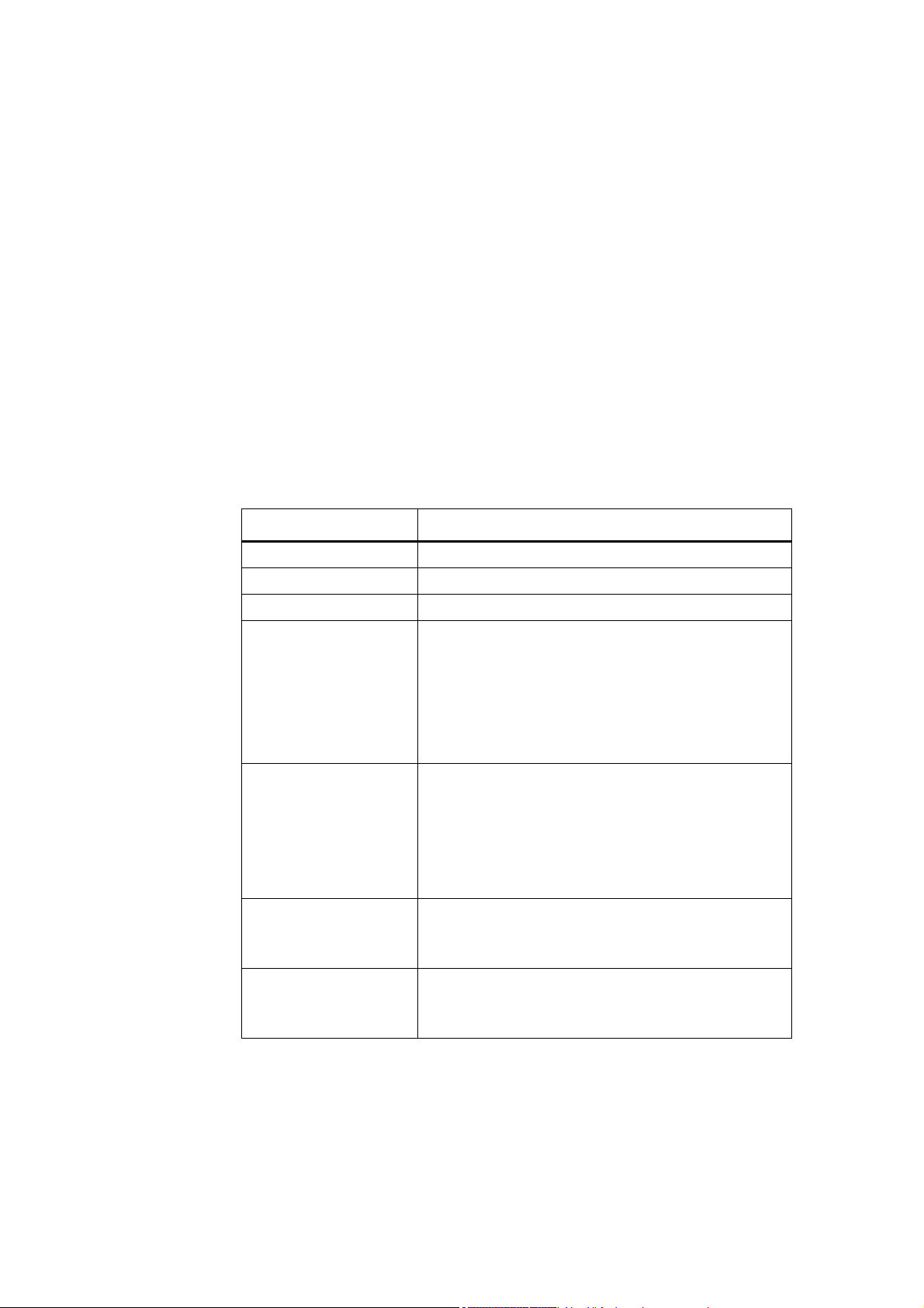
Table Preface-1Useful phases and available documentation/tools
Useful phase Document/Tool
Exploratory SINAMICS S Sales Documentation
Planning/configuration SIZER configuration tool
Decision/ordering SINAMICS S Catalog
Installation/assembly • SINAMICS S120 Equipment Manual for Control Units
and Supplementary System Components
• SINAMICS S120 Equipment Manual Power Modules
Booksize
• SINAMICS S120 Equipment Manual Power Modules
Chassis
• SINAMICS S150 Operating Manual
Commissioning • STARTER parameterization and commissioning tool
• SINAMICS S120 Getting Started
• SINAMICS S120 Commissioning Manual
• SINAMICS S120 Commissioning Manual CANopen
• SINAMICS S List Manual
• SINAMICS S150 Operating Manual
Usage/operation • SINAMICS S120 Commissioning Manual
• SINAMICS S List Manual
• SINAMICS S150 Operating Manual
Maintenance/servicing • SINAMICS S120 Commissioning Manual
• SINAMICS S List Manual
• SINAMICS S150 Operating Manual
This documentation is part of the technical customer documentation for
SINAMICS. All documents can be obtained separately.
SINAMICS G List Manual, Edition 12.2004
Preface-5 Siemens AG 2004 All Rights Reserved

Preface
Audience
You can obtain detailed information about the documents named in the documentation overview and other documents available for SINAMICS from your local Siemens office.
In the interests of clarity, this documentation does not contain all the detailed
information for all product types and cannot take into account every possible
aspect of installation, operation, or maintenance.
The contents of this documentation are not part of an earlier or existing agreement, a promise, or a legal agreement, nor do they change this. All obligations
entered into by Siemens result from the respective contract of sale that contains
the complete and sole valid warranty arrangements. These contractual warranty
provisions are neither extended nor curbed as a result of the statements made in
this documentation.
This documentation is aimed at machine manufacturers, commissioning engineers, and service personnel who use SINAMICS.
Objective
This manual contains the comprehensive information about parameters, function
diagrams and faults and alarms required to commission and service the system.
It must be used as a supplementary document to the other manuals and tools
available for the product.
Finding Your Way Around
The following guides are provided to help you locate information in this manual:
1. Table of contents
− General table of contents for complete manual (after the preface).
− Table of contents for function diagrams (Section 2.1).
2. List of Abbreviations
3. References
4. IndexGlossary
Preface-6
Siemens AG 2004 All Rights Reserved
SINAMICS G List Manual, Edition 12.2004

Technical Support
If you have any further questions, please call our hotline:
Tel. +49 (0) 180 5050 - 222
Fax: +49 (0) 180 5050 - 223
Internet: http://www.siemens.de/automation/support-request
Please send any questions about the documentation (e.g. suggestions for
improvement, corrections) to the following fax number or email address:
Fax:
Fax form:
E-mail:
Internet Address
Up-to-date information about our products can be found on the Internet at the following address:
Preface
+49 (0) 9131 98 - 2176
See feedback page at the end of this publication
motioncontrol.docu@erlf.siemens.de
http://www.siemens.com/motioncontrol
Siemens AG 2004 All Rights Reserved
SINAMICS G List Manual, Edition 12.2004
Preface-7

Preface
Preface-8
Siemens AG 2004 All Rights Reserved
SINAMICS G List Manual, Edition 12.2004

Contents
1 Parameters . . . . . . . . . . . . . . . . . . . . . . . . . . . . . . . . . . . . . . . . . . . . . . . . . . . . . . . . 1-11
1.1 Overview of parameters . . . . . . . . . . . . . . . . . . . . . . . . . . . . . . . . . . . . . . . 1-12
1.1.1 Explanation of list of parameters . . . . . . . . . . . . . . . . . . . . . . . . . . . . . . . . . 1-12
1.1.2 Numerical ranges of parameters . . . . . . . . . . . . . . . . . . . . . . . . . . . . . . . . . 1-21
1.2 Parameter list . . . . . . . . . . . . . . . . . . . . . . . . . . . . . . . . . . . . . . . . . . . . . . . 1-23
1.3 Parameters for data sets . . . . . . . . . . . . . . . . . . . . . . . . . . . . . . . . . . . . . . . 1-362
1.3.1 Parameters for Command Data Sets (CDS) . . . . . . . . . . . . . . . . . . . . . . . . 1-362
1.3.2 Parameters for Drive Data Sets (DDS) . . . . . . . . . . . . . . . . . . . . . . . . . . . . 1-364
2 Function diagrams . . . . . . . . . . . . . . . . . . . . . . . . . . . . . . . . . . . . . . . . . . . . . . . . . . 2-369
2.1 Function diagrams - Contents . . . . . . . . . . . . . . . . . . . . . . . . . . . . . . . . . . . 2-370
2.2 Explanations of the function diagrams . . . . . . . . . . . . . . . . . . . . . . . . . . . . 2-374
2.3 Overviews . . . . . . . . . . . . . . . . . . . . . . . . . . . . . . . . . . . . . . . . . . . . . . . . . . 2-379
2.4 CU320 input/output terminals . . . . . . . . . . . . . . . . . . . . . . . . . . . . . . . . . . . 2-391
2.5 PROFIBUS . . . . . . . . . . . . . . . . . . . . . . . . . . . . . . . . . . . . . . . . . . . . . . . . . 2-398
2.6 Internal control/status words . . . . . . . . . . . . . . . . . . . . . . . . . . . . . . . . . . . . 2-410
2.7 Sequence control . . . . . . . . . . . . . . . . . . . . . . . . . . . . . . . . . . . . . . . . . . . . 2-422
2.8 Motor holding brake. . . . . . . . . . . . . . . . . . . . . . . . . . . . . . . . . . . . . . . . . . . 2-425
2.9 Safety Integrated . . . . . . . . . . . . . . . . . . . . . . . . . . . . . . . . . . . . . . . . . . . . . 2-430
2.10 Setpoint channel . . . . . . . . . . . . . . . . . . . . . . . . . . . . . . . . . . . . . . . . . . . . . 2-435
2.11 Vector control . . . . . . . . . . . . . . . . . . . . . . . . . . . . . . . . . . . . . . . . . . . . . . . 2-444
2.12 Technology controller . . . . . . . . . . . . . . . . . . . . . . . . . . . . . . . . . . . . . . . . . 2-468
2.13 Signals and monitoring functions . . . . . . . . . . . . . . . . . . . . . . . . . . . . . . . . 2-472
2.14 Faults and alarms . . . . . . . . . . . . . . . . . . . . . . . . . . . . . . . . . . . . . . . . . . . . 2-478
2.15 Test sockets . . . . . . . . . . . . . . . . . . . . . . . . . . . . . . . . . . . . . . . . . . . . . . . . 2-483
2.16 Data sets . . . . . . . . . . . . . . . . . . . . . . . . . . . . . . . . . . . . . . . . . . . . . . . . . . . 2-485
2.17 Terminal Board 30 (TB30). . . . . . . . . . . . . . . . . . . . . . . . . . . . . . . . . . . . . . 2-488
2.18 Terminal Module 31 (TM31) . . . . . . . . . . . . . . . . . . . . . . . . . . . . . . . . . . . . 2-493
3 Faults and Alarms. . . . . . . . . . . . . . . . . . . . . . . . . . . . . . . . . . . . . . . . . . . . . . . . . . . 3-505
3.1 Overview of Faults and Alarms . . . . . . . . . . . . . . . . . . . . . . . . . . . . . . . . . . 3-506
3.1.1 General information about faults and alarms . . . . . . . . . . . . . . . . . . . . . . . 3-506
3.1.2 Explanation of the List of Faults and Alarms . . . . . . . . . . . . . . . . . . . . . . . . 3-510
3.1.3 Numerical Ranges of Faults and Alarms. . . . . . . . . . . . . . . . . . . . . . . . . . . 3-513
3.2 List of faults and alarms . . . . . . . . . . . . . . . . . . . . . . . . . . . . . . . . . . . . . . . 3-514
SINAMICS G List Manual, Edition 12.2004
Contents-9 Siemens AG 2004 All Rights Reserved

Contents
List of Abbreviations . . . . . . . . . . . . . . . . . . . . . . . . . . . . . . . . . . . . . . Abbreviations-675
References . . . . . . . . . . . . . . . . . . . . . . . . . . . . . . . . . . . . . . . . . . . . . . References-681
Index . . . . . . . . . . . . . . . . . . . . . . . . . . . . . . . . . . . . . . . . . . . . . . . . . . . Index-687
Contents-10
Siemens AG 2004 All Rights Reserved
SINAMICS G List Manual, Edition 12.2004

Parameters 1
Content
1.1 Overview of parameters 1-12
1.2 Parameter list 1-23
1.3 Parameters for data sets 1-362
SINAMICS G List Manual, Edition 12.2004
1-11 Siemens AG 2004 All Rights Reserved

Parameters
V
Overview of parameters
1.1 Overview of parameters
1.1.1 Explanation of list of parameters
Basic structure of parameter descriptions
The data in the following example has been chosen at random. The table below
shows all the information which can be included in the description of a parameter.
Some of the information is optional.
The structure of the parameter list (see Section 1.2) is as follows:
- - - - - - - - - - - - - - - - - - - - Start of example- - - - - - - - - - - - - - - - - - - - - - - - - - - - - - - - - - - - - - - - - - - -
pxxxx[0...n] BICO: Full parameter name / Abbreviated name
Drive object (function
module)
Description: Text
alues: 0: Name and meaning of value 0
Recommendation:
Index: [0] = Name and meaning of index 0
Bit array: Bit Signal name 0-signal 1-signal FP
Depends on: Text
Danger! Corresponds to safety notice "Danger with warning triangle".
Warning! Corresponds to safety notice "Warning with warning triangle".
Caution! Corresponds to safety notice "Caution with warning triangle".
Caution: Corresponds to safety notice "Caution without warning triangle".
Notice: Corresponds to safety notice "Notice without warning triangle".
Note: Information which might be useful.
Changeable in: C1, C2, U, T Access level: 2
Data type: Integer16 Data set: CDS Function diagram: 2080
P group: Cl.-lp. control Unit group: TIME Unit selection: -
Min Max Factory Setting
0.00 [Nm] 10.00 [Nm] 2.00 [Nm]
1: Name and meaning of value 1
2: Name and meaning of value 2
etc.
Text
[1] = Name and meaning of index 1
[2] = Name and meaning of index 2
etc.
00 Name and meaning of bit 0 No Yes 8010
01 Name and meaning of bit 1 No Yes 02 Name and meaning of bit 2 No Yes 8012
etc.
see also: pxxxx, rxxxx
see also: Fxxxxx, Axxxxx
- - - - - - - - - - - - - - - - - - - - End of example- - - - - - - - - - - - - - - - - - - - - - - - - - - - - - - - - - - - - - - - - - - -
1-12
Siemens AG 2004 All Rights Reserved
SINAMICS G List Manual, Edition 12.2004

pxxxx[0...n] Parameter number
The parameter number consists of a "p" or "r", followed by the parameter number
and the index (optional).
Examples of number representation in the parameter list:
• p... Adjustable parameter (read and write parameter)
• r... Visualization parameters (read-only)
• p0918 Adjustable parameter 918
• p0099[0...3] Adjustable parameter 99, indices 0 to 3
• p1001[0...n] Adjustable parameter 1001, indices 0 to n (n = configurable)
• r0944 Visualization parameter 944
Other examples of notation in the documentation:
• p1070[1] Adjustable parameter 1070, index 1
• p2098[1].3 Adjustable parameter 2098, index 1 bit 3
Parameters
Overview of parameters
• r0945[2](3) Visualization parameter 945, index 2 of drive object 3
• p0795.4 Adjustable parameter 795, bit 4
The following applies to adjustable parameters:
The "shipped" parameter value is specified under "Factory setting" with the relevant unit in square parenthesis. The value can be adjusted within the range
defined by "Min" and "Max".
The term "linked parameterization" is used in cases where changes to adjustable
parameters affect the settings of other parameters.
Linked parameterization can occur, for example, as a result of the following
actions or parameters:
• Execute macros
p0015, p0700, p1000, p1500
• Set PROFIBUS telegram (BICO interconnection)
p0922
• Set component lists
p0230, p0300, p0301, p0400
• Calculate and preset automatically
p0112, p0340, p0578, p3900
• Restore factory settings
p0970
The following applies to visualization parameters:
The fields "Min", "Max" and "Factory setting" are specified with a dash "-" and the
relevant unit in square parenthesis.
Siemens AG 2004 All Rights Reserved
SINAMICS G List Manual, Edition 12.2004
1-13

Parameters
Overview of parameters
BICO: Full parameter name / Abbreviated name
Some parameters have the following abbreviations in front of their name:
• BI: Binector input
This parameter selects the source of a digital signal.
• BO: Binector output
This parameter is available as a digital signal for interconnection
with other parameters.
• CI: Connector input
This parameter selects the source of an "analog" signal.
• CO: Connector output
This parameter is available as an "analog" signal for interconnection with other parameters.
• CO/BO: Connector/binector output
This parameter is available as an "analog" and digital signal for
interconnection with other parameters.
Drive object (function module)
A drive object (DO) is an independent, "self-contained" functional unit which possesses its own parameters and, in some cases, faults and warnings. Further functions and their parameters can be selected or deselected through appropriate
activation of function modules at the commissioning stage.
The parameter list specifies the associated drive object and function module for
each individual parameter.
Examples:
• p1070 CI: Main setpoint
SERVO (setp.), VECTOR
The parameter is available in association with drive object VECTOR irrespective of activated function modules.
• p1055 BI: Jog bit 0
VECTOR
The parameter is available in association with drive object VECTOR irrespective of activated function modules, i.e. it is available with every activated function module belonging to the drive object.
Each parameter can belong to either one, several or all drive objects.
The following information relating to "Drive object" and "Function module" can be
displayed under the parameter number:
1-14
Siemens AG 2004 All Rights Reserved
SINAMICS G List Manual, Edition 12.2004
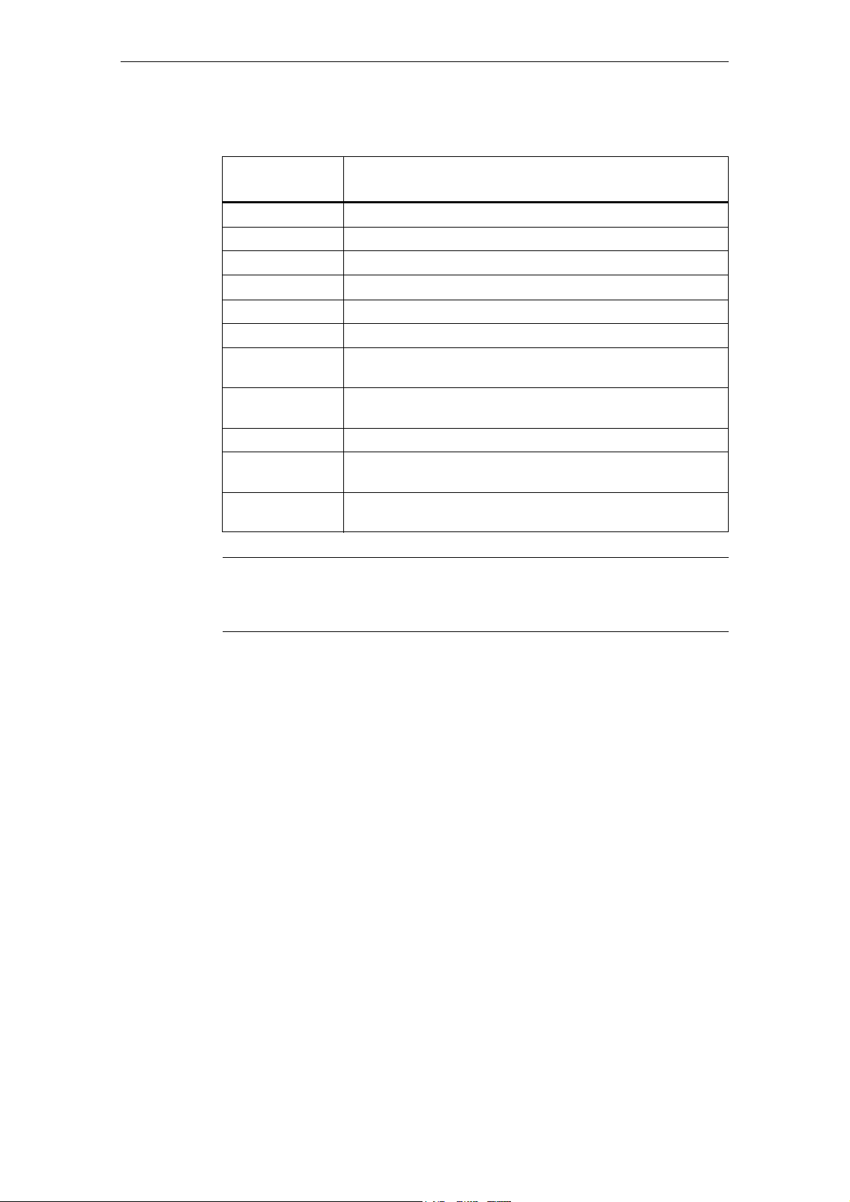
Table 1-1 Data in "Drive object (function module)" field
Parameters
Overview of parameters
Drive object (func-
tion module)
CU Control Unit, (all variants)
CU_S Control Unit SINAMICS S (SINAMICS S120/S150)
TB30 Terminal Board 30
TM31 Terminal Module 31
TM41 Terminal Module 41
VECTOR Vector drive
VECTOR (n/M) Vector drive with function module "Closed-loop speed/torque con-
trol" (r0108.2)
VECTOR (ext.
brake)
VECTOR (parallel) Vector drive with function module "Parallel connection" (r0108.15)
VECTOR (techn.
ctrl)
VECTOR (ext.
mess.)
Vector drive with function module "Extended brake control"
(r0108.14)
Vector drive with function module "Technology controller"
(r0108.16)
Vector drive with function module "Extended reports/monitors"
(r0108.17)
Meaning
Note:
Changeable in
References: /IH1/ SINAMICS S120 Commissioning Manual
in section "Drive Objects"
The "-" sign indicates that the parameter can be changed in any object state and
that the change will be effective immediately.
The letters "C1, C2, T, U" mean that the parameter can be changed only in the
specified drive object state and that the change will not take effect until the object
switches to another state. This can be one or more states.
Siemens AG 2004 All Rights Reserved
SINAMICS G List Manual, Edition 12.2004
1-15

Parameters
Overview of parameters
The following states may be specified:
• C1 Converter commissioning C1: Commissioning 1
• C2 Drive object commissioning C2: Commissioning 2
• U Operation U: Run
• T Ready T: Ready to run
Converter commissioning is in progress (p0009 > 0).
Pulses cannot be enabled.
A modified parameter value does not take effect until converter commissioning mode is exited with p0009 = 0.
Drive commissioning is in progress (p0009 = 0 and p0010 > 0).
Pulses cannot be enabled.
A modified parameter value does not take effect until drive commissioning mode is exited with p0010 = 0.
Pulses are enabled.
Pulses are not enabled and status "C1" or "C2" is not active.
Note:
Parameter p0009 is CU-specific (belongs to control unit).
Parameter p0010 is drive-specific (belongs to each drive object).
The operating status of individual drive objects is displayed in r0002.
Access level (refers only to access via Basic Operator Panel)
Specifies the access level required to be able to display and change the relevant
parameter. The required access level can be set via p0003.
The system uses the following access levels:
1. Standard
2. Extended
3. Expert
4. Service
Note:
1-16
Parameter p0003 is CU-specific (belongs to control unit).
Siemens AG 2004 All Rights Reserved
SINAMICS G List Manual, Edition 12.2004

Data type
Data set
Parameters
Overview of parameters
The possible data types of parameter values are as follows:
• I8 Integer8 8-bit integer
• I16 Integer16 16-bit integer
• I32 Integer32 32-bit integer
• U8 Unsigned8 8 bits without sign
• U16 Unsigned16 16 bits without sign
• U32 Unsigned32 32 bits without sign
• Float FloatingPoint Floating point number
Parameters which are dependent on a data set are identified as follows:
• CDS (Command Data Set)
• DDS (Drive Data Set)
• EDS (Encoder Data Set)
• MDS (Motor Data Set)
• PDS (Power Module Data Set)
Note:
References: /IH1/ SINAMICS S120 Commissioning Manual
Function diagram
The parameter is included in this function diagram. The structure of the parameter
function and its interrelationship with other parameters is shown in the specified
function diagram.
Example:
Function diagram: 3060.3 3060: Function diagram number
Example:
p1070[0] Æ main setpoint [command data set 0]
p1070[1] Æ main setpoint [command data set 1], etc.
in section "Data Sets"
Siemens AG 2004 All Rights Reserved
SINAMICS G List Manual, Edition 12.2004
3: Signal path (optional)
1-17

Parameters
Overview of parameters
P group (refers only to access via BOP (Basic Operator Panel))
Specifies the functional group to which the parameter belongs. The required
parameter group can be set via p0004.
Note:
Parameter p0004 is CU-specific (belongs to control unit).
Unit, unit group and unit choice
The following applies to parameters with a unit:
• Each of these parameters is assigned to a unit group.
• The relevant unit for the parameter is specified in square parenthesis.
• If the parameter unit can be set within the unit group, then the parameters
required to do so are specified under "Unit choice".
Note:
References: /IH1/ SINAMICS S120 Commissioning Manual
Parameter values
Min Minimum value of the parameter [unit]
Max Maximum value of the parameter [unit]
Factory Setting Shipped value (default) [unit]
Description
Explanation of the function of a parameter.
Values
in section "Units"
A different value may be displayed for certain parameters
(e. g. p1800) at the initial commissioning stage.
Reason:
The setting of these parameters is determined by the
operating environment of the Control Unit
(e. g. depending on converter type, macro, power module).
Lists the possible values of a parameter.
Recommendation
Information about recommended settings.
1-18
Siemens AG 2004 All Rights Reserved
SINAMICS G List Manual, Edition 12.2004

Index
Bit field
Parameters
Overview of parameters
The name and meaning of each individual index is specified for indexed parameters.
The following applies to the values (min, max, factory setting) of indexed setting
parameters:
• Min, Max:
The setting range and unit apply to all indices.
• Factory setting:
When all indices have the same factory setting, index 0 is specified with unit
to represent all indices.
When the indices have different factory settings, they are all listed individually
with unit.
For parameters with bit fields, the following information is provided about each bit:
Dependency
• Bit number and signal name
• Meaning with signal states 0 and 1
• Function diagram (optional)
The signal is shown on this function diagram.
Conditions which need to be fulfilled in connection with this parameter. Also
includes special effects which can occur between this parameter and others.
see also: List of other relevant parameters.
Siemens AG 2004 All Rights Reserved
SINAMICS G List Manual, Edition 12.2004
1-19

Parameters
Overview of parameters
Safety Information
Important information which must be heeded to avoid the risk of physical injury or
property damage.
Information which must be observed to avoid problems.
Information which the user or operator may find useful.
Danger! Corresponds to
Danger
Warning! Corresponds to
Caution! Corresponds to
Warning
Caution
Caution: Corresponds to Caution
Notice: Corresponds to Important
Note:
A description of individual safety notices can be found in the appendix to this manual (see Safety Information).
1-20
Siemens AG 2004 All Rights Reserved
SINAMICS G List Manual, Edition 12.2004

1.1.2 Numerical ranges of parameters
Parameters are grouped into the following numerical ranges:
Table 1-2 Numerical Ranges of Parameters
Range Description
From To
0000 0099 Operation and visualization
0100 0199 Commissioning
0200 0299 Power module
0300 0399 Motor
0400 0499 Encoder
0500 0599 Technology and units
0600 0699 Thermal motor protection and motor model, maximum current
0700 0799 Command sources and terminals on control unit, measuring
sockets
0800 0839 CDS, DDS data sets (e.g. switch over, copy)
0840 0879 Sequential control (e.g. source for ON/OFF1)
Parameters
Overview of parameters
0880 0899 Control and status words
0900 0999 PROFIBUS/PROFIdrive
1000 1199 Setpoint channel
1200 1299 Functions (e.g. motor holding brake)
1300 1399 V/f control
1400 1799 Closed-loop control
1800 1899 Gating unit
1900 1999 Power module and motor identification
2000 2099 Communication (PROFIBUS)
2100 2199 Faults and alarms, monitoring functions
2200 2399 Techn. ctrl
2900 2930 Fixed values (e.g. per cent, torque)
3400 3699 Infeed control (Active Line Module)
3900 3999 Management parameters
4000 4199 Terminal boards, terminal modules (e.g. TB30, TM31)
6500 6599 External reports
7000 7499 Parallel connection of power modules
7800 7899 EEPROM read/write parameters
8800 8899 Communication board
9400 9499 Parameter consistency and storage
Siemens AG 2004 All Rights Reserved
SINAMICS G List Manual, Edition 12.2004
1-21

Parameters
Overview of parameters
Table 1-2 Numerical Ranges of Parameters, continued
From To
9500 9899 Safety Integrated
9900 9949 Topology
9950 9999 Diagnostics (internal)
Range Description
1-22
Siemens AG 2004 All Rights Reserved
SINAMICS G List Manual, Edition 12.2004

Parameters
Parameter list
1.2 Parameter list
Product: SINAMICS G, Version: V02.20.28.00, Lab el: ARM_M0475_11, Language: en
r0002 Control module, operating display / CU op_display
CU Can be changed: - Access level: 1
Data type: Integer16 Data set: - Function diagram: P-Group: - Units group: - Unit selection: -
Min Max Factory setting
- - -
Description: Operating display for the control board.
Values: 0: [00] Operation
10: [10] Ready
20: [20] Wait for run-up
31: [31] Commissioning software download active
33: [33] Remove topology error / acknowledge
34: [34] Exit the commissioning mode
35: [35] Carry-out first commissioning
70: [70] Initialization
80: [80] Reset active
99: [99] Internal software error
r0002 Drive operating display / Drv op_display
VECTOR Can be changed: - Access level: 1
Data type: Integer16 Data set: - Function diagram: P-Group: - Units group: - Unit selection: -
Min Max Factory setting
- - -
Description: Operating display for the drive.
The value provides information about the actual operating state and the conditions necessary to reach the next
operating state.
The higher the numerical value, the greater the number of conditions that still have to be fulfilled in order to achieve
the "Run" operating state.
Values: 0: [00] Operation - everything enabled
10: [10] Operation - set "enable setpoint" signal to "1" (p1142)
11: [11] Operation - set "enable speed controller" signal to "1" (p0856)
12: [12] Operation - RFG frozen, set "RFG start" signal to "1" (p1141)
13: [13] Operation - set "enable ramp-function generator" signal to "1" (p1140)
14: [14] Operation - wait for the brake opening time (p1216, vector magn_time p0346)
15: [15] Operation - open brake (p1215)
16: [16] Operation - Withdraw braking with OFF1 using "ON/OFF1" signal to "1"
17: [17] Operation - braking with OFF3 can only be interrupted with OFF2
18: [18] Operation - a fault has occurred and the drive brakes - remove the cause of the fault and acknowledge
the fault
21: [21] Ready - set the "enable operation" signal to "1" (p0852)
22: [22] Ready - de-magnetization running (vector de-magn_time p0347)
23: [23] Ready - set "infeed operation" signal to "1" (p0864)
31: [31] Ready to power-up - set the "ON/OFF1" signal with 0/1 edge (p0840)
41: [41] Power-on inhibit - set the "ON/OFF1" signal with 0/1 edge (p0840)
42: [42] Power-on inhibit - set "OC/OFF2" signal to "1" (p0844, p0845)
43: [43] Power-on inhibit - set "OC/OFF3" signal to "1" (p0848, p0849)
44: [44] Power-on inhibit - connect 24 V to terminal EP (hardware)
45: [45] Power-on inhibit - remove the cause of the fault, acknowledge the fault
46: [46] Power-on inhibit - exit the commissioning mode (p0009, p0010)
Dependency: Refer to: r0046
Siemens AG 2004 All Rights Reserved
SINAMICS G List Manual, Edition 12.2004
1-23

Parameters
Parameter list
Note: RFG: Ramp-function generator
OC: Operating condition
EP: Enable Pulses (pulse enable)
r0002 TB30 operating display / TB30 op_display
TB30 Can be changed: - Access level: 1
Data type: Integer16 Data set: - Function diagram: P-Group: - Units group: - Unit selection: -
Min Max Factory setting
- - -
Description: Operating display for terminal board 30 (TB30).
The higher the numerical value, the greater the number of conditions that still have to be fulfilled in order to achieve
the "Run" operating state.
Values: 0: [00] Module in cyclic operation
40: [40] Module not in cyclic operation
60: [60] Fault
70: [70] Initialization
80: [80] Reset active
r0002 TM31 operating display / TM31 op_display
TM31 Can be changed: - Access level: 1
Data type: Integer16 Data set: - Function diagram: P-Group: - Units group: - Unit selection: -
Min Max Factory setting
- - -
Description: Operating display for terminal board 31 (TB31).
The higher the numerical value, the greater the number of conditions that still have to be fulfilled in order to achieve
the "Run" operating state.
Values: 0: [00] Module in cyclic operation
40: [40] Module not in cyclic operation
50: [50] Alarm
60: [60] Fault
70: [70] Initialization
p0003 BOP access level / BOP access level
CU Can be changed: C1, U, T Access level: 1
Data type: Integer16 Data set: - Function diagram: P-Group: All groups Units group: - Unit selection: -
Min Max Factory setting
1 4 1
Description: Sets the access level for reading (and writing) parameters via BOP20 and AOP.
Values: 1: Standard
Note: In access level 1 (standard) all of the parameters are available that are required for the basic operator control func-
2: Extended
3: Expert
4: Service
tionality (e.g. p1120 = ramp-function generator, ramp-up time).
In access level 2 (extended), parameters are included that are sufficient to use the basic device functions.
In access level 3 (experts), parameters are included that already require expert knowhow (e.g. knowhow about
BICO parameterization).
Parameters belonging to access level 4 (service) can only be modified after entering an appropriate code.
1-24
Siemens AG 2004 All Rights Reserved
SINAMICS G List Manual, Edition 12.2004

Parameters
Parameter list
p0004 BOP parameter menu / BOP par_menu
CU Can be changed: C2, T Access level: 1
Data type: Integer16 Data set: - Function diagram: P-Group: All groups Units group: - Unit selection: -
Min Max Factory setting
0 99 1
Description: Display filter for BOP20 and AOP for selecting parameters using menu prompting.
Values: 0: All parameters
1: Displays, signals
2: Power module
3: Motor
4: Encoder/position encoder
5: Technology, units
7: Digital inputs/outputs, commands, sequential control
8: Analog inputs/outputs, terminal strip
10: Setpoint channel/ramp-fct generator
12: Functions
13: V/f control
14: Control
15: Data sets
18: Gating unit, modulator
19: Motor identification, power module test
20: Communication
21: Faults, alarms, monitoring functions
25: Closed-loop position control
28: Free function blocks
47: Trace and function generator
50: OEM parameter
90: Topology
95: Safety Integrated
98: Command Data Set (CDS)
99: Drive Data Set (DDS)
p0007 Backlighting display delay time / Display t_del
CU Can be changed: U, T Access level: 3
Data type: Unsigned32 Data set: - Function diagram: P-Group: - Units group: - Unit selection: -
Min Max Factory setting
0 2 0
Description: Sets the delay time to switch-out background lighting.
If no keys are actuated, then the background lighting automatically switches itself off after this time has expired.
Note: p0007 = 0: Background lighting is always switched on (factory setting).
p0009 Device commissioning parameter filter / Dev comm par_filt
CU Can be changed: C1, T Access level: 1
Data type: Integer16 Data set: - Function diagram: P-Group: All groups Units group: - Unit selection: -
Min Max Factory setting
0 30 1
Description: Sets the device and basic drive commissioning.
By appropriately setting this parameter, those parameters are filtered that can be written into in the various commissioning steps.
Siemens AG 2004 All Rights Reserved
SINAMICS G List Manual, Edition 12.2004
1-25

Parameters
Parameter list
Values: 0: Ready
1: Device configuration
2: Definition drive type (in preparation)
3: Drive basis configuration
4: Data set basis configuration
29: Device download
30: Parameter reset
Note: The drives can only be powered-up outside the device commissioning (the inverter enabled). In this case, p0009
must be 0 (Ready) and the individual drive objects must have already gone into operation (p0010).
p0009 = 1: Device configuration
At the first commissioning of the devices, after run-up, the device is in the "device configuration" state. To start the
internal automatic first commissioning of the drive unit, p0009 should be set to 0 (Ready) after the ID for the actual
topology (r0098) was transferred into the ID for the target topology (p0099). To do this, it is sufficient to set a single
index value of p0099[x] the same as r0098[x]. Before the device has been completely commissioned, no other
parameter can be changed. After the first commissioning was carried-out, in this state, when required, other basic
device configuration parameters can be adapted (e.g. the basic clock cycle in p0110).
p0009 = 3: Drive basis configuration
In this state, after the device has been commissioned for the first time, basic changes can be made for the individ-
ual drive objects (e.g. sampling rates p0111, p0112, p0115 and the number of data sets p0120, p0130, p0140,
p0170, p0180).
p0009 = 4: Data set basis configuration
In this state, after the device has been commissioned for the first time, for the individual drive objects changes can
be made regarding the assignment of the components (p0121, p0131, p0141, p0151, p0161) to the individual data
sets and the assignment of the power module, motor and encoder to the drive data sets (p0185, and onwards).
p0009 = 29: Device download
If a download is made using the commissioning software, the device is automatically brought into this state. After
the download has been completed, p0009 is automatically set to 0 (ready). It is not possible to manually set p0009
to this value.
p0009 = 30: Parameter reset
In order to bring the complete unit into the "first commissioning" state or to load the parameters saved using p0977,
to start, p0977 must be set to this value. p0976 can then be changed to the required value.
p0010 Drive, commissioning parameter filter / Drv comm. par_filt
VECTOR Can be changed: C2, T Access level: 1
Data type: Integer16 Data set: - Function diagram: P-Group: All groups Units group: - Unit selection: -
Min Max Factory setting
0 95 1
Description: Sets the parameter filter to commission a drive.
Setting this parameter filters-out the parameters that can be written into in the various commissioning steps.
Values: 0: Ready
1: Quick commissioning
2: Power module commissioning
3: Motor commissioning
4: Encoder commissioning
5: Technological application/units
15: Data sets
29: Download
30: Parameter reset
95: Safety Integrated commissioning
Note: The drive can only be powered-up outside the drive commissioning (inverter enable). To realize this, this parameter
must be set to 0.
For p3900 not equal to 0, at the end of the quick commissioning, this parameter is automatically reset to 0.
Procedure for "parameter reset": Set p0010 = 30 and p0970 = 1.
1-26
Siemens AG 2004 All Rights Reserved
SINAMICS G List Manual, Edition 12.2004

Parameters
Parameter list
p0010 TB30 commissioning parameter filter / TB30 comm.par_filt
TB30 Can be changed: C2, T Access level: 1
Data type: Integer16 Data set: - Function diagram: P-Group: All groups Units group: - Unit selection: -
Min Max Factory setting
0 30 0
Description: Sets the parameter filter for commissioning a terminal board 30 (TB30).
Setting this parameter filters-out the parameters that can be written into in the various commissioning steps.
For the BOP, this setting also causes the read access operations to be filtered.
Values: 0: Ready
29: Download
30: Parameter reset
Dependency: Refer to: p0970
Note: Procedure for "parameter reset": Set p0010 = 30 and p0970 = 1.
p0010 TM31 commissioning parameter filter / TM31 comm par_filt
TM31 Can be changed: C2, T Access level: 1
Data type: Integer16 Data set: - Function diagram: P-Group: All groups Units group: - Unit selection: -
Min Max Factory setting
0 30 0
Description: Sets the parameter filter for commissioning a terminal module 31 (TB31).
Setting this parameter filters-out the parameters that can be written into in the various commissioning steps.
For the BOP, this setting also causes the read access operations to be filtered.
Values: 0: Ready
29: Download
30: Parameter reset
Dependency: Refer to: p0970
Note: Only the following values are possible: p0010 = 0, 30
Procedure for "parameter reset": Set p0010 = 30 and p0970 = 1.
p0015 Macro drive unit / Macro drv unit
CU Can be changed: C1 Access level: 1
Data type: Unsigned32 Data set: - Function diagram: P-Group: - Units group: - Unit selection: -
Min Max Factory setting
0 999999 0
Description: Runs the appropriate ACX file on the CompactFlash Card.
The selected ACX file must be located in the following directory:
... /PMACRO/DEVICE/P15/PMxxxxxx.ACX
Example:
p0015 = 6 --> the file PM000006.ACX is run.
Dependency: The ACX file to be run must be created according to the definition for ACX macros and must be saved in the direc-
tory intended on the CompactFlash Card.
Refer to: p0015, p0700, p1000, p1500
Siemens AG 2004 All Rights Reserved
SINAMICS G List Manual, Edition 12.2004
1-27

Parameters
Parameter list
p0015 Macro drive object / Macro DO
VECTOR Can be changed: C2 Access level: 1
Data type: Unsigned32 Data set: - Function diagram: P-Group: Commands Units group: - Unit selection: -
Min Max Factory setting
0 999999 0
Description: Runs the appropriate ACX file on the CompactFlash Card.
The selected ACX file must be located in the following directory:
... /PMACRO/<drive object>/P15/PMxxxxxx.ACX
Example:
p0015 = 6 --> the file PM000006.ACX is run.
Dependency: The ACX file to be run must be created according to the definition for ACX macros and must be saved in the direc-
tory intended on the CompactFlash Card.
Refer to: p0700, p1000, p1500
r0018 Control unit firmware version / CU FW_version
CU Can be changed: - Access level: 1
Data type: Unsigned32 Data set: - Function diagram: P-Group: - Units group: - Unit selection: -
Min Max Factory setting
- - -
Description: Displays the firmware version of the control unit.
Dependency: Refer to: r0128, r0148, r0158, r0197, r0198
Note: Example:
The value 1010100 should be interpreted as V01.01.01.00.
r0020 Speed setpoint, smoothed / n_set smth
VECTOR Can be changed: - Access level: 2
Data type: Floating Point Data set: - Function diagram: 5020
P-Group: Displays, signals Units group: SPEED_ROT Unit selection: -
Min Max Factory setting
- [1/min] - [1/min] - [1/min]
Description: Displays the actual smoothed speed/velocity setpoint at the input of the speed/velocity controller or V/f characteris-
tic (after the interpolator).
Dependency: Refer to: r0060
Note: Smoothing time constant: 100 ms
The signal is not suitable as process quantity and may only be used as display quantity.
The speed setpoint is available smoothed (r0020) and unsmoothed (r0060).
r0021 Actual speed, smoothed / n_act smooth
VECTOR Can be changed: - Access level: 2
Data type: Floating Point Data set: - Function diagram: 1580,
4710, 6010
P-Group: Displays, signals Units group: SPEED_ROT Unit selection: -
Min Max Factory setting
- [1/min] - [1/min] - [1/min]
Description: Displays the smooth actual value of the motor speed/velocity.
Dependency: Refer to: r0063
1-28
Siemens AG 2004 All Rights Reserved
SINAMICS G List Manual, Edition 12.2004

Parameters
Parameter list
Note: Smoothing time constant: 100 ms
The signal is not suitable as process quantity and may only be used as display quantity.
The value displayed in r0021 is the smoothed value of r0063.
r0024 Drive output frequency smoothed / Drv outp_f smooth
VECTOR Can be changed: - Access level: 3
Data type: Floating Point Data set: - Function diagram: 1690,
P-Group: Displays, signals Units group: FREQUENCY Unit selection: -
Min Max Factory setting
- [Hz] - [Hz] - [Hz]
Description: Displays the smoothed converter frequency.
Dependency: Refer to: r0066
Note: Smoothing time constant: 100 ms
The signal is not suitable as process quantity and may only be used as display quantity.
The output frequency is available smoothed (r0024) and unsmoothed (r0066).
5300, 5730
r0025 Drive, output voltage smoothed / Drv U_outp smooth
VECTOR Can be changed: - Access level: 2
Data type: Floating Point Data set: - Function diagram: 1690,
5730
P-Group: Displays, signals Units group: VOLTAGE_AC_EFF Unit selection: -
Min Max Factory setting
- [Veff] - [Veff] - [Veff]
Description: Displays the smoothed output voltage of the power module.
Dependency: Refer to: r0072
Note: Smoothing time constant: 100 ms
The signal is not suitable as process quantity and may only be used as display quantity.
The output voltage is available smoothed (r0025) and unsmoothed (r0072).
r0026 DC link voltage, smoothed / Vdc smooth
VECTOR Can be changed: - Access level: 2
Data type: Floating Point Data set: - Function diagram: 6730,
6731
P-Group: Displays, signals Units group: VOLTAGE_DC Unit selection: -
Min Max Factory setting
- [V] - [V] - [V]
Description: Displays the smoothed actual value of the DC link voltage.
Dependency: Refer to: r0070
Note: A_INF: Smoothing time constant = 300 ms
SERVO, VECTOR: Smoothing time constant = 100 ms
The signal is not suitable as process quantity and may only be used as display quantity.
The DC link voltage is available smoothed (r0026) and unsmoothed (r0070).
Siemens AG 2004 All Rights Reserved
SINAMICS G List Manual, Edition 12.2004
1-29

Parameters
Parameter list
r0027 Absolute actual current, smoothed / I_act abs.val.smth
VECTOR Can be changed: - Access level: 2
Data type: Floating Point Data set: - Function diagram: 5730,
6714, 8950
P-Group: Displays, signals Units group: CURRENT_AC_EFF Unit selection: -
Min Max Factory setting
- [Aeff] - [Aeff] - [Aeff]
Description: Displays the smoothed absolute actual current value.
Dependency: Refer to: r0068
Note: A_INF, VECTOR: Smoothing time constant = 300 ms
SERVO: Smoothing time constant = 100 ms
The signal is not suitable as process quantity and may only be used as display quantity.
The absolute current actual value is available smoothed (r0027) and unsmoothed (r0068).
r0028 Modulation depth, smoothed / Modulat depth smth
VECTOR Can be changed: - Access level: 3
Data type: Floating Point Data set: - Function diagram: 5730,
8940, 8950
P-Group: Displays, signals Units group: PERCENT Unit selection: -
Min Max Factory setting
- [%] - [%] - [%]
Description: Displays the smoothed actual value of the modulation depth.
Dependency: Refer to: r0074
Note: A_INF: Smoothing time constant = 300 ms
SERVO, VECTOR: Smoothing time constant = 100 ms
The signal is not suitable as process quantity and may only be used as display quantity.
The modulation depth is available smoothed (r0028) and unsmoothed (r0074).
r0029 Drive, smoothed field-generating current actual value / Drv Id_act smooth
VECTOR Can be changed: - Access level: 3
Data type: Floating Point Data set: - Function diagram: 5730
P-Group: Displays, signals Units group: CURRENT_AC_EFF Unit selection: -
Min Max Factory setting
- [Aeff] - [Aeff] - [Aeff]
Description: Displays the smoothed field-generating actual current.
Dependency: Refer to: r0076
Note: SERVO: Smoothing time constant = 100 ms
VECTOR: Smoothing time constant = 300 ms
The signal is not suitable as process quantity and may only be used as display quantity.
The field-generating current actual value is available smoothed (r0029) and unsmoothed (r0076).
r0030 Current actual value, torque-generating, smoothed / Iq_act smooth
VECTOR Can be changed: - Access level: 3
Data type: Floating Point Data set: - Function diagram: 5730
P-Group: Displays, signals Units group: CURRENT_AC_EFF Unit selection: -
Min Max Factory setting
- [Aeff] - [Aeff] - [Aeff]
Description: Displays the smoothed torque-generating actual current.
Dependency: Refer to: r0078
1-30
Siemens AG 2004 All Rights Reserved
SINAMICS G List Manual, Edition 12.2004
 Loading...